

Heat Transfer and Thermal Efficiency in Oxy-Fuel Retrofit of 0.5 MW Fire Tube Gas Boiler


School of Mechanical Engineering, Kookmin University, Seoul 02707, Republic of Korea
Processes 2024, 12(5), 959; https://doi.org/10.3390/pr12050959
Submission received: 30 March 2024
/
Revised: 6 May 2024
/
Accepted: 7 May 2024
/
Published: 9 May 2024
(This article belongs to the Special Issue Thermal and Fluid Flow Processes in Sustainable and Conventional Energy)
Abstract
:Industrial boilers cause significant energy wastage that could be mitigated with oxy-fuel combustion versus traditional air combustion. Despite several feasibility studies on oxy-fuel burners, they are widely avoided in industry due to major infrastructural challenges. This study measured the performance and heat transfer characteristics of each component in a 0.5 MW fire tube gas boiler after retrofitting it with an oxy-fuel burner. Comparisons were drawn across three combustion modes—air combustion, oxy-fuel combustion, and oxy-fuel flue gas recirculation (FGR). The Dittus–Boelter equation was employed to predict heat transfer in the fire tube for all combustion modes at full load (100%). Heat transfer in the latent heat section of the economizer was measured and compared with predictions using the Zukauskas equation. With this retrofit, oxy-fuel combustion improved the thermal efficiency by about 3–4%. In oxy-fuel combustion, the flow rate of exhaust gas decreased. When integrated into an existing fire tube boiler, the fire tube’s heat transfer contribution diminished greatly, suggesting the economic viability of a redesigned, reduced fire tube section. Additionally, a new design could address the notable increase in gas radiation from the fire tube in oxy-fuel and FGR, as well as aid in the efficient recovery of condensation heat from exhaust gases.
1. Introduction
Oxy-fuel combustion is a process in which a fuel is burned using oxygen instead of air. Oxy-fuel combustion produces flue gases with a higher concentration of carbon dioxide (CO2) compared to traditional combustion with air. This benefits carbon capture and storage (CCS) applications, making it simpler to capture and sequester the concentrated CO2 stream, thereby reducing greenhouse gas emissions [1].
Oxy-fuel combustion can lead to improved heat transfer rates due to its higher flame temperatures and the reduced inert gas content in the combustion products [2]. This can lead to more efficient heat transfer processes in various industrial applications, such as glass melting, metal smelting, and power generation [2,3]. Oxy-fuel combustion can emit fewer pollutants such as nitrogen oxides (NOx) and sulfur oxides (SOx) compared to air–fuel combustion, owing to the absence of nitrogen in the combustion process and finer control over the combustion conditions [4].
Despite its advantages, oxy-fuel combustion has yet to become widespread for several reasons. Implementing oxy-fuel combustion systems can be expensive due to the need for specialized equipment to separate and supply oxygen to the combustion process [5]. For example, an analysis showed that an energy penalty of 3–4% would occur when separating oxygen from air using a cryogenic air separation unit (ASU) [6]. Moreover, the cost associated with capturing and sequestering the concentrated CO2 stream generated by oxy-fuel combustion can be substantial [7].
The widespread adoption of oxy-fuel combustion would require significant infrastructure changes, including modifications to existing combustion systems. These infrastructure challenges act as barriers to adoption, particularly in industries with well-established traditional air–fuel combustion systems. Retrofitting existing combustion systems with oxy-fuel technology can help reduce upfront capital costs [8]. However, retrofitting an existing combustion system to enable oxy-fuel combustion can present several challenges and potential problems. Compatibility issues may arise with existing equipment, materials, and control systems, necessitating modifications or replacements. Retrofitting may also demand modifications to heat transfer surfaces, fluid flow patterns, and combustion chamber designs to optimize the heat transfer efficiency [9].
Research on replacing current combustion systems with oxy-fuel combustion has been ongoing for over 20 years [10]. The change in burner design for oxy-fuel combustion can result in alterations to flame characteristics, including the flame shape, temperature distribution, and stability. Oxy-fuel combustion typically produces more compact flames compared to air–fuel combustion due to the absence of nitrogen dilution [2]. Oxy-fuel combustion also produces higher flame temperatures compared to air–fuel combustion, thereby increasing heat transfer rates to ensure compatibility with existing systems [11].
Thus far, studies and demonstrations showcasing the performance of oxy-fuel combustion in pilot plants have primarily focused on boilers for coal-fired power plants [12]. However, both industrial boilers and power generation boilers contribute significantly to global energy consumption [13]. Power generation boilers are commonly water tube boilers designed to operate at high pressures and temperatures to maximize thermal efficiency [14]. Industrial boilers, on the other hand, come in a variety of designs, including fire tube, water tube, and package boilers, depending on the specific application and requirements of the industrial process [15].
In a study on applying oxy-fuel combustion to an industrial boiler, Ahn et al. [16] compared air combustion and oxy-fuel combustion in the combustion chamber of a furnace-type boiler and showed that retrofitting was possible by replacing the burner. Introducing flue gas recirculation (FGR) into an oxy-fuel boiler offers several benefits, including reductions in emissions, improved combustion stability, and enhanced carbon capture performance [17]. Ben-Mansour et al. [18] compared air combustion and oxy-fuel FGR combustion in a water tube boiler. Mansir et al. [19] and Ahn et al. [20] compared the two combustion methods in a fire tube boiler. FGR can further decrease the flame temperature, helping to mitigate issues such as high-temperature corrosion and thermal NOx formation [21].
The aforementioned studies [16,17,18,19,20,21] focused on the combustion chamber’s flame and heat transfer characteristics. However, to successfully retrofit oxy-fuel combustion into existing industrial boilers, it is essential to consider heat transfer in components beyond the combustion chamber. Published papers on heat transfer research in oxy-fuel combustion are relatively scarce compared to those on flame or burner research [2]. Additionally, most heat transfer studies of oxy-fuel combustion focus on radiative heat transfer in the combustion chamber [22]. In oxy-fuel combustion, gas radiation becomes more important than it is in air combustion. Among the studies that outline this important facet of oxy-fuel combustion, Johansson et al. [23] presented gas radiation properties; Bhuiyan et al. [24] examined both radiation and convection heat transfer but only presented data around the burner. In contrast, the presented study examined heat transfer in the fire tube and economizer of a fire tube boiler, observing its performance during the retrofitting of an oxy-fuel burner.
In this study, a versatile burner capable of operating in air, oxy-fuel, and FGR combustion modes was designed and manufactured, as depicted in Figure 1a. The primary aim was to retrofit an oxy-fuel burner onto a fire tube boiler fueled by natural gas [19]. The burner was coaxially configured to efficiently heat the combustion chamber during oxy-fuel combustion, minimizing the flame volume. For air and FGR combustion, oxidizer supply occurred through a swirler located in the outer annular space of the double layer, ensuring flame stability. The burner illustrated in Figure 1a was integrated into the fire tube industrial boiler shown in Figure 1b, constructing a system capable of producing high concentrations of carbon dioxide.
To account for the heat transfer characteristics in the heat recovery area, an economizer, recovering sensible and latent heat, was serially installed at the boiler body outlet. Prior work on this system presented flame images and the heat flux distribution on the combustion chamber wall [19]. In this paper, a comparative analysis of thermal efficiency and heat transfer across the three combustion modes, air, oxy-fuel, and FGR, is undertaken, focusing on the retrofitting of the oxy-fuel burner. Specifically, the heat transfer coefficients within the fire tubes and economizers, which are not previously documented in the literature, are presented and juxtaposed with empirical equations employed in the design. Through this analysis, we aim to elucidate the alterations in heat transfer within distinct boiler components following the retrofitting with oxy-fuel combustion, thereby proposing potential design enhancements.
2. Materials and Methods
The experimental setup, illustrated in Figure 2, was devised to achieve a high concentration of carbon dioxide by implementing oxy-fuel combustion in an industrial boiler, as depicted in Figure 1 [19]. This 0.5 MW fire tube boiler was equipped with both FGR capabilities and a condensing economizer. Utilizing liquefied natural gas (LNG) as the fuel supplied through a filter to the burner (Figure 1a), the fuel flow rate stood at 40 Nm3/h under 100% load conditions. Fuel was injected from the burner through 12 nozzles, each with a diameter of 6 mm, as illustrated in Figure 1a. During operation at 100% load, the injection velocity reached 32.7 m/s, resulting in a Reynolds number of 12,000.
In oxy-fuel combustion, precise control over the oxygen flow rate was achieved through an electronic valve integrated with a mass flow controller, ensuring a consistent flow of 78 Nm3/h even under 100% load conditions. Conversely, in air combustion, adjustments to the air flow rate were managed by monitoring the exhaust gas oxygen concentration and modulating the blower inverter rotation speed. A flow rate of approximately 380 Nm3/h was maintained to sustain an exhaust gas oxygen concentration of 3.5%. For FGR (flue gas recirculation) combustion, the flow rate of recirculated gas was regulated by an inverter to match the desired oxygen concentration in the oxidizer, set at 35% and 40%, respectively. The recirculation rates were approximately 3.4 and 2.7 for each respective condition [17].
The fire tube boiler features a two-pass structure, where exhaust gas from the combustion chamber circulates through the fire tube towards the burner, enhancing the heat transfer efficiency. The fire tubes have an inner diameter of 0.0242 m and a length of 0.75 m, totaling 80 tubes. The combustion chamber measures 0.82 m in diameter and 1.4 m in length. Additionally, a 150 mm diameter quartz observation window installed in the combustion chamber facilitates the observation of front and side flames. A SONY TRV-30 camcorder was strategically positioned to capture still photos and videos.
The internal combustion chamber temperature was monitored to assess the impact of high-temperature flames from oxy-fuel combustion and the internal temperature distribution due to recirculation. R-type thermocouples from OMEGA, capable of measuring temperatures up to 1450 °C, were strategically placed within the combustion chamber. The temperature distribution inside the chamber was obtained by moving a thermocouple from the central axis towards the chamber wall, as depicted in Figure 2b.
To ascertain the combustion chamber heat transfer, combustion gas temperatures were measured at the chamber inlet and outlet using K-type thermocouples from OMEGA, with an error margin of ±2.1 °C at 300 °C. Uncertainty in the heat transfer rate, calculated with a 95% confidence interval, factored in the flow meter and temperature sensor accuracies [25]. For instance, at 100% load under air combustion conditions, when the fire tube heat transfer rate was 92 kW, the uncertainty was determined to be 1.3 kW.
Furthermore, two economizers connected in series at the boiler body outlet were designed for recovering sensible heat upstream and latent heat downstream. The performance evaluation and boiler efficiency determination involved measuring the combustion gas and feed water temperatures at the inlet and outlet of each economizer. T-type thermocouples from OMEGA, with an accuracy of ±0.8 °C at 100 °C, measured the combustion gas temperatures, while platinum resistance thermometers (Glison MA-247, Gilson, UK) with an accuracy of ±0.2 °C measured the feed water temperatures. Data from all sensors were recorded using a separate hybrid recorder (Yokogawa DR-230, Tokyo, Japan).
Following a 20 min safety purge, the boiler operated until it reached a steady state, which typically required about 30 min. Data collection commenced during steady-state operation, recording and averaging readings over 5 min intervals. The measurements included those of condensation heat transfer, obtained by collecting the water condensate in the economizer. The quantity of condensate collected, ranging from 0.5 to 3 kg for 5 min depending on the combustion mode and load, was measured using a precision scale (OHAUS5202) with an accuracy of 0.01 g.
3. Results and Discussion
3.1. Flame Image and Thermal Efficiency by Combustion Mode
Figure 3 provides a comparative overview of the flame images and temperature distributions within the combustion chamber when utilizing the convertible burner from Figure 1a, as detailed in a previous study [17], across three combustion modes: air, oxy-fuel, and oxy-fuel FGR. In air combustion (Figure 3a), a distinct flame forms near the burner, facilitated by air supplied through a swirler (Figure 1a). Notably, the burner tile becomes red, with a discernible high-temperature area occurring upstream (x/R < 1) within the combustion chamber.
During oxy-fuel combustion (Figure 3b), oxygen injection along the central axis extends the flame along the same axis (r/R = 0), resulting in high-temperature areas along this path. Conversely, in oxy-fuel FGR combustion (Figure 3c) at 100% load, the flame shape and temperature distribution resemble those of air combustion. However, at 50% load, the temperature distribution mirrors that of air combustion, though the burner tile does not exhibit glowing, which contrasts with the air combustion imagery.
By measuring the inlet and outlet temperatures of each boiler component, the heat absorbed by each module was calculated, as illustrated in Figure 4. In air combustion (blue bar in Figure 4a), over 60% of the heat is absorbed within the combustion chamber, with approximately 20% absorbed by both the fire tube and economizer.
In oxy-fuel combustion (green bar in Figure 4a), the bulk of heat within the boiler body is absorbed in the combustion chamber, with a minimal contribution from the fire tube. The enhanced flame temperature during oxy-fuel combustion intensifies radiative heat transfer within the chamber, while reduced flow rates in the fire tube diminish convective heat transfer. Consequently, retrofitting oxy-fuel combustion into existing boilers necessitates new boiler development, given the diminished contribution of the fire tubes to heat transfer.
In oxy-fuel FGR combustion (red bars in Figure 4a), the heat distribution closely resembles that from air combustion, with minor fluctuations across the recirculation rates. While combustion chamber heat absorption decreases by approximately 10%, economizer absorption increases by the same margin. This suggests that retrofitting by burner replacement alone is feasible for existing boilers.
At 50% load (Figure 4b), the proportion of heat absorbed in the combustion chamber increases, while that in the fire tube and economizer decreases, a trend consistent across all combustion modes. However, the rate of absorption reduction in fire tubes versus economizers varies with the combustion mode. Particularly in FGR combustion, the fire tube’s heat absorption diminishes significantly compared to that of the economizer under 50% load conditions. Notably, at 50% load in oxy-fuel and FGR combustion, the economizer heat absorption is approximately double that of when it is subject to air combustion.
Thermal efficiency calculations, based on the high heating value, utilize both the heat balance (Equation (1)) and heat loss methods (Equation (2)) [26,27] and are compared in Figure 5.
With this boiler’s latent heat recovery capacity, its thermal efficiency exceeds 90% across all combustion modes. Oxy-fuel combustion exhibits a 3–4% improvement over air combustion, owing to reduced exhaust gas flow rates [28]. The oxy-fuel FGR efficiency falls between those of air and oxy-fuel oxygen combustion, with circulation rate variations showing a minimal impact.
Overall, there is consistency between the two efficiency calculation methods, except in FGR combustion, where small discrepancies arise. Notably, at 50% load, the boiler efficiency remains largely stable across the combustion modes, with slight deviations observed in FGR combustion, emphasizing the influence of the efficiency calculation method.
3.2. Heat Transfer in Combustion Chamber
A comparison of the combustion chamber outlet temperatures for each combustion mode is illustrated in Figure 6a. As seen in Figure 4, oxy-fuel combustion results in significantly greater heat absorption within the combustion chamber compared to air combustion. However, despite the reduced flow rate, the combustion chamber outlet temperature does not markedly differ from that of air combustion. Even under 50% load, the combustion chamber outlet temperature was observed to be lower than that of air combustion. Notably, the combustion chamber outlet temperature for FGR combustion remained similar to that for air combustion.
The enthalpy of combustion gases can be calculated from the furnace outlet temperature, enabling the determination of heat absorption in the combustion chamber based on changes in enthalpy. Since radiation heat transfer predominates in the combustion chamber, modeling the flame and combustion chamber as surface radiation allows the prediction of flame fullness using Equation (3) [29].
The flame fullness for each combustion method, computed using Equation (3), is compared in Figure 6b. In Equation (3), the flame fullness correlates with the amount of heat absorbed in the combustion chamber. Remarkably, Figure 5 illustrates no significant disparity in heat absorption within the combustion chamber across the different combustion modes, leading to a diminished contrast in flame fullness. Irrespective of the combustion mode, the flame fullness remains approximately 0.4 at 100% load and 0.3 at 50% load, implying that the existing combustion chamber volume can be maintained when transitioning between boiler combustion modes.
3.3. Heat Transfer in Fire Tube
The combustion gases exiting the combustion chamber traverse the fire tube, generating steam. In air combustion, convection predominates in the fire tube, with the design primarily focusing on convective heat transfer [30]. However, in oxy-fuel combustion, radiation’s significance becomes pronounced [17], necessitating its consideration. Radiative heat transfer can be predicted using Equation (4).
The total heat absorbed by the fire tube can be calculated by assessing enthalpy changes at the inlet and outlet, enabling separate computations of radiation and convective heat transfer. The heat transfer coefficients derived from the heat transfer rates facilitate the delineation of the radiation and convection contributions, as depicted in Figure 7.
Observing the proportion of radiation heat transfer, denoted in magenta in Figure 7, reveals its magnitude: approximately 5% for air combustion, escalating to around 40% for oxy-fuel combustion, and approximately 10% for FGR combustion, underscoring the imperative of considering gas radiation in fire tube designs.
In oxy-fuel combustion, at 100% load (Figure 7a), the fire tube’s heat transfer coefficient decreases by about half compared to that in air combustion. Conversely, in the case of FGR, the heat transfer coefficient surpasses that of air combustion. Under 50% load (Figure 7b), differences in the heat transfer coefficient based on the combustion mode diminish as the Reynolds number within the fire tube declines.
During the thermal design of an air combustion boiler, the fire tube’s design relies on convective heat transfer [30]. The Dittus–Boelter equation [31], such as Equation (5), facilitates the prediction of the convective heat transfer coefficient.
Figure 8a illustrates the Nusselt number of the fire tube predicted by Equation (5). As the Dittus–Boelter equation solely accounts for convective heat transfer, the heat transfer coefficient markedly decreases in oxy-fuel combustion due to the lower combustion gas flow rates compared to those in other methods. The normalized values derived from the heat transfer coefficient in Figure 7 are depicted in Figure 8b. At 100% load, the values are nearly identical, hovering around 1. Under 50% load, the heat transfer coefficient for air combustion or FGR is approximately 30% lower than that predicted by the Dittus–Boelter equation. Conversely, in oxy-fuel combustion, the value exceeds the equation’s prediction by over 50%.
3.4. Heat Transfer in Economizer
The combustion gases passing through the fire tube are directed to the economizer for heat recovery. In this system, two economizers were installed, one upstream and one downstream, to recover sensible and latent heat, respectively, from the combustion exhaust gas. Figure 9 illustrates the inlet and outlet temperatures of both the gas side and the water supply side of the economizer at 100% load. On the horizontal axis, Eco 1 refers to the upstream economizer for sensible heat recovery, while Eco 2 denotes the downstream economizer for latent heat recovery.
In Eco 1, responsible for sensible heat recovery, Figure 9a demonstrates a significant drop in the gas-side temperature, whereas Figure 9b shows a minimal rise in the water-side temperature. Conversely, Eco 2, tasked with recovering latent heat, exhibits an opposing trend. Notably, in Eco 2, FGR combustion (red) exhibits a minimal temperature drop on the gas side and a substantial increase on the water side compared to air combustion (blue). This indicates the effective recovery of latent heat as the moisture content increases in the exhaust gas. Even in oxy-fuel combustion scenarios, Eco 2 displays a notable rise in the water-side temperature, indicating effective latent heat recovery.
Figure 4 showcases a slightly higher enthalpy change in the economizer for oxy-fuel combustion compared to other combustion methods. However, the inlet water-side temperature of Eco 1, which represents the final feed water temperature, is lower for oxy-fuel combustion than for FGR. This suggests an incomplete transfer of heat from the gas side to the water side, as depicted in Figure 10.
For upstream economizer 1 (Figure 10a), the heat exchange efficiency is relatively low during air combustion. This stems from the oxy-fuel combustion exhaust gas containing a higher water vapor content than that of air combustion. Consequently, a significant portion of heat exchange occurs in the upstream economizer, where the gas-side heat transfer coefficient is lower than that on the water supply side.
Conversely, in downstream economizer 2 (Figure 10b), condensation drives an elevation in the gas-side heat transfer coefficient, culminating in a heat exchange efficiency close to 1. This increase in the heat transfer coefficient is notably more pronounced during condensation compared to the single phase, as depicted in Figure 11.
The Zhukauskas correlation (Equation (6)), primarily developed for bare tube banks [32], is commonly used in economizer designs [33] that include finned tubes [34].
However, an overall surface efficiency encompassing fin efficiency must be considered when leveraging the equation for fins [35]. Figure 11 demonstrates the ratio of the overall heat transfer coefficient derived from this method to the experimentally obtained heat transfer coefficient based on water-side enthalpy change.
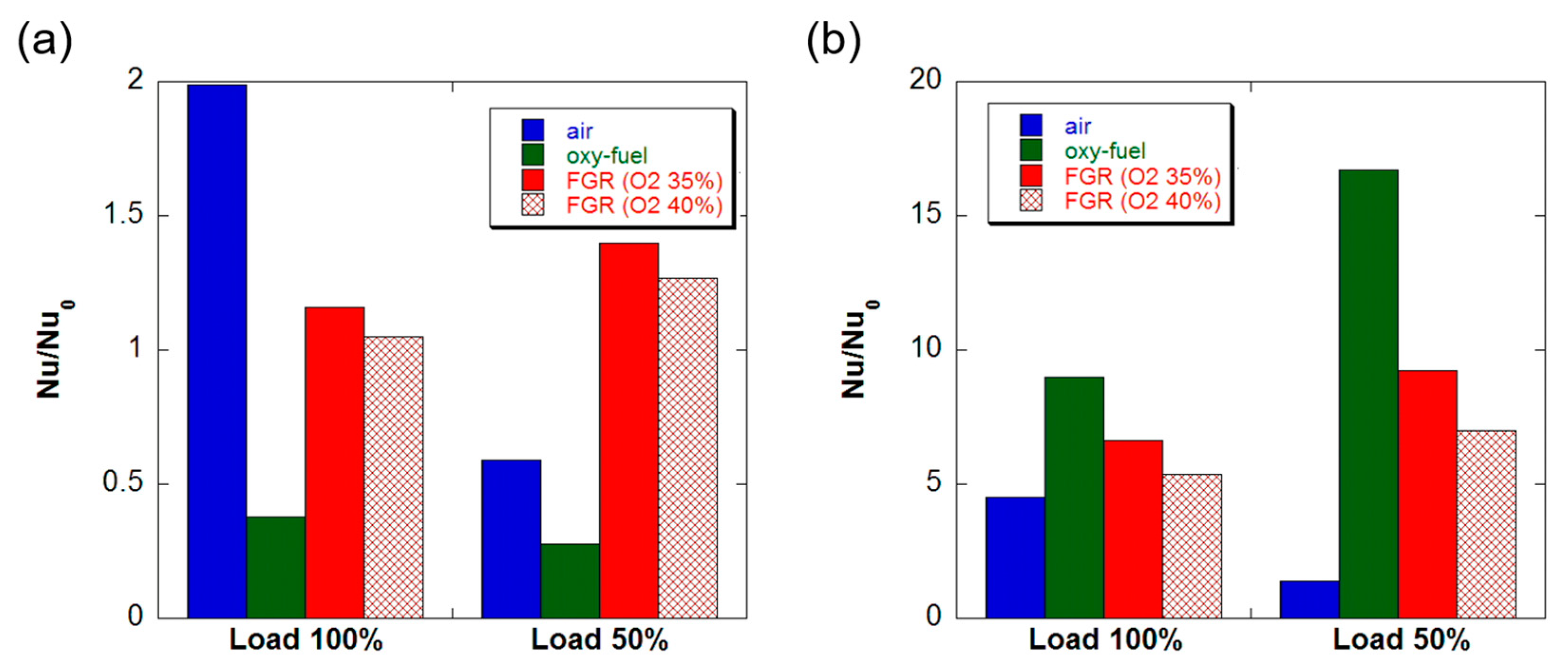
In the case of the upstream economizer (Figure 11a), while FGR combustion is relatively accurately predicted by the Zhukauskas correlation, there are some discrepancies for air and oxy-fuel combustion. Air combustion yields a predicted value that is nearly double the actual value, while oxy-fuel combustion shows a value that is less than 50% of the prediction. In oxy-fuel combustion, this discrepancy may be attributed to the low heat transfer coefficient caused by the minimal flow rate of oxy-fuel, resulting in an overestimation of fin efficiency.
In contrast, for the downstream economizer (Figure 11b), the actual heat transfer coefficient is 4 to 8 times higher than that predicted by the Zhukauskas correlation under 100% load conditions. This significant rise is ascribed to the enhanced heat transfer that takes place during condensation. Notably, combustion methods featuring a higher water vapor content in the exhaust gas, such as oxy-fuel combustion or FGR, exhibit a marked increase in the heat transfer coefficient owing to condensation. Furthermore, at 50% load, the disparity in heat transfer coefficient ratios among the combustion methods widens compared to conditions at 100% load.
4. Conclusions
This investigation involved assessing the performance and heat transfer characteristics of individual components of an oxy-fuel burner retrofitted onto a 0.5 MW fire tube gas boiler. The primary findings are outlined as follows:
- When substituting the burner in a natural-gas-fueled fire tube industrial boiler with an oxy-fuel burner, a comparable level of heat absorption occurs within the combustion chamber, enabling retrofitting. With this modification, oxy-fuel with flue gas recirculation (FGR) achieved a thermal efficiency akin to that with air combustion, and oxy-fuel combustion exhibited a 3–4% enhancement compared to air combustion.
- Oxy-fuel combustion diminishes the exhaust gas flow rate, thereby reducing the fire tube’s contribution to heat transfer when applied to an existing fire tube boiler. Consequently, it was discerned that it would be cost-effective to devise a novel design featuring a smaller fire tube. While gas radiation in the fire tube accounts for less than 5% of the heat transfer in air combustion, its significance escalates in oxy-fuel and FGR combustion, necessitating consideration during design.
- Oxy-fuel combustion and FGR combustion augment the proportion of water vapor in the combustion exhaust gas, facilitating more efficient recovery of condensation heat as compared to air combustion. Furthermore, the efficacy of the sensible heat economizer in oxy-fuel combustion surpassed that in air combustion.
- The Dittus–Boelter equation, employed in fire tube design, accurately projected the heat transfer across all combustion methods under 100% load conditions. However, the predictions deviated slightly under 50% load conditions. Concerning fin–tube heat exchanger economizers, the Zukauskas equation aptly anticipated heat transfer solely for FGR combustion in the sensible heat section. In the latent heat section, a measured heat transfer coefficient 4 to 8 times higher than the value predicted by the Zukauskas equation was recorded.
5. Future Research
The conclusions of this study suggest two potential avenues for future research. Firstly, there is a prospect for the development of a new boiler design that does not require retrofitting existing ones. This could entail minimizing the fire tube portion to conserve materials, while enhancing heat transfer through the utilization of materials optimized for radiant heat transfer in both the combustion chamber and fire tube. Exploring the design and validation of such a specialized oxy-fuel boiler could be proposed as a future research direction.
Secondly, while this study demonstrated a significant increase in the condensation heat transfer coefficient (4 to 8 times higher compared to sensible heat), there is scope for further investigation into the condensation heat transfer phenomenon of oxy-fuel combustion exhaust gas. Developing a systematic understanding and a predictive design equation could significantly contribute to the advancement of highly efficient oxy-fuel boilers.
Funding
This research received no external funding.
Data Availability Statement
The data presented in this study are available on request from the corresponding author.
Conflicts of Interest
The authors declare no conflict of interest.
Nomenclature
| AF | surface area of flame [m2] |
| AFT | surface area of flame tube [m2] |
| AS | boiler external area [m2] |
| AW | combustion chamber wall area [m2] |
| cpg | specific heat of combustion gas [J/kgK] |
| D | tube diameter [m] |
| FGR | flue gas recirculation |
| h | heat transfer coefficient [W/m2K] |
| h0 | heat transfer coefficient outside boiler [W/m2K] |
| hs | specific enthalpy of steam [J/kg] |
| hw | specific enthalpy of feed water [J/kg] |
| HHV | high heating value of fuel [J/kg] |
| k | thermal conductivity [W/mK] |
| mass flow rate of fuel [kg/s] | |
| mass flow rate of fuel [kg/s] | |
| mass flow rate of feed water [kg/s] | |
| Nu | Nusselt number (=hD/k) |
| Pr | Prandtl number (=ν/α) |
| qf | heat rate absorbed per unit volume in combustion chamber [W/m3] |
| r | radial coordinate at combustion chamber [m] |
| R | radius of combustion chamber [m] |
| Re | Reynolds number (=VD/ν) |
| TFT | flame tube surface temperature [K] |
| Tg | combustion gas temperature [K] |
| Ts | boiler surface temperature [K] |
| V | flow velocity [m/s] |
| x | streamwise coordinate from burner [m] |
| α | thermal diffusivity [m2/s] |
| αg | absorptivity of combustion gas |
| εg | emissivity of combustion gas |
| η | thermal efficiency of boiler |
| ν | kinematic viscosity [m2/s] |
| σ | Stefan–Boltzmann constant [W/m2K4] |
References
- Yadav, S.; Mondal, S.S. A review on the progress and prospects of oxy-fuel carbon capture and sequestration (CCS) technology. Fuel 2022, 308, 122057. [Google Scholar] [CrossRef]
- Nemitallah, M.A.; Habib, M.A.; Badr, H.M.; Said, S.A.; Jamal, A.; Ben-Mansour, R.; Mezghani, K. Oxy-fuel combustion technology: Current status, applications, and trends. Int. J. Energy Res. 2017, 41, 1670–1708. [Google Scholar] [CrossRef]
- Faria, D.G.; Carvalho, M.M.; Neto, M.R.; de Paula, E.C.; Cardoso, M.; Vakkilainen, E.K. Integrating oxy-fuel combustion and power-to-gas in the cement industry: A process modeling and simulation study. Int. J. Greenh. Gas Control 2022, 114, 103602. [Google Scholar] [CrossRef]
- Normann, F.; Andersson, K.; Leckner, B.; Johnsson, F. Emission control of nitrogen oxides in the oxy-fuel process. Prog. Energy Combust. Sci. 2009, 35, 385–397. [Google Scholar] [CrossRef]
- Dubey, A.; Arora, A. Advancements in carbon capture technologies: A review. J. Clean. Prod. 2022, 373, 133932. [Google Scholar] [CrossRef]
- He, X.; Liu, Y.; Rehman, A.; Wang, L. A novel air separation unit with energy storage and generation and its energy efficiency and economy analysis. Appl. Energy 2021, 281, 115976. [Google Scholar] [CrossRef]
- Kindra, V.; Rogalev, A.; Lisin, E.; Osipov, S.; Zlyvko, O. Techno-economic analysis of the oxy-fuel combustion power cycles with near-zero emissions. Energies 2021, 14, 5358. [Google Scholar] [CrossRef]
- Fei, Y.; Black, S.; Szuhánszki, J.; Ma, L.; Ingham, D.B.; Stanger, P.J.; Pourkashanian, M. Evaluation of the potential of retrofitting a coal power plant to oxy-firing using CFD and process co-simulation. Fuel Process. Technol. 2015, 131, 45–58. [Google Scholar] [CrossRef]
- Gerbelová, H.; Van Der Spek, M.; Schakel, W. Feasibility assessment of CO2 capture retrofitted to an existing cement plant: Post-combustion vs. oxy-fuel combustion technology. Energy Procedia 2017, 114, 6141–6149. [Google Scholar] [CrossRef]
- Zheng, C.; Liu, Z.; Xiang, J.; Zhang, L.; Zhang, S.; Luo, C.; Zhao, Y. Fundamental and technical challenges for a compatible design scheme of oxyfuel combustion technology. Engineering 2015, 1, 139–149. [Google Scholar] [CrossRef]
- Guo, J.; Liu, Z.; Hu, F.; Li, P.; Luo, W.; Huang, X. A compatible configuration strategy for burner streams in a 200 MWe tangentially fired oxy-fuel combustion boiler. Appl. Energy 2018, 220, 59–69. [Google Scholar] [CrossRef]
- Scheffknecht, G.; Al-Makhadmeh, L.; Schnell, U.; Maier, J. Oxy-fuel coal combustion—A review of the current state-of-the-art. Int. J. Greenh. Gas Control 2011, 5, S16–S35. [Google Scholar] [CrossRef]
- Barma, M.C.; Saidur, R.; Rahman, S.M.A.; Allouhi, A.; Akash, B.A.; Sait, S.M. A review on boilers energy use, energy savings, and emissions reductions. Renew. Sustain. Energy Rev. 2017, 79, 970–983. [Google Scholar] [CrossRef]
- Pronobis, M. Environmentally Oriented Modernization of Power Boilers; Elsevier: Amsterdam, The Netherlands, 2020; pp. 129–135. ISBN 9780128199213. [Google Scholar]
- Echi, S.; Bouabidi, A.; Driss, Z.; Abid, M.S. CFD simulation and optimization of industrial boiler. Energy 2019, 169, 105–114. [Google Scholar] [CrossRef]
- Ahn, J.; Kim, H.J.; Choi, K.S. Oxy-fuel combustion boiler for CO2 capturing: 50 kW-class model test and numerical simulation. J. Mech. Sci. Technol. 2010, 24, 2135–2141. [Google Scholar] [CrossRef]
- Haryanto, A.; Hong, K.S. Modeling and simulation of an oxy-fuel combustion boiler system with flue gas recirculation. Comput. Chem. Eng. 2011, 35, 25–40. [Google Scholar] [CrossRef]
- Ben-Mansour, R.; Habib, M.A.; Nemitallah, M.A.; Rajhi, M.; Suara, K.A. Characteristics of oxyfuel and air–fuel combustion in an industrial water tube boiler. Heat Transf. Eng. 2014, 35, 1394–1404. [Google Scholar] [CrossRef]
- Ahn, J.; Kim, H.J. Combustion characteristics of 0.5 MW class oxy-fuel FGR (flue gas recirculation) boiler for CO2 capture. Energies 2021, 14, 4333. [Google Scholar] [CrossRef]
- Mansir, I.B.; Ben-Mansour, R.; Habib, M.A. Numerical modeling of heat transfer characteristics in a two-pass oxygen transport reactor for fire tube boilers under oxy-fuel combustion. Appl. Therm. Eng. 2021, 195, 117248. [Google Scholar] [CrossRef]
- Ahn, J.; Kim, H.J.; Choi, K.S. Combustion characteristics of oxy-fuel burners for CO2 capturing boilers. J. Therm. Sci. Technol. 2009, 4, 408–413. [Google Scholar] [CrossRef]
- Guo, J.; Hu, F.; Jiang, X.; Huang, X.; Li, P.; Liu, Z.; Zheng, C. Experimental and numerical investigations on heat transfer characteristics of a 35MW oxy-fuel combustion boiler. Energy Procedia 2017, 114, 481–489. [Google Scholar] [CrossRef]
- Johansson, R.; Andersson, K.; Leckner, B.; Thunman, H. Models for gaseous radiative heat transfer applied to oxy-fuel conditions in boilers. Int. J. Heat Mass Transf. 2010, 53, 220–230. [Google Scholar] [CrossRef]
- Bhuiyan, A.A.; Naser, J. Numerical modelling of oxy fuel combustion, the effect of radiative and convective heat transfer and burnout. Fuel 2015, 139, 268–284. [Google Scholar] [CrossRef]
- Moffat, R.J. Describing the uncertainties in experimental results. Exp. Therm. Fluid Sci. 1988, 1, 3–17. [Google Scholar] [CrossRef]
- Lv, T.; Yu, L.; Song, J. A research of simplified method in boiler efficiency test. Energy Procedia 2012, 17, 1007–1013. [Google Scholar] [CrossRef]
- Mojica-Cabeza, C.D.; García-Sánchez, C.E.; Silva-Rodríguez, R.; García-Sánchez, L. A review of the different boiler efficiency calculation and modeling methodologies. Inf. Técnico 2022, 86, 69–93. [Google Scholar] [CrossRef]
- Fujimori, T.; Yamada, T. Realization of oxyfuel combustion for near zero emission power generation. Proc. Combust. Inst. 2013, 34, 2111–2130. [Google Scholar] [CrossRef]
- Ortiz, F.G. Modeling of fire-tube boilers. Appl. Therm. Eng. 2011, 31, 3463–3478. [Google Scholar] [CrossRef]
- Tognoli, M.; Najafi, B.; Marchesi, R.; Rinaldi, F. Dynamic modelling, experimental validation, and thermo-economic analysis of industrial fire-tube boilers with stagnation point reverse flow combustor. Appl. Therm. Eng. 2019, 149, 1394–1407. [Google Scholar] [CrossRef]
- Winterton, R.H. Where did the Dittus and Boelter equation come from? Int. J. Heat Mass Transf. 1998, 41, 809–810. [Google Scholar] [CrossRef]
- Žukauskas, A.; Ulinskas, R. Efficiency parameters for heat transfer in tube banks. Heat Transf. Eng. 1985, 6, 19–25. (In Zukauskas) [Google Scholar] [CrossRef]
- Deeb, R. The effect of angle of attack on heat transfer characteristics of drop-shaped tube. Int. J. Heat Mass Transf. 2022, 183, 122115. [Google Scholar] [CrossRef]
- Kotšmíd, S.; Brodnianská, Z. Determination of the reference temperature for a convective heat transfer coefficient in a heated tube bank. Appl. Sci. 2021, 11, 10564. [Google Scholar] [CrossRef]
- Hong, K.T.; Webb, R.L. Calculation of fin efficiency for wet and dry fins. HVAC&R Res. 1996, 2, 27–41. [Google Scholar]
Figure 1.
Burners and industrial boilers to retrofit with oxy-fuel combustion: (a) burner for air, oxy-fuel, and FGR; (b) oxy-fuel FGR combustion boiler for CO2 capturing.
Figure 1.
Burners and industrial boilers to retrofit with oxy-fuel combustion: (a) burner for air, oxy-fuel, and FGR; (b) oxy-fuel FGR combustion boiler for CO2 capturing.
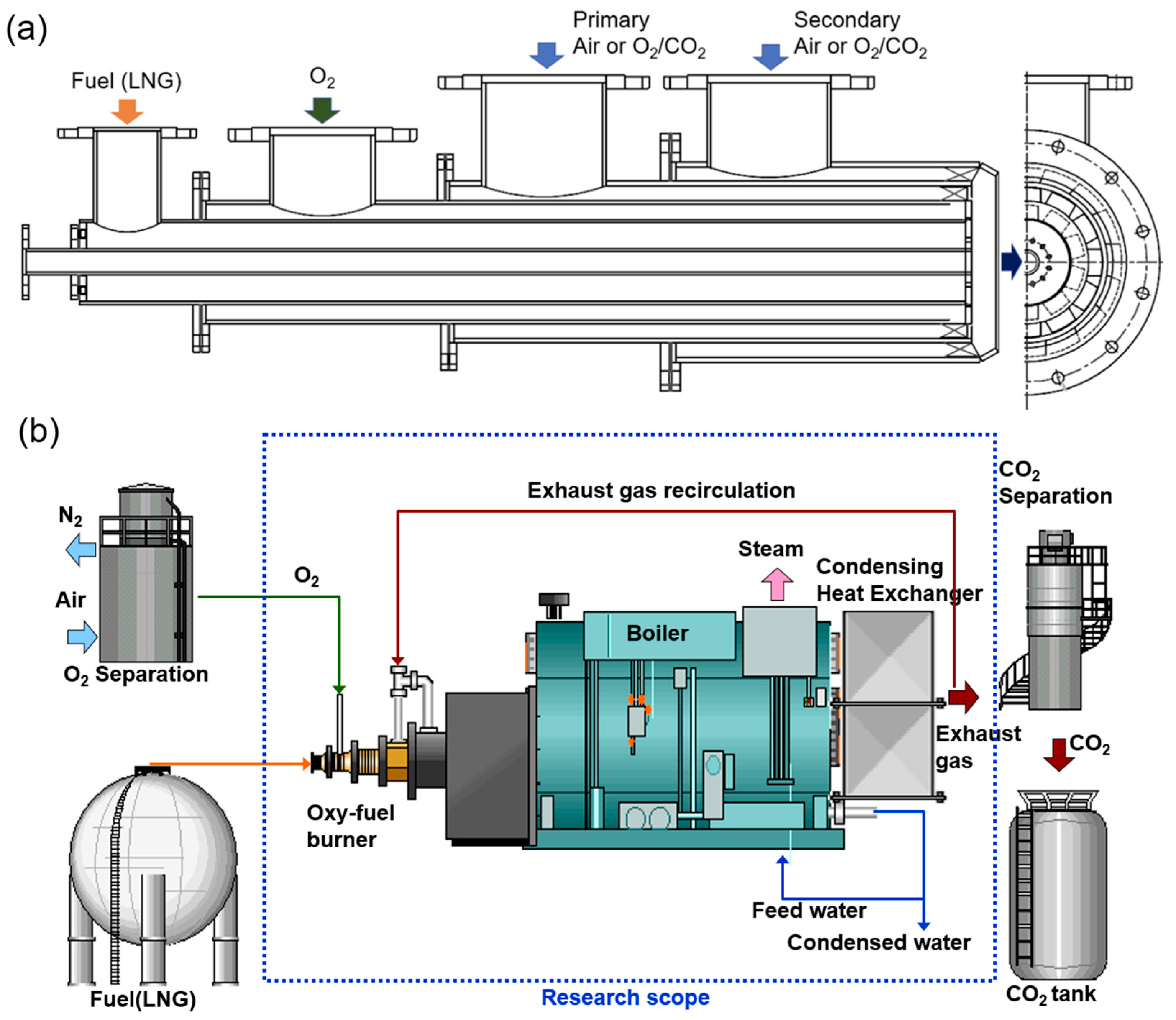
Figure 2.
Experimental setup; (a) schematic diagram; (b) photograph.
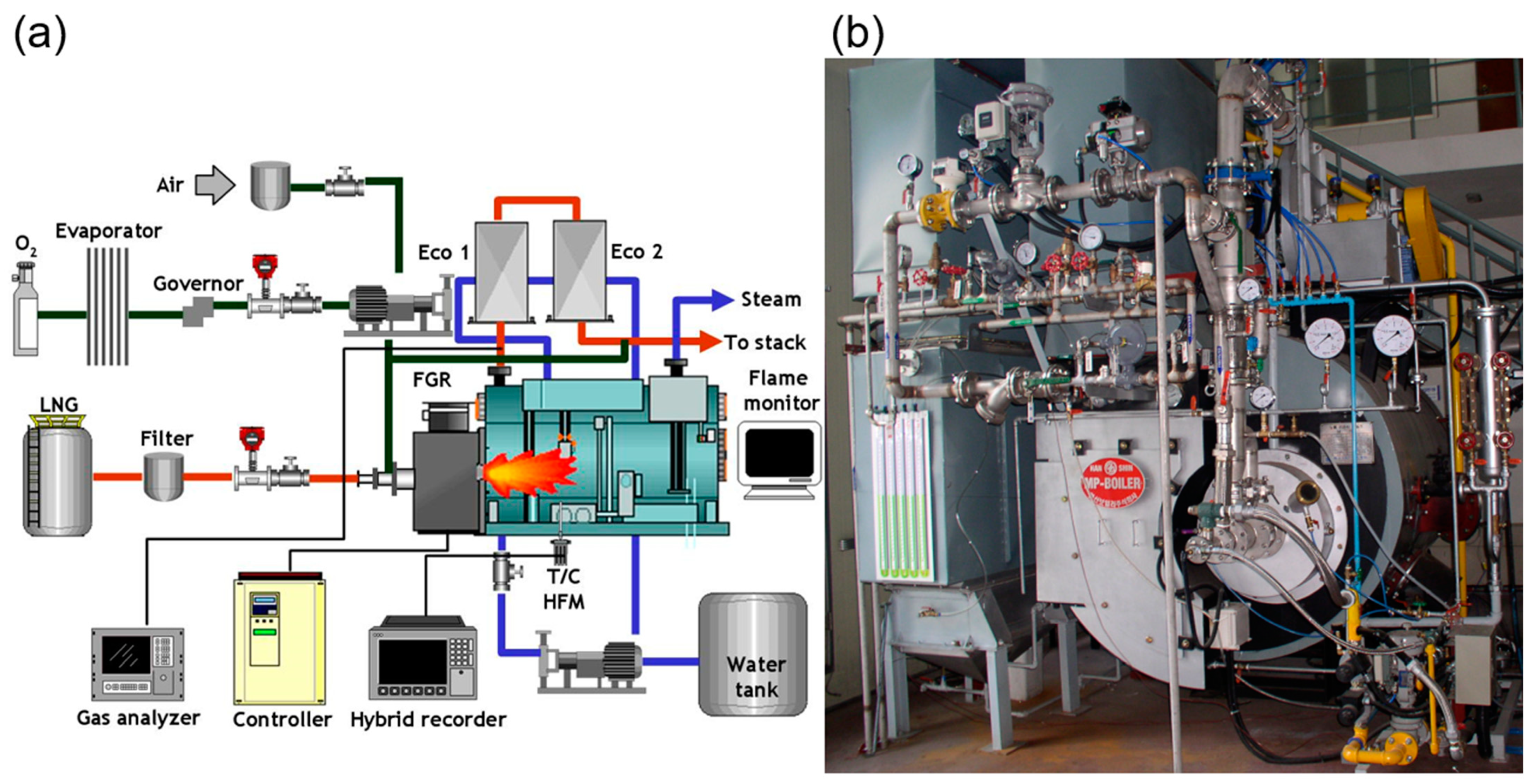
Figure 3.
Flame shape and temperature distribution inside the combustion chamber for each combustion mode: (a) air combustion; (b) oxy-fuel combustion; (c) oxy-fuel FGR combustion.
Figure 3.
Flame shape and temperature distribution inside the combustion chamber for each combustion mode: (a) air combustion; (b) oxy-fuel combustion; (c) oxy-fuel FGR combustion.

Figure 4.
Heat absorbed by each component of the boiler by combustion method: (a) 100% load; (b) 50% load.
Figure 4.
Heat absorbed by each component of the boiler by combustion method: (a) 100% load; (b) 50% load.
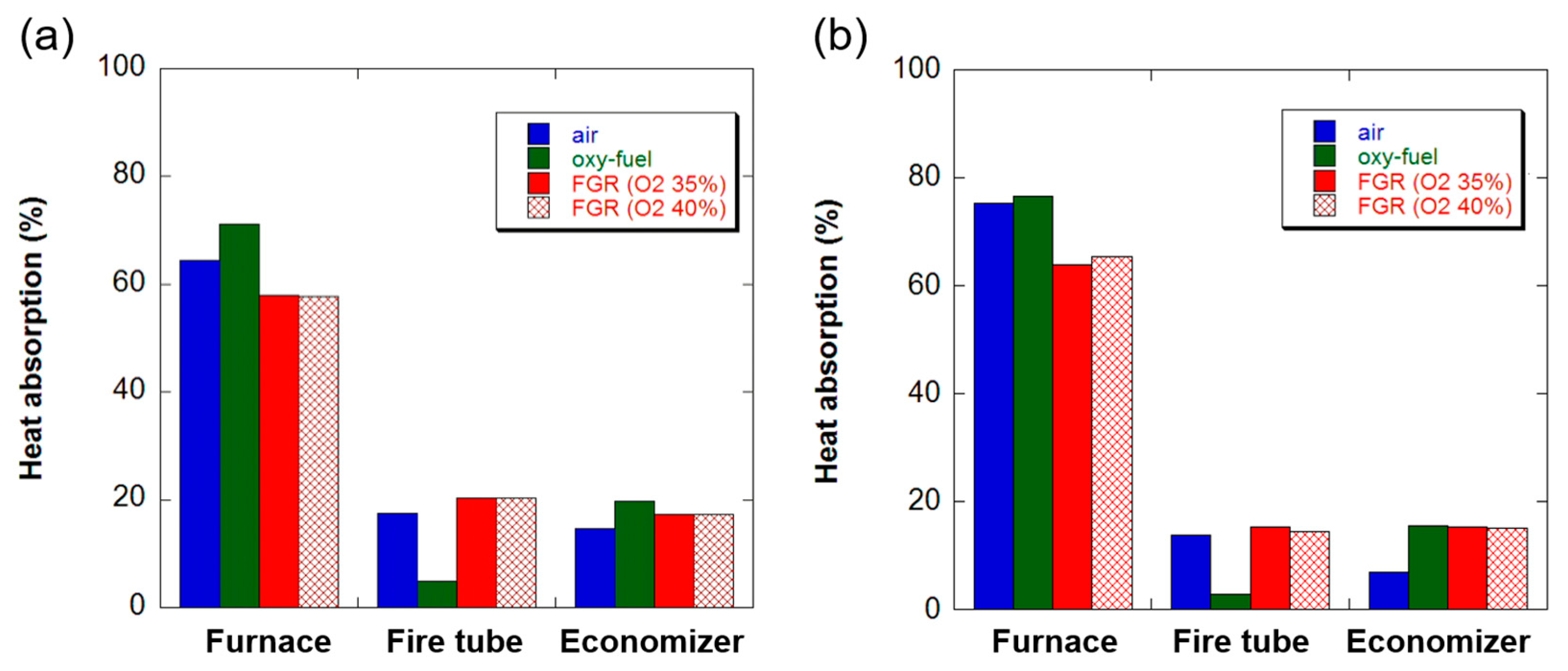
Figure 5.
Thermal efficiency of the boiler by combustion mode obtained by two methods: (a) 100% load; (b) 50% load.
Figure 5.
Thermal efficiency of the boiler by combustion mode obtained by two methods: (a) 100% load; (b) 50% load.

Figure 6.
Heat transfer characteristics in the combustion chamber: (a) exit temperature; (b) flame fullness.
Figure 6.
Heat transfer characteristics in the combustion chamber: (a) exit temperature; (b) flame fullness.

Figure 7.
Heat transfer coefficient inside the fire tube: (a) 100% load; (b) 50% load.
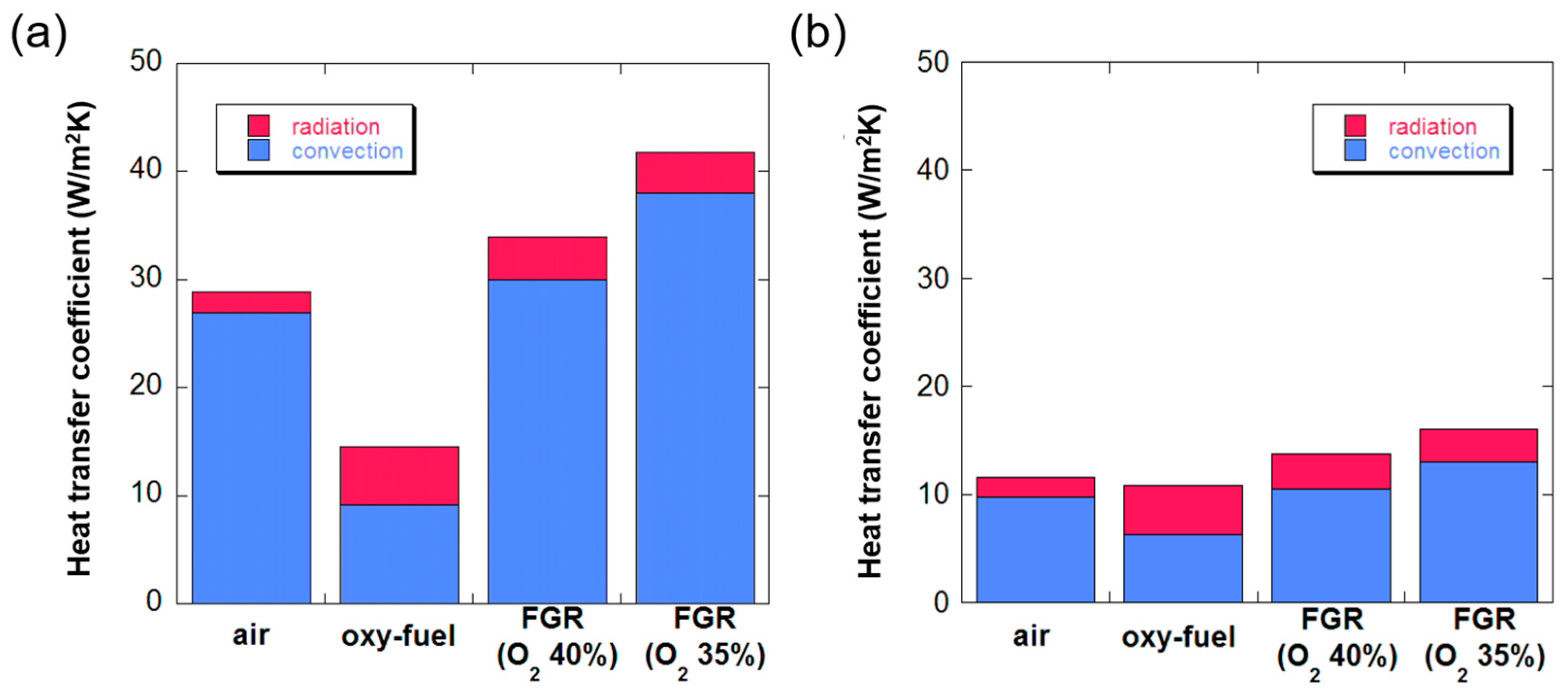
Figure 8.
Nusselt number inside the fire tube: (a) Nusselt number predicted by the Dittus–Boelter equation; (b) Nusselt number ratio.
Figure 8.
Nusselt number inside the fire tube: (a) Nusselt number predicted by the Dittus–Boelter equation; (b) Nusselt number ratio.

Figure 9.
Temperature change at the economizer: (a) temperature drop on the gas side; (b) temperature rise on the water side.
Figure 9.
Temperature change at the economizer: (a) temperature drop on the gas side; (b) temperature rise on the water side.

Figure 10.
Heat exchange efficiency in the economizer: (a) upstream economizer; (b) downstream economizer.
Figure 10.
Heat exchange efficiency in the economizer: (a) upstream economizer; (b) downstream economizer.

Figure 11.
Nusselt number ratio at the economizer: (a) upstream economizer; (b) downstream economizer.
Figure 11.
Nusselt number ratio at the economizer: (a) upstream economizer; (b) downstream economizer.
Disclaimer/Publisher’s Note: The statements, opinions and data contained in all publications are solely those of the individual author(s) and contributor(s) and not of MDPI and/or the editor(s). MDPI and/or the editor(s) disclaim responsibility for any injury to people or property resulting from any ideas, methods, instructions or products referred to in the content. |
© 2024 by the author. Licensee MDPI, Basel, Switzerland. This article is an open access article distributed under the terms and conditions of the Creative Commons Attribution (CC BY) license (https://creativecommons.org/licenses/by/4.0/).
Share and Cite
MDPI and ACS Style
Ahn, J. Heat Transfer and Thermal Efficiency in Oxy-Fuel Retrofit of 0.5 MW Fire Tube Gas Boiler. Processes 2024, 12, 959. https://doi.org/10.3390/pr12050959
AMA Style
Ahn J. Heat Transfer and Thermal Efficiency in Oxy-Fuel Retrofit of 0.5 MW Fire Tube Gas Boiler. Processes. 2024; 12(5):959. https://doi.org/10.3390/pr12050959
Chicago/Turabian StyleAhn, Joon. 2024. "Heat Transfer and Thermal Efficiency in Oxy-Fuel Retrofit of 0.5 MW Fire Tube Gas Boiler" Processes 12, no. 5: 959. https://doi.org/10.3390/pr12050959
Note that from the first issue of 2016, this journal uses article numbers instead of page numbers. See further details here.