
Investigation on Aerodynamic Performance of a Centrifugal Compressor with Leaned and Bowed 3D Blades
by
 ,
,
Zhehong Li
1,2,
Wanmin Kong
3,
Genqiang Shao
3,
Fujian Zhu
3,
Chaowei Zhang
3,
Feiyue Kong
3 and
Yifan Zhang
2,* 1
School of Aeronautical Engineering, Taizhou University, Taizhou 318000, China
2
Wenling Research Institute, Taizhou University, Taizhou 318000, China
3
Zhejiang Mingzhen Electric & Electronic Co., Ltd., Taizhou 317515, China
*
Author to whom correspondence should be addressed.
Processes 2024, 12(5), 875; https://doi.org/10.3390/pr12050875
Submission received: 26 February 2024
/
Revised: 23 April 2024
/
Accepted: 25 April 2024
/
Published: 26 April 2024
(This article belongs to the Section Manufacturing Processes and Systems)
Abstract
:The application of centrifugal compressors is extensive in industries such as aerospace and energy. The blade is the primary factor affecting the aerodynamic performance of compressors. In this paper, the aerodynamic performance of a centrifugal compressor with leaned and bowed 3D blades is investigated. The spanwise section profiles of the blade in the circumferential direction are deflected at different angles, resulting in four compressors with distinct leaned and bowed 3D blades based on the original model. There is a significant change in isentropic efficiency of the modified models under design conditions. Specifically, models 1, 3, and 4 experienced an increase of 0.97%, 1.04%, and 0.79%, respectively, while model 2 experienced a decrease of 0.70%. The profile of the blade tip and 50% spanwise section are shifted towards the suction surface, resulting in a geometric structure where the blade is concave towards the pressure surface. This structure gradually lifts the flow from the blade root to the blade tip downstream to the outlet area of the flow channel, reducing the load on the trailing edge of the blade and making the flow more closely aligned with the blade. At the same time, the larger radial velocity gradient near the blade tip suppresses the backflow on the shroud side, making the flow at the impeller outlet more stable. The outlet velocity of the impeller is more evenly distributed along the spanwise and circumferential directions, which improves the flow at the inlet of the diffuser and enhances the efficiency of the diffuser. Due to the high spanwise height of the leading edge of the blade, this bowed blade structure has little effect on the spanwise curvature upstream of the blade, resulting in negligible influence on the flow of the upstream channel.
1. Introduction
Centrifugal compressors are widely utilized in industries such as energy and various other fields for processing gases. With the advancement of technology, the potential applications of centrifugal compressors are expected to further expand. In particular, the use of centrifugal air compressors in fuel cell systems (FCSs) is crucial for supplying air to the cathode of the fuel cell, directly impacting the overall system efficiency. It is evident that centrifugal air compressors exhibit superior performance in terms of power density, isentropic efficiency, noise, and volume. Therefore, they are expected to be the dominant direction for the development of specialized air compressors in FCSs [1]. To evaluate the aerodynamic excitation, analyzing aerodynamic noise based on external acoustic field measurements could be a viable approach. The experimental measurements covered the entire operational range of the selected centrifugal compressor [2,3].
Currently, researchers are focused on improving the performance of centrifugal compressors by optimizing blade geometry parameters such as camber, thickness, angle, and profile shape, which directly impact their aerodynamic characteristics [4]. A well-designed blade geometry can significantly enhance the efficiency of a centrifugal compressor. Traditionally, researchers have primarily concentrated on optimizing blade load. The orientation of the trailing edge of the blade, whether it is backward- or forward-inclined in relation to the leading edge, plays a crucial role in load distribution [5]. Bednarz et al. [6] demonstrated that the baseline design fell within the optimal range of thrust-specific fuel consumption. However, increasing the number of blades resulted in an aerodynamic loading crisis at the splitters, preventing further increase in the pressure ratio. The blade count has the most significant influence on the compressor’s performance, and the blade angle at the inlet is also of great importance [7]. By comparing the optimized model to the original model, a remarkable 16% reduction in entropy increase and a 1.3% increase in adiabatic efficiency were observed [8]. Hiradate et al. [9,10] discovered that designing the blades with a tilt direction opposite to the impeller rotation led to a substantial alteration in the static pressure distribution within the impeller.
Computational fluid dynamics (CFD) is widely utilized for analyzing the flow field and optimizing the performance of centrifugal fans [11,12]. An interesting finding revealed that the dominant patterns of jet-wake flow were caused by vortex and blade channel blockage, resulting in high velocities on the pressure side of the blade [13]. The orthogonal method has also been employed to improve the number of blades, manufacturing parameters of fan blades, and aerodynamic performance of fans [14,15]. Xu et al. [16] investigated the impact of different blade tilt angles on the performance of centrifugal compressors. Among the tested tilt angles, the negative tilt angle demonstrated the highest peak efficiency, albeit with the highest-pressure load. Optimization algorithms play a crucial role in enhancing the performance of centrifugal compressors. By integrating multi-objective parameter optimization with the Kriging model, an optimal model has been obtained [17].
The aforementioned study primarily examined the utilization of blade load and the trailing edge of centrifugal compressor blades to enhance performance. Several designs have been proposed, including magnetically levitated compressors with forward-curved blades and radial flow compressors with straight blades [18]. Efficiency and pressure ratios are influenced by various factors, such as the velocity coefficient, energy head coefficient, rotational speed, blade height, inlet radius, and radial distance [19]. A comparative study of different blade types revealed that impellers with a trailing edge bend opposite to the rotating direction reduced the pressure difference near the blade tip, thereby minimizing tip leakage loss and improving compressor performance [20].
The decrease in aerodynamic performance of compressors is primarily attributed to flow loss, and researchers have explored various approaches to mitigate this issue and improve compressor performance. Fan et al. [21] discovered that cracked blades exhibit a significant deviation in natural frequency compared to intact blades, highlighting the impact of cracked blades on the overall blade system. Jang et al. [22] utilized a response surface analysis to optimize blade sweep, tilt, and bend structures, resulting in reduced leakage loss at the blade tip and improved overall compressor performance. The influence of blade inclination angle on high-pressure ratio centrifugal compressors cannot be overlooked [23]. A positive inclination at the outlet reduces wake loss, but excessive inclination limits the operational range [23].
We hold the opinion that increasing the blade outlet angle and raising the impeller outlet height to enhance the relative velocity diffusion ratio between the impeller inlet and outlet can effectively reduce losses in the diffuser channel and prevent a decrease in the pressure ratio. This paper investigates the aerodynamic performance of a centrifugal compressor with leaned and bowed 3D blades. The section profiles of the blades are deflected at different angles in the circumferential direction, resulting in four compressors with distinct leaned and bowed 3D blades based on the original model. Under design conditions, there was a notable change in the isentropic efficiency of the modified models. Specifically, models 1, 3, and 4 experienced an increase of 0.97%, 1.04%, and 0.79%, respectively, while model 2 experienced a decrease of 0.70%. A comparison of the velocity distributions at the impeller outlet revealed that the velocity distribution of the new impeller was much more uniform than that of the original one. The leaned and bowed 3D blades primarily modified the spanwise curvature of the blade. When the entire blade height profile was rotated at a certain angle along the rotating axis of the impeller, the curvature of the leading edge of the blade underwent little change due to the large spanwise height of the blade’s leading edge. As a result, there was minimal influence on the upstream flow. Conversely, the longitudinal height of the blade’s trailing edge was smaller, leading to a relatively greater structural variation at the trailing edge. Consequently, both the downstream and outlet flows within the blade channel were significantly affected.
2. Geometry and Numerical Methodology
The computational domains of the centrifugal compressor are depicted in Figure 1. As illustrated in Figure 1a, the computational domain comprised an impeller along with an inlet and outlet for the compressor. The meridian plane of the compressor is illustrated in Figure 1b, where the flow entered the blade passage through the vaneless diffuser. Table 1 shows the main parameters of the compressor [24,25].
The computational fluid dynamics (CFD) method is based on the fundamental control equations of fluid dynamics: the continuity equation, momentum equation, and energy equation. These equations are derived from the physical laws of mass conservation, Newton’s second law, and energy conservation, respectively:
where ρ is the fluid density, u is the velocity, fb is the body force, τ is the surface stress, q is the quantity of heat, and T is the temperature. In this study, Ansys CFX18.0 software was employed to simulate the three-dimensional steady flow field of the compressor. The working fluid is compressible fluid. The based Shear-Stress-Transport (SST) model was designed to give highly accurate predictions of the onset and the amount of flow separation under adverse pressure gradients by the inclusion of transport effects into the formulation of the eddy viscosity. This results in a major improvement in terms of flow separation predictions. The superior performance of this model has been demonstrated in a large number of validation studies. The SST model is recommended for accurate boundary layer simulations. For free shear flows, the SST model is mathematically identical to the model. The SST turbulence model was utilized, and the equations are as follows:
The equations along with appropriate boundary conditions are solved numerically to obtain the distribution of turbulent kinetic energy (k) and specific dissipation rate (ω) throughout the computational domain of the SST turbulence model. In the equation, the turbulent kinetic energy Gk is generated by the laminar velocity gradient, and Gω is produced by the omega equation. The terms Γk and Γω represent the diffusion rates of k and ω, respectively, while Yk and Yω represent the turbulence caused by diffusion. The diffusion term equations are as follows:
where σk and σω are the turbulent Prandtl numbers for the k and ω equations, respectively. The inlet boundary condition is defined by uniform temperature and total pressure. The outlet boundary enforces the mass flow condition. Additionally, the wall boundary is subject to non-sliding and adiabatic conditions. The second-order upwind scheme was utilized for spatial discretization of the convection term, while the diffusion term was discrete using a central difference scheme with second-order accuracy. The coupling between velocity and pressure is achieved by employing the SIMPLE algorithm. As shown in Figure 2, the wall y+ of the blade was under 10, as shown in the following picture. The figures of grid details near the wall are also shown as follows.
As show in Table 2, the number of cells is 0.77 × 10⁶, 1.17 × 10⁶, 1.67 × 10⁶, and 2.46 × 10⁶, respectively. Total pressure was used as a criterion for grid independence verification.
The impeller was characterized by a periodic grid, with each blade section divided according to this periodicity. The computation results for total pressure show variations depending on the number of cells employed, as illustrated in Figure 3. The simulated total pressure values approached the experimentally obtained results as the number of cells increased. When the total number of cells reached 2.46 × 10⁶, there was only a 1% deviation between the numerical simulation and experimental results for the total pressure ratio under the design condition (Q = 2.55 kg/s). Therefore, this study used 2.46 × 10⁶ grids in the numerical calculation of the stationary flow. This number of grids had a good calculation cost and could predict the flow characteristics of the fan well.
In addition to grid-independence verification, the simulation results of the original model were compared with the experimental results. The comparison between the experimental result and the numerical simulation of the original blade model is depicted in Figure 4. The difference between the numerical and experimental results was less than 5%. The discrepancy was observed at the maximum flow operating point from comparing experimental results obtained from full-flow channels with calculations conducted on single flow channels in this study. The aforementioned error, however, did not impact the research of this paper as its primary focus lies in optimizing the design operating condition.
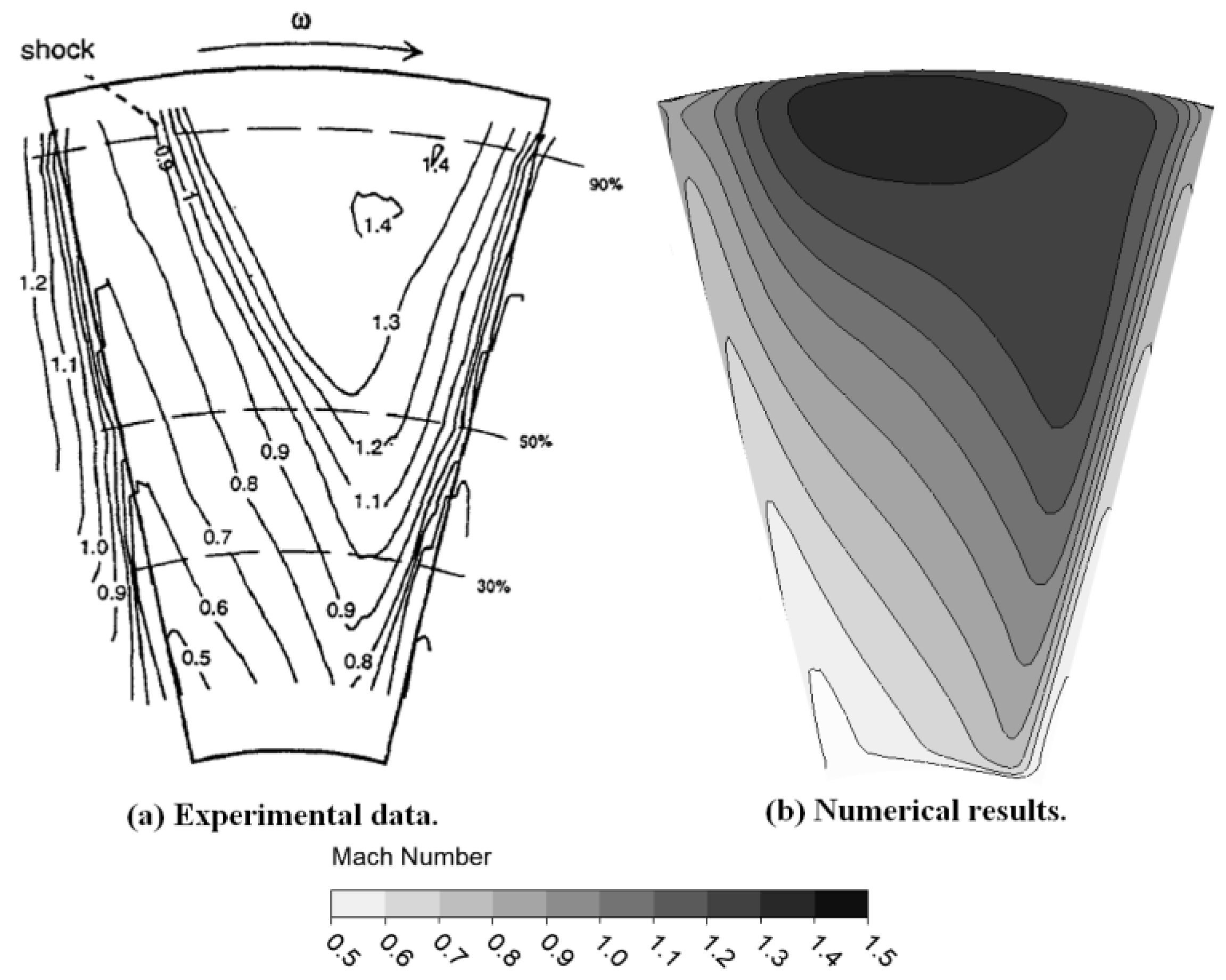
Figure 5 presents a comparison of the Mach number at the impeller inlet for the design condition (Q = 2.55 kg/s), where the Mach number distribution primarily ranged between 0.5 and 1.5. The computed Mach number distribution showed good agreement with the experimental results reported in the literature [24,25]. As shown in Figure 6, at the design condition, the Mach number comparison at the impeller outlet was mainly between 0.4 and 0.8. The suction and pressure sides of the main blade, near the splitter blade, exhibited distinct Mach number distribution characteristics, which were consistent with experimental results found in the literature. In summary, the comparison and validation of computational results for both external characteristics and flow field details of the compressor against experimental results demonstrated that the numerical results for external performance and flow details were in good agreement with experimental data, indicating the validity of the numerical solution method used in this study.
3. Numerical Results and Discussions
The overall efficiency of a centrifugal compressor is defined as the ratio of the actual work exerted on the gas to the ideal work. It can be broken down into several components, including mechanical, adiabatic, and volumetric efficiency. Higher centrifugal compressor efficiency results in lower power consumption. When the compressor is more efficient, it requires less energy input to deliver the desired mass flow rate. This can lead to energy savings and reduced operating costs. Centrifugal compressor efficiency also affects the mass flow rate. A more efficient compressor can handle a higher mass flow rate for a given power input. This means that as the efficiency increases, the compressor can compress and deliver a larger volume of gas per unit of time. It is important to note that the efficiency of a centrifugal compressor is influenced by various factors, such as design parameters, operating conditions, and maintenance. Optimizing these factors can help improve compressor efficiency, resulting in more cost-effective and higher-performance operations.
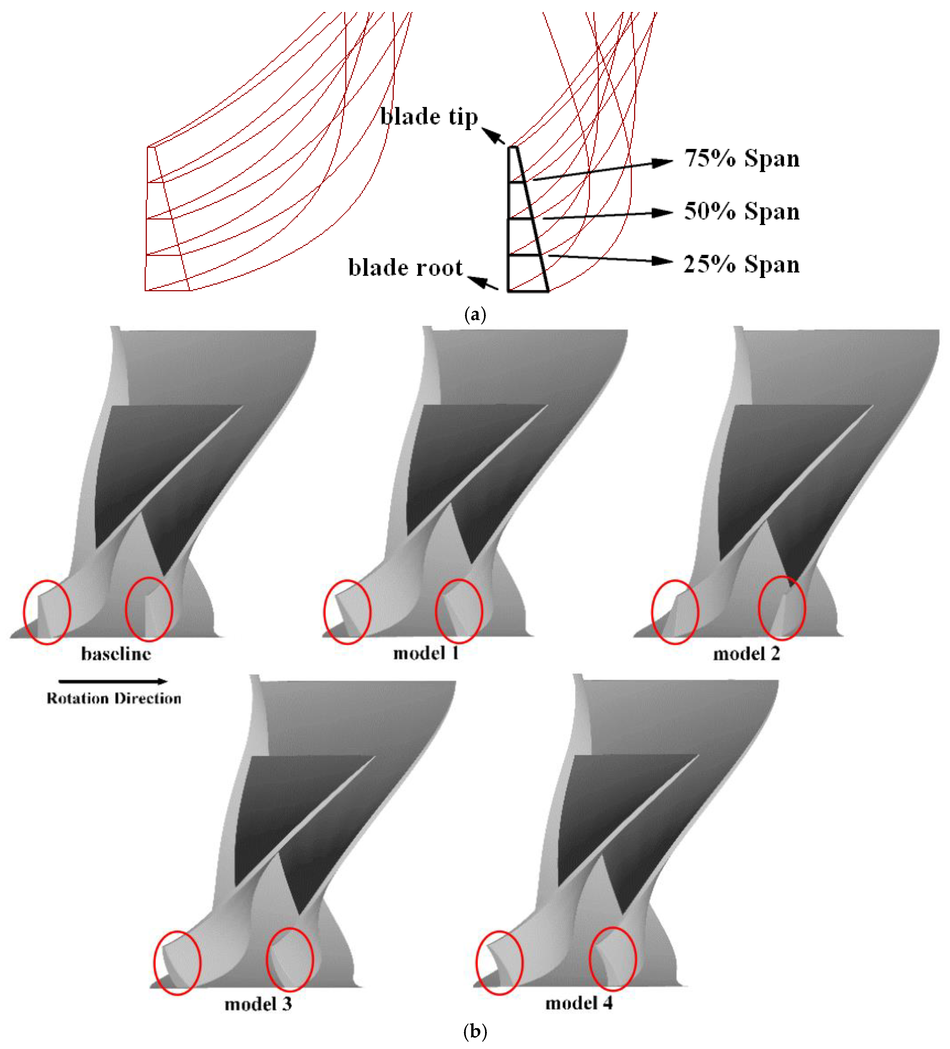
The schematic diagram of each section in the transverse direction of the blade is depicted in Figure 7a. In accordance with the original model, the sections of both the main blade and splitter blade exhibited deflections at varying angles along the circumferential direction. The deflection angle was defined as positive when the circumferential deflection direction opposed the impeller rotation direction, and four blades with different deflection angles could be obtained. The blade tip section was deflected by +2° and −2° in models 1 and 2, respectively, while the blade root section remained unchanged. The remaining sections conformed to the deflection angle to maintain a straight trailing edge of the blade. The deflection of the tip section of models 3 and 4 at +2° served as the basis for deflecting the section at 50% leaf height by +0.5° and −0.5°, respectively. The modified geometry of the four models is illustrated in Figure 7b.
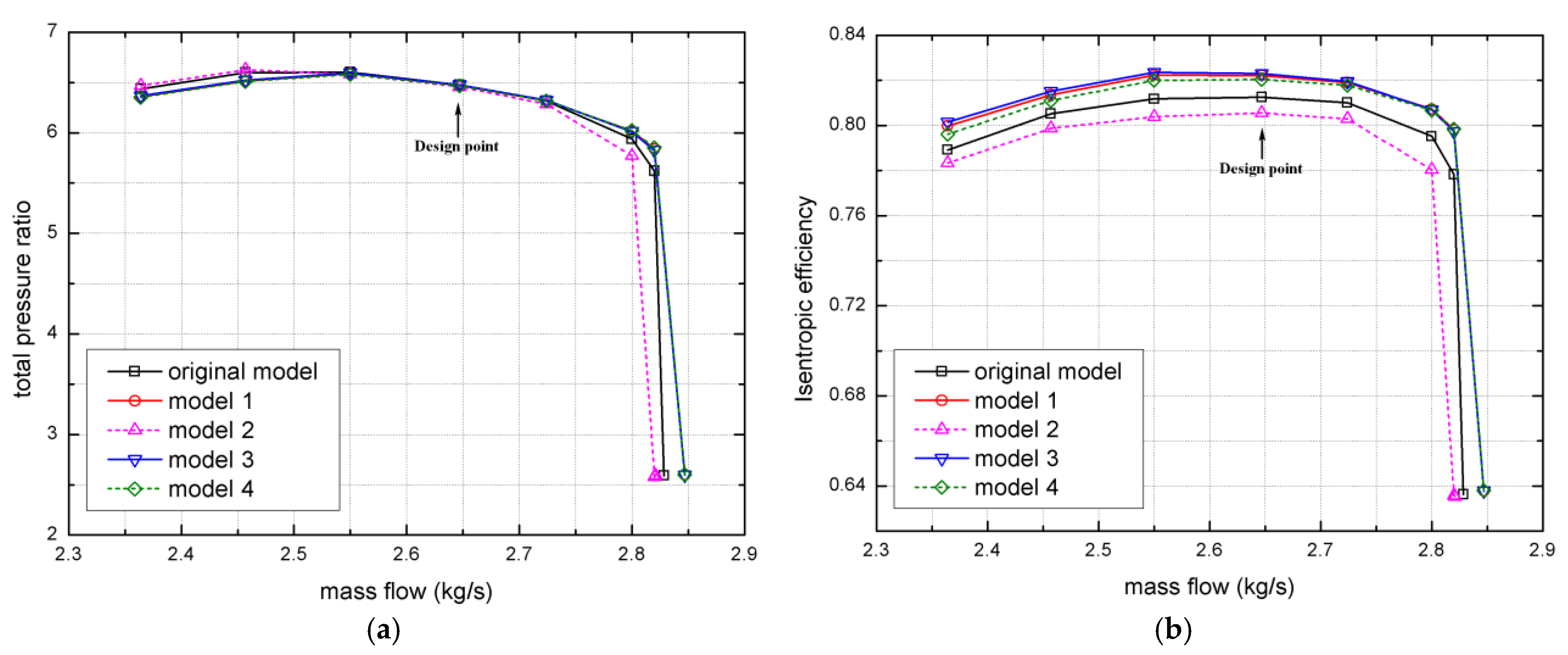
The total pressure ratio of the modified models under the design condition remained relatively unchanged, as depicted in Figure 8. However, there was a significant variation in isentropic efficiency. Specifically, models 1, 3, and 4 exhibited an increase of 0.97%, 1.04%, and 0.79%, respectively, while model 2 experienced a decrease of 0.70%. Under low flow conditions, the total pressure ratio of model 2 remained nearly unchanged; however, its isentropic efficiency experienced a significant decrease. Conversely, models 1, 3, and 4 exhibited notable improvements in their isentropic efficiency when there was a slight reduction in the total pressure ratio. The total pressure ratio and isentropic efficiency of models 1, 3, and 4 were enhanced under high flow conditions, whereas model 2 experienced a significant decrease. The high flow conditions of models 1, 3, and 4 exhibited an expanded range, while model 2 experienced a slight reduction. Model 3 demonstrated the best overall performance, whereas model 2 performed the worst. Consequently, a subsequent analysis will primarily focus on comparing and examining the internal flow field differences between the original model and models 2 and 3 under the design condition.
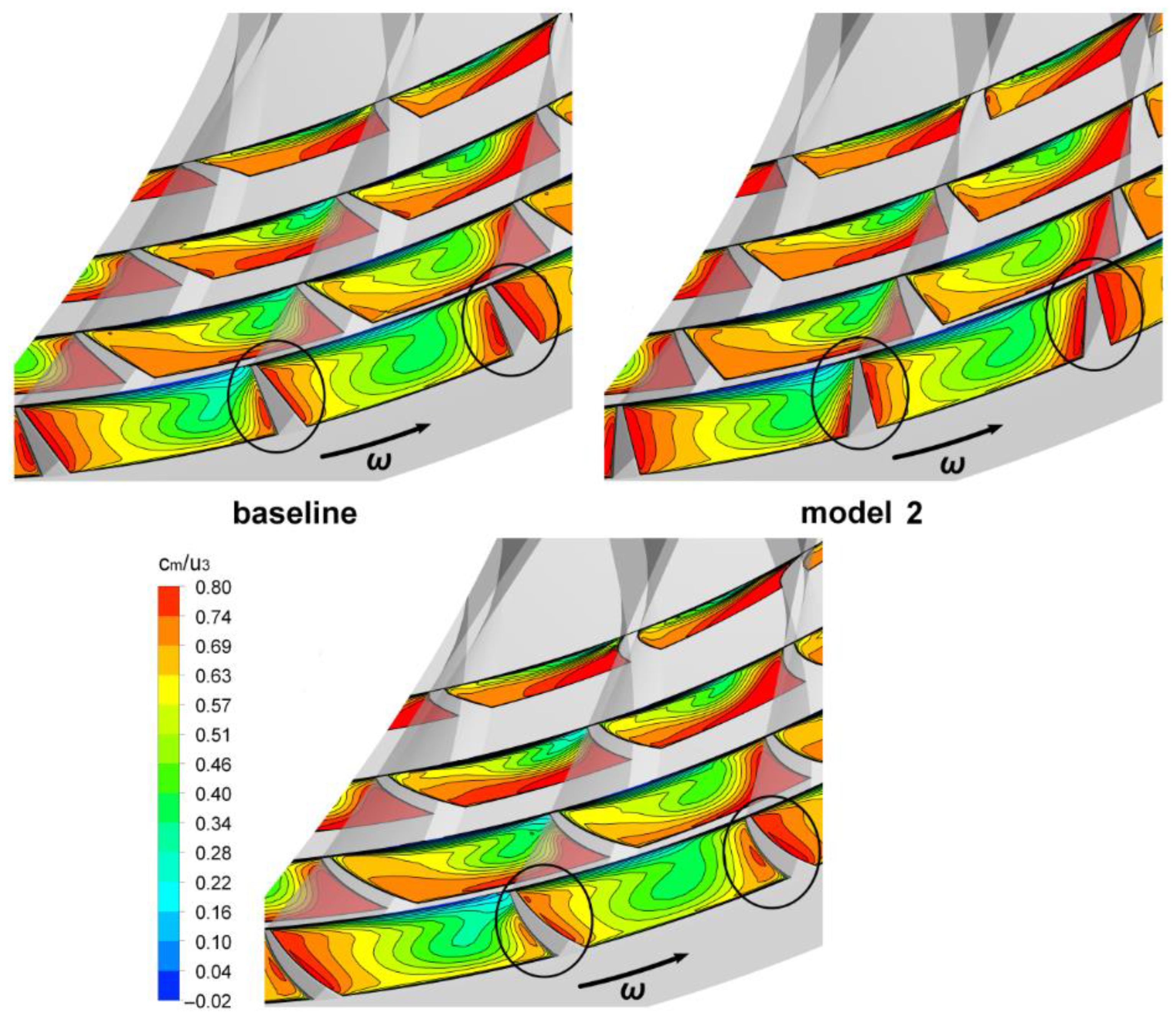
Figure 9 illustrates the dimensionless meridian velocity distribution of multiple sections from the downstream to the outlet of the impeller. In the original model, the high-speed region was mainly concentrated on the blade suction surface and near the wheel. However, as the blade width to height ratio increased, this high-speed region shifted from the wheel towards the blades. Eventually, a high-speed region formed on both sides of the blade at the impeller outlet, with slightly lower speeds observed on both sides of the splitter blade compared to that on the main blade. There was a thin, low-speed reflux region on one side of the casing within the flow channel, and the changes in the meridian velocity distribution within this channel were mainly concentrated between sections c and d. Due to tilting towards the rotation direction, the increased angle between the pressure surface and wheel led to a larger high-speed area on one side of the pressure surface for each blade. As a result, a higher speed and wider range high-speed region emerged on both sides of each blade at the impeller outlet. In model 3, where the blades tilted against the rotation direction, causing suction-side convexity and pressure-side concavity due to bending effects, there was a reduction in range and speed for the high-speed region along the suction surface at the impeller outlet. Growth inhibition was observed for the high-speed region along the pressure surface, resulting in similar but lower speeds compared to those of the original model across both sides of each blade. Additionally, there was a slight reduction observed in the return flow region adjacent to the casing.
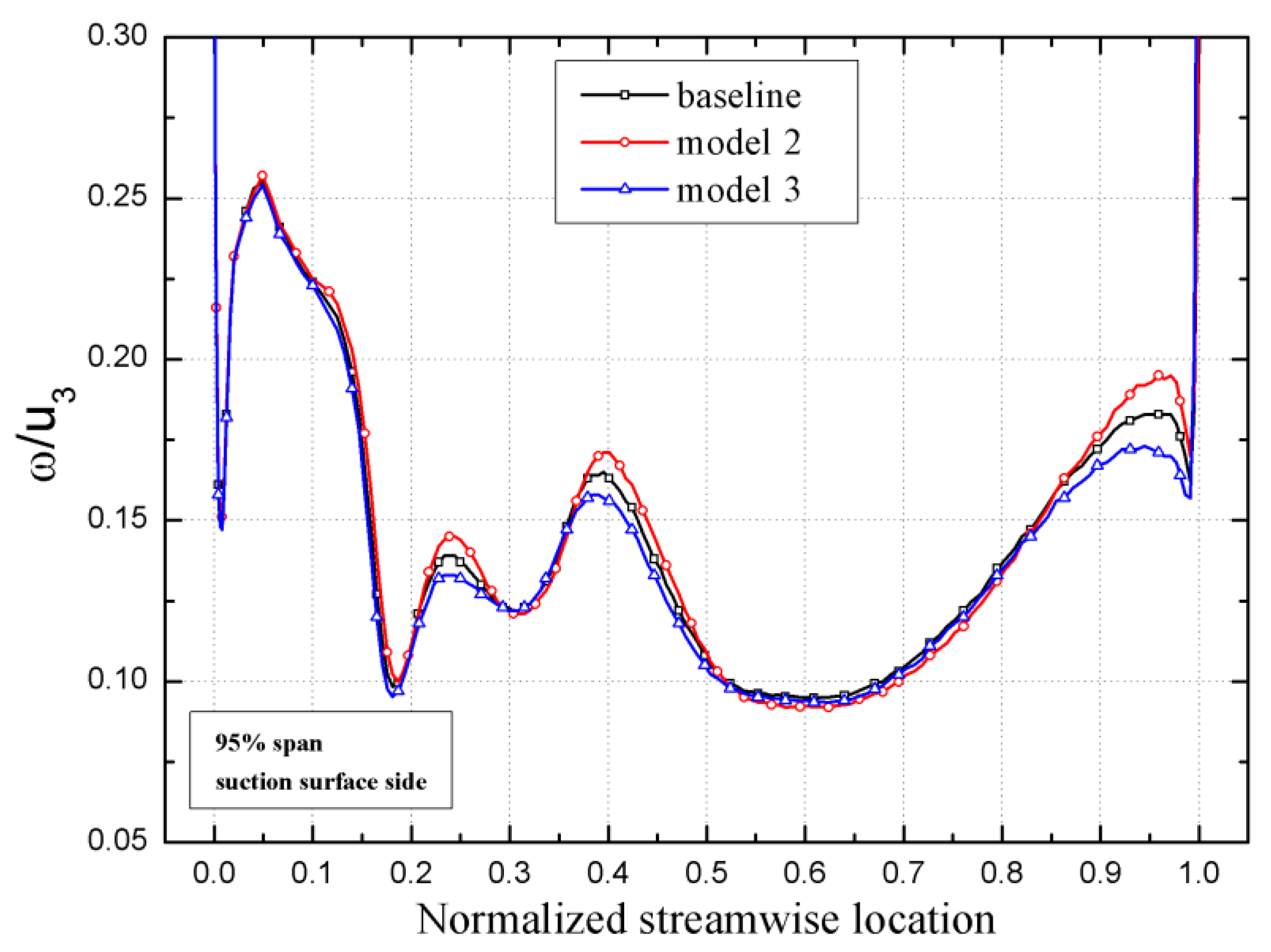
The comparison diagram shown in Figure 10 depicts a dimensionless relative velocity distribution on the main blade high-suction surface of 95%. The differences in relative velocity distribution among the three models were mainly concentrated within the flow direction range of 0.2–0.5 and 0.9–1. The relative velocity fluctuated within a specific range, with the largest difference occurring at wave peaks. Model 2 exhibited the highest level of fluctuation, while model 3 showed minimal fluctuation. In general, model 3 demonstrated a more evenly distributed relative velocity along the blade passage.
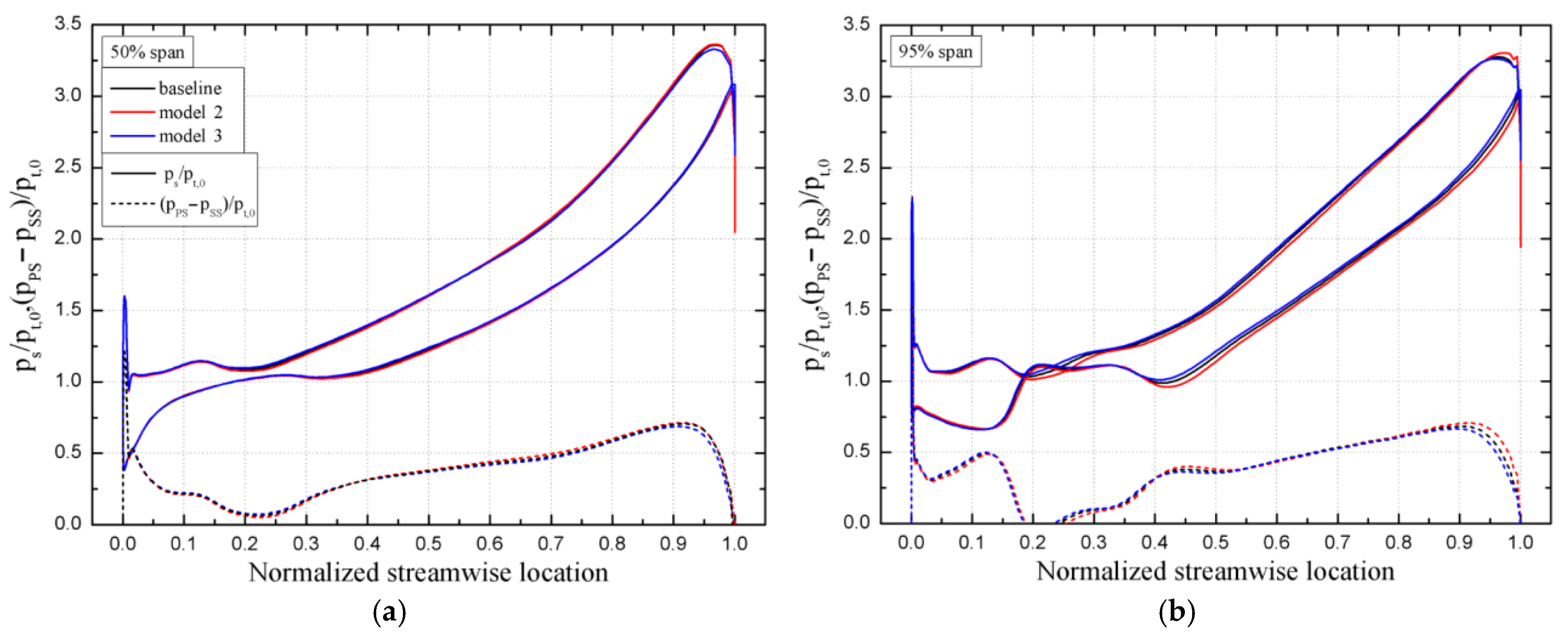
Figure 11 shows the non-dimensional load distribution on the main blade surface at 50% and 95% blade height. At a blade height of 50%, all three models exhibited a similar trend in load distribution, with the pressure difference between the two sides of the blade gradually increasing towards its maximum value in the downstream region. However, at a blade height of 95%, noticeable differences in load distribution were observed in the downstream region. Model 3 showed the smallest pressure difference between both sides of the blade. Additionally, model 3 demonstrated a more gradual attenuation trend for pressure differences near the trailing edge of the blade.
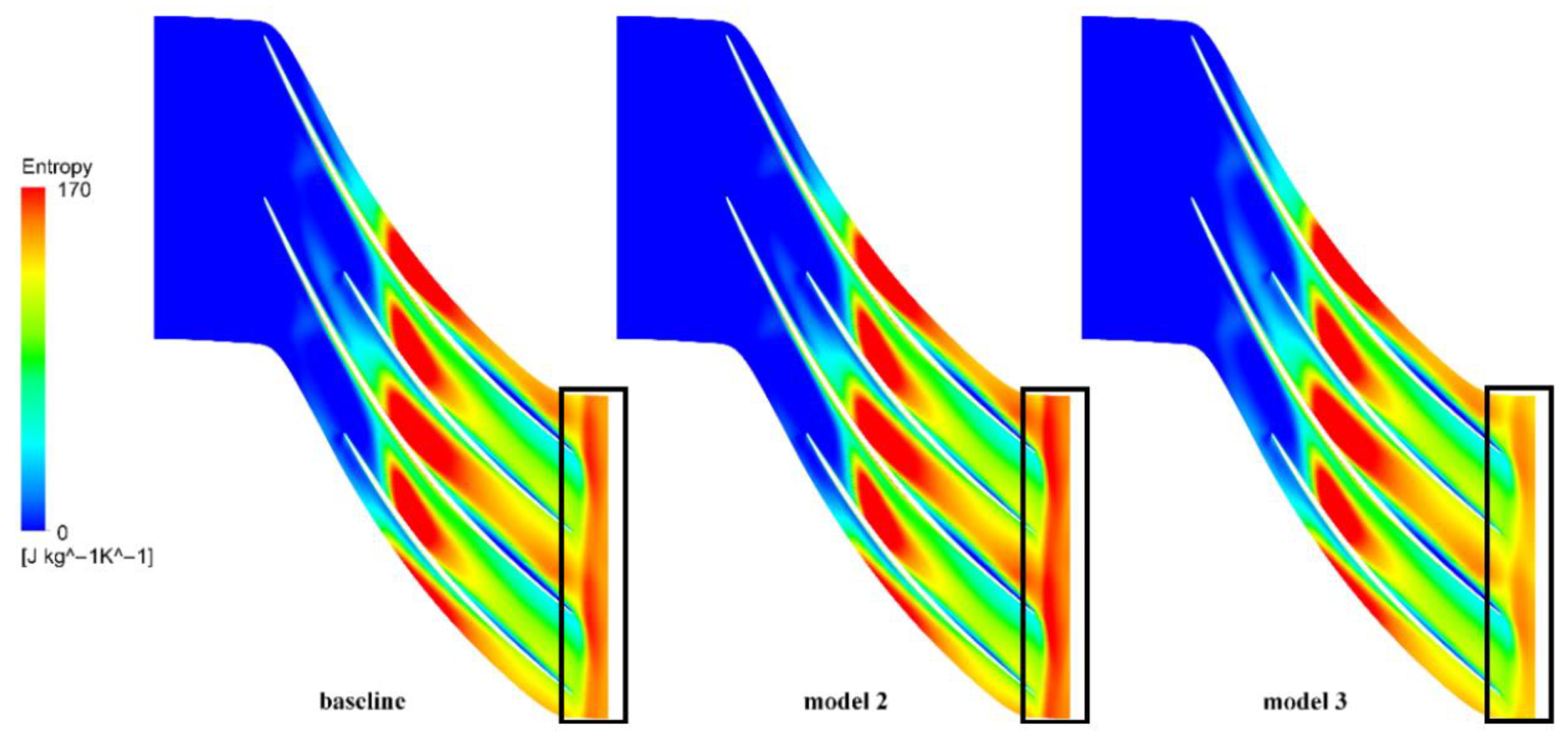
Figure 12 illustrates the internal entropy distribution of the flow channel at a 95% blade height section. The regions with the highest entropy among the three models were mainly located in the middle of the flow channel, gradually decreasing downstream. Furthermore, there was a slight increase in entropy at the impeller outlet, with model 2 exhibiting the highest entropy, while model 3 showed a significant reduction compared to that of the original model. From the above analysis of the flow field in the impeller along the flow direction, it can be seen that the different deflection angles of the blades mainly affected the flow downstream of the blade passage near the impeller outlet.
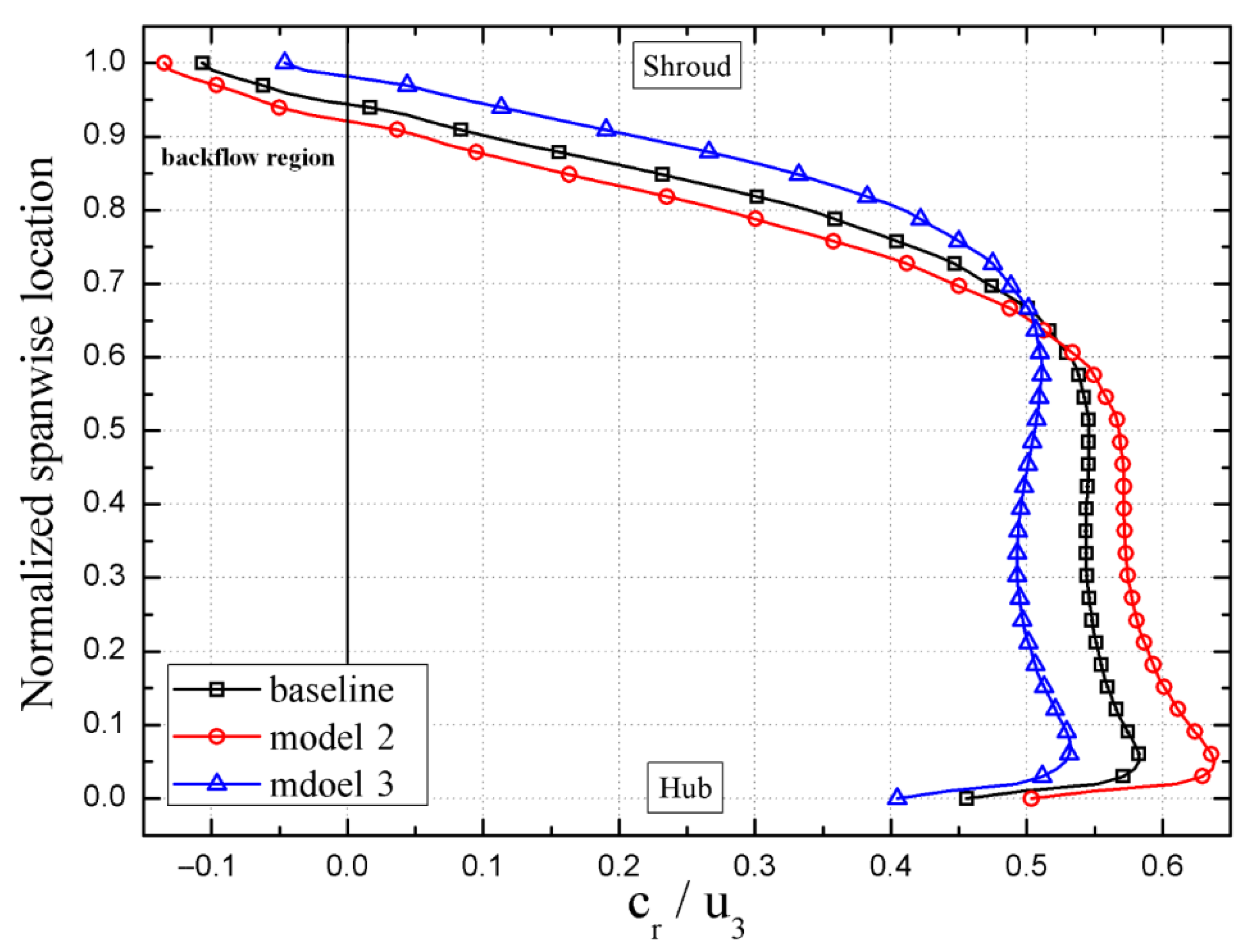
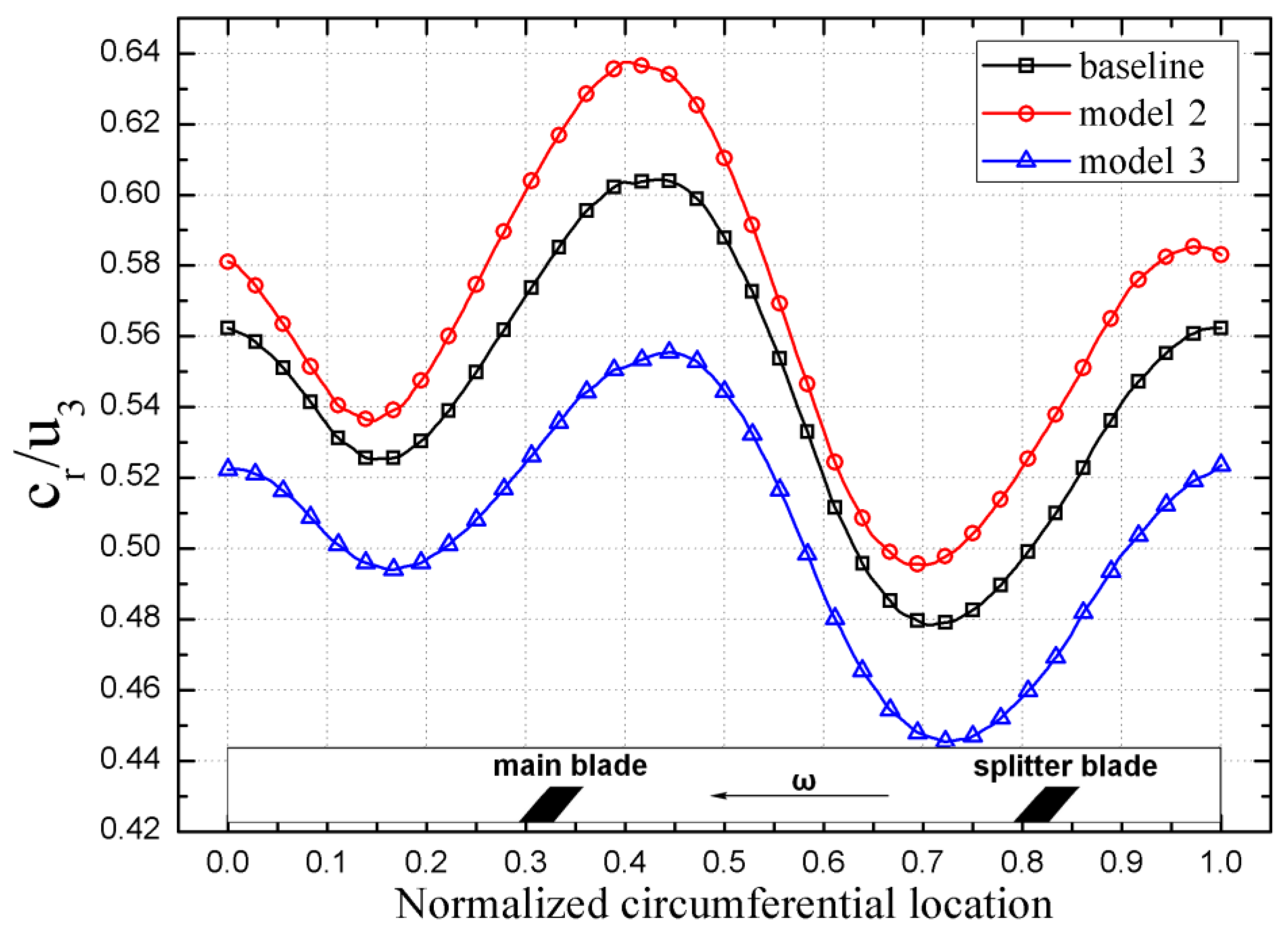
Figure 13 illustrates the distribution of the dimensionless radial velocity (average circumferential mass) at the impeller outlet along the spanwise direction. In the tip clearance region, all three models exhibited a backflow region. However, model 3 exhibited a smaller backflow region with lower backflow speed compared to that of the original model, while model 2 showed the opposite trend. The radial velocity of model 3 experienced a significant increase from 65% to 95% of the blade height, eventually reaching relative stability. Subsequently, the values gradually decreased and became more uniformly distributed in the spanwise direction. As shown in Figure 14, model 3 displayed a narrower fluctuation range in the circumferential direction and an overall more uniform distribution of radial velocity at the impeller outlet. This had a significant impact on flow stability when the fluid entered the vaneless diffuser.
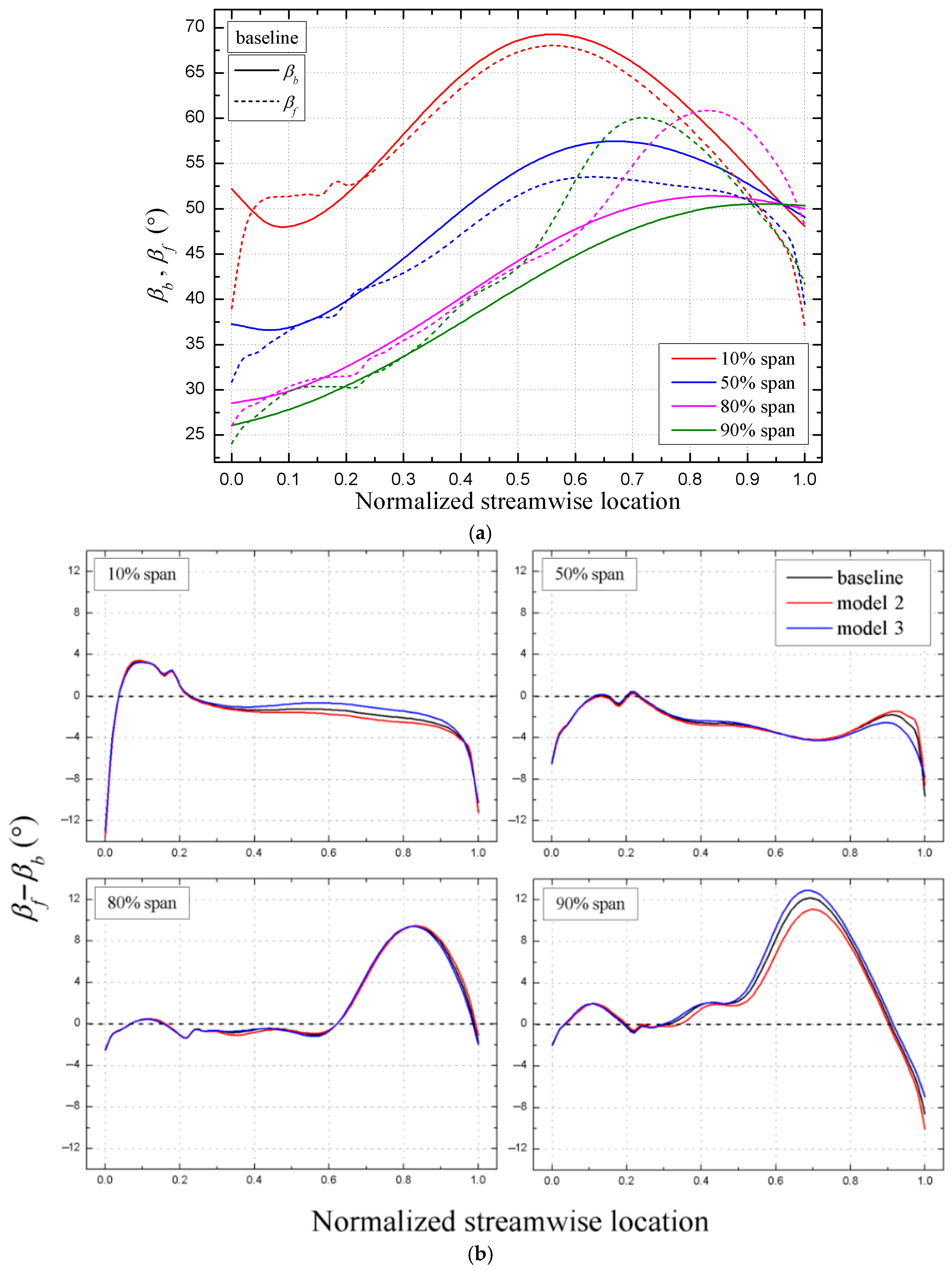
Figure 15a illustrates the distribution of blade angles and relative airflow angles along the flow direction in the original model. The figure shows that the blade angle of the original model had a uniform distribution at different blade heights. In the upstream region of the flow channel, there was a slight disparity between the relative airflow angle and blade angle, primarily noticeable in the lower section (10–50% span) of the blade height. Downstream, there was a significant increase in difference between the relative airflow angle and blade angle for the high blade height (80–90% span). At the outlet of the flow channel, except for a high blade height of 80% span, the discrepancy between the relative airflow angle and blade angle further escalated. The analysis of the variation between the blade angle and relative airflow angle for all three models at each specific blade height, as depicted in Figure 15b, indicated that the disparities primarily manifested within the intermediate to lower regions of the flow channel at a 10% span position. Model 3 demonstrated a minimal difference, indicating greater stability in its flow behavior during this period compared to those of the other models. The differences among all three models rapidly increased near the outlet region of the flow channel. However, model 3 exhibited the least change between its respective values for both angles compared to the other models. The difference among the three models was minimal at a blade height of 80%, while it exhibited significant fluctuations in the middle and downstream regions of the flow channel at a blade height of 90%. The reduction in the discrepancy between the blade angle and relative flow angle in the vicinity of the flow channel outlet of model 3 signified that the bending structure could effectively impede flow separation at said outlet, thereby further impacting efficiency.
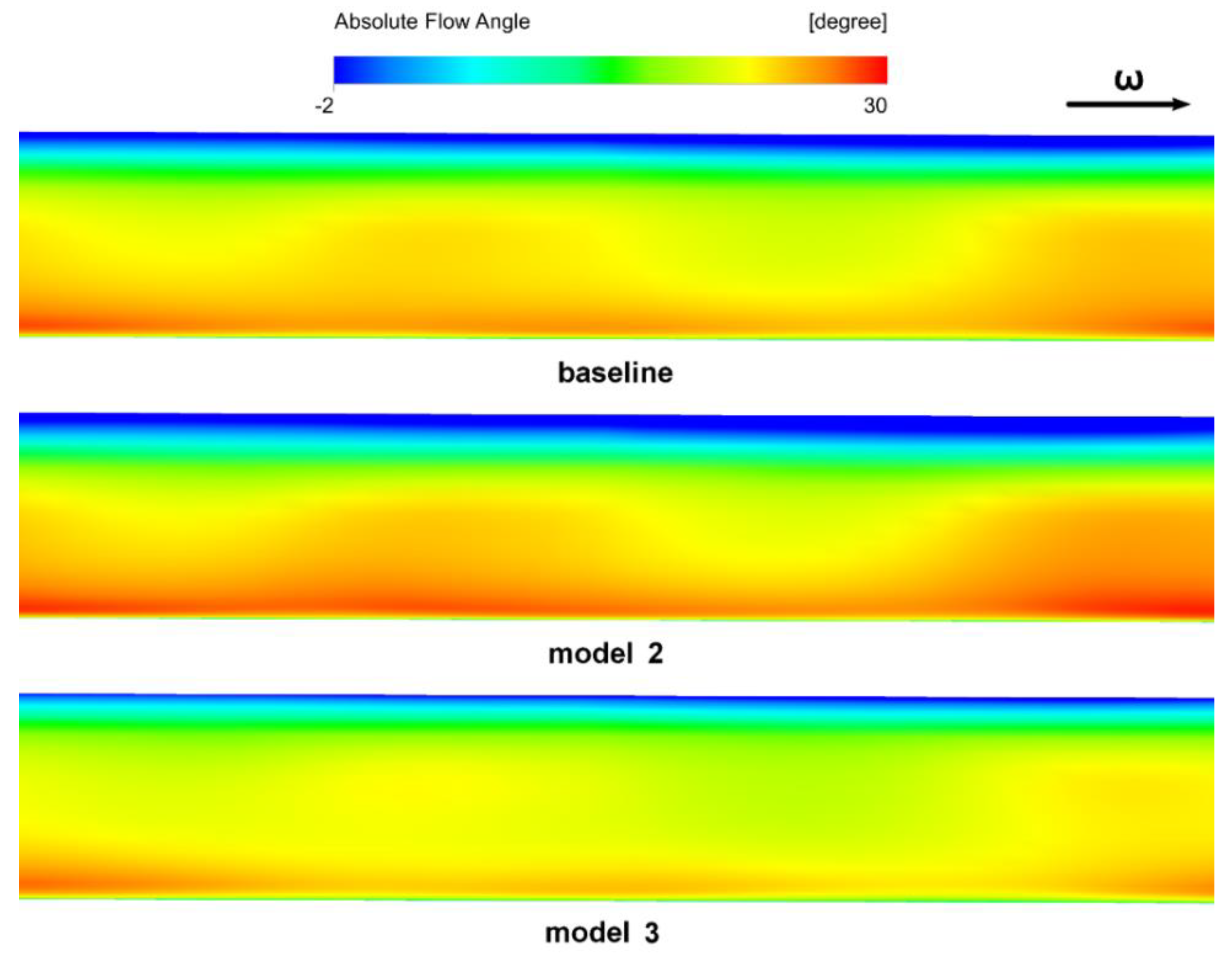
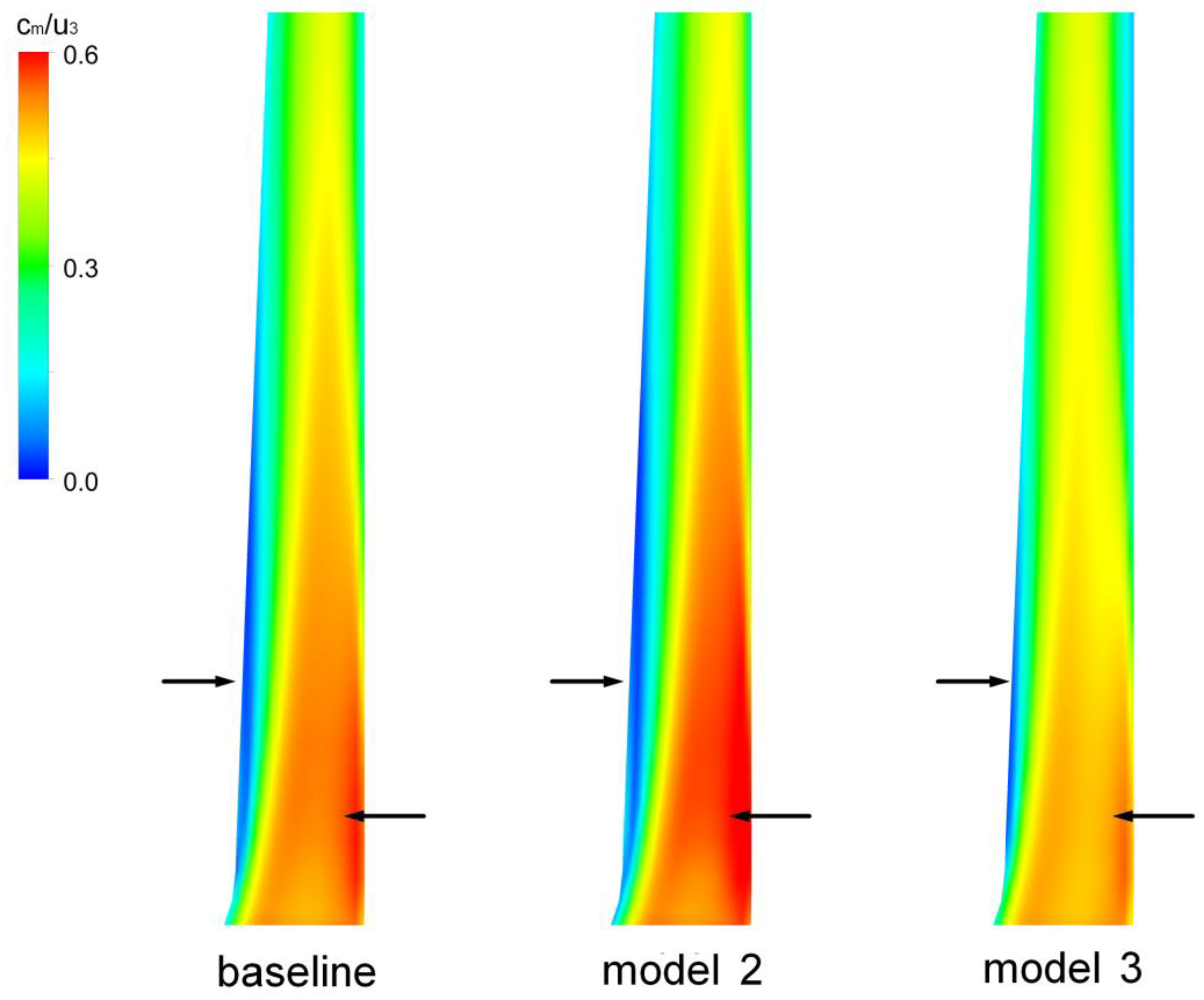
The distribution of absolute airflow angles at the inlet of the vaneless diffuser is shown in Figure 16. Model 3 demonstrated a more uniform distribution in the circumferential direction. Model 2, however, demonstrated a decrease in airflow angle on the side of the wheel cover, while showing an increase on the side of the wheel. This resulted in a more pronounced gradient along the circumferential direction. The presence of a non-uniform flow at the vaneless diffuser inlet enhanced the probability of internal flow separation. Figure 17 illustrates the distribution of dimensionless meridional velocity (average circumferential mass) on the meridional surface of the vaneless diffuser. Model 2 experienced a wider range of flow separation on its wheel cover side, while also exhibiting a significant increase in meridional velocity on its wheel side. The consequence of this phenomenon was an amplified transverse velocity gradient within the vaneless diffuser, thereby exerting an influence on the efficiency. Model 3, in contrast, exhibited a reduction in flow separation on its wheel cover side, resulting in a more uniform distribution of transverse velocity.
4. Conclusions
In this study, the aerodynamic performance of a centrifugal compressor with leaned and bowed 3D blades was investigated. There was a significant change in isentropic efficiency of the modified models under design conditions. Specifically, models 1, 3, and 4 experienced an increase of 0.97%, 1.04%, and 0.79%, respectively, while model 2 experienced a decrease of 0.70%. The findings obtained by this study can be summarized as follows:
- (a)
- The leaned and bowed 3D blades primarily modified the spanwise curvature of the blade. When a spanwise section profile was rotated at a certain angle along the rotating axis of the impeller, the curvature along the spanwise direction of the leading edge changed little due to the large spanwise height of the blade. As a result, there was a negligible influence on the upstream flow. On the contrary, the spanwise height of the trailing edge of the blade was smaller, resulting in a relatively greater structural variation at the trailing edge. As a consequence, the flow both downstream and at the outlet of the blade channel was significantly influenced.
- (b)
- Due to the inclination of the blade tip towards the suction surface side and the deviation of the 50% spanwise section profile towards the suction surface side, the blade was concave towards the pressure surface side, the flow was gradually lifted from the blade root to the blade tip in the downstream to outlet area of the flow channel. The load on the trailing edge of the blade was reduced, and the flow was more closely aligned with the blade. The flow separation was reduced, and the outlet velocity of the impeller was more evenly distributed along the spanwise direction. At the same time, the larger radial velocity gradient near the blade tip area suppressed the backflow on the shroud side, which made the flow at the impeller outlet more stable.
- (c)
- The improvement in impeller outlet flow made the inlet flow of the diffuser more stable, the flow separation on the shroud side decreased, and the spanwise velocity distribution was more uniform, resulting in higher diffusion efficiency.
The current research in this article was based on numerical simulation results. In the future, the reliability of the simulation method and modification method will be verified through experiments. At the same time, thermodynamic discussions will be added to further analyze the results in order to better explain the mechanism of compressor performance improvement.
Author Contributions
Y.Z. and Z.L. conceived and wrote the paper; Z.L., W.K. and G.S. analyzed the data; F.Z., C.Z. and F.K. contributed the reagents/materials/analysis tools. All authors have read and agreed to the published version of the manuscript.
Funding
This research was supported by the Zhejiang Provincial Natural Science Foundation of China under Grant No. LTGY24E060001.
Data Availability Statement
The data presented in this study are available on request from the corresponding author. The data are not publicly available due to privacy.
Conflicts of Interest
Authors Wanmin Kong, Genqiang Shao, Fujian Zhu, Chaowei Zhang, and Feiyue Kong are employed by the company Zhejiang Mingzhen Electric&Electronic Co., Ltd.; the remaining authors declare that the research was conducted in the absence of any commercial or financial relationships that could be construed as a potential conflict of interest.
References
- Yue, W.; Huanhuan, B.; Jianqin, F.; Xun, W.; Jingping, L. Review of recent developments in fuel cell centrifugal air compressor: Comprehensive performance and testing techniques. Int. J. Hydrogen Energy 2023, 4, 262. [Google Scholar]
- Jĭrí, V.; Pavel, N. Identification of Aerodynamic Tonal Noise Sources of a Centrifugal Compressor of a Turbocharger for Large Stationary Engines. Appl. Sci. 2023, 13, 5964. [Google Scholar] [CrossRef]
- Zhehong, L.; Wenbin, C.; Xinxue, Y.; Yikun, W. Experimental Investigation on the Noise Characteristics of a Squirrel-Cage Fan with Different Blade Lengths. Energies 2023, 16, 69. [Google Scholar]
- Hergt, A.; Klinner, J.; Wellner, J.; Willert, C.; Beversdorff, M. The present challenge of transonic compressor blade design. J. Turbomach. 2019, 141, 4043329. [Google Scholar] [CrossRef]
- Rosic, B.; Xu, L. Blade Lean and Shroud Leakage Flows in Low Aspect Ratio Turbines. In Proceedings of the ASME Turbo Expo 2008: Power for Land, Sea, and Air, Berlin, Germany, 9–13 June 2012. [Google Scholar]
- Arkadiusz, B.; Kirill, K.; Robert, J.; Rafał, B. Numerical Study on Sensitivity of Turbofan Engine Performance to Blade Count of Centrifugal Compressor Impeller. Energies 2023, 16, 5251. [Google Scholar] [CrossRef]
- Huanxin, Z.; Lei, T.; Dangguo, Y.; Bing, L.; Honggang, F.; Hongshuai, L. Optimization Design and Pressure Fluctuation Suppression Based on Orthogonal Method for a Centrifugal Compressor. Machines 2023, 11, 559. [Google Scholar] [CrossRef]
- Oyama, A.; Liou, M.S.; Obayashi, S. High-fidelity swept and leaned rotor blade design optimization using evolutionary algorithm. In Proceedings of the 16th AIAA Computational Fluid Dynamics Conference, Orlando, FL, USA, 23–26 June 2003; p. 4091. [Google Scholar]
- Hiradate, K.; Kobayashi, H.; Sugimura, K.; Ito, T.; Nishida, H. Proposal and experimental verification of design guidelines for centrifugal compressor impellers with curvilinear element blades to improve compressor performance. J. Turbomach. 2015, 137, 051008. [Google Scholar] [CrossRef]
- Hiradate, K.; Kobayashi, H.; Nishioka, T. Investigation on effect of curvilinear element blades on centrifugal impeller performance. In Proceedings of the ASME Turbo Expo, Charlotte, NC, USA, 26–30 June 2017; p. 63213. [Google Scholar]
- Yang, L.; Jiatong, L.; Xiangli, L.; Zhehong, L.; Guohui, L.; Lixing, Z. Large eddy simulation of particle hydrodynamic characteristics in a dense gas-particle bubbling fluidized bed. Powder Technol. 2024, 433, 119285. [Google Scholar]
- Li, Z.; Luo, P.; Zhu, M. Effect of Motor Installation Heights on the Performance of an Isolated Centrifugal Fan. Processes 2023, 11, 2116. [Google Scholar] [CrossRef]
- Li, Z.; Ye, X.; Wei, Y. Investigation on Vortex Characteristics of a Multi-Blade Centrifugal Fan near Volute Outlet Region. Processes 2020, 8, 1240. [Google Scholar] [CrossRef]
- Li, Z.; Dou, H.; Lin, P. Design for a Squirrel Cage Fan with Double Arc Blade. J. Appl. Fluid Mech. 2020, 13, 881–891. [Google Scholar] [CrossRef]
- Li, Z.; Luo, P.; Zhu, M.; Liu, Y.; Chen, Z. Surrogate model on the extension operation range of an isolated centrifugal fan. J. Appl. Fluid Mech. 2024, 17, 900–911. [Google Scholar]
- Xu, C.; Amano, R. Aerodynamic and structure considerations in centrifugal compressor design blade lean effects. In Proceedings of the ASME Turbo Expo, Copenhagen, Denmark, 11–15 June 2012; p. 68207. [Google Scholar]
- Sugimura, K.; Kobayashi, H.; Nishida, H. Design optimization and experimental verification of centrifugal compressors with curvilinear element blades. In Proceedings of the ASME Turbo Expo, Copenhagen, Denmark, 11–15 June 2012; p. 69162. [Google Scholar]
- Shuhao, W.; Donghai, J.; Yin, Z.; Kun, W.; Xingmin, G. A forward-curved blade centrifugal compressor for anode recirculation in proton exchange membrane fuel cells. Int. J. Hydrogen Energy 2024, 53, 736–748. [Google Scholar]
- Ertang, L.; Yingxue, Y. Blade design and analysis of centrifugal compressors for the transcritical carbon dioxide refrigeration cycle. Case Stud. Therm. Eng. 2023, 45, 102884. [Google Scholar]
- Tsukamoto, K.; Hiradate, K.; Sakamoto, K.; Chiba, H.; Shinkawa, Y. Efficiency increase in centrifugal compressor with open impeller by using curvilinear element blade. In Proceedings of the ASME Turbo Expo, Montreal, QC, Canada, 15–19 June 2015; p. 43193. [Google Scholar]
- Zhenfang, F.; Hongkun, L.; Hongwei, C.; Jiannan, D. Research on Running Status Monitoring and Rotating Blade Crack Detection of Large-Scale Centrifugal Compressor Based on Blade Tip Timing Technique. IEEE Trans. Instrum. Meas. 2023, 72, 3501011. [Google Scholar]
- Jang, C.M.; Abudus, S.; Kim, K.Y. Optimal design of swept, leaned and skewed blades in a transonic axial compressor. In Proceedings of the ASME Turbo Expo, Barcelona, Spain, 8–11 May 2006; p. 90384. [Google Scholar]
- Oh, J.S.; Buckley, C.W.; Agrawal, G.L. Numerical study on the effects of blade lean on high-pressure centrifugal impeller performance. In Proceedings of the ASME Turbo Expo, Vancouver, BC, Canada, 6–10 June 2011; p. 45383. [Google Scholar]
- Eisenlohr, G.; Hartmut, K.; Franz, A.R.; Valentin, T. Investigation of the flow through a high pressure ratio centrifugal impeller. In Proceedings of the ASME Turbo Expo, Amsterdam, The Netherlands, 3–6 June 2002; p. 30394. [Google Scholar]
- Luca, M.; Ernesto, C.; Sebastiano, M. Assessment of various turbulence models in a high pressure ratio centrifugal compressor with an object oriented CFD code. In Proceedings of the ASME Turbo Expo, Charlotte, NC, USA, 26–30 June 2017; p. 63213. [Google Scholar]
Figure 1.
Schematic of the compressor and computational domain: (a) schematic of the impeller, (b) meridional plane schematic of the computational domain.
Figure 1.
Schematic of the compressor and computational domain: (a) schematic of the impeller, (b) meridional plane schematic of the computational domain.

Figure 2.
Structural grid of the centrifugal compressor: (a) single-passage structural cells, (b) y+ contour of the blade, (c) mesh details at the leading edge of the blade, (d) mesh details at the trailing edge of the blade.
Figure 2.
Structural grid of the centrifugal compressor: (a) single-passage structural cells, (b) y+ contour of the blade, (c) mesh details at the leading edge of the blade, (d) mesh details at the trailing edge of the blade.

Figure 3.
Grid independence validation.

Figure 4.
Comparison between numerical simulation and experimental results: (a) pressure coefficient—mass flow rate, (b) total pressure efficiency—mass flow rate.
Figure 4.
Comparison between numerical simulation and experimental results: (a) pressure coefficient—mass flow rate, (b) total pressure efficiency—mass flow rate.

Figure 5.
Comparison of impeller inlet Mach numbers under the design condition (Q = 2.55 kg/s).

Figure 6.
Comparison of impeller outlet Mach numbers under the design condition (Q = 2.55 kg/s).

Figure 7.
Comparison of impeller geometry differences: (a) cross sections of blade along the spanwise direction, (b) impeller geometries.
Figure 7.
Comparison of impeller geometry differences: (a) cross sections of blade along the spanwise direction, (b) impeller geometries.

Figure 8.
Performance comparison: (a) total pressure ratio—mass flow rate, (b) isentropic efficiency—mass flow rate.
Figure 8.
Performance comparison: (a) total pressure ratio—mass flow rate, (b) isentropic efficiency—mass flow rate.

Figure 9.
Meridional velocity distribution downstream of impeller passages.

Figure 10.
Relative velocity distribution on the suction surface side of the main blade at 95% spans.
Figure 10.
Relative velocity distribution on the suction surface side of the main blade at 95% spans.

Figure 11.
Pressure distribution and difference between the suction surface and pressure surface of the main blade at two spans: (a) pressure distribution at 50% spans, (b) pressure distribution at 95% spans.
Figure 11.
Pressure distribution and difference between the suction surface and pressure surface of the main blade at two spans: (a) pressure distribution at 50% spans, (b) pressure distribution at 95% spans.

Figure 12.
Entropy distribution at 95% spans.

Figure 13.
Radial velocity distribution at impeller outlet along spanwise direction.

Figure 14.
Radial velocity distribution along circumferential direction of 50% span at impeller outlet.
Figure 14.
Radial velocity distribution along circumferential direction of 50% span at impeller outlet.

Figure 15.
Blade angle and relative flow angle distribution and difference: (a) blade angle and relative flow angle distribution of the baseline along the streamwise location, (b) difference between blade angle and relative flow angle for the three models at different spans (the dashed line is the zero scale line).

Figure 16.
Absolute flow angle distribution at inlet of vaneless diffuser.

Figure 17.
Meridional velocity distribution on meridional surface of vaneless diffuser.


| Parameters of the Original Centrifugal Compressor | Sizes |
|---|---|
| Inlet total pressure (Pa) | 101,325 |
| Inlet total temperature (K) | 288.15 |
| Shaft speed (rpm) | 50,000 |
| Blade count full/splitter (rpm) | 13/13 |
| Design mass flow rate (kg/s) | 2.55 |
| Blade angle of leading edge tip (deg) | 26.5 |
| Impeller tip radius (mm) | 112 |
| Blade angle of trailing edge (deg) | 52 |
| Impeller pressure ratio (under design mass flow rate) | 6.1 |
| Efficiency (under design mass flow rate) | 0.84 |
Table 2.
Grid parameters of the compressor.
| Grid | ||
|---|---|---|
| No. | Total Pressure Ratio | Number of Cells |
| 1 | 6.453 | 0.77 × 10⁶ |
| 2 | 6.471 | 1.17 × 10⁶ |
| 3 | 6.477 | 1.67 × 10⁶ |
| 4 | 6.478 | 2.46 × 10⁶ |
Disclaimer/Publisher’s Note: The statements, opinions and data contained in all publications are solely those of the individual author(s) and contributor(s) and not of MDPI and/or the editor(s). MDPI and/or the editor(s) disclaim responsibility for any injury to people or property resulting from any ideas, methods, instructions or products referred to in the content. |
© 2024 by the authors. Licensee MDPI, Basel, Switzerland. This article is an open access article distributed under the terms and conditions of the Creative Commons Attribution (CC BY) license (https://creativecommons.org/licenses/by/4.0/).
Share and Cite
MDPI and ACS Style
Li, Z.; Kong, W.; Shao, G.; Zhu, F.; Zhang, C.; Kong, F.; Zhang, Y. Investigation on Aerodynamic Performance of a Centrifugal Compressor with Leaned and Bowed 3D Blades. Processes 2024, 12, 875. https://doi.org/10.3390/pr12050875
AMA Style
Li Z, Kong W, Shao G, Zhu F, Zhang C, Kong F, Zhang Y. Investigation on Aerodynamic Performance of a Centrifugal Compressor with Leaned and Bowed 3D Blades. Processes. 2024; 12(5):875. https://doi.org/10.3390/pr12050875
Chicago/Turabian StyleLi, Zhehong, Wanmin Kong, Genqiang Shao, Fujian Zhu, Chaowei Zhang, Feiyue Kong, and Yifan Zhang. 2024. "Investigation on Aerodynamic Performance of a Centrifugal Compressor with Leaned and Bowed 3D Blades" Processes 12, no. 5: 875. https://doi.org/10.3390/pr12050875
Note that from the first issue of 2016, this journal uses article numbers instead of page numbers. See further details here.