
Study on Hydrogen Direct Injection in RNG Combustion under Various Ignition Timings for Power Generation in a Retrofitted Gas Engine
 , ,
, ,
Abstract
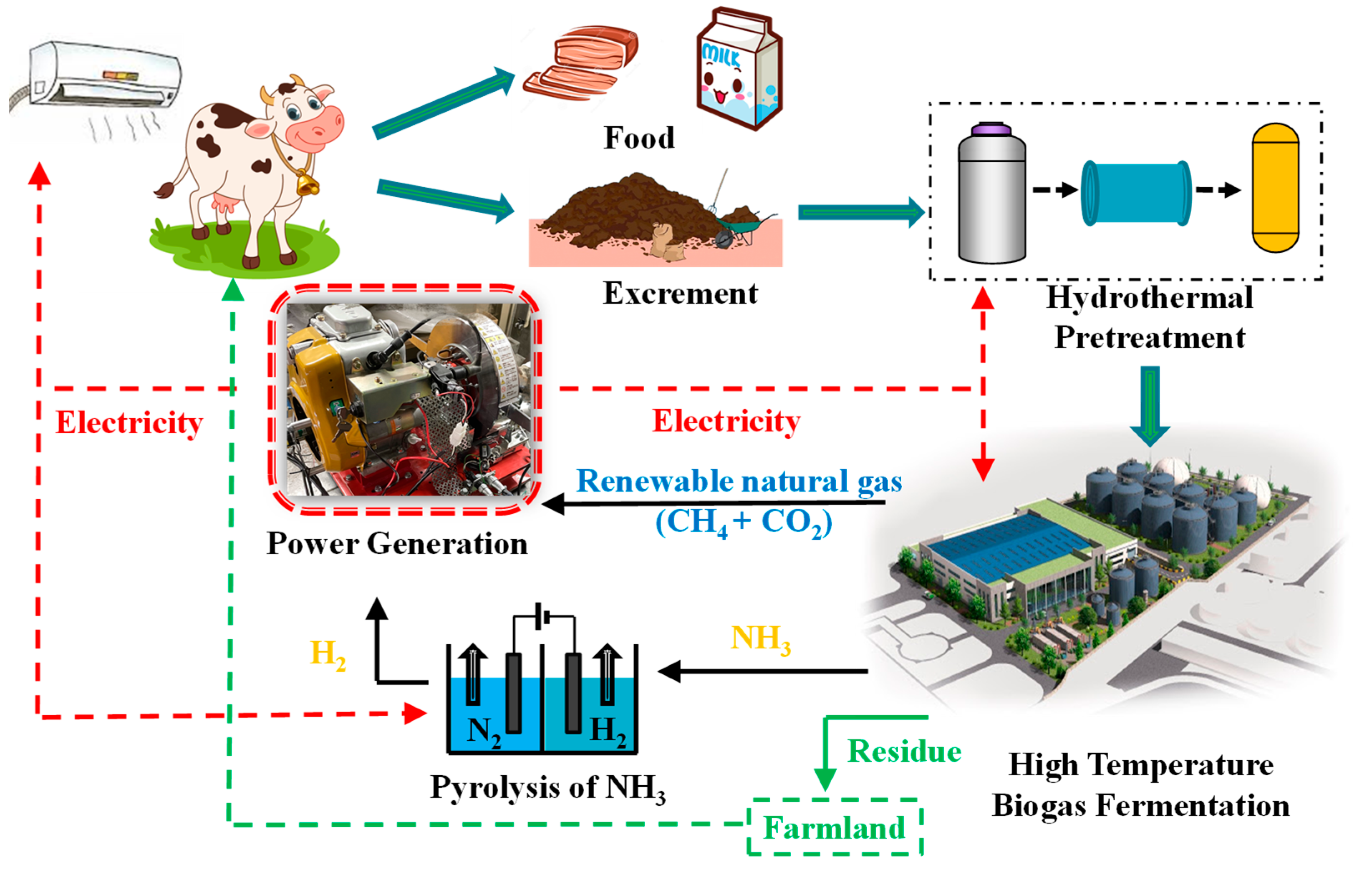
:1. Background
2. Introduction
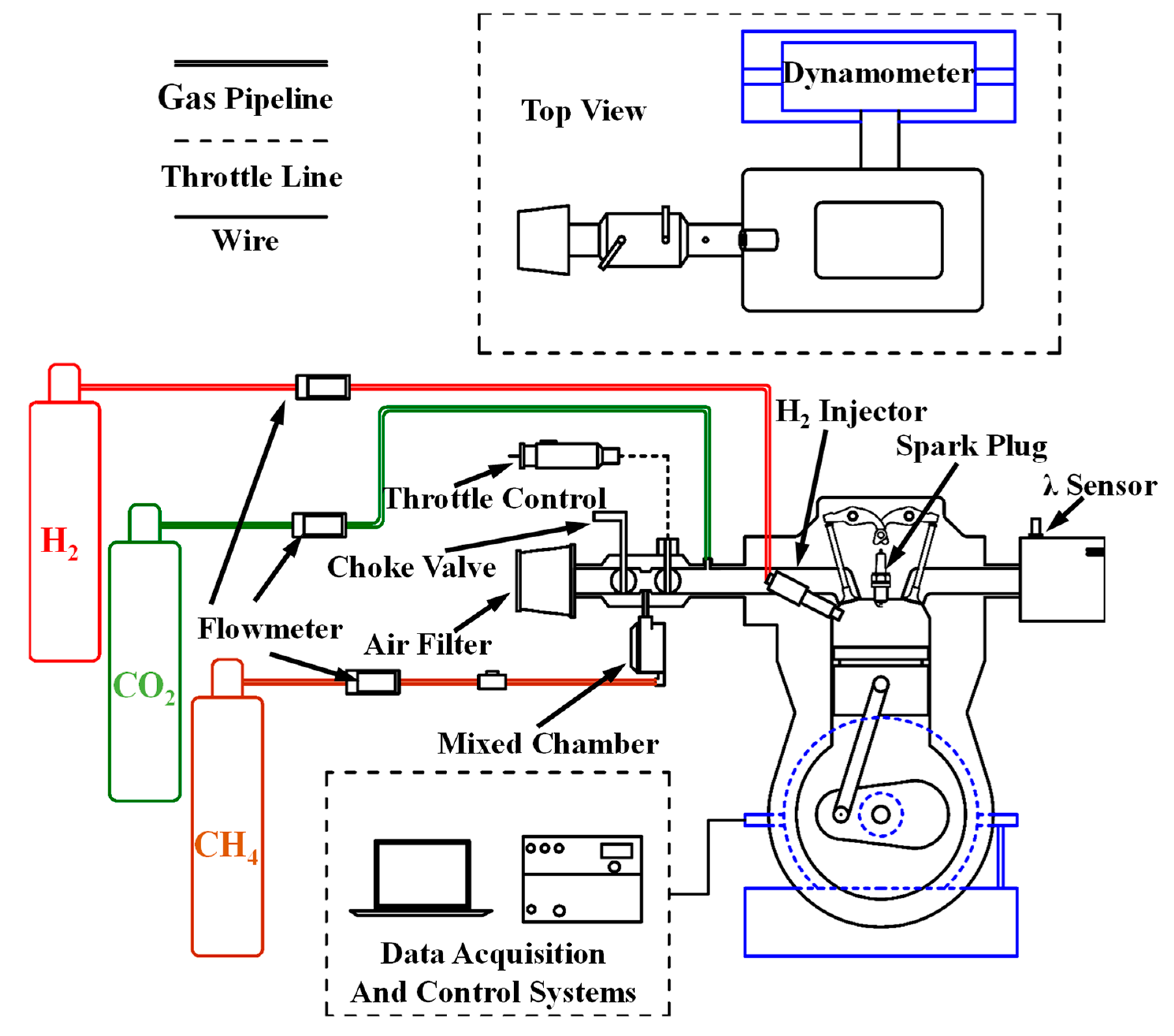
3. Experimental Conditions and Setup
4. Method of Calculation
5. Results and Discussion
6. Conclusions
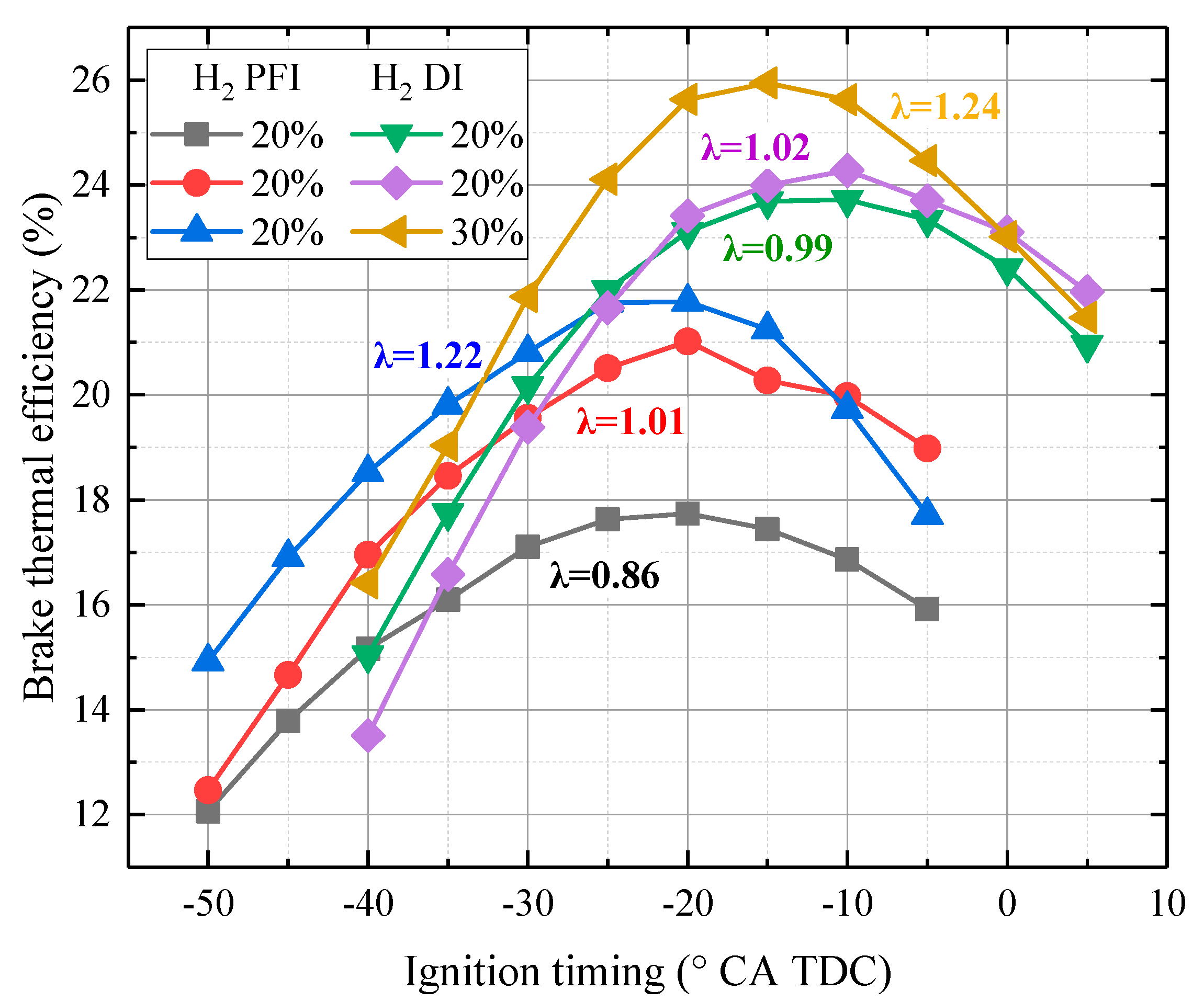
- (1)
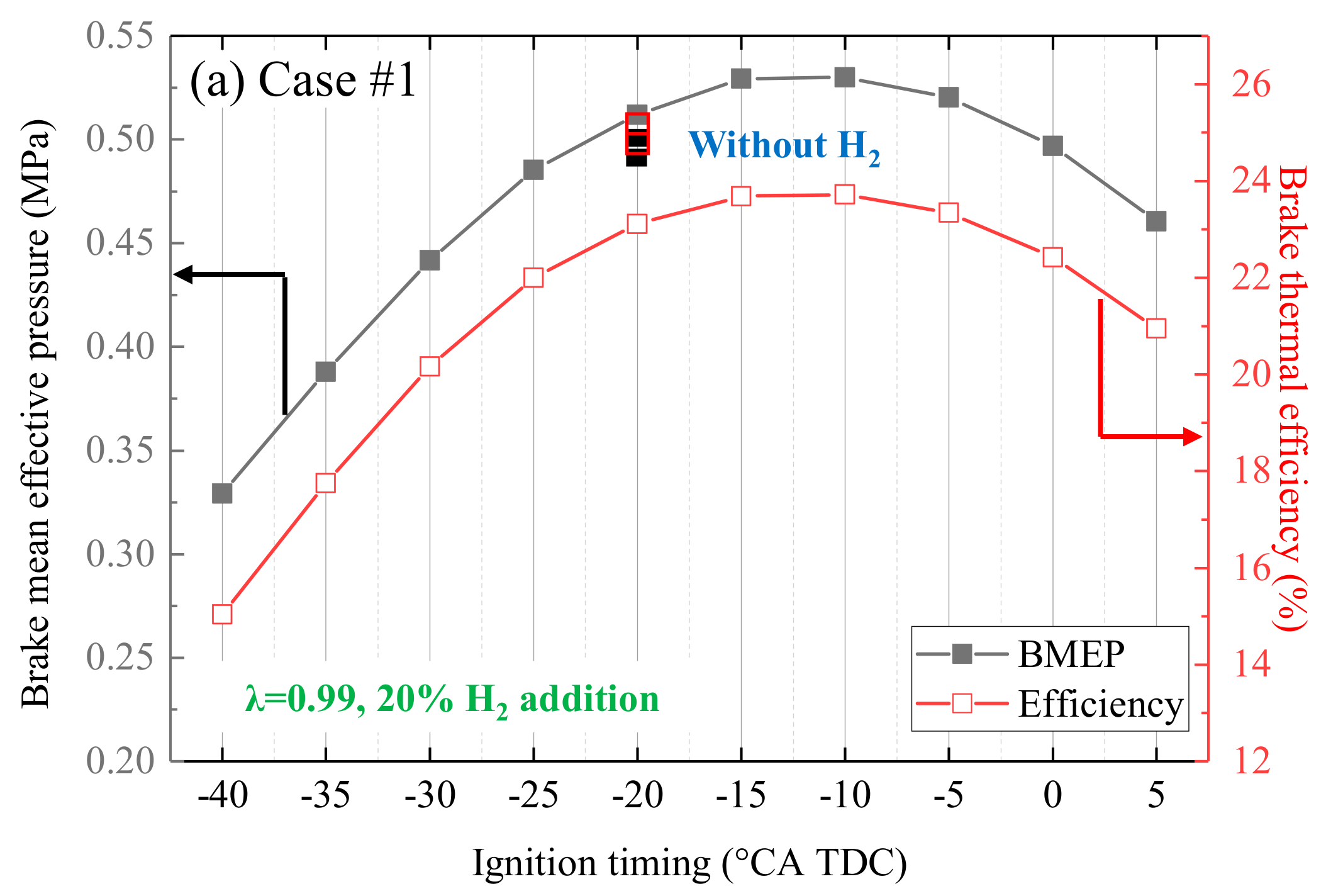
- In contrast to PFI, H2 DI injection could increase efficiency by 4% in this small engine. Additionally, H2 DI could retard the MBT ignition timing at 5 °CA.
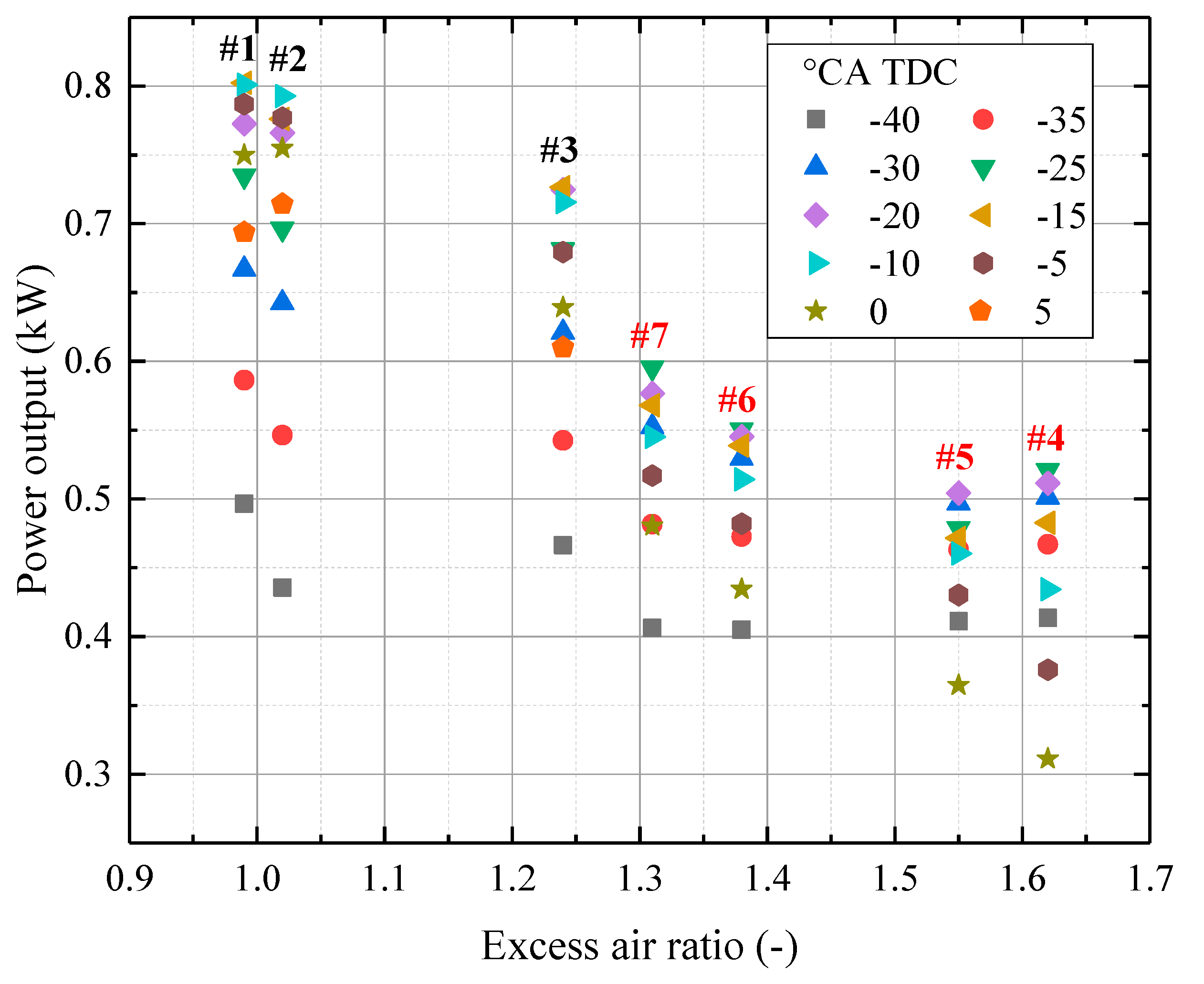
- (2)
- Larger λ shortens the variation in power output because H2 favors lean combustion, leading to stable combustion with different ignition timings. Moreover, power output becomes less sensitive to the ignition timing effect with more H2 enrichment.
- (3)
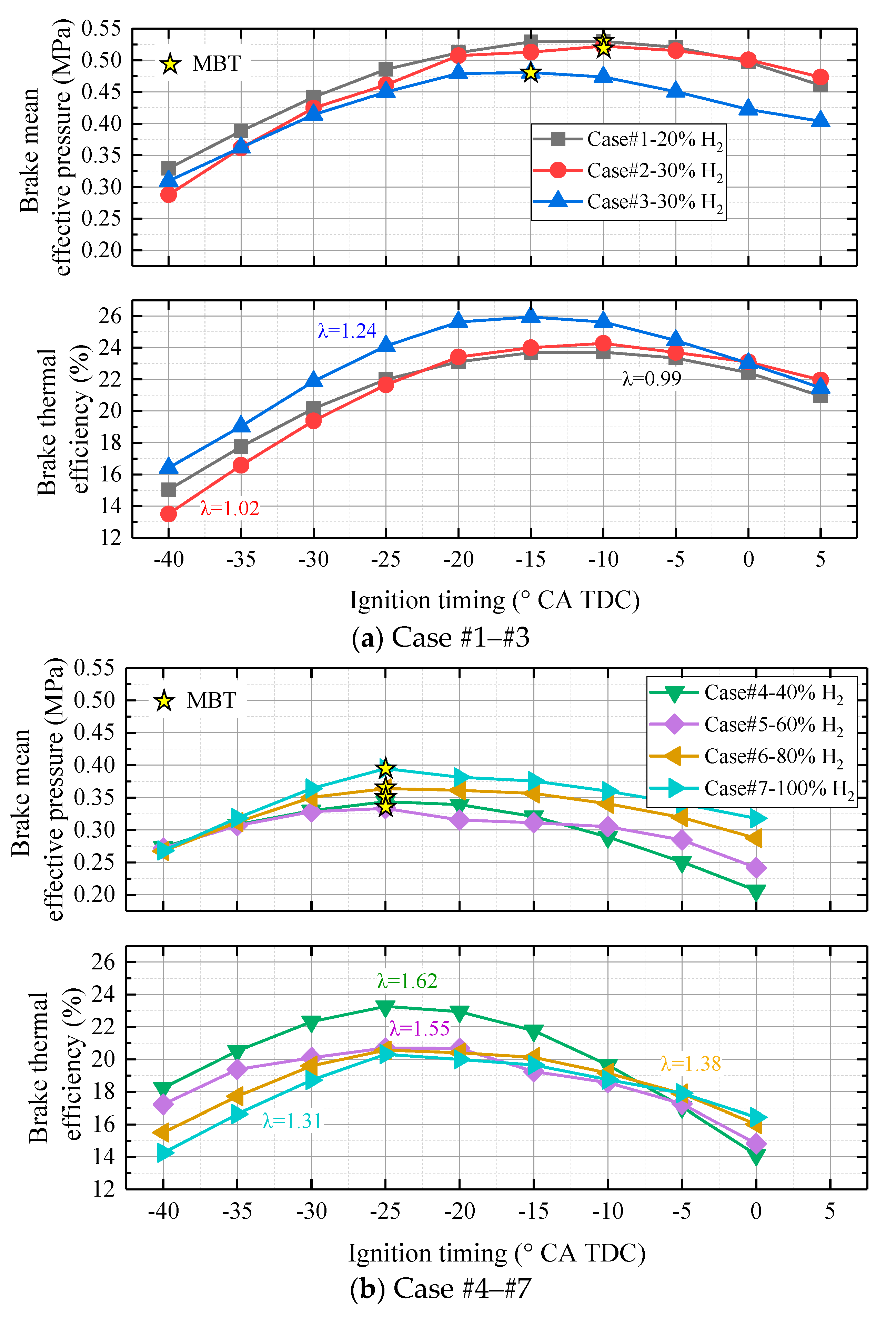
- In contrast to CH4/CH4 + CO2 combustion, under stoichiometric combustion, the BMEP increases with H2 addition but BTE decreases significantly. However, by enlarging λ to 1.24, both the BMEP and BTE increase significantly with H2 addition.
- (4)
- When λ < 1.3, the MBT ignition timing should be advanced from -10 to 15 °CA TDC. However, the MBT ignition timing is fixed at −25 °CA TDC when λ is larger than 1.3.
- (5)
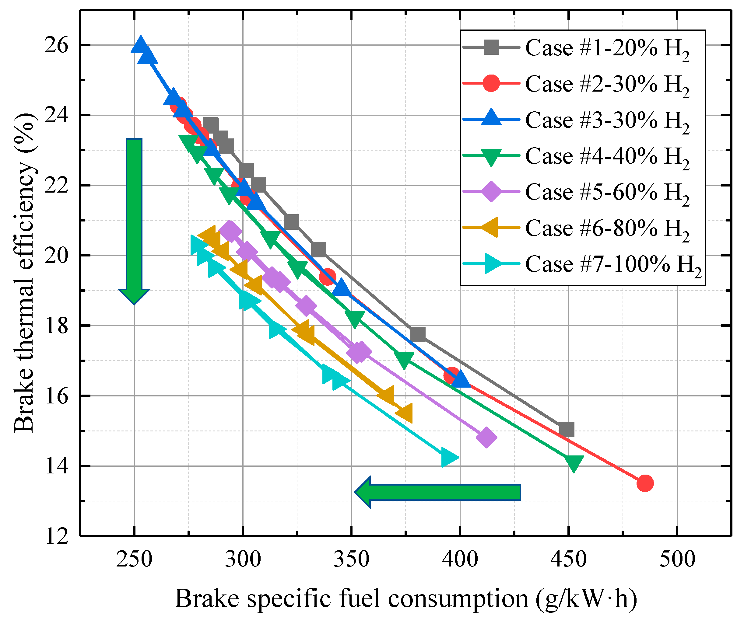
- There is a threshold at which H2 addition could not further increase the efficiency at lean-burn combustion. When the H2 fraction is smaller than 40%, the BTE increases with H2 addition. However, when the H2 fraction is larger than 40%, the BTE decreases.
- (6)
- If efficiency is the priority, 30% H2 addition with λ at 1.24 (−15 °CA TDC) should be selected. If higher the BMEP is preferred, 20% H2 addition with λ at 0.99 (−10 °CA TDC) should be selected.
- (7)
- With more H2 addition, both efficiency and BSFC decrease. And 30% H2 addition with λ at 1.24 is the best option when considering economy and efficiency.
Author Contributions
Funding
Data Availability Statement
Conflicts of Interest
References
- Mallapaty, S. How China could be carbon neutral by mid-century. Nature 2020, 586, 482–484. [Google Scholar] [CrossRef] [PubMed]
- Rosa, L.; Sanchez, D.L.; Mazzotti, M. Assessment of carbon dioxide removal potential via BECCS in a carbon-neutral Europe. Energy Environ. Sci. 2021, 14, 3086–3097. [Google Scholar] [CrossRef]
- Williams, J.H.; Jones, R.A.; Haley, B.; Kwok, G.; Hargreaves, J.; Farbes, J.; Torn, M.S. Carbon-neutral pathways for the United States. AGU Adv. 2021, 2, e2020AV000284. [Google Scholar] [CrossRef]
- Muradov, N.Z.; Veziroğlu, T.N. “Green” path from fossil-based to hydrogen economy: An overview of carbon-neutral technologies. Int. J. Hydrog. Energy 2008, 33, 6804–6839. [Google Scholar] [CrossRef]
- Huovila, A.; Siikavirta, H.; Rozado, C.A.; Rökman, J.; Tuominen, P.; Paiho, S.; Hedman, A.; Ylén, P. Carbon-neutral cities: Critical review of theory and practice. J. Clean. Prod. 2022, 41, 130912. [Google Scholar] [CrossRef]
- Parker, N.; Williams, R.; Dominguez-Faus, R.; Scheitrum, D. Renewable natural gas in California: An assessment of the technical and economic potential. Energy Policy 2017, 111, 235–245. [Google Scholar] [CrossRef]
- Kieffer, M.; Brown, T.; Brown, R.C. Flex fuel polygeneration: Integrating renewable natural gas into Fischer-Tropsch synthesis. Appl. Energy 2016, 170, 208–218. [Google Scholar] [CrossRef]
- Thamsiriroj, T.; Smyth, H.; Murphy, J.D. A roadmap for the introduction of gaseous transport fuel: A case study for renewable natural gas in Ireland. Renew. Sustain. Energy Rev. 2011, 15, 4642–4651. [Google Scholar] [CrossRef]
- Skorek-Osikowska, A.; Martín-Gamboac, M.; Dufour, J. Thermodynamic, economic and environmental assessment of renewable natural gas production systems. Energy Convers. Manag. X 2020, 7, 100046. [Google Scholar] [CrossRef]
- Kotagodahetti, R.; Hewage, K.; Razi, F.; Sadiq, R. Comparative life cycle environmental and cost assessments of renewable natural gas production pathways. Energy Convers. Manag. 2023, 278, 116715. [Google Scholar] [CrossRef]
- Zhou, J.; Chen, L.; Zhang, R.; Zhao, W. Study on Oxidation Activity of Hydrogenated Biodiesel–Ethanol–Diesel Blends. Processes 2024, 12, 462. [Google Scholar] [CrossRef]
- Cheng, L.; Chen, Y.; Pei, Y.; Sun, G.; Zou, J.; Peng, S.; Zhang, Y. NO and CO Emission Characteristics of Laminar and Turbulent Counterflow Premixed Hydrogen-Rich Syngas/Air Flames. Processes 2024, 12, 475. [Google Scholar] [CrossRef]
- Sahoo, S.; Srivastava Dhananjay, K. Effect of compression ratio on engine knock, performance, combustion and emission characteristics of a bifuel CNG engine. Energy 2021, 38, 121144. [Google Scholar] [CrossRef]
- Hao, D.; Mehra Roopesh, K.; Luo, S.; Nie, Z.; Ren, X.; Ma, F. Experimental study of hydrogen enriched compressed natural gas (HCNG) engine and application of support vector machine (SVM) on prediction of engine performance at specific condition. Int. J. Hydrog. Energy 2020, 45, 5309–5325. [Google Scholar] [CrossRef]
- Merrin, Z.; Francisco Paul, W. Unburned methane emissions from residential natural gas appliances. Environ. Sci. Technol. 2019, 53, 5473–5482. [Google Scholar] [CrossRef] [PubMed]
- Luo, S.; Ma, F.; Mehra Roopesh, K.; Huang, Z. Deep insights of HCNG engine research in China. Fuel 2020, 263, 116612. [Google Scholar] [CrossRef]
- Bayramoglu, K.; Yılmaz, S. Emission and performance estimation in hydrogen injection strategies on diesel engines. Int. J. Hydrog. Energy 2020, 46, 29732–29744. [Google Scholar] [CrossRef]
- Navarro, E.; Leo Teresa, J.; Corral, R. CO2 emissions from a spark ignition engine operating on natural gasehydrogen blends (HCNG). Appl. Energy 2013, 101, 112–120. [Google Scholar] [CrossRef]
- Ma, F.; Wang, Y.; Liu, H.; Li, Y.; Wang, J.; Zhao, S. Experimental study on thermal efficiency and emission characteristics of a lean-burn hydrogen enriched natural gas engine. Int. J. Hydrog. Energy 2007, 32, 5067–5075. [Google Scholar] [CrossRef]
- Lim, G.; Lee, S.; Park, C.; Choi, Y.; Kim, C. Effects of compression ratio on performance and emission characteristics of heavy-duty SI engine fuelled with HCNG. Int. J. Hydrog. Energy 2013, 38, 4831–4838. [Google Scholar] [CrossRef]
- Hu, E.; Huang, Z.; Liu, B.; Zheng, J.; Gu, X.; Huang, B. Experimental investigation on performance and emissions of a spark-ignition engine fuelled with natural gas–hydrogen blends combined with EGR. Int. J. Hydrog. Energy 2009, 34, 528–539. [Google Scholar] [CrossRef]
- Luo, H.; Chang, F.; Jin, Y.; Ogata, Y.; Matsumura, Y.; Ichikawa, T.; Nishida, K.; Kim, W.; Nakashimada, Y. Experimental investigation on performance of hydrogen additions in natural gas combustion combined with CO2. Int. J. Hydrog. Energy 2021, 46, 34958–34969. [Google Scholar] [CrossRef]
- Jin, Y.; Luo, H.; Zhang, G.; Zhai, C.; Ogata, Y.; Matsumura, Y.; Ichikawa, T.; Nishida, K.; Nakashimada, Y.; Kim, W. Ignition timing effect on the combustion performance of hydrogen addition in methane fermentation gas in a local energy system. Fuel 2022, 324, 124714. [Google Scholar] [CrossRef]
- Wimmer, A.; Wallner, T.; Ringler, J.; Gerbig, F. H2-Direct Injection—A Highly Promising Combustion Concept; SAE Technical Paper No. 2005-01-0108; SAE: Warrendale, PA, USA, 2005. [Google Scholar] [CrossRef]
- Mohammadi, A.; Shioji, M.; Nakai, Y.; Ishikura, W.; Tabo, E. Performance and combustion characteristics of a direct injection SI hydrogen engine. Int. J. Hydrog. Energy 2007, 32, 296–304. [Google Scholar] [CrossRef]
- Wallner, T.; Nande, A.M.; Naber, J. Evaluation of Injector Location and Nozzle Design in a Direct-Injection Hydrogen Research Engine; SAE Technical Paper No. 2008-01-1785; SAE: Warrendale, PA, USA, 2008. [Google Scholar] [CrossRef]
- Mithun, K.R.; Nobuyuki, K.; Eiji, T.; Takashi, F.R. High-pressure hydrogen jet and combustion characteristics in a direct-injection hydrogen engine. SAE Int. J. Fuels Lubr. 2012, 5, 1414–1425. Available online: https://www.jstor.org/stable/26272855 (accessed on 10 March 2024).
- Li, X.Y.; Sun, B.G.; Zhang, D.S.; Wang, X.; Bao, L.Z.; Luo, Q.H. Experimental study on the cycle variation characteristics of direct injection hydrogen engine. Energy Convers. Manag. X 2022, 15, 100260. [Google Scholar] [CrossRef]
- Klepatz, K.; Rottengruber, H.; Zeilinga, S.; Koch, D.; Prümm, W. Loss Analysis of a Direct-Injection Hydrogen Combustion Engine; SAE Technical Paper No. 2018-01-1686; SAE: Warrendale, PA, USA, 2018. [Google Scholar] [CrossRef]
- Di Iorio, S.; Sementa, P.; Vaglieco, B.M. Analysis of combustion of methane and hydrogen–methane blends in small DI SI (direct injection spark ignition) engine using advanced diagnostics. Energy 2016, 108, 99–107. [Google Scholar] [CrossRef]
- Hagos, F.Y.; Aziz AR, A.; Sulaiman, S.A.; Mamat, R. Engine speed and air-fuel ratio effect on the combustion of methane augmented hydrogen rich syngas in DI SI engine. Int. J. Hydrog. Energy 2019, 44, 477–486. [Google Scholar] [CrossRef]
- Sementa, P.; de Vargas Antolini, J.B.; Tornatore, C.; Catapano, F.; Vaglieco, B.M.; Sánchez, J.J.L. Exploring the potentials of lean-burn hydrogen SI engine compared to methane operation. Int. J. Hydrog. Energy 2022, 47, 25044–25056. [Google Scholar] [CrossRef]
- Luo, H.; Jin, Y.; An, Y.; Matsumura, Y.; Ichikawa, T.; Kim, W.; Nishida, K.; Nakashimada, Y. Combustion Performance of Methane Fermentation Gas with Hydrogen Addition under Various Ignition Timings; SAE Technical Paper No. 2022-32-0043; SAE: Warrendale, PA, USA, 2022. [Google Scholar] [CrossRef]


| Engine Type | Robin EH12-2DS |
|---|---|
| Compression ratio | 8.5 |
| Displacement volume | 121 cc |
| Engine speed | 1500 rpm |
| Bore and stroke | 60 mm & 43 mm |
| Connecting rod length | 73 mm |
| Ignition timing | −40, −35, −30, −25, −20, −15, −10, −5, 0, 5° CA TDC |
| Fuel | CH4 + CO2, 20%, 30%, 40%, 60%, 80%, 100% H2 |
| H2 injection pressure | 7 MPa |
| H2 injection timing | 0° Compression TDC (closed valve injection) |
| Throttle opening | 100% |
| Flowrate (L/min) [λ] | |||
|---|---|---|---|
| Case #1 | CH4 | CH4 + CO2 | 20% H2 |
| 5.0 [1.10] | 5.0 + 5.0 [1.10] | 5.0 + 5.0 + 2.0 [0.99] | |
| Case #2 | CH4 | CH4 + CO2 | 30% H2 |
| 4.6 [1.22] | 4.6 + 4.6 [1.22] | 4.6 + 4.6 + 2.8 [1.02] | |
| Case #3 | CH4 | CH4 + CO2 | 30% H2 |
| 4.0 [1.45] | 4.0 + 4.0 [1.45] | 4.0 + 4.0 + 2.4 [1.24] | |
| Case #4 | CH4 | CH4 + CO2 | 40% H2 |
| × | × | 3.0 + 3.0 + 2.4 [1.62] | |
| Case #5 | CH4 | CH4 + CO2 | 60% H2 |
| × | × | 3.0 + 3.0 + 3.6 [1.55] | |
| Case #6 | CH4 | CH4 + CO2 | 80% H2 |
| × | × | 3.0 + 3.0 + 4.8 [1.38] | |
| Case #7 | CH4 | CH4 + CO2 | 100% H2 |
| × | × | 3.0 + 3.0 + 6.0 [1.31] | |
| Properties | H2 | CH4 |
|---|---|---|
| Density (kg/m3) | 0.084 | 0.668 |
| Lower heating value (LHV) (J/kg) | 1.197 × 10⁸ | 4.672 × 10⁷ |
| Volumetric LHV (J/m3) | 1.022 × 10⁷ | 3.297 × 10⁷ |
| Stoichiometric air–fuel ratio | 34.32 | 17.16 |
| Laminar flame speed (m/s) | 2.65~3.25 | 0.38 |
| Minimum ignition energy (J) | 2.0 × 10⁻⁵ | 2.8 × 10⁻⁴ |
| Quenching distance in air (m) | 6.4 × 10⁻⁴ | 2.03 × 10⁻³ |
Disclaimer/Publisher’s Note: The statements, opinions and data contained in all publications are solely those of the individual author(s) and contributor(s) and not of MDPI and/or the editor(s). MDPI and/or the editor(s) disclaim responsibility for any injury to people or property resulting from any ideas, methods, instructions or products referred to in the content. |
© 2024 by the authors. Licensee MDPI, Basel, Switzerland. This article is an open access article distributed under the terms and conditions of the Creative Commons Attribution (CC BY) license (https://creativecommons.org/licenses/by/4.0/).
Share and Cite
Yu, M.; Luo, H.; Zhou, B.; Liu, Y.; Zhai, C.; Nishida, K.; Ge, J.-C. Study on Hydrogen Direct Injection in RNG Combustion under Various Ignition Timings for Power Generation in a Retrofitted Gas Engine. Processes 2024, 12, 585. https://doi.org/10.3390/pr12030585
Yu M, Luo H, Zhou B, Liu Y, Zhai C, Nishida K, Ge J-C. Study on Hydrogen Direct Injection in RNG Combustion under Various Ignition Timings for Power Generation in a Retrofitted Gas Engine. Processes. 2024; 12(3):585. https://doi.org/10.3390/pr12030585
Chicago/Turabian StyleYu, Meiqi, Hongliang Luo, Beini Zhou, Yang Liu, Chang Zhai, Keiya Nishida, and Jun-Cong Ge. 2024. "Study on Hydrogen Direct Injection in RNG Combustion under Various Ignition Timings for Power Generation in a Retrofitted Gas Engine" Processes 12, no. 3: 585. https://doi.org/10.3390/pr12030585