
Numerical Simulation of the Hydrogen-Based Directly Reduced Iron Melting Process
1
Steel Industry Green and Intelligent Manufacturing Technology Center, China Iron and Steel Research Institute Group, Beijing 100081, China
2
National Key Laboratory of Metallurgical Intelligent Manufacturing System, Beijing 100081, China
3
Metallurgical Technology Institute, Central Iron and Steel Research Institute, Beijing 100081, China
*
Author to whom correspondence should be addressed.
Processes 2024, 12(3), 537; https://doi.org/10.3390/pr12030537
Submission received: 19 January 2024
/
Revised: 20 February 2024
/
Accepted: 20 February 2024
/
Published: 8 March 2024
(This article belongs to the Special Issue Digital Research and Development of Materials and Processes)
Abstract
:In the context of carbon reduction and emission reduction, the new process of electric arc furnace (EAF) steelmaking based on direct hydrogen reduction is an important potential method for the green and sustainable development of the steel industry. Within an electric furnace for the hydrogen-based direct reduction of iron, after hydrogen-based directly reduced iron (HDRI) is produced through a shaft furnace, HDRI is melted or smelted in an EAF to form final products such as high-purity iron or high-end special steel. As smelting proceeds in the electric furnace, it is easy for pieces of HDRI to bond to each other and become larger pieces; they may even form an “iceberg”, and this phenomenon may then worsen the smelting working conditions. Therefore, the melting of HDRI is the key to affecting the smelting cycle and energy consumption of EAFs. In this study, based on the basic characteristics of HDRI, we established an HDRI melting model using COMSOL Multiphysics 6.0 and studied the HDRI melting process, utilizing pellets with a radius of 8 mm. The results of our simulation show that the HDRI melting process can be divided into three different stages: generating a solidified steel layer, melting the solidified steel layer, and melting HDRI bodies. Moreover, multiple HDRI processes are prone to bonding in the melting process. Increasing the spacing between pieces of HDRI and increasing the preheating temperature used on the HDRI can effectively reduce the aforementioned bonding phenomenon. When the melting pool temperature is 1873 K, increasing the spacing of HDRI to 10 mm and increasing the initial HDRI temperature to 973 K was shown to effectively reduce or eliminate the bonding phenomenon among pieces of HDRI. In addition, with the increase in the melting pool temperature, the time required for melting within the three stages of the HDRI melting process shortened, and the melting speed was accelerated. With the increase in the temperature used to preheat the HDRI, the duration of the solidified steel layer’s existence was also shortened, but this had no significant impact on the time required for the complete melting of HDRI. This study provides a theoretical basis for the optimization of the HDRI process within EAFs.
1. Introduction
Against the background of “carbon peak” and “carbon neutrality” in China, the traditional and long process of using a blast furnace converter in the steel industry is limited by many problems (such as limitations related to resources, energy, and the environment), and the carbon reduction potential of this process is also limited [1,2]. The electric arc furnace (EAF) steelmaking process has the advantages of a shorter duration, recyclable resources, and low energy consumption, and the amount of carbon emissions of per ton of steel is far lower than that of the aforementioned longer process [3,4,5,6]. At present, short-process EAF steelmaking involves scrap steel as its main raw material; this is an important aspect of manufacturing in the steel cycle. However, in the recycling process of scrap steel, there are problems such as uncontrollable mass composition and enrichment of impure elements [7], which will inevitably affect the quality of steel materials. The direct reduction of iron based on hydrogen reduction has the benefits of low carbon emissions, stable composition, and low contents of impurities; it produces high-quality raw materials for the subsequent production of high-quality steel. The new process of producing hydrogen-based directly reduced iron (HDRI) in an EAF will be important for the future production of high-quality steel.
Hydrogen-based directly reduced iron (HDRI) usually refers to iron formed as a consequence of the nonblast furnace ironmaking process of reducing iron ore via direct reduction within a gas-based shaft furnace that reacts with pure hydrogen by more than a 55% proportion. By 17 January 2024, the world’s first project to demonstrate this process had been independently developed and built by CISRI; it operated in Linyi City, Shandong Province, for 300 h, and the HDRI metalization rate reached more than 93%. HDRI can be used as a raw material for high-purity iron or high-end special steel; HDRI is melted or smelted in an electric furnace to form the final product. At present, many electric furnaces use directly reduced iron (DRI) and some scrap steel smelting [8]. In the smelting process that occurs within an electric furnace, the time taken to melt solid furnace material accounts for 60% of the total smelting cycle in the electric furnace; this aspect is what [8] most affects the smelting cycle and energy consumption of the electric furnace. When carrying out DRI or HDRI smelting, the formed pieces of material can easily bond with each other to become larger pieces and may even form an “iceberg”, thereby seriously adversely affecting the smelting conditions.
In the melting of solid materials in an electric furnace solid, researchers [9,10,11,12,13,14,15,16] have studied the melting mechanisms of scrap steel by changing the characteristics of the melting process (i.e., the temperature, shape, and composition of the melting pool); they did so by mixing in and adding scrap steel. Based on the method of finite difference, they established heat transfer and mass transfer equations, and described and verified both the melting mechanism and melting process. On this basis, a series of rapid melting technologies were developed for scrap steel. Most of these studies focused on studying the melting phenomenon of scrap steel within the iron and carbon melting pool, with the belief that the carburization stage is the key link to scrap steel melting. It is generally believed that the carbon content of molten iron is about 3~8%, and the carbon content of scrap steel is between 0.2% and 0.3%. But iron melt or carburization is often added to the scrap smelting process, so scrap-EAF process has high carbon content in this situation. Although both HDRI and scrap steel have similar carbon contents, the properties of HDRI and scrap steel are significantly different. Therefore, in this study, the use of scrap steel was not considered, and the melting phenomenon of HDRI is instead considered.
In the process of producing HDRI in an electric furnace, melting HDRI is the key to optimization. HDRI has different characteristics from scrap steel: (1) HDRI has a low carbon content, derived from the reducing gas; (2) HDRI is mostly formed into 10~16 mm solid-state balls, whose shapes and compositions are more uniform than those of scrap steel; (3) HDRI has a dense pore structure, with a large number of fine and uniform pores; (4) the density of the HDRI is relatively low; and (5) the melting point of HDRI is far lower than that of scrap steel and generally lower than the melting tank temperature; this means the melting process is mainly controlled by heat transfer. In the future, the carbon additions and emissions of the whole process will be greatly reduced. With this in mind, the influence of the carburizing process on the HDRI melting process is not critical.
At present, the production of HDRI reduced by pure hydrogen gas is minimal; however, DRI obtained via direct reduction of CO and hydrogen gas has already been utilized, and its basic characteristics are similar to those of HDRI. The melting of DRI in an EAF mainly relies on heating the arc of the liquid steel melting tank. The liquid steel melting tank is heated alongside stirring in the melting tank. When DRI is poorly melted, it is more likely to exhibit the “iceberg” phenomenon, which affects the smooth progress of electric furnace smelting; thus, the study of its melting phenomenon is very important. Many researchers have analyzed the characteristics of DRI smelting in industrial production. Cárdenas and others [17] analyzed the influence of DRI on EAF smelting based on material balance and energy balance. When the carbon content of DRI and the metallization rate are high, energy consumption decreases. However, with an increase in DRI gangue content, power consumption, and lime consumption, the amount of slag produced also increases. Kirschen et al. [18,19] analyzed the influence of different DRI ratios on electric furnace smelting and found that with an increase in the ratio of DRI added, the energy consumption of electric furnace increased. To further study the mechanism of change in DRI within the smelting process, Li and Sharifi [20,21] studied the reaction between DRI with high carbon content and slag, as well as the process of decarburization. When a DRI ball was immersed in liquid slag, the reaction between the high-carbon-content DRI and the slag caused an increase in the furnace pressure. Pfeiffer et al. [22] designed a thermal simulation device with which to study the interaction between DRI with different carbon contents and HBI (featuring a hot block) and high- and low-carbon contents. However, because of the short melting time of a single piece of DRI in the melting pool, changes in the melting process were not observed. Zhang et al. [23,24,25] established a numerical model for the melting of a single DRI particle in an Fe-C melting cell, believing that the DRI melting process is mainly controlled by heat transfer. The melting time was very short, and the authors analyzed the influence of the DRI radius and porosity on the melting time. At present, most studies in the literature focus on the macroscopic influence of the nature and amount of DRI added on electric furnace smelting [26,27,28,29]. Compared with the scrap melting process [30,31,32,33,34,35,36], there are few studies on low-carbon HDRI obtained via direct reduction of hydrogen or hydrogen-rich gas in the melting process of an EAF melting pool. That said, the process of melting HDRI is critical for direct reduction in an iron arc furnace. Therefore, reasonable methods are urgently needed so that we might study the process of melting HDRI and the bonding phenomenon involved in this process.
2. Model Description
2.1. Characteristics of HDRI
In this study, to reduce the bonding of HDRI and eliminate the “iceberg” phenomenon, HDRI was taken as the research object. Its chemical composition is shown in Table 1, and its microstructure is shown in Figure 1.
From Table 1, we can observe that the TFe of HDRI is as high as 92.42%, where FeO is only 6.60%, the metalization rate is 91.91%, and the carbon content is only 0.29%. From Figure 1, we can observe that there are numerous pore structures inside HDRI, with bright white regions indicating concentration of metallic Fe. According to its low carbon content and rich pore structure, a mathematical model of HDRI melting in a stable melting tank is established herein; the process of melting HDRI and its bonding phenomenon are described, and the melting characteristics of HDRI at different melting tank temperatures and different initial temperatures of HDRI are analyzed. This will provide a theoretical basis for the optimization of the parameters of hydrogen metallurgy electric furnaces.
2.2. Model Hypothesis
Modern EAF steelmaking adopts large steel retention technology to form a stable flat melting pool. HDRI is melted in liquid steel, and its main mechanism of heat transfer occurs between the arc and the liquid and the steel and HDRI via conduction [26,27]. Given the bonding phenomenon of HDRI in electric furnace smelting, its low carbon content, and its dense pore structure, a porous medium model was adopted to establish a mathematical model of HDRI melting in a stable melting pool. The melt pool was maintained at a stable high temperature. Therefore, in our study, heat transfer by radiation was deemed negligible in the process of melting HDRI in the EAF. The following assumptions were made.
- (1)
- Ignoring the reaction between HDRI and slag, HDRI falls directly into the molten cell for melting;
- (2)
- The heat transfer process is a controlled link within which the influence of carbon content is not considered;
- (3)
- Heat inside HDRI is transferred to a porous medium;
- (4)
- The temperature and properties of the molten steel pool in the unit are uniform and stable;
- (5)
- The liquid density and dynamic viscosity of the cell are regarded to be constant relative to the temperature.
2.3. Control Equation
In the case that most EAFs utilize smelting in a flat melting pool, considering the flow state is one of laminar flow, the inertial drag coefficient can be set to 0 at this time, and the convective acceleration and diffusion of the fluid can be ignored. The porous medium follows Darcy’s law, as shown as follows in Equation (3):
In the above formula,
is the mass source, which is the liquid phase produced by directly reduced iron melting, kg/(m3·s);
is the fluid phase saturation;
is the porosity, taken to be 0.4;
is the density of the directly reduced iron, kg/m3;
is the density of the molten pool steel fluid, kg/m3;
t is the time, s;
u is the seepage velocity, m/s;
is the seepage coefficient.
The liquid phase saturation is determined by the phase transition:
In the above formula,
is the initial liquid-phase saturation;
is the phase transition function.
The phase transition function, f, is defined as follows:
In the above formula,
is the melting point of the direct reduced iron, K;
W is taken to be 5 K, as determined by the phase transition temperature interval of the directly reduced iron.
According to energy conservation laws, the energy equation controlled by the heat transfer of the porous medium is as follows:
In the above formula,
is the specific heat capacity at a constant pressure, J/(kg·K);
t is the time, s;
u is the seepage velocity, m/s;
k is the thermal conductivity, W/(m·K);
Q is the heat source, W/(m3·s).
2.4. Model Parameter
This model was constructed using COMSOL Multiphysics 6.0 with the PARDISO solver, the principal perturbation was 1 × 10⁻¹³, the average grid mass was 0.89, and the physical parameters used in the calculation are shown in the table below (Table 2).
3. Results and Discussion
3.1. HDRI Melting and Its Heat Transfer Process
It was found that the HDRI melting process is controlled by mass transfer [26,27] only if the concentration gradient is steep or the temperature gradient is slight. In the low-carbon smelting process within a hydrogen reduction electric furnace, the temperature of the melting pool in the EAF is much higher than the HDRI melting point, and the carbon contents of the melting pool and HDRI are low. The influence of the carbon mass transfer process on the HDRI melting process can be ignored, and the heat transfer process is the critical element of HDRI melting. In a stable high-temperature melting cell, the heat transfer process of HDRI microsphere melting is regarded as an unsteady process with a typical free boundary. After the HDRI enters the molten tank, the boundary layer is formed due to the presence of a temperature gradient between the high-temperature liquid steel and the HDRI. The presence of the initial temperature boundary layer leads to the melting of the HDRI, and the heat transfer between the liquid steel and solid HDRI varies with the movement of the liquid steel–HDRI interface. The HDRI melting boundary is in a state of local thermal equilibrium, and the temperature change curve of the melting process is shown in the figure below (Figure 2). The initial temperature of the HDRI is T0, and the temperature of the liquid steel is Tm.
According to the above astatic heat transfer equation, the heat transfer in the liquid steel-HDRI thermal boundary layer can be expressed by the following equation:
In the above formula,
is the melting point of the direct reduced iron, K;
is the outer temperature of the thermal boundary layer, K;
represents the heat flow density generated by the boundary layer to the heat transfer;
R is the radius of the HDRI;
t is the time;
represents the latent heat generated by the melting process;
denotes the heat flux density resulting from the heat conduction in the boundary layer.
The molten steel temperature of the electric furnace is generally above 1773 K. Between 1723 K and 1773 K, the HDRI melts slowly, and the melting rate of the HDRI increases at temperatures above 1773 K. The melting tank temperature from 1723 K to 1873 K was selected for numerically simulating the HDRI melting phenomenon. Through numerical simulation, the melting process of a single piece of HDRI with two adjacent pieces of HDRI in the 1873 K melting pool is shown in Figure 3 and Figure 4. Combining the HDRI melting process and the boundary layer heat transfer equation in the above figure, the melting process of a single piece of HDRI and pieces of HDRI with different spacing (after entering the melting pool) can be divided into the following three stages:
Stage I: The generation of the solidified steel layer.
As shown in Figure 3b, when the HDRI at 300 K enters the high-temperature melting pool, the solidified steel layer is first generated on the HDRI surface because the heat flux density from the molten steel of the molten pool to the outside of the boundary layer can be approximated as equal under stable flat melting pool conditions. When the low-temperature HDRI enters the high-temperature melting tank, the heat flow density generated by the internal heat conduction inside the boundary layer and HDRI is much higher than the heat flow density generated on the outside of the steel and the boundary layer, namely, < . To compensate for the loss of heat flux at the interface, the molten steel will release heat at the interface to maintain the thermal balance of the boundary layer, that is, to maintain the above equation. The term is less than 0 (dR/dt > 0), so a solidified steel layer will be generated on the HDRI surface. As the internal temperature in the HDRI increases, the heat flow density generated by internal heat conduction within the HDRI gradually decreases. When it is reduced to the same heat flow density produced by the circulating heat, namely, = = 0, (dR/dt = 0), the condensing steel layer stops growing and reaches its maximum thickness. The solidified steel layer of a single HDRI is evenly distributed, and the condensing steel layer on the two adjacent HDRI contact surfaces is significantly larger than the side of the HDRI molten pool.
Stage II: The melting of the steel layer.
When the solidified steel layer reaches its maximum thickness, the heat flow density generated from the internal heat conduction of the HDRI is lower than that of the convection in the molten pool. To maintain a state of thermal equilibrium in the boundary layer, >0, (dR/dt < 0). The solidified steel layer begins to decrease and disappear as the liquid steel is heated. As shown in Figure 3c, the steel layer of a single piece of HDRI is completely melted, and the steel layer of the two adjacent pieces of HDRI and the molten pool is completely melted; meanwhile, the side of the HDRI is still partially condensed, and the two pieces of HDRI are closely bound together.
Stage III: HDRI bulk melting.
After HDRI enters the melting pool, a certain amount of heat is accumulated through heat conduction in the first and second stages, and the internal temperature thus increases. When the solidified steel layer is completely melted, the HDRI, storing heat up to a certain temperature, continues to melt under the heating of liquid steel, As shown in Figure 3d,e, the two adjacent HDRIs bond with each other, and their combination is maintained during the melting process.
In conclusion, in the melting process of HDRI, heat transfer can be divided into three stages. When HDRI with a temperature T0 enters the high-temperature melting tank, the liquid steel is rapidly solidified on the HDRI surface to form a solidified steel layer. At this stage, being mainly controlled by the temperature gradient, the thickness of the solidified steel layer can be effectively reduced by increasing the initial temperature of HDRI T0 and the initial temperature of the liquid steel Tm. Subsequently, the solidified steel layer is melted under the heating of liquid steel. At the same time, the heat of the liquid steel is also continuously transferred to the HDRI, and the HDRI maintains said heat. This stage of the process is mainly affected by the thickness of the solidified steel layer and the melting pool temperature. When the solidified steel layer is completely melted, the HDRI also warms up to a certain temperature, and it is completely melted during the heating of the liquid steel. The melting rate at this stage is mainly affected by the temperature of the melting pool, but because HDRI accumulates some heat in the first two stages, the temperature increases, and the temperature gradient of the melting pool decreases; this also leads to a decrease in the melting rate.
3.2. Binding Phenomena in the HDRI Melting Process
It can be seen above that after multiple pieces of HDRI enter the high-temperature melting tank, the phenomenon of mutual bonding occurs during the melting process. Within the actual production process, the bonding phenomenon will affect smelting in the electric furnace. In this section, we study the variation in the HDRI bonding phenomenon as a consequence of changes in spacing, melting pool temperature, and the HDRI preheating temperature. We also calculate the overall influence of the bonding phenomenon on melting time under different conditions.
3.2.1. The Bonding Phenomenon of HDRI with Different Spacing
When the melting pool temperature is 1873 K and the initial temperature of the HDRI is 300 K, after being in the melting pool for 0.8 s, the HDRI exhibited the bonding phenomenon and a corresponding temperature distribution of 4 mm, 6 mm, 8 mm, and 10 mm edge spacings, as shown in Figure 4.
From Figure 4, we can observe that when the HDRI spacing d = 4 mm, a large condensed steel layer appeared between the two HDRI spheres, resulting in the HDRI bond forming a whole. According to the temperature distribution map, because there was a large low-temperature region between the pieces of HDRI, the heat transfer speed between them is lower than the heat transfer speed between HDRI and the liquid steel of the molten pool, so the two HDRI spheres remained integrated in complete melting during the subsequent melting process. When the HDRI spacing was 6 mm and 8 mm, the low-temperature region present between the HDRI spheres shrinks, and the two HDRI spheres become bonded during pre-melting but subsequently separate and melt individually. When the HDRI spacing was 10 mm, there was no bonding phenomenon between the HDRI spheres. It can be seen that a reasonable feeding system for avoiding the local concentration of HDRI would be beneficial for reducing the bonding phenomenon that occurs in the melting process of HDRI, and the bonding phenomenon is related to the packing density of the HDRI.
3.2.2. The Bonding Phenomenon of HDRIs at Different Molten Pool Temperatures
When the HDRI spacing was 10 mm and the initial HDRI temperature T0 = 300 K, having entered the melting pool for 0.8 s, the bonding phenomenon and the corresponding temperature distribution during HDRI melting at different melting pool temperatures are shown in (Figure 5).
When the melting pool temperatures were 1723 K and 1773 K, the two HDRI spheres formed a large condensing steel layer, which was still significant with a spacing d = 10 mm. As the temperature of the molten pool increased, the bonding phenomenon was 1823 K. When the liquid steel temperature of the molten pool was 1873 K, the bonding phenomenon was greatly reduced in the two HDRI spheres. It can be seen that the decrease in the molten pool temperature will worsen the bonding phenomenon of the HDRI sphere, and maintaining a high melting pool temperature is conducive to improving the bonding phenomenon and accelerating the melting of HDRI.
3.2.3. The Bonding Phenomenon of HDRIs at Different Preheating Temperatures
When the HDRI spacing was 4 mm and the melting pool temperature was Tm = 1873 K, having entered the melting pool for 0.8 s, the HDRI was preheated to raise the initial temperature. Both the bonding phenomenon and the corresponding temperature distribution of the HDRI with different preheating temperatures and a constant melting temperature are shown in (Figure 6).
From Figure 6, we can observe that preheating temperatures of 973 K, 773 K, 573 K, and 373 K lead to bonding in the above conditions. When the preheating temperature was 373 K, a large condensing steel layer formed between the two pieces of HDRI, and the bonding phenomenon was significant. Moreover, because of the low-temperature area between the HDRI spheres, which features poor heat transfer conditions, the two HDRI spheres bonded to form a whole, and then the overall melting was maintained as the liquid steel was heated. As the preheating temperature increased, the cold region still existed between the HDRI pieces, but the bonding phenomenon was reduced. When the preheating temperature was increased to 773 K and 973 K, the solidified steel layer between the two pieces of HDRI became smaller, and the bonding phenomenon was further alleviated. After the pieces of HDRI bond, the liquid steel was gradually separated as a result of heating and melted completely individually. This shows that preheating the HDRI and increasing the initial temperature can effectively reduce the bonding phenomenon within the process of melting HDRI.
When the HDRI spacing was 6 mm and the melting tank temperature was 1873 K, having entered the melting pool for 0.8 s, we observed the bonding phenomenon and the corresponding temperature distribution in the melting of HDRI with different preheating temperatures, as shown in (Figure 7).
As can be seen from Figure 7, there was a bonding phenomenon when the preheating temperature was 373 K, 573 K, and 773 K. With the increase in the initial temperature of HDRI, the bonding phenomenon is significantly reduced. When the initial temperature is 973 K, no bonding occurs in the HDRI during the melting process. This shows that preheating HDRI and increasing its initial temperature can effectively reduce the bonding phenomenon during HDRI melting. Moreover, when the HDRI spacing is reduced from 10 mm to 6 mm, the bonding phenomenon can also be avoided when the preheating temperature reaches 973 K. Therefore, preheating HDRI is an effective way of reducing the phenomenon of furnace charge bonding.
3.2.4. Effect of the Bonding Phenomenon on the Melting Time of HDRI
Considering a melting cell temperature Tm = 1873 K, the time required for HDRI melting at different preheating temperatures with different spacing values is shown in Figure 8.
At the same preheating temperature, as the spacing between the two HDRI spheres increased, the bonding phenomenon decreased and the time required for HDRI melting was shortened. When the preheating temperature was 973 K, two HDRI spheres with a spacing of 6 mm did not bond during the melting process, and when the spacing further increased, the time required for the HDRI spheres to melt was nearly unchanged, being equal to the time required for the melting of a single piece of HDRI.
When the distance between the two HDRI spheres is certain, as the preheating temperature increases, the bonding phenomenon is reduced, and the time required for melting is shortened. With a spacing of 10 mm, the two HDRI spheres did not bond during melting within the time required for a single HDRI sphere.
To summarize, the existence of the bonding phenomenon between HDRI spheres will increase the time required for melting; this can cause problems such as cold material accumulation in the furnace and can worsen the condition of the electric furnace. With a reduction in the bonding phenomenon, the time required for the HDRI bulb to melt is shortened when the HDRI spheres do not bond. Increasing the spacing of the HDRI balls is beneficial for alleviating the aforementioned HDRI bonding phenomenon. At the same time, increasing the preheating temperature and melting pool temperature can reduce the degree of bonding and shorten the melting time. Their specific impact on the melting process will be analyzed in the following two sections. Considering feeding in an actual production scenario and the distribution characteristics of HDRI in the melting pool, we chose two adjacent HDRI spheres as the objects of our analysis.
3.3. Effect of Different Melting Pool Temperatures on the Melting Process of HDRI
The heat transfer process within the operation of a modern EAF with a large steel retention volume occurs mainly through heat transfer between the arc and molten liquid steel and via heat transfer between the liquid steel and the solid furnace charge; the solid furnace charge is mainly melted via the heating of liquid steel. Therefore, the melting pool temperature has an important influence on the HDRI melting process.
When the two adjacent HDRIs with an initial temperature T0 of 300 K entered the melting pool at 1723–1873 K, the ratio of the remaining solid phase fraction to the initial solid phase fraction (m–m0) changed over time, as shown in Figure 9. When the m–m0 ratio is greater than 1, it indicates that the condensation of liquid steel leads to a solid phase fraction higher than the initial value; this means the HDRI has not yet entered the body melting stage.
As the melting pool temperature increases from 1723 K to 1873 K, the thermodynamic conditions for HDRI melting improve, and the time required for HDRI melting is shortened. When the liquid temperature of the molten pool was 1873 K, the HDRI ball experiences the first stage (the formation of a condensing steel layer) and the second stage (the melting of the condensing steel layer) after entering the molten tank for 3 s, and it quickly melted after 6 s. When the liquid temperature of the molten pool was 1823 K, the HDRI ball was still in the first stage. Having entered the molten pool for 3 s, the condensing steel layer continued to grow, and the HDRI ball was completely melted after 12 s. At a melting pool temperature of 1773 K, the HDRI sphere was still not fully melted at 15 s after entry. However, when the melting pool temperature was 1723 K, the small ball was still in the first stage after 20 s, because of the low temperature in the melting pool. This caused an exacerbation of the bonding phenomenon and a sharp increase in the melting time.
The melting velocity changes in the HDRI pellets (with an initial temperature T0 of 300 K) at different melting pool temperatures are shown in Figure 10.
When the melting tank temperature Tm was 1723~1873 K, the melting rate of HDRI balls showed a trend first being “positive” and then “negative” (the positive sign represents the condensation of liquid steel, and the negative sign represents HDRI melting), and finally tends to stabilize. The melting rate of the HDRI spheres increased with the pool temperature. When the melting pool temperature Tm = 1873 K, the HDRI entered the HDRI body melting phase the fastest, and the final stable melting rate was the largest; this represents rapid and complete melting. When the temperatures Tm of the melting pool were 1773 K and 1823 K, the melting rate of HDRI increased and then decreased, and finally tended to stabilize. This was due to the heat storage after HDRI enters the melting pool, due to which the temperature gradient between the liquid steel of the melting pool decreases and the final stable melting rate decreases. However, when the melting tank temperature was 1723 K, the melting rate of the HDRI decreased significantly, and the time taken for the steel layer to condense increased sharply. The 1723 K temperature and melting rate are significantly different because in the state of solid–liquid coexistence, the heat transfer efficiency of HDRI is greatly reduced compared with that of the liquid state. Therefore, the melting rate is greatly reduced, and the melting time is significantly longer.
At different melting pool temperatures, the ratio of Rmax–R0 of the maximum radius Rmax (i.e., the radius of the maximum thickness of the condensing steel layer) to the initial radius R0 of HDRI at the initial temperature of 300 K is shown in Figure 11.
As can be seen from Figure 11, in the temperature range of 1723 to 1873 K, the thickness of the maximum solidified steel layer formed during the HDRI decreases. When the melting temperature is 1723 K, 1773 K, 1823 K, and 1873 K, the ratio of the maximum radius to the initial radius of HDRI, Rmax–R0, is 2.31, 1.31, 1.27 and 1.21, respectively. At a melting tank temperature Tm of 1873 K, the maximum radius of HDRI Rmax in the melting process is about 9.68 mm, and the thickness of the maximum condensing steel layer is about 1.68 mm. When Tm decreased to 1723 K, the maximum radius of HDRI was about 18.48 mm, and the thickness of the maximum solidified steel layer sharply increased to about 10.48 mm. The larger the thickness of the curing layer of HDRI, the worse the bonding phenomenon is. When the melting tank temperature decreases to 1723 K, this may cause the “iceberg” phenomenon, which will significantly worsen the smelting conditions of the EAF.
Considering different melting pool temperatures, the time required for different stages of the HDRI melting process at the initial temperature of 300 K is shown in Figure 12.
According to Figure 12, the time required for the different stages of the HDRI melting process varies from 1723 to 1873 K.
- (1)
- The time required to reach the maximum solidified steel layer thickness was shortened. When the molten tank temperatures were 1723 K, 1773 K, 1823 K, and 1873 K, the times required to reach the maximum solidified steel layer thickness were, respectively, 12.6 s, 2 s, 1.6 s, and 0.8 s. When the temperature decreased to 1723 K, the time required for the HDRI to produce a solidified steel layer of maximum thickness increased significantly (by about six times) to Tm = 1773 K.
- (2)
- The times required for the melting of the solidified steel layer were shortened. When the molten pool temperatures were 1723 K, 1773 K, 1823 K, and 1873 K, the melting times required for the solidified steel layer were 73.4 s, 3.6 s, 3.2 s, and 2 s, respectively, and when the temperature was reduced to 1723 K, the time required for the melting of the solidified steel layer greatly increased.
- (3)
- The times required for melting of the HDRI body were shortened. When the melting temperatures were 1873 K and 1823 K, the times required for the melting of the HDRI body were 4.2 s and 8.6 s, respectively. When the melting temperatures was reduced to 1773 K and 1723 K, the time required for the melting of the HDRI body increased to 45.4 s and 75 s, respectively. This was due to the temperature drop in the melting pool and the drop in the heat flow density. At the same time, as the melting time increases, the heat accumulated by the HDRI increases; the HDRI is heated to a higher temperature, meaning the temperature gradient between the HDRI and the molten pool decreases, the melting speed decreases, and the melting time of HDRI body is thus greatly increased.
In conclusion, when the initial temperature of the HDRI in the molten tank is certain, with the increase in the temperature of the molten steel in the molten tank, the temperature gradient between the liquid steel and the HDRI surface and within the HDRI increases, which improves the heat transfer speed. This is conducive to reducing the thickness of the solidified steel layer and shortening the time required for the first and second stages of HDRI melting. At the same time, the reduction in the thickness and duration of the condensing steel layer can act to reduce the heat accumulated by the HDRI, meaning the temperature gradient between the HDRI and liquid steel is maintained. This is conducive to improving the melting speed of the HDRI body. Therefore, in the process of smelting and feeding the electric furnace, the temperature of the melting tank should be higher than 1723 K to prevent the added HDRI from forming a large condensing steel layer, as this can result in significant bonding between the furnace materials. At the same time, the melting tank temperature should be appropriately increased to improve the melting rate of HDRI.
3.4. Effect of Different Preheating Temperatures on the Melting Process of HDRI
The ratio of the remaining solid phase fraction (m–m0) during the melting of two adjacent HDRI spheres at 473–973 K and an initial temperature Tm = 1873 K is shown in Figure 13.
From Figure 13, we can see that HDRI beads with different initial temperatures have the largest remaining solid phase fraction at T0 = 673 K after equal time in the molten pool. After 0.8 s in the melting pool, the ratio of the remaining solid phase fraction of T0 = 673 K to the initial solid phase fraction is greater than 1, meaning the condensing steel layer is still being melted. The HDRI sphere with an initial temperature T0 of 973 K, 873 K, and 773 K goes through the stages of generating and then melting the condensing steel layer and then enters the HDRI body melting stage. The HDRI pellet with T0 = 973 K completely melts after 2.4 s in the molten pool. After 3.2 s in the molten pool, the HDRI with an initial temperature of 773 K and 673 K remains in a partially incompletely melted solid phase.
The melting velocity of the HDRI pellets with different preheating temperatures varied when the melting pool temperature was 1873 K, as shown in Figure 14.
After the HDRI spheres enter the melting pool, the melting speed first shows “positive” and then “negative” changes (the positive sign represents the condensation of liquid steel, and the negative sign represents the melting of the HDRI), and the melting rate gradually accelerates and tends to stabilize. As the preheating temperature increases, the HDRI forms a condensing steel layer more slowly. When the preheating temperature was 673~973 K, the final stable melting speed of the HDRI ball increased with the preheating temperature; when the preheating temperatures were 573 K and 373 K, the final stable melting speed of the HDRI ball was higher than that of the HDRI with a preheating temperature of 673~873 K. This was due to the different temperature gradients of the HDRI and the liquid steel of the molten pool. In the first and second stages, the formation of the condensing steel layer is different from that of the melting stage, and the accumulated heat is also different; this means that the final stability speed changes.
Considering a melting pool temperature of Tm = 1873 K, the ratio of the maximum radius Rmax (i.e., the radius of the condensing steel layer with maximum thickness) to the HDRI initial radius R0 is shown in Figure 15.
According to Figure 15, the thickness decreases within a temperature range of 473 to 973 K. The maximum radius of the HDRI, Rmax, is about 9.20 mm, and the maximum steel layer thickness is about 1.20 mm; when the preheating temperature is 973 K, the maximum radius of the HDRI, Rmax, is about 8.08 mm, and the maximum steel layer thickness is about 0.08 mm, representing a reduction of about 93%. In addition, when the preheating temperature reaches 1100 K, the liquid steel will not form a solidified steel layer on the HDRI surface, that is, HDRI melting does not exist in the first and second stages; instead, the process moves directly into the bulk melting phase. This shows that the preheating of HDRI can effectively reduce the bonding phenomenon and improve the melting speed of HDRI.
Considering a melting pool temperature of Tm = 1873 K, the time required for the three different phases of the melting process of HDRI at different initial temperatures is shown in Figure 16. According to Figure 16, the times required for the different stages of the HDRI melting process in the preheating temperature range of 473 to 973 K are as follows.
- (1)
- The times required to reach the maximum solidified steel layer were shortened. When the preheating temperatures were 473 K, 573 K, 673 K, 773 K, 873 K, and 973 K, the times required to reach the maximum solidified steel layer thickness were, respectively: 0.8 s, 0.6 s, 0.5 s, 0.4 s, 0.2 s, and 0.1 s. When the initial temperature rose to 973 K, the time the HDRI takes to form a solidified steel layer was very short.
- (2)
- The melting times of the solidified steel layer was shortened. When the preheating temperatures were 473 K, 573 K, 673 K, 773 K, 873 K, 873 K, and 973 K, the melting times of the solidified steel layer were 1.2 s, 1.0 s, 0.6 s, 0.4 s, 0.4 s, and 0.1 s, respectively. When the initial temperature T0 was 773 K, the maximum solidified steel layer thickness formed by the HDRI was less than the maximum thickness of solidified steel layer when T0 = 673 K, but the melting time was the same. This is because when T0 = 673 K, the temperature gradient between the HDRI and the melting pool is larger and the heat transfer occurs faster; as a consequence, the solidified steel layer melts more rapidly.
- (3)
- The melting times required for the body of HDRI body did not much change. When the preheating temperatures were 473 K, 573 K, 673 K, 673 K, 773 K, 873 K, and 973 K, the times required for the melting stage of the HDRI body were 2.6 s, 2.7 s, 2.3 s, 2.4 s, 2.3 s, and 2.2 s, respectively. As the initial temperature increased, the time required for the melting stage of the HDRI body did not change significantly, which was due to the different degrees of heat accumulated in the first two stages. When the solidified steel layer was completely melted, HDRIs with a different initial temperatures can warm to a similar temperature.
In conclusion, when the melting pool temperature is high enough, the solidified steel layer significantly decreases or even disappears as the initial temperature of the HDRI increases. This is because as the preheating temperature increases, the internal temperature gradient between the boundary layer and the HDRI decreases; consequently, the heat flow density generated by the internal heat conduction of the HDRI decreases. When the initial temperature of HDRI is high enough, the instant that the HDRI enters the molten pool, the heat flow density generated by the internal heat conduction of the HDRI is equal to the convection heat flow density from the molten steel to the boundary layer. Thus, as dR/dt = 0, the HDRI sphere will no longer form a solidified steel layer. Subsequently, when the HDRI temperature increases, the heat flow density generated by the internal heat conduction becomes less than that of the convection from the molten pool to the boundary layer, and dR/dt < 0. This means that the third stage of melting is initiated, and the HDRI ball melts via the heating of the liquid steel.
On the basis of the numerical simulation results combined with the specific size and heating conditions of the electric furnace equipment, the appropriate feeding speed can be calculated for different melting pool temperatures so that HDRI can melt quickly after it is added; in doing so, bonding and the “iceberg” phenomenon can be weakened or even avoided. Similarly, the optimal preheating temperature for the HDRI can also be determined, resulting in a better use of wasted heat from flue gas. All these measures can improve production efficiency in electric furnaces and create the basic conditions for expanding hydrogen-based direct reduction of iron in electric furnaces.
4. Conclusions
- (1)
- The melting process of HDRI is controlled by heat transfer, which can be divided into three stages: formation of the solidified steel layer, melting of the condensing steel layer, and melting of the HDRI body. The main factors influencing this process include the melting tank temperature, the initial temperature of the HDRI, and the HDRI’s characteristics (i.e., stacking density).
- (2)
- Multiple pieces of HDRI bond easily during melting. The HDRI’s spacing, melting pool temperature, and preheating temperature are important aspects that can dictate whether or not the bonding phenomenon occurs.
- Increasing the spacing can reduce the phenomenon of HDRI bonding. When the melting pool temperature is Tm = 1873 K and the initial temperature of HDRI is T0 = 300 K, two HDRI spheres with spacing less than 6 mm will bond to form a whole until complete melting; two HDRI spheres with spacing greater than 6 mm will gradually come apart after melting; and when the spacing is 10 mm, the two HDRI spheres will not bond.
- Maintaining a high pool temperature can reduce the HDRI bonding phenomenon. When the pool temperature decreases to 1823 K, the thermodynamic conditions of HDRI melting deteriorate, the heat transfer speed decreases, and two HDRI spheres with a spacing of 10 mm still exhibit the bonding phenomenon.
- Increasing the preheating temperature can reduce the HDRI bonding phenomenon. At a pool temperature Tm of 1873 K, a spacing of 6mm can occur when the melting temperature reaches 973 K.
- (3)
- Increasing the melting pool temperature can promote the melting of HDRI. With the increase in the melting pool temperature and the improvement of thermodynamic conditions, the melting time of the three stages of HDRI melting can be shortened and the melting speed can be accelerated. Increasing the temperature of the melting pool can also effectively reduce the bonding phenomenon. With the increase in the melting pool temperature, the thickness of the solidified steel layer formed by the HDRI ball becomes smaller; the HDRI melts more rapidly, and the phenomenon of HDRI bonding is reduced.
- (4)
- Increasing the HDRI preheating temperature can speed up the HDRI melting. Its main function is to shorten the time required for the formation and melting of a solidified steel layer, but the melting time required for the body of HDRI body does not much change. Therefore, it is difficult to significantly shorten the time required for complete melting of the HDRI only by altering the preheating temperature.
- (5)
- HDRI produced in a shaft furnace can be melted or smelted in an electric furnace, and the final products, high-purity iron or high-end special steel, can be obtained. When smelting in an electric furnace, pieces of HDRI can easily bond with each other and become larger pieces, on occasion forming an “iceberg”; such a phenomenon adversely affects the smelting conditions. On the basis of our numerical simulation of the HDRI spacing, pool temperature, and HDRI preheating temperature combined with the specific size and heating conditions of our electric furnace equipment, we can determine the optimal preheating temperature for HDRI, calculate an appropriate feeding speed for different pool temperatures, and eliminate the bonding phenomenon of HDRI; this will allow us to improve the production efficiency of electric furnaces.
Author Contributions
Investigation, F.S.; writing—original draft, X.L. and B.N.; project administration, F.S. All authors have read and agreed to the published version of the manuscript.
Funding
This research received no external funding.
Data Availability Statement
Data are contained within the article.
Conflicts of Interest
Xiaoping Lin is a postgraduate student. Bing Ni is employed by the Steel Industry Green and Intelligent Manufacturing Technology Center, China Iron and Steel Research Institute Group. The authors declare no conflict of interest.
References
- Ren, M.; Lu, P.; Liu, X.; Hossain, M.S.; Fang, Y.; Hanaoka, T.; O’Gallachoir, B.; Glynn, J.; Dai, H. Decarbonizing China’s iron and steel industry from the supply and demand sides for carbon neutrality. Appl. Energy 2021, 298, 117209. [Google Scholar] [CrossRef]
- Eder, W. Environment-Climate-Energy: Quo Vadis, Industry? BHM Berg-Hüttenmännische Monatshefte 2017, 162, 494–497. [Google Scholar] [CrossRef]
- Spreitzer, D.; Schenk, J. Reduction of Iron Oxides with Hydrogen—A Review. Steel Res. Int. 2019, 90, 1900108. [Google Scholar] [CrossRef]
- Fruenhan, R. Oxygen versus EAF steelmaking in the 21st century. Trans. Indian Inst. Met. 2006, 59, 607–617. [Google Scholar]
- Miller, F.P.; Vandome, A.F.; Mcbrewster, J. Electric Arc Furnacel; Alphascript Publishing: Berlin, Germany, 2010. [Google Scholar]
- Toulouecski, Y.N.; Zinurov, I.Y. Fuel Arc Furnace (FAF) for Effective Scrapmelting; Springer Briefs in Applied Sciences and Technology: Singapore, 2017. [Google Scholar]
- Dworak, S.; Rechberger, H.; Fellner, J. How will tramp elements affect future steel recycling in Europe? A dynamic material flow model for steel in the EU-28 for the period 1910 to 2050. Resour. Conserv. Recycl. 2021, 179, 106072. [Google Scholar] [CrossRef]
- Tanaka, H. Resources trend and use of direct reduced iron in steelmaking process. Kobelco Technol. Rev. 2015, 33, 1–7. [Google Scholar]
- Deng, S.; Xu, A.; Yang, G.; Wang, H. Analyses and calculation of steel scrap melting in a multifunctional hot metal ladle. Steel Res. Int. 2019, 90, 1800435. [Google Scholar] [CrossRef]
- Shukla, A.K.; Deo, B.; Robertson, D.G.C. Modeling of Scrap Dissolution in Molten Iron for the CASE of Heat Transfer Controlled Process by Different Approaches and Comparison of Their Accuracies. J. Heat Transf. 2019, 142, 012101. [Google Scholar] [CrossRef]
- Liu, M.; Ma, G.; Zhang, X. Kinetics of Scrap Melting in Iron-Carbon Bath. In TMS 2020 149th Annual Meeting & Exhibition Supplemental Proceedings; The Minerals, Metals & Materials Series; Springer: Cham, Switzerland, 2020; pp. 1047–1059. [Google Scholar]
- Penz, F.M.; Schenk, J. A Review of Steel Scrap Melting in Molten Iron-Carbon Melts. Steel Res. Int. 2019, 90, 1900124. [Google Scholar] [CrossRef]
- Dharma-Rao, V.; Sarma, P.K. Direct contact heat transfer in spherical geometry associated with phase transformation—A closed-form solution. Int. J. Heat Mass Transf. 1985, 28, 1956–1958. [Google Scholar] [CrossRef]
- Vladimir, G. Fusion of Low Carbon Steel Scrap in the Middle Carbon Steel Melt. Kovine Zlitine Technol. 1996, 30, 527–530. [Google Scholar]
- Zhou, B.; Yang, Y.X. Study of Melting Behaviour of Aluminium Scraps in Molten Melts. In Proceedings of the TMS Fall 2002 Extraction and Processing Division Meeting on Recycling and Waste Treatment in Mineral and Metal Processing: Technical and Economic Aspects, Lulea, Sweden, 16–20 June 2002; pp. 1–11. [Google Scholar]
- Kazumi, M.; Hiroyuki, N. Study on the Rate of Scrap Melting in the Steel-making Process. Tetsu-to-Hagane 1969, 55, 347–354. [Google Scholar]
- Cárdenas, J.G.G.; Conejo, A.N.; Gnechi, G.G. Optimization of energy consumption in electric arc furnaces operated with 100% DRI. Metal 2007, 2007, 1–7. [Google Scholar]
- Kirschen, M.; Badr, K.; Pfeifer, H. Influence of direct reduced iron on the energy balance of the electric arc furnace in steel industry. Energy 2011, 36, 6146–6155. [Google Scholar] [CrossRef]
- Kirschen, M.; Hay, T.; Echterhof, T. Process Improvements for Direct Reduced Iron Melting in the Electric Arc Furnace with Emphasis on Slag Operation. Processes 2021, 9, 402. [Google Scholar] [CrossRef]
- Li, J.; Barati, M. Kinetics and Mechanism of Decarburization and Melting of Direct-Reduced Iron Pellets in Slag. Metall. Mater. Trans. B 2009, 40, 17–24. [Google Scholar] [CrossRef]
- Sharifi, E.; Barati, M. The Reaction Behavior of Direct Reduced Iron (DRI) in Steelmaking Slags: Effect of DRI Carbon and Preheating Temperature. Metall. Mater. Trans. B 2010, 41, 1018–1024. [Google Scholar] [CrossRef]
- Pfeiffer, A.; Wimmer, G.; Schenk, J. Investigations on the Interaction Behavior between Direct Reduced Iron and Various Melts. Materials 2022, 18, 5691. [Google Scholar] [CrossRef]
- Zhang, L.Y. Modelling on melting of sponge iron particles in iron-bath. Steel Res. 1996, 67, 466–473. [Google Scholar] [CrossRef]
- Zhang, L.Y.; Oeters, F. Mathematical modelling of alloy melting in steel melts. Steel Res. 1999, 70, 128–134. [Google Scholar] [CrossRef]
- Oeters, F.; Zhang, L.; Hauler, C.; Leitner, J. Laboratory experiments and process modelling of the melting and dissolution of low-density ferro-molybdenum in steel melts. Steel Res. 2000, 72, 71. [Google Scholar] [CrossRef]
- Hornby, S.; Madias, J.; Torre, F. Myths and realities of charging DRI/HBI in electric arc furnaces. In Proceedings of the AISTech 2015, Cleveland, OH, USA, 4–7 May 2015; pp. 81–90. [Google Scholar]
- Hay, T.; Echterhof, T.; Visuri, V.-V. Development of an Electric Arc Furnace Simulator Based on a Comprehensive Dynamic Process Model. Processes 2019, 7, 852. [Google Scholar] [CrossRef]
- Hay, T.; Reimann, A.; Echterhof, T. Improving the Modeling of Slag and Steel Bath Chemistry in an Electric Arc Furnace Process Model. Metall. Mater. Trans. B 2019, 50, 2377–2388. [Google Scholar] [CrossRef]
- Szekely, J.; Chuang, Y.K.; Hlinka, J.W. The melting and dissolution of low-carbon steels in iron-carbon melts. Metall. Mater. Trans. B 1972, 3, 2825–2833. [Google Scholar] [CrossRef]
- Penz, F.; Schenk, J.; Ammer, R.; Klösch, G.; Pastucha, K. Dissolution of Scrap in Hot Metal under Linz–Donawitz (LD) Steelmaking Conditions. Metals 2018, 8, 1078. [Google Scholar] [CrossRef]
- Penz, F.M.; Schenk, J.; Ammer, R.; Klösch, G.; Pastucha, K.; Reischl, M. Diffusive Steel Scrap Melting in Carbon-Saturated Hot Metal-Phenomenological Investigation at the Solid-Liquid Interface. Materials 2019, 12, 1358. [Google Scholar] [CrossRef] [PubMed]
- Penz, F.M.; Tavares, R.P.; Weiss, C.; Schenk, J.; Ammer, R.; Pastucha, K.; Klösch, G. Analytical and numerical determination of the heat transfer coefficient between scrap and hot metal based on small-scale experiments. Int. J. Heat Mass Transf. 2019, 138, 640–646. [Google Scholar] [CrossRef]
- Wei, G.; Zhu, R.; Tang, T.; Dong, K. Study on the melting characteristics of steel scrap in molten steel. Ironmak. Steelmak. 2019, 46, 609–617. [Google Scholar] [CrossRef]
- Shukla, A.; Deo, B.; Robertson, D. Scrap dissolution in molten iron containing carbon for the case of coupled heat and mass transfer control. Metall. Mater. Trans. B 2013, 44, 1407–1427. [Google Scholar] [CrossRef]
- Xi, X.; Chen, S.; Yang, S.; Ye, M.; Li, J. Melting characteristics of multipiece steel scrap in liquid steel. ISIJ Int. 2021, 61, 190–199. [Google Scholar] [CrossRef]
- Gao, M.; Gao, J.T.; Zhang, Y.L.; Yang, S.F. Two-dimensional temperature distribution and heat transfer during scrap melting. JOM 2020, 72, 1943–1952. [Google Scholar] [CrossRef]
- GB/T 6730.65-2009; Iron Ores—Determination of Total Iron Content—Titanium(III) Chloride Reduction Potassium Dichromate Titration Methods (Routine Methods). China Iron and Steel Association: Beijing, China, 2009.
Figure 1.
Microstructure of the HDRI (under SEM-EDS).
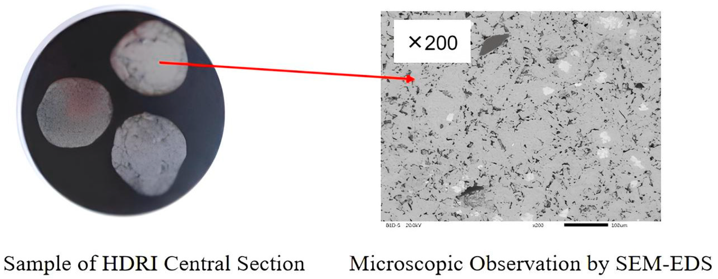
Figure 2.
Temperature diagram of the boundary layer during the melting process.

Figure 3.
Melting process 4 s after the HDRI (300 K) entered the melting pool (1873 K), (a) initial status; (b) generation of the solidified steel layer; (c) melting of the steel layer; (d,e) HDRI bulk melting.
Figure 3.
Melting process 4 s after the HDRI (300 K) entered the melting pool (1873 K), (a) initial status; (b) generation of the solidified steel layer; (c) melting of the steel layer; (d,e) HDRI bulk melting.

Figure 4.
HDRI bonding phenomenon (left) and corresponding temperature distribution (right) with different spacings, having entered the melting pool for 0.8 s.
Figure 4.
HDRI bonding phenomenon (left) and corresponding temperature distribution (right) with different spacings, having entered the melting pool for 0.8 s.
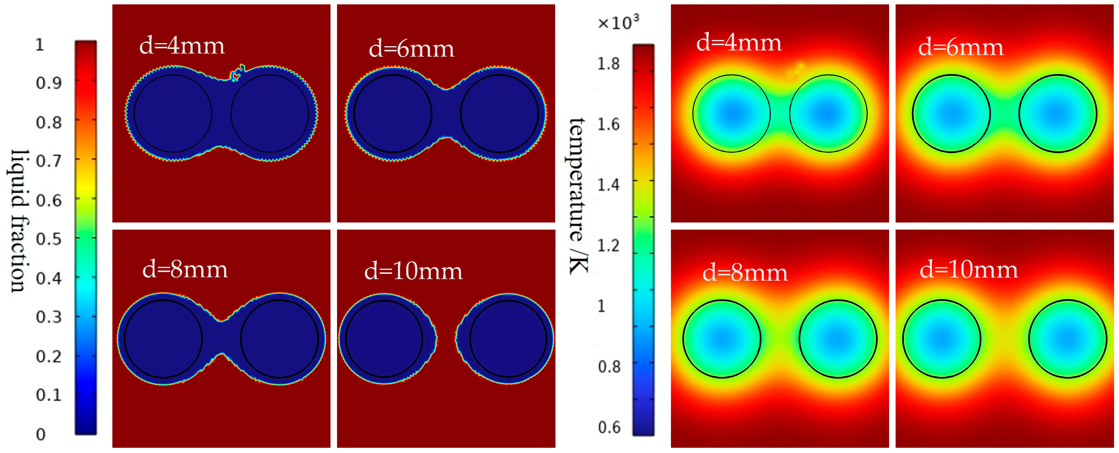
Figure 5.
HDRI bonding phenomenon (left) and corresponding temperature distribution (right) at different molten pool temperatures, having entered the melting pool for 0.8 s.
Figure 5.
HDRI bonding phenomenon (left) and corresponding temperature distribution (right) at different molten pool temperatures, having entered the melting pool for 0.8 s.
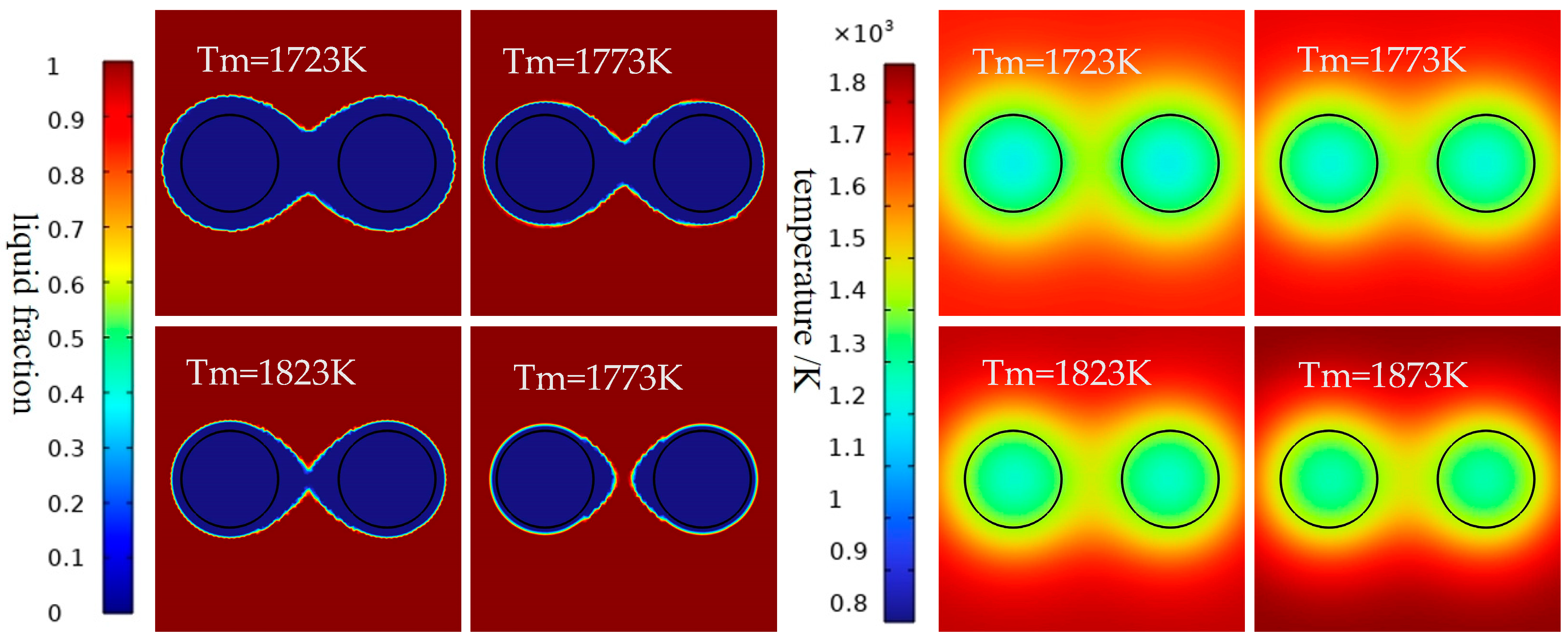
Figure 6.
The HDRI bonding phenomenon (left) and corresponding temperature distribution (right) at different preheating temperatures, having entered the melting pool for 0.8 s, with a spacing of d = 4 mm.
Figure 6.
The HDRI bonding phenomenon (left) and corresponding temperature distribution (right) at different preheating temperatures, having entered the melting pool for 0.8 s, with a spacing of d = 4 mm.
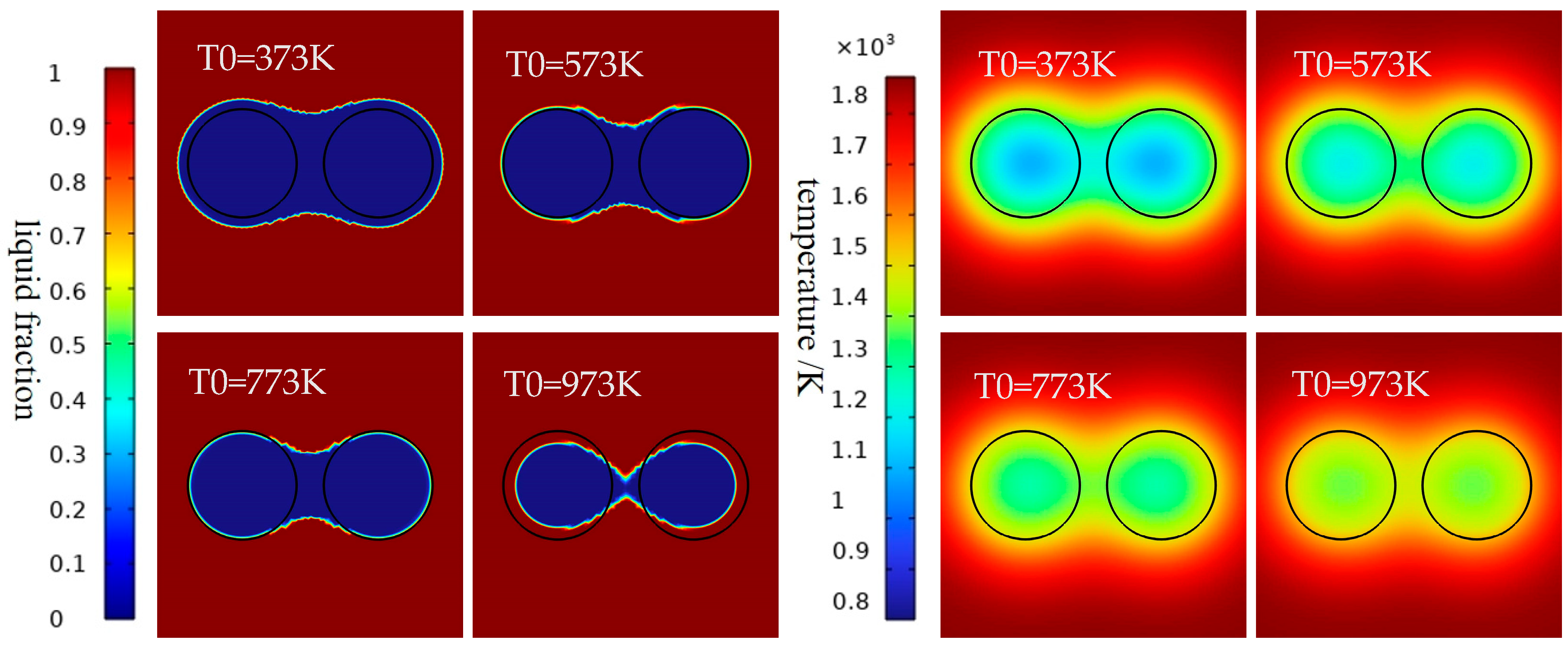
Figure 7.
HDRI bonding phenomenon (left) and corresponding temperature distribution (right) at different preheating temperatures, having entered the melting pool for 0.8 s, with a spacing of d = 6 mm.
Figure 7.
HDRI bonding phenomenon (left) and corresponding temperature distribution (right) at different preheating temperatures, having entered the melting pool for 0.8 s, with a spacing of d = 6 mm.
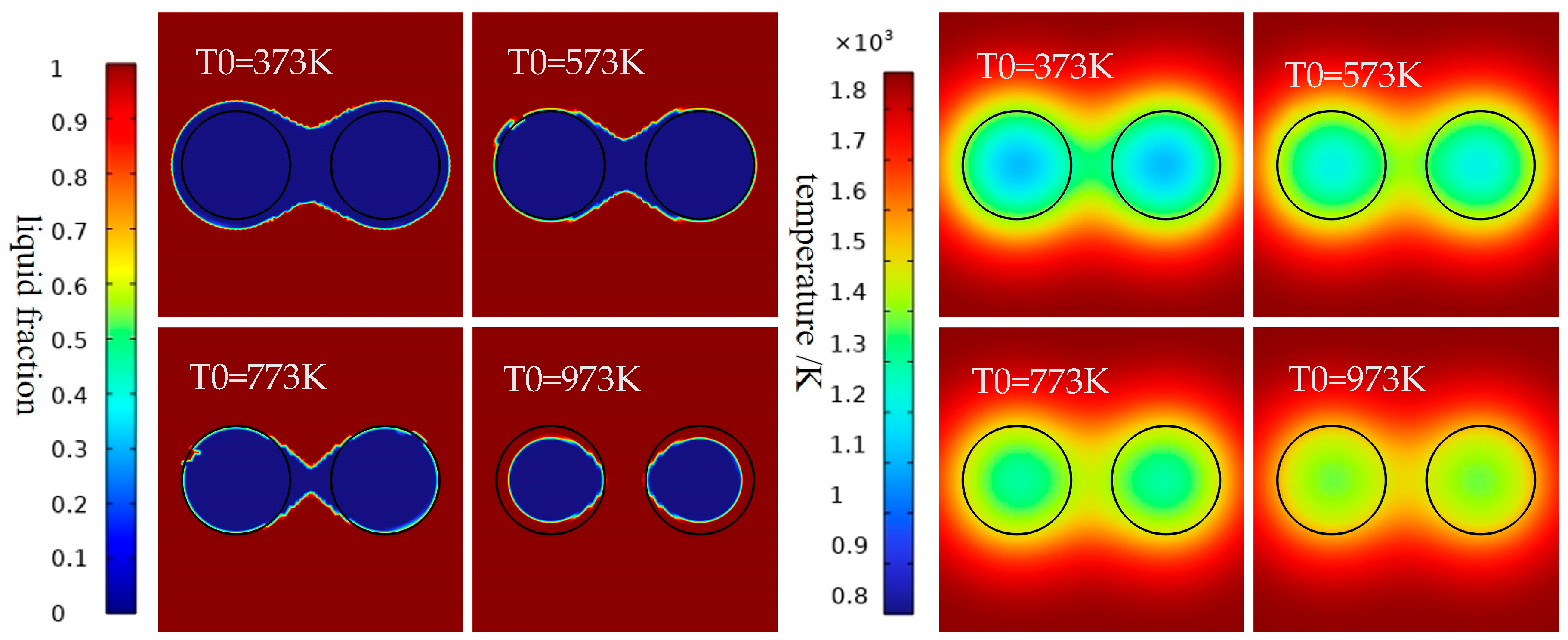
Figure 8.
HDRI melting time at different spacings and at different preheating temperatures.

Figure 9.
Time variation plot of m/m0 with different pool temperatures.

Figure 10.
HDRI melting velocity changes at different melting pool temperatures.
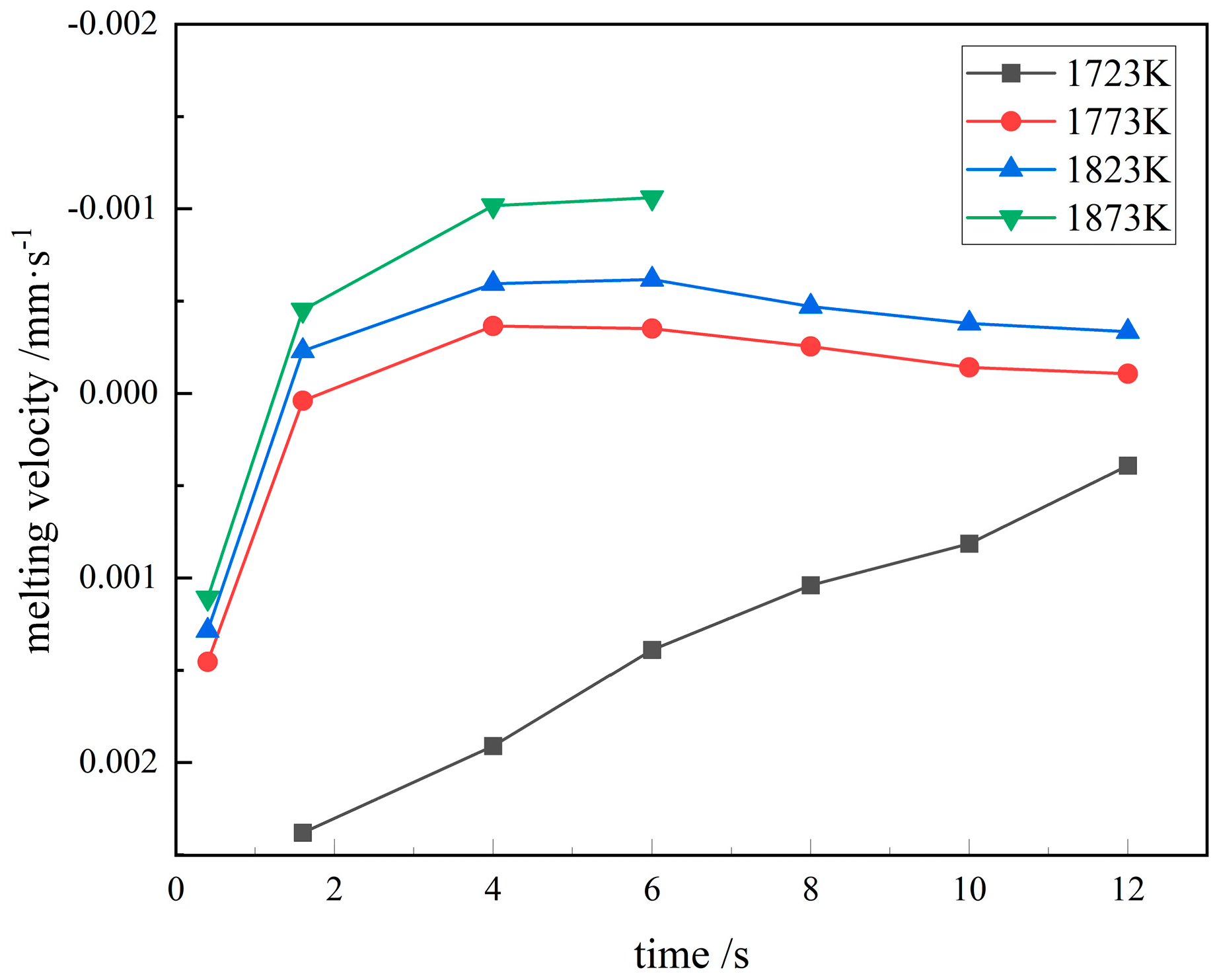
Figure 11.
Rmax/R0 at different the melting pool temperatures.

Figure 12.
The time required for different stages at different melting pool temperatures.

Figure 13.
Time variation plot of m–m0 with different preheating temperatures.
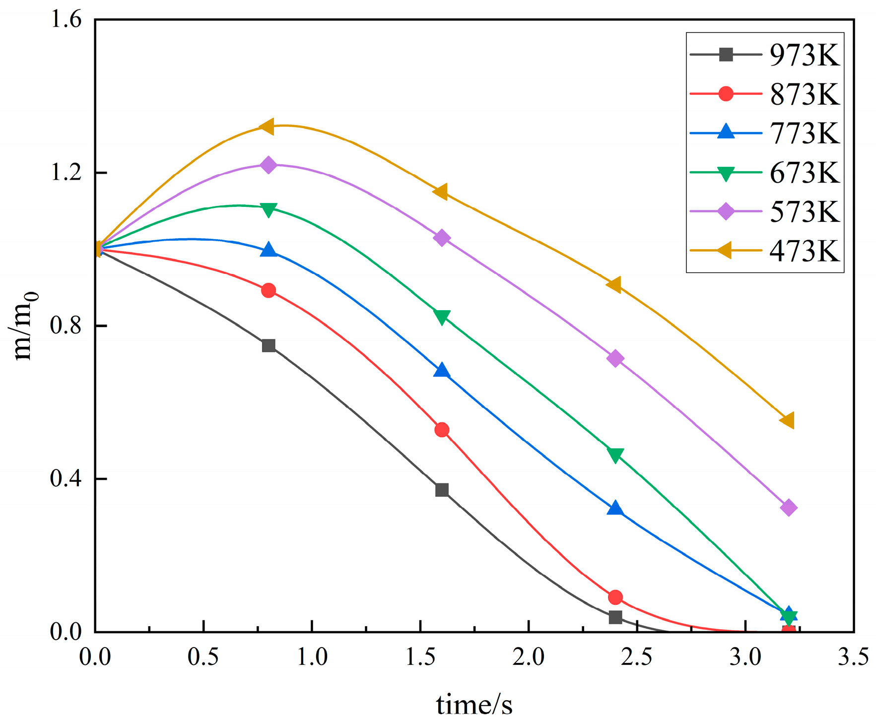
Figure 14.
HDRI melting velocity changes with different preheating temperatures.
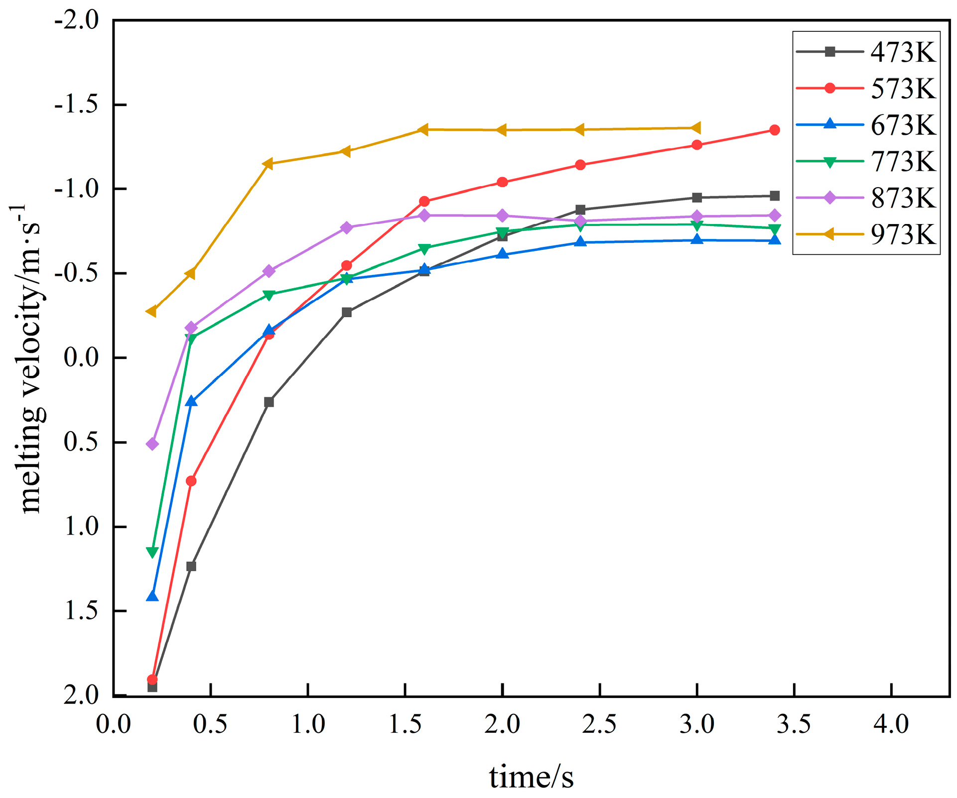
Figure 15.
Rmax/R0 at different preheating temperatures.
Figure 16.
The time required for different stages at different preheating temperatures.

Table 1.
Chemical composition of the HDRI/wt%.
| TFe 1 | FeO | Fe | C | S | SiO2 | P | Cu | Pb | As |
|---|---|---|---|---|---|---|---|---|---|
| 92.42 | 6.60 | 84.94 | 0.29 | 0.002 | 4.290 | ~0.05 | 0.00 | 0.00 | 0.00 |
1 TFe is the sum of iron elements in various forms contained in iron-containing materials [37].
Table 2.
Parameters of properties.
| Parameters of Properties | Value | Unit |
|---|---|---|
| Porosity of HDRI | 0.4 | 1 |
| Density of HDRI | 3000 | kg/m3 |
| Density of liquid steel | 7100 | kg/m3 |
| Heat capacity of HDRI | 450 | J/(kg·K) |
| Heat capacity of liquid steel | 500 | J/(kg·K) |
| Thermal conductivity of HDRI | 35 | W/(m·K) |
| Thermal conductivity of liquid steel | 30 | W/(m·K) |
| Phase transition latent heat | 205 | kJ/kg |
| Viscosity of liquid steel | 0.0065 | Pa·s |
| Melting pool temperature | 1723~1873 | K |
| Initial temperature of HDRI | 300, 473~973 | K |
| Spacing of HDRI | 0~10 | mm |
Disclaimer/Publisher’s Note: The statements, opinions and data contained in all publications are solely those of the individual author(s) and contributor(s) and not of MDPI and/or the editor(s). MDPI and/or the editor(s) disclaim responsibility for any injury to people or property resulting from any ideas, methods, instructions or products referred to in the content. |
© 2024 by the authors. Licensee MDPI, Basel, Switzerland. This article is an open access article distributed under the terms and conditions of the Creative Commons Attribution (CC BY) license (https://creativecommons.org/licenses/by/4.0/).
Share and Cite
MDPI and ACS Style
Lin, X.; Ni, B.; Shangguan, F. Numerical Simulation of the Hydrogen-Based Directly Reduced Iron Melting Process. Processes 2024, 12, 537. https://doi.org/10.3390/pr12030537
AMA Style
Lin X, Ni B, Shangguan F. Numerical Simulation of the Hydrogen-Based Directly Reduced Iron Melting Process. Processes. 2024; 12(3):537. https://doi.org/10.3390/pr12030537
Chicago/Turabian StyleLin, Xiaoping, Bing Ni, and Fangqin Shangguan. 2024. "Numerical Simulation of the Hydrogen-Based Directly Reduced Iron Melting Process" Processes 12, no. 3: 537. https://doi.org/10.3390/pr12030537
Note that from the first issue of 2016, this journal uses article numbers instead of page numbers. See further details here.