

Numerical and Experimental Study on Preheating Burner Characteristics for Peak Shaving
1
School of Automation Engineering, Northeast Electric Power University, Jilin 132012, China
2
State Grid Harbin Power Supply Company, Harbin 150000, China
*
Author to whom correspondence should be addressed.
Processes 2024, 12(2), 346; https://doi.org/10.3390/pr12020346
Submission received: 19 January 2024
/
Revised: 1 February 2024
/
Accepted: 5 February 2024
/
Published: 6 February 2024
(This article belongs to the Special Issue Advanced Low-Emission Combustion Technologies)
Abstract
:With the proportion of renewable energy power in the electricity market gradually increasing, coal-fired power is transforming from primary to basic power, with it providing peak and frequency shaving. However, most current methods for peaking below 50% load have been applied industrially, sacrificing the efficiency of the unit. This is not in line with the goals of energy conservation and emission reduction. Therefore, this study proposes a new preheating-based peaking method. This study experimentally and simulatively explores the flow characteristics, pyrolysis gas law, and NOx emission characteristics of a preheating burner at 40–100% load. The results show that the burner has a significant preheating effect, producing high-temperature char and large amounts of pyrolysis gas. As the load decreases, the burner exit temperature increases, whereas the airflow stiffness decreases. There is little variation in the pyrolysis gas concentration between 40% and 100% loads. The NOx concentration at the burner outlet increases and the reduction efficiency decreases with decreasing load. At 40% load, NOx emissions are 91.53 mg/Nm3 and the reduction efficiency reaches 95.9%. Therefore, preheating is an economical, stable, and low-NOx-emission-peaking method. This study provides theoretical guidance for the application of preheating burners for the 40–100% load peaking of coal-fired units.
1. Introduction
The proportion of renewable energy sources, such as wind and solar energy, has been gradually increasing in the electricity market, following the principles of carbon peaking and carbon neutrality [1,2,3]. However, owing to the strong intermittency and fluctuation of renewable energy used for large-scale power, power grids face enormous peaking pressure to ensure stability [4,5]. Coal-fired power accounted for 35.4% of total global power in 2022 [6]. Owing to its stability, coal-fired power is transitioning from a main power source to a basic power source, providing peak and frequency shaving [7]. It is inevitable that coal-fired power plants will operate at low loads and with load jumping for prolonged periods to achieve power peaking.
With changes in energy demand, coal-fired power is facing new challenges, such as unstable combustion, the low efficiency of denitrification systems, and poor unit economics at low loads [8]. Most coal-fired units are designed for a 70–100% load. Actual loads below 70% reduce combustion stability and even cause the flame in the boiler to turn off. Currently, boiler denitrification systems mainly adopt selective catalytic reduction (SCR) technology [9]. When the load is below 45%, the flue gas temperature at the SCR inlet will be below the active temperature of the catalyst. This reduces the efficiency of the denitrification system, resulting in NOx emissions exceeding acceptable limits [10]. Moreover, when the boiler operates outside its design load, the reduced efficiency of the unit creates additional economic costs.
In recent times, many researchers have focused on the efficient and stable operation of coal-fired units under low loads. Jiang et al. [11] achieved stable combustion and ultra-low pollutant emissions in a 550 MW tangential coal-fired boiler at a 50% load with NOx reduction of approximately 62 ppm by adjusting the burner arrangement, close-coupled overfire air (CCOFA)/separated overfire air (SOFA) distribution, and excess air coefficient. Zhao et al. [12] proposed a new annular fuel–air control strategy to experimentally and numerically investigate the combustion characteristics and NOx emissions of a 1000 MW corner-fired tower boiler at low loads. The new control strategy reduced NOx emissions at the SCR inlet by approximately 20% compared with the original control strategy at 50–100% loads. Chang et al. [13] mitigated the problem of reduced combustion stability and increased NOx emissions at 50% load in a 630 MW tangentially fired boiler by adjusting the burner angles and combinations. The ABDE burner arrangement ensured stable combustion and low NOx emissions (209 mg/m3 at 6% O2). These studies showed that stable combustion and low NOx emissions at 50% load can be achieved by adjusting the combustion method and control strategy. However, there are challenges in operating coal-fired units below a 50% load. Currently, most coal-fired power plants achieve stable combustion at less than 50% of the load in the short term by burning oil or turning on a plasma igniter [14]. Moreover, the SCR inlet flue gas is heated to over 300 °C by the feedwater bypass to enable the SCR to operate efficiently [15]. Most coal-fired power plants cope with peaking below 50% load at the expense of unit efficiency, and the initial NOx emissions are much higher than the emission limits. Therefore, further exploration is required to achieve the goals of high economy, stable combustion, and low NOx emissions during peaking.
Preheating is a cost-effective low-NOx combustion method. In the 1980s, the All-Russian Research Institute of Thermal Engineering [16] proposed, for the first time, a method of natural gas preheating in combination with the air staged combustion technology, which divides the pulverized coal combustion process into three zones: pyrolysis, reduction, and combustion zones. When the preheating temperature reaches 1000 K, NOx emission is reduced by 80% to 138 mg/Nm3 at 6% O2. Afterwards, the US Gas Technology Institute piloted a 0.88 MW test for preheating, with the gas input accounting for 7% to 12% of the total heat input. When the residence time of pulverized coal in the pre-combustion chamber increased from 21 ms to 42 ms, the NOx emission was reduced by 45%. In recent years, there has been rapid development in pulverized coal preheating combustion technology. Rahimipetroudi et al. [17] designed an advanced dual-fuel pulverized coal–natural gas burner based on preheating and co-firing methods, which significantly improved the combustion characteristics and reduced NOx emissions by up to 50%. The Chinese Academy of Sciences [18] conducted an ultra-low NOx combustion test on a 2 MW pulverized coal preheating combustion pilot device, achieving efficient combustion and ultra-low NOx emissions using Shenmu bituminous coal; the calculated combustion efficiency was 99.4% and the initial NOx emissions were 49 mg/m3 at 6% O2. Ouyang et al. [19] investigated the NOx emission characteristics of ultrafine pulverized coal on a 200 kW circulating fluidized bed. The average particle size of pulverized coal was 18.38 μm, and the preheating temperature was 901 °C. The excess air coefficient in the pyrolysis zone, reduction zone, and combustion zone was 0.14, 0.48, and 1.26, respectively. The lowest NOx emission was 92 mg /Nm3, and the combustion efficiency was 97.12%. Lv et al. [20] used a two-stage drop-tube furnace system to study the effects of excess air coefficient, preheating temperature, and combustion temperature on NO emissions and burnout. When the preheating temperature increased to 1200 °C, the unburned carbon content in fly ash and NO emissions were reduced by 43.2% and 48.3%, respectively. Preheating converts the solid fuel into high-temperature char and pyrolysis gas before it enters the furnace, and pyrolysis gas can aid in reducing NOx emissions. The high physical sensible heat of the char and high calorific value of the pyrolysis gas result in quick ignition after entering the furnace, favoring combustion stability and economy. It is clear that preheating combustion technology has the advantage of peaking. In this study, a novel method based on preheating is proposed to address the problems encountered during peaking.
This study is the first to investigate burner preheating characteristics at 40–100% load in detail using an experimental and numerical methodology. First, we analyzed the airflow characteristics and particle motion in the preheating burner under different loads. Subsequently, the pyrolysis gas law was investigated. Finally, we explored the NOx emission characteristics and key factors affecting reduction efficiency. Our findings can provide theoretical support for the application of preheating burners for the 40–100% load peaking of coal-fired units.
2. Model Details
In this study, the preheating burner characteristics at 40–100% load were investigated using experimental and numerical methods. Full-scale thermal state experiments were conducted, and simulations were performed using commercial Ansys Fluent 2020 software (https://www.ansys.com/products/fluids/ansys-fluent (accessed on 21 January 2023)). Emphasis was placed on studying the flow characteristics, pyrolysis gas law, and NOx emission characteristics in the preheating burner through numerical simulations. The plasma was appropriately simplified and equated to 2800 K hot air using energy conservation calculations [21,22,23].
2.1. Physical Model
The structure and grid of the preheated burner are shown in Figure 1. The dimensions labeled in Figure 1a are the same as the actual dimensions of the burner. The plasma igniter diameter is 100 mm. The inlet diameter of the mixture of primary air and pulverized coal is 600 mm, after which it widens to a diameter of 2000 mm, and the outlet of the gas–solid mixture tapers to a diameter of 1000 mm. The overall burner height is 8000 mm. Figure 1b,c show the burner inlet and outlet grids and the cross-sectional grid, respectively, all of which consist of hexahedral-structured cells. The mesh refinement of the central region can accurately describe the combustion. When the number of cells reaches 1,254,627, no significant differences are observed in the calculation results after increasing the number of cells. Therefore, a mesh of 1,254,627 cells is used for all subsequent calculations, considering both computational accuracy and cost. The experimental setup is illustrated in Figure 1d. The experimental equipment includes an air compressor, a coal feeder (error ± 2%), a plasma igniter, and a preheating burner. The measuring instrument consists of a platinum–rhodium type thermocouple (0 °C–1700 °C) and a Testo 350 flue gas analyzer (error ± 0.2 vol%).
Shenhua coal, which is representative of Chinese coal, was selected as the fuel for the experiment. Proximate and ultimate analyses were performed using GB-T212 and GB-T476 standards, respectively [24]. The results are summarized in Table 1. Since the diameter of the particles after grinding is not uniform, in the simulation, it is assumed that the diameter of the particles follows the Rosin–Rammler distribution with a spread parameter of 1.12 [25,26]. The particle diameter ranges from 5.8 to 230 µm with an average diameter of 62 µm. A total of 16,413 coal particles are tracked.
2.2. Mathematical Model
Computational fluid dynamics (CFD) has been widely used to design and improve combustion equipment [27,28]. Numerical modeling is based on the Euler–Lagrange framework for a three-dimensional gas–solid two-phase flow. The gas- and solid-phase conservation equations are solved using the Euler and Lagrange equations, respectively. These two phases couple with each other by exchanging source terms. The semi-implicit method for pressure-linked equations is used for pressure–velocity coupling. The space derivatives of the diffusion terms and stiff nonlinear terms are discretized using central differential and second-order schemes, respectively. The calculation is considered to converge when the energy residual is less than 10−6. The detailed model and parameters are presented in Table 2.
The pre-exponential factor and activation energy of the single reaction rate devolatilization model were determined using the FLASHCHAIN model [29,30]. It is assumed that the char consists of pure carbon and ash and the volatile substance is the virtual substance CaHbOcSdNe [31,32], where a, b, c, d, and e are obtained through mass conservation.
The variation in the specific surface area owing to changes in the pore structure of the particles is one of the main factors affecting the char reaction rate [33,34]. A significant expansion of char pores during preheating was observed using scanning electron microscopy [19,35]. This study introduces the random pore model to correct the char reaction rate. The random pore model assumes that the surface area of the char particles is a function of the char conversion [36]. It is described as follows:
ψ is a pore structure parameter, related to porosity. The value of ψ ranges from 0 to 25, and a typical value of 5 is chosen in this study [37].
The char conversion is as follows:
The char particles are assumed to be spherical with a constant diameter. The Stephan flow and gas-phase reactions within the boundary layer are neglected [36].
The char consumption rate for the reaction r is expressed as follows:
Combining Equations (1) and (3), the char consumption rate is as follows:
This model is able to capture the effect of changes in char pore structure on the reaction rate. The above equations are achieved using a user-defined function (UDF).
2.3. Chemical Mechanism
Many complex chemical reactions, including volatile pyrolysis and combustion and char combustion and gasification, occur during preheating [5,38]. The gas-phase reaction and kinetic parameters are listed in Table 3, where x1–x5 are obtained through mass conservation [39]. Since each reaction has a different Arrhenius rate, the eddy dissipation concept (EDC) model is chosen to describe the interaction between turbulence and chemical reactions. The EDC model assumes that detailed chemical reactions occur in fine turbulent structures [40]. The char reactions and kinetic parameters are presented in Table 4.
3. Experimental Steps and Case Conditions
3.1. Experimental Steps
Primary air is fed by the air compressor with a flow rate of 2.89 kg/s. Primary air carries pulverized coal from the feeder into the preheating burner. The mass flow rate of pulverized coal is controlled by the powder feeder with a mass flow rate of 1.24 kg/s and an error of no more than 0.05 kg/s. Afterward, the mixture of air and pulverized coal is ignited using a plasma igniter, which preheats the pulverized coal in the burner. A thermocouple is inserted 20 mm into the burner outlet side. Pyrolysis gas continuously samples through the tube at the same position. The flue gas is filtered and enters the gas analyzer for analysis. Counting begins after the burner outlet temperature fluctuates by less than 10 K and the pyrolysis gas composition changes by less than 0.2%.
3.2. Case Conditions
Four cases are designed in this study as shown in Table 5. The boundary conditions of Case 1 are the same as the experimental conditions in Section 3.1, and Case 1 is considered the validation case. According to a previous study, the excess air coefficient is maintained at approximately 0.3 to ensure the optimal preheating effect [22]; therefore, the excess air coefficient is controlled at 0.3. The preheating burners are designed for variable loads ranging from 40% to 100%, which represents the current major peaking range. The primary air temperature is 301.5 K, and the relative humidity is 82%. A change in relative humidity will cause a slight change in air composition. The model considers this variation to ensure an overall mass balance.
4. Results and Discussion
In this study, a full-scale preheating burner thermal-state experiment (Case 1) was conducted. The outlet temperature was maintained at around 1040 °C, while the gas-phase products contained 2.93% CH4, 9.53% H2, and 16.83% CO. This result is similar to the experimental results reported by Hui et al. [47,48]. Thermal modification of the fuel occurs at a high ambient temperature, which improves fire performance. Fuel nitrogen (Fuel-N) precipitated under a reducing atmosphere is converted to N2, thereby reducing NO emissions [49]. The experimental results show that the burner exhibits excellent preheating performance.
The deviations between the simulations and experimental results are shown in Figure 2. None of the deviations exceed 6%, which is within an acceptable range and meets the requirements for industrial applications [50]. Simulations can accurately predict the temperature and gas–solid conversion characteristics of the preheating burner. The preheating characteristics at 40–100% load will be analyzed in detail in the subsequent subsections.
4.1. Flow Analysis
Temperature is an important factor for evaluating operational stability [51]. Figure 3a shows the axial temperature, which first increases and then decreases. The primary air carries the pulverized coal into the preheating burner. It is fired by plasma, increasing the temperature rapidly. Since the excess air coefficient is much lower than 1, O2 is rapidly consumed, and the exothermic combustion reaction proceeds until completion. Subsequently, heat-absorbing gasification reactions dominate [52], which is the main reason for the decrease in axial temperature. When the excess air coefficient remains at 0.3, the primary air decreases accordingly as the load decreases. The total heat from the plasma remains constant; therefore, there is an increase in heat absorption per unit mass of flue gas, resulting in an increase in the axial temperature with decreasing load. In addition, dilute pulverized coal is more fully mixed at low loads. The particles collide with each other and break up, increasing the temperature [53]. The outlet temperature at 40% load is 144 °C higher than that at 100% load. This demonstrates that preheated burners can exhibit combustion stability even at 40% load.
Figure 3b shows the axial velocity. There is good correspondence between the axial velocity and temperature. Initially, the thermal movement of the gas molecules accelerates because of the increase in temperature, which leads to a rapid increase in axial velocity. Subsequently, the airflow velocity decreases as the temperature decreases. The velocity of the trailing airflow rises because the shrinking of the tail structure increases the number of collisions between the gas molecules. The exit velocity decreases as the load decreases. Lower airflow stiffness is an inevitable result of operation under low-load conditions.
Figure 4 shows the particle trajectories colored according to the particle residence time. The residence time of the particles significantly increases as the load decreases. This provides a longer time for char gasification at low loads, facilitating the formation of pyrolysis gas and the conversion of Fuel-N. Table 6 summarizes the volatile and char conversions and particle residence times at different loads. The coal pulverized is preheated to more than 1000 °C at the burner inlet under plasma action. All of the volatiles precipitate instantly, and the conversion reaches 100% [17,54]. Some volatiles are burned to provide energy for preheating. The remaining volatiles are pyrolyzed to produce reducing gases under high-temperature conditions. Char conversion increases as the load decreases. On the one hand, the char gasification reaction is promoted by the higher preheating temperature. On the other hand, more char is converted because of the increase in the average residence time of the particles [55,56]. Figure 5 shows the particle trajectories colored according to temperature. At low loads, the particles exhibit a faster heating rate, and the high-temperature region moves toward the burner inlet. Of note, pulverized dilute coal is easier to ignite.
4.2. Pyrolysis Gas Analysis
The main components of pyrolysis gas include CH4, CO, and H2, which exhibit strong reducing properties [57,58]. Figure 6 shows the CH4 mole fraction contours. The CH4 mole fraction is determined using gas-phase reactions R1, R4, and R7. The CH4 distribution corresponds to the high-temperature region, where high temperatures promote the volatile pyrolysis reaction R1 to produce CH4. Since the excess air coefficients are the same for different loads, the gas-phase reaction R4 has little influence on CH4. The hydrolysis reaction R7 has an important effect on CH4, and high temperatures promote R7. Partial CH4 hydrolysis is the main reason for the decrease in CH4, and the elevated CO and H2 mole fractions validate this finding.
Figure 7 shows the H2 mole fraction contours. The formation of H2 is more complex than that of CH4. The volatiles are pyrolyzed to form H2, with H2 then reacting with O2 at the inlet to release heat for preheating. The position of H2 formation advances as the load decreases. This is the result of primary air reduction at low loads. The H2 mole fraction increases with decreasing load. Increasing the temperature promotes the formation of H2 from the gas-phase reactions R5 and R7. Moreover, char pore expansion and a prolonged residence time facilitate the char gasification reaction [20,59], contributing to an increase in H2. Figure 8 shows the CO mole fraction contours. Carbon monoxide is mainly derived from volatile pyrolysis and char gasification. The variation trend and formation mechanism of CO are similar to those of H2 and will not be discussed in this paper.
The pyrolysis gas mole fraction is defined as follows:
The pyrolysis gas concentration is an essential standard for evaluating the effects of preheating [60,61]. Pyrolysis gas is not only a reducing agent that promotes the conversion of Fuel-N to N2, but it also has a high calorific value that enhances char burnout and improves unit economics. This is one of the key advantages of preheating combustion technology [10,47]. Figure 9a shows the gas-phase mole fractions at different loads. The CH4 mole fraction varies significantly at 40% load, decreasing by 70.3%. CO and H2 mole fractions increase by 17.7% and 17.3%, respectively. The decrease in the CO2 mole fraction is a result of the low load promoting the char gasification reaction R2, which results in CO2 reduction and an increase in CO. Figure 9b shows the mole fraction of pyrolysis gas. When the load ranges from 40% to 100%, Xpyrolysis gas exceeds 30% in all cases. Xpyrolysis gas demonstrates little variation as the effective gases increase or decrease. Preheating burners can provide stable pyrolysis gas formation and improve combustion economics at 40–100% load.
4.3. NOx Emissions Analysis
Nitrogen oxide accounts for more than 90% of NOx in the flue gas; therefore, only NO is considered in this study. The NOx emissions are calculated based on 6% O2 in the flue gas [62]. The outlet NOx emissions are shown in Figure 10, which shows that they gradually increase as the load decreases. NOx emissions reach 91.53 mg/Nm3 at 40% load. There are several reasons for this observation. First, the higher temperature causes the formation of more thermal NO. Second, higher char conversion results in more Fuel-N precipitates. Finally, lower CH4 concentrations significantly contribute to higher NOx emissions at low loads. Many studies demonstrate the efficient reduction of NO using hydrocarbons [63,64,65]. Free hydrocarbon radicals combine with NO to form nitrogen-containing intermediates, which are then reduced to N2.
Fuel-N conversion is defined as follows:
where a and b are the volatile conversion and char conversion (%), respectively.
The theoretical mass of fuel NO precipitated is as follows:
where m is coal mass (kg), n is the nitrogen share of coal, and 2.14 is the mass conversion of N atoms into NO molecules.
The reduction efficiency is expressed as follows:
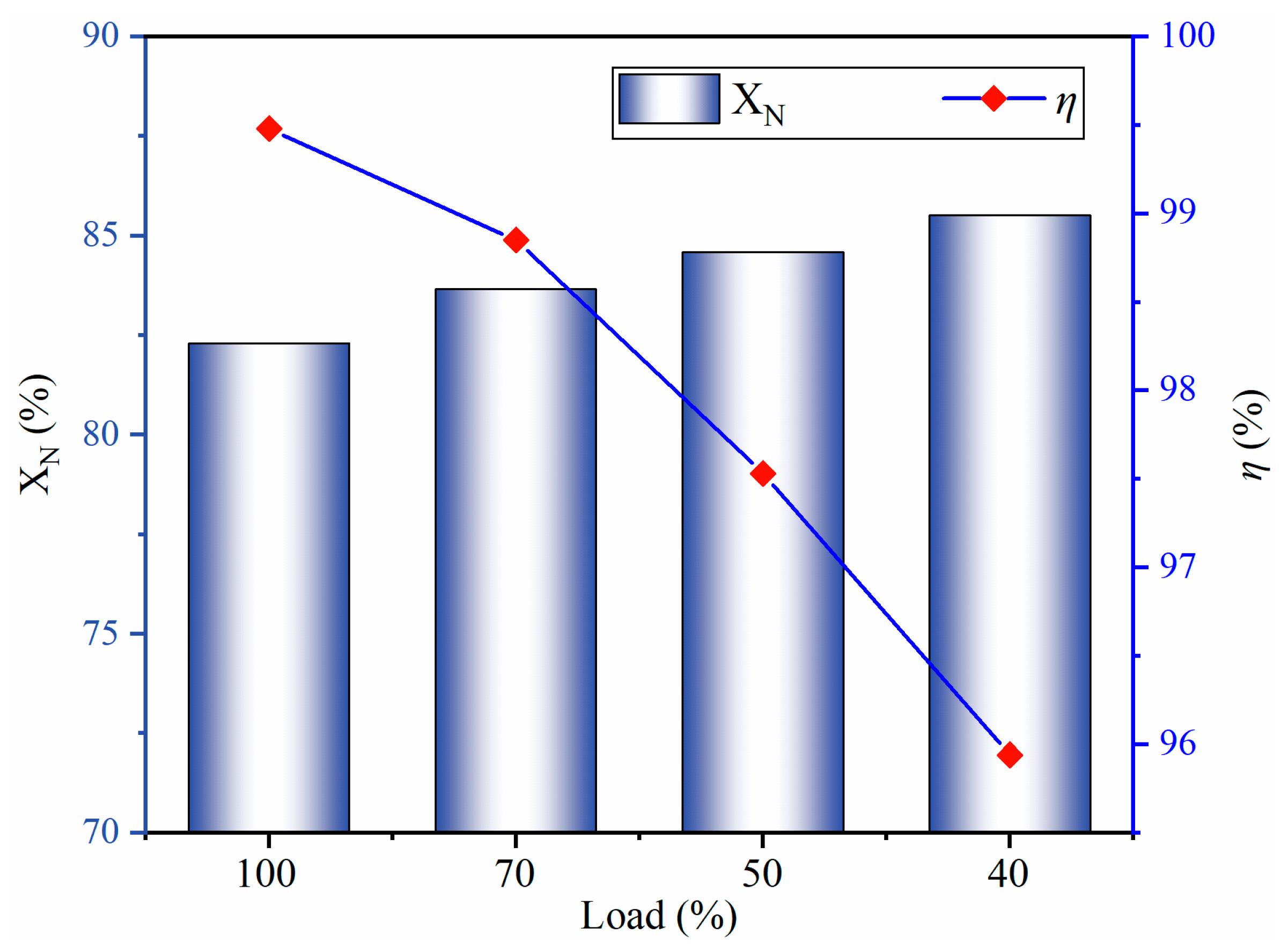
Figure 11 illustrates the Fuel-N conversion and reduction efficiency. To quantitatively analyze the Fuel-N conversion process, we assume that the proportion of volatile nitrogen and char nitrogen precipitated is equal to the conversion of volatiles and char, respectively. Char conversion increases as the load decreases. Hence, Fuel-N conversion increases. The Fuel-N conversion is 85.5% at 40% load. Preheating can precipitate more than 80% of the Fuel-N from the pulverized coal. The reduction efficiency is the ratio of fuel NO that has been reduced to fuel NO that theoretically precipitates. With decreasing load, the input Fuel-N decreases, and the outlet NOx emissions increase, reducing the reduction efficiency. The reduction efficiency reaches 95.9% at 40% load. This study has certain limitations: it explores only the nitrogen removal characteristics of a preheated burner. In future work, boilers should be coupled to evaluate the nitrogen reduction effect of the entire power system. In addition, the examined preheating burner is still in the experimental stage of production and there are related issues including the large size and high cost during power plant retrofitting. In the future, there will be a need to downsize preheating burners and reduce plant retrofitting costs, as well as further reducing NOx emissions.
5. Conclusions
Preheating technology can improve combustion stability and economy and reduce NOx emissions in coal-fired plants. In this study, a novel peaking method based on preheating is proposed to address the problems encountered during peaking. The preheating characteristics at 40–100% load were explored in detail to offer theoretical guidance for the application of preheating burners for peaking. The main conclusions of this study are as follows:
- Preheating is a peaking method with outstanding economy, combustion stability, and low NOx emissions. A preheating burner is capable of consistently producing high-temperature char and large amounts of pyrolysis gas (CH4, CO, and H2) at 40–100% load. With decreasing load, the burner outlet temperature increases and the airflow stiffness decreases. In addition, the particle residence time is extended, and the char conversion increases as the load decreases.
- CH4 hydrolysis results in a decrease in the CH4 mole fraction with decreasing load, and CO and H2 increase in the mole fraction due to volatile pyrolysis and char gasification. Xpyrolysis gas demonstrates little variation at 40–100% load, indicating that the preheating burner can produce pyrolysis gas stably below 50% load.
- The burner outlet NOx emissions are 26.82 mg/Nm3 at 100% load. As the load decreases, NOx emissions increase owing to high Fuel-N conversion and reduced hydrocarbons. NOx emissions are 91.53 mg/Nm3 at 40% load.
- The preheating method precipitates more than 80% of the Fuel-N from pulverized coal. The reduction efficiency decreases with a decrease in load. At 40% load, the reduction efficiency reaches 95.9%.
Author Contributions
Writing—original draft preparation, G.Y.; validation, X.H.; writing—review and editing, H.T.; software, J.Q. All authors have read and agreed to the published version of the manuscript.
Funding
This research was funded by the National Natural Science Foundation of China, grant number 52376096.
Data Availability Statement
The datasets used and/or analyzed during the current study are available from the corresponding author upon reasonable request.
Conflicts of Interest
Author Jianxin Qu was employed by State Grid Harbin Power Supply Company. The remaining authors declare that the research was conducted in the absence of any commercial or financial relationships that could be construed as a potential conflict of interes.
Abbreviations
| SCR | Selective catalytic reduction |
| CCOFA | Close-coupled overfire air |
| SOFA | Separated overfire air |
| UDF | User-defined function |
| EDC | Eddy-dissipation concept |
| Fuel-N | Fuel nitrogen |
| Symbols | |
| Ap | Particle surface area (m2) |
| Ap,0 | Particle surface area at the initial state (m2) |
| x | Total carbon conversion of char particles |
| mp | Particle mass (kg) |
| mp,0 | Initial particle mass (kg) |
| mash | Mass of ash (kg) |
| r | Reaction order |
| mc,r | Mass of char particles consumed for reaction r (kg) |
| Yc | Mass fraction of char in the particles |
| Rr | Rate of particle surface species reaction per unit area (kg⋅m−2⋅s−1) |
| Xpyrolysis gas | Pyrolysis gas mole fraction (%) |
| CH4 | Mole fraction (%) |
| XCO | CO mole fraction (%) |
| H2 | Mole fraction (%) |
| XN | Fuel-N conversion (%) |
| a | Volatile conversion (%) |
| b | Char conversion (%) |
| XVolatile-N | Volatile-N percentage (%) |
| XChar-N | Char-N percentage (%) |
| mT-NO | Theoretical mass of fuel NO precipitated (kg/s) |
| mNO | Mass of outlet NO (kg/s) |
| m | Coal mass (kg) |
| n | Nitrogen share of coal |
| Greek Letters | |
| ψ | Pore structure parameter (dimensionless) |
| ηr | Effectiveness factor (dimensionless) |
| η | Reduction efficiency (%) |
References
- Flamant, G.; Grange, B.; Wheeldon, J.; Siros, F.; Valentin, B.; Bataille, F.; Zhang, H.; Deng, Y.; Baeyens, J. Opportunities and challenges in using particle circulation loops for concentrated solar power applications. Prog. Energy Combust. Sci. 2023, 94, 101056. [Google Scholar] [CrossRef]
- Thengane, S.K.; Kung, K.S.; Gomez-Barea, A.; Ghoniem, A.F. Advances in biomass torrefaction: Parameters, models, reactors, applications, deployment, and market. Prog. Energy Combust. Sci. 2022, 93, 101040. [Google Scholar] [CrossRef]
- Wang, Z.; Yao, G.; Xue, W.; Cao, S.; Xu, S.; Peng, X. A Data-Driven Approach for the Ultra-Supercritical Boiler Combustion Optimization Considering Ambient Temperature Variation: A Case Study in China. Processes 2023, 11, 2889. [Google Scholar] [CrossRef]
- Ali, H.M.; Rehman, T.-u.; Arıcı, M.; Said, Z.; Duraković, B.; Mohammed, H.I.; Kumar, R.; Rathod, M.K.; Buyukdagli, O.; Teggar, M. Advances in thermal energy storage: Fundamentals and applications. Prog. Energy Combust. Sci. 2024, 100, 101109. [Google Scholar] [CrossRef]
- Zhu, S.; Hui, J.; Lyu, Q.; Ouyang, Z.; Liu, J.; Zhu, J.; Zeng, X.; Zhang, X.; Ding, H.; Liu, Y. Experimental study on pulverized coal combustion preheated by a circulating fluidized bed: Preheating characteristics for peak shaving. Fuel 2022, 324, 124684. [Google Scholar] [CrossRef]
- Wayth, N.; Davenport, J. Statistical Review of World Energy; Energy Institute: London, UK, 2023. [Google Scholar]
- Zhang, X.; Cui, X.; Li, B.; Hidalgo-Gonzalez, P.; Kammen, D.M.; Zou, J.; Wang, K. Immediate actions on coal phaseout enable a just low-carbon transition in China’s power sector. Appl. Energy 2022, 308, 118401. [Google Scholar] [CrossRef]
- Sun, Y.; Wang, L.; Xu, C.; Maréchal, F.; Yang, Y. Enhancing the operational flexibility of thermal power plants by coupling high-temperature power-to-gas. Appl. Energy 2020, 263, 114608. [Google Scholar] [CrossRef]
- Liang, Z.; Ma, X.; Lin, H.; Tang, Y. The energy consumption and environmental impacts of SCR technology in China. Appl. Energy 2011, 88, 1120–1129. [Google Scholar] [CrossRef]
- Zhu, S.; Hui, J.; Lyu, Q.; Ouyang, Z.; Zeng, X.; Zhu, J.; Liu, J.; Cao, X.; Zhang, X.; Ding, H.; et al. Experimental study on pulverized coal swirl-opposed combustion preheated by a circulating fluidized bed. Part A. Wide-load operation and low-NOx emission characteristics. Energy 2023, 284, 128573. [Google Scholar] [CrossRef]
- Jiang, Y.; Lee, B.-H.; Oh, D.-H.; Jeon, C.-H. Optimization of operating conditions to achieve combustion stability and reduce NOx emission at half-load for a 550-MW tangentially fired pulverized coal boiler. Fuel 2021, 306, 121727. [Google Scholar] [CrossRef]
- Zhao, S.; Fang, Q.; Yin, C.; Wei, T.; Wang, H.; Zhang, C.; Chen, G. New Fuel Air Control Strategy for Reducing NO x Emissions from Corner-Fired Utility Boilers at Medium–Low Loads. Energy Fuels 2017, 31, 6689–6699. [Google Scholar] [CrossRef]
- Chang, J.; Wang, X.; Zhou, Z.; Chen, H.; Niu, Y. CFD modeling of hydrodynamics, combustion and NOx emission in a tangentially fired pulverized-coal boiler at low load operating conditions. Adv. Powder Technol. 2021, 32, 290–303. [Google Scholar] [CrossRef]
- Gu, Y.; Xu, J.; Chen, D.; Wang, Z.; Li, Q. Overall review of peak shaving for coal-fired power units in China. Renew. Sustain. Energy Rev. 2016, 54, 723–731. [Google Scholar] [CrossRef]
- Xiao, P.; Zhang, Y.; Wang, Y.; Wang, J. Analysis of an improved economizer system for active control of the coal-fired boiler flue gas temperature. Energy 2019, 170, 185–198. [Google Scholar] [CrossRef]
- Rabovitser, J.; Bryan, B.; Knight, R.; Nester, S.; Wohadlo, S.; Tumanovsky, A.G.; Tolchinsky, E.N.; Verbovetsky, E.H.; Lisauskas, R.; Beittel, R. Development and testing of a novel coal preheating technology for NOx reduction from pulverized coal-fired boilers. Gas 2003, 1, 4. [Google Scholar]
- Rahimipetroudi, I.; Rashid, K.; Yang, J.B.; Dong, S.K. Development of environment-friendly dual fuel pulverized coal-natural gas combustion technology for the co-firing power plant boiler: Experimental and numerical analysis. Energy 2021, 228, 120550. [Google Scholar] [CrossRef]
- Liu, J.; Liu, Y.; Zhu, J.; Ouyang, Z.; Man, C.; Zhu, S.; Zhang, Y.; Lyu, Q. Bituminous coal deep regulated ultra-low NOx flameless combustion with fluidized self-preheating fuel: A 2 MWth experimental study. Fuel 2021, 294, 120549. [Google Scholar] [CrossRef]
- Ouyang, Z.; Liu, W.; Man, C.; Zhu, J.; Liu, J. Experimental study on combustion, flame and NOX emission of pulverized coal preheated by a preheating burner. Fuel Process. Technol. 2018, 179, 197–202. [Google Scholar] [CrossRef]
- Lv, Z.; Xiong, X.; Ruan, R.; Wang, Y.; Tan, H. NO emission and burnout characteristics in co-combustion of coal and sewage sludge following high-temperature preheating. Fuel 2023, 331, 125887. [Google Scholar] [CrossRef]
- Yao, G.; Han, X.; Liu, Z.; Tang, H.; Zhou, Y.; Wang, Z. Low-NOx study of a 600 MW tangentially fired boiler based on pulverized coal preheating method. Case Stud. Therm. Eng. 2023, 48, 103156. [Google Scholar] [CrossRef]
- Yao, G.; Liu, Z.; Tang, H.; Meng, L. Prediction of reduction products in the preheating process. Therm. Sci. 2023, 27, 4021–4034. [Google Scholar] [CrossRef]
- Ibrahimoglu, B.; Yilmazoglu, M.Z. Numerical modeling of a downdraft plasma coal gasifier with plasma reactions. Int. J. Hydrogen Energy 2020, 45, 3532–3548. [Google Scholar] [CrossRef]
- Zhang, C.; Zhang, J.; Xu, R.; Zheng, A.; Zhu, J.; Li, T. Numerical investigation of hydrogen-rich gas and pulverized coal injection in the raceway of a blast furnace with lower carbon emissions. Fuel 2024, 356, 129462. [Google Scholar] [CrossRef]
- Wang, H.; Jin, D.; Liu, X.; Zhang, C. Analytical and numerical investigations on the high temperature upgrading solution of subcritical boilers. Appl. Therm. Eng. 2022, 200, 117628. [Google Scholar] [CrossRef]
- Wang, H.; Zhang, C.; Liu, X. Heat transfer calculation methods in three-dimensional CFD model for pulverized coal-fired boilers. Appl. Therm. Eng. 2020, 166, 114633. [Google Scholar] [CrossRef]
- Alobaid, F.; Almohammed, N.; Farid, M.M.; May, J.; Rößger, P.; Richter, A.; Epple, B. Progress in CFD Simulations of Fluidized Beds for Chemical and Energy Process Engineering. Prog. Energy Combust. Sci. 2021, 91, 100930. [Google Scholar] [CrossRef]
- Benim, A.C.; Canal, C.D.; Boke, Y.E. Computational investigation of oxy-combustion of pulverized coal and biomass in a swirl burner. Energy 2022, 238, 121852. [Google Scholar] [CrossRef]
- Jin, D.; Yan, J.; Liu, X.; Zhang, C.; Wang, H. Prediction of tube temperature distribution of boiler platen superheater by a coupled combustion and hydrodynamic model. Energy 2023, 279, 128116. [Google Scholar] [CrossRef]
- Xie, Y.; Liu, X.; Zhang, C.; Wang, H. Numerical investigations on the aerodynamics and flue gas recirculation of cyclone-fired coal boiler. Fuel 2022, 316, 123355. [Google Scholar] [CrossRef]
- Adamczyk, W.P.; Werle, S.; Ryfa, A. Application of the computational method for predicting NOx reduction within large scale coal-fired boiler. Appl. Therm. Eng. 2014, 73, 343–350. [Google Scholar] [CrossRef]
- Yan, J.; Jin, D.; Liu, X.; Zhang, C.; Wang, H. A coupled combustion and hydrodynamic model for the prediction of waterwall tube overheating of supercritical boiler. Fuel 2023, 334, 126589. [Google Scholar] [CrossRef]
- Iwaszenko, S.; Howaniec, N.; Smoliński, A. Determination of random pore model parameters for underground coal gasification simulation. Energy 2019, 166, 972–978. [Google Scholar] [CrossRef]
- Jeong, H.J.; Seo, D.K.; Hwang, J. CFD modeling for coal size effect on coal gasification in a two-stage commercial entrained-bed gasifier with an improved char gasification model. Appl. Energy 2014, 123, 29–36. [Google Scholar] [CrossRef]
- Ding, H.; Ouyang, Z.; Wang, W.; Zhang, X.; Zhu, S. Experimental study on the influence of O2/CO2 ratios on NO conversion and emission during combustion and gasification of high-temperature coal char. Fuel 2022, 310, 122311. [Google Scholar] [CrossRef]
- Fan, C.; Jin, H. A zero-dimensional model of porous char gasification in supercritical water: Experiments and mathematical modeling. Chem. Eng. J. 2022, 440, 135954. [Google Scholar] [CrossRef]
- Haugen, N.E.L.; Loong, B.K.Y.; Mitchell, R.E. Numerical approaches for thermochemical conversion of char. Prog. Energy Combust. Sci. 2022, 91, 100993. [Google Scholar] [CrossRef]
- Zhang, X.; Zhu, S.; Song, W.; Wang, X.; Zhu, J.; Chen, R.; Ding, H.; Hui, J.; Lyu, Q. Experimental study on conversion characteristics of anthracite and bituminous coal during preheating-gasification. Fuel 2022, 324, 124712. [Google Scholar] [CrossRef]
- Cui, K.; Liu, B.; Wu, Y.; Yang, H.; Lü, J.; Zhang, H. Numerical simulation of oxy-coal combustion for a swirl burner with EDC model. Chin. J. Chem. Eng. 2014, 22, 193–201. [Google Scholar] [CrossRef]
- Lupant, D.; Lybaert, P. Assessment of the EDC combustion model in MILD conditions with in-furnace experimental data. Appl. Therm. Eng. 2015, 75, 93–102. [Google Scholar] [CrossRef]
- Westbrook, C.K.; Dryer, F.L. Simplified reaction mechanisms for the oxidation of hydrocarbon fuels in flames. Combust. Sci. Technol. 1981, 27, 31–43. [Google Scholar] [CrossRef]
- Jones, W.; Lindstedt, R. Global reaction schemes for hydrocarbon combustion. Combust. Flame 1988, 73, 233–249. [Google Scholar] [CrossRef]
- Bustamante, F.; Enick, R.; Killmeyer, R.; Howard, B.; Rothenberger, K.; Cugini, A.; Morreale, B.; Ciocco, M. Uncatalyzed and wall-catalyzed forward water–gas shift reaction kinetics. AIChE J. 2005, 51, 1440–1454. [Google Scholar] [CrossRef]
- Ma, J.; Zitney, S.E. Computational fluid dynamic modeling of entrained-flow gasifiers with improved physical and chemical submodels. Energy Fuels 2012, 26, 7195–7219. [Google Scholar] [CrossRef]
- Kajitani, S.; Hara, S.; Matsuda, H. Gasification rate analysis of coal char with a pressurized drop tube furnace. Fuel 2002, 81, 539–546. [Google Scholar] [CrossRef]
- Chen, D.; Zhang, Z.; Li, Z.; Lv, Z.; Cai, N. Optimizing in-situ char gasification kinetics in reduction zone of pulverized coal air-staged combustion. Combust. Flame 2018, 194, 52–71. [Google Scholar] [CrossRef]
- Hui, J.; Zhu, S.; Zhang, X.; Liu, Y.; Lin, J.; Ding, H.; Su, K.; Cao, X.; Lyu, Q. Experimental study of deep and flexible load adjustment on pulverized coal combustion preheated by a circulating fluidized bed. J. Clean. Prod. 2023, 418, 138040. [Google Scholar] [CrossRef]
- Lv, Z.; Xiong, X.; Yu, S.; Tan, H.; Xiang, B.; Huang, J.; Peng, J.; Li, P. Experimental investigation on NO emission of semi-coke under high temperature preheating combustion technology. Fuel 2021, 283, 119293. [Google Scholar] [CrossRef]
- Rahimipetroudi, I.; Rashid, K.; Yang, J.B.; Dong, S.K. Comprehensive study of the effect of a developed co-firing burner and its front-wall, opposed-wall, and tangential firing arrangements on the performance improvement and emissions reduction of coal-natural gas combustion in a boiler. Int. J. Therm. Sci. 2022, 173, 107379. [Google Scholar] [CrossRef]
- Ktistis, P.; Agathokleous, R.A.; Kalogirou, S.A. A design tool for a parabolic trough collector system for industrial process heat based on dynamic simulation. Renew. Energy 2022, 183, 502–514. [Google Scholar] [CrossRef]
- Alobaid, F.; Peters, J.; Epple, B. Experimental measurements for Polish lignite combustion in a 1 MWth circulating fluidized bed during load changes. Energy 2021, 228, 120585. [Google Scholar] [CrossRef]
- Zhu, J.; Ouyang, Z.; Lu, Q. An experimental study on NO x emissions in combustion of pulverized coal preheated in a circulating fluidized bed. Energy Fuels 2013, 27, 7724–7729. [Google Scholar] [CrossRef]
- Zhu, S.; Lyu, Q.; Zhu, J. Experimental investigation of NOx emissions during pulverized char combustion in oxygen-enriched air preheated with a circulating fluidized bed. J. Energy Inst. 2019, 92, 1388–1398. [Google Scholar] [CrossRef]
- Liu, H.; Liu, Y.; Yi, G.; Nie, L.; Che, D. Effects of air staging conditions on the combustion and NO x emission characteristics in a 600 MW wall fired utility boiler using lean coal. Energy Fuels 2013, 27, 5831–5840. [Google Scholar] [CrossRef]
- Gonzalo-Tirado, C.; Jiménez, S.; Ballester, J. Kinetics of CO2 gasification for coals of different ranks under oxy-combustion conditions. Combust. Flame 2013, 160, 411–416. [Google Scholar] [CrossRef]
- Jayaraman, K.; Gokalp, I.; Bonifaci, E.; Merlo, N. Kinetics of steam and CO2 gasification of high ash coal–char produced under various heating rates. Fuel 2015, 154, 370–379. [Google Scholar] [CrossRef]
- Glarborg, P.; Miller, J.A.; Ruscic, B.; Klippenstein, S.J. Modeling nitrogen chemistry in combustion. Prog. Energy Combust. Sci. 2018, 67, 31–68. [Google Scholar] [CrossRef]
- Glarborg, P.; Jensen, A.D.; Johnsson, J.E. Fuel nitrogen conversion in solid fuel fired systems. Prog. Energy Combust. Sci. 2003, 29, 89–113. [Google Scholar] [CrossRef]
- Ding, H.; Ouyang, Z.; Zhang, X.; Zhu, S. The effects of particle size on flameless combustion characteristics and NOx emissions of semi-coke with coal preheating technology. Fuel 2021, 297, 120758. [Google Scholar] [CrossRef]
- Liu, X.; Tan, H.; Xiong, X.; Lv, Z.; Lu, X.; Wang, X. Mechanism study of nitric oxide reduction by light gases from typical Chinese coals. J. Energy Inst. 2020, 93, 1697–1704. [Google Scholar] [CrossRef]
- Yao, Y.; Zhu, J.; Lu, Q. Experimental study on nitrogen transformation in combustion of pulverized semi-coke preheated in a circulating fluidized bed. Energy Fuels 2015, 29, 3985–3991. [Google Scholar] [CrossRef]
- Liu, X.; Zhang, J.; Tan, H.; Mo, Q.; Wang, X.; Wang, Y. Numerical and experimental study on co-firing of low volatile coal in a 330 MW tangentially fired boiler. J. Energy Inst. 2021, 96, 242–250. [Google Scholar] [CrossRef]
- Han, S.H.; Chang, D.; Yang, W. Numerical study on the reburning characteristics of biomass syngas in a 2MW pilot scale heavy oil furnace. Fuel 2016, 181, 277–285. [Google Scholar] [CrossRef]
- Wang, S.; Niu, Y.; Zhu, G.; Ding, Y.; Guo, X. NO formation and destruction during combustion of high temperature preheated pulverized coal. J. Energy Inst. 2021, 99, 82–87. [Google Scholar] [CrossRef]
- Frassoldati, A.; Faravelli, T.; Ranzi, E. Kinetic modeling of the interactions between NO and hydrocarbons at high temperature. Combust. Flame 2003, 135, 97–112. [Google Scholar] [CrossRef]
Figure 1.
Preheating burner structure and grid: (a) structure, (b) inlet and outlet grid, (c) cross-sectional grid, and (d) experimental setup.
Figure 1.
Preheating burner structure and grid: (a) structure, (b) inlet and outlet grid, (c) cross-sectional grid, and (d) experimental setup.
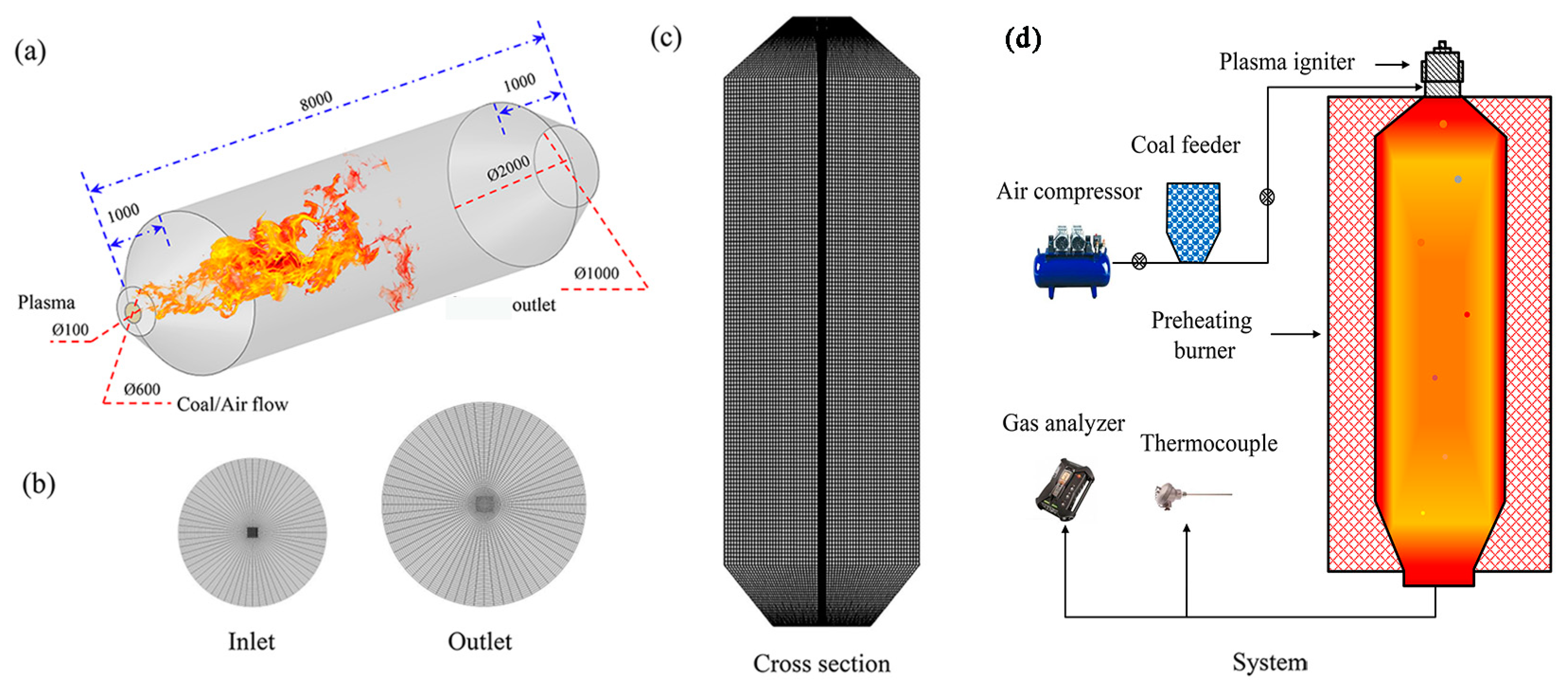
Figure 2.
Deviation of the results from the simulations and experiments.

Figure 3.
Preheating burner axial temperature (a) and velocity (b).
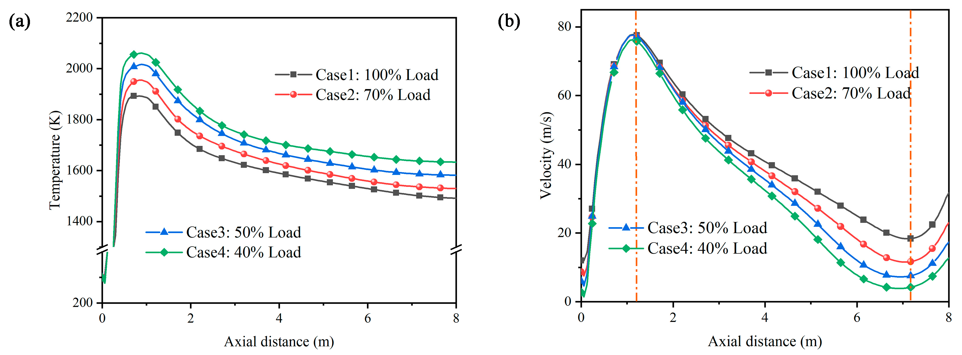
Figure 4.
Coal particle trajectories colored according to particle residence time: (a) 100%, (b) 70%, (c) 50%, and (d) 40% load.
Figure 4.
Coal particle trajectories colored according to particle residence time: (a) 100%, (b) 70%, (c) 50%, and (d) 40% load.
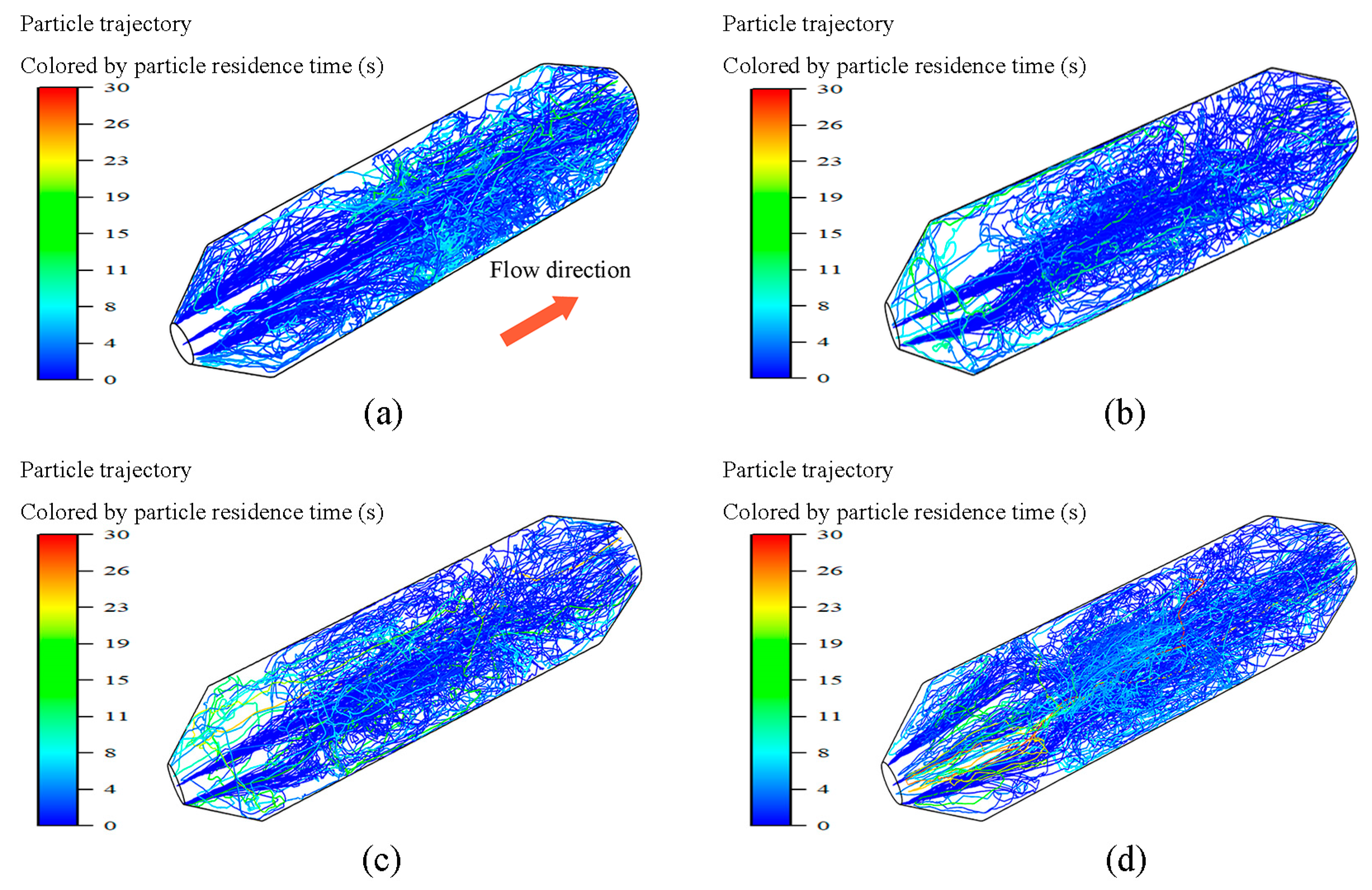
Figure 5.
Coal particle trajectories colored according to particle temperature: (a) 100%, (b) 70%, (c) 50%, and (d) 40% load.
Figure 5.
Coal particle trajectories colored according to particle temperature: (a) 100%, (b) 70%, (c) 50%, and (d) 40% load.

Figure 6.
CH4 mole fraction contours: (a) 100%, (b) 70%, (c) 50%, and (d) 40% load.
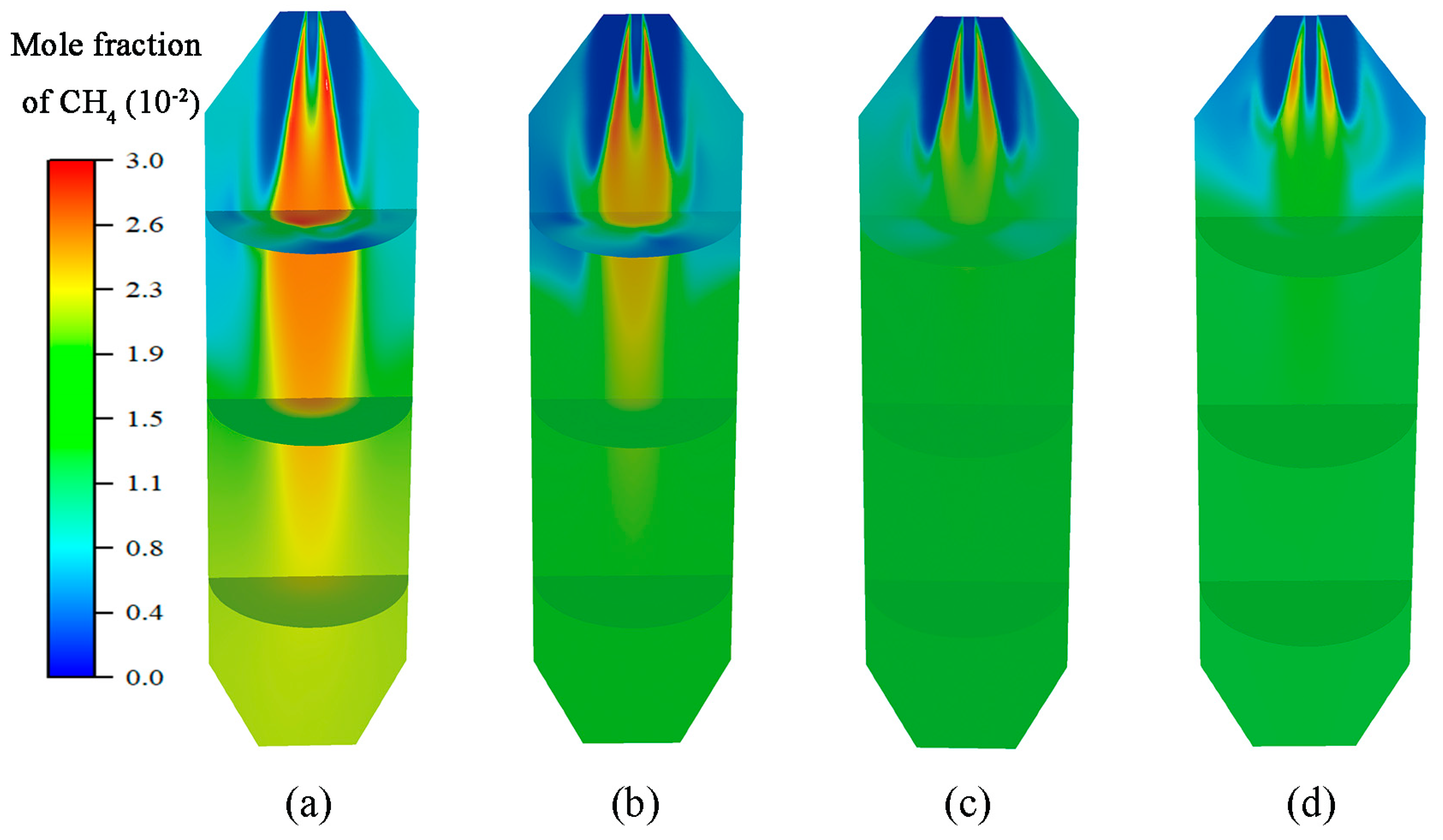
Figure 7.
H2 mole fraction contours: (a) 100%, (b) 70%, (c) 50%, and (d) 40% load.

Figure 8.
CO mole fraction contours.
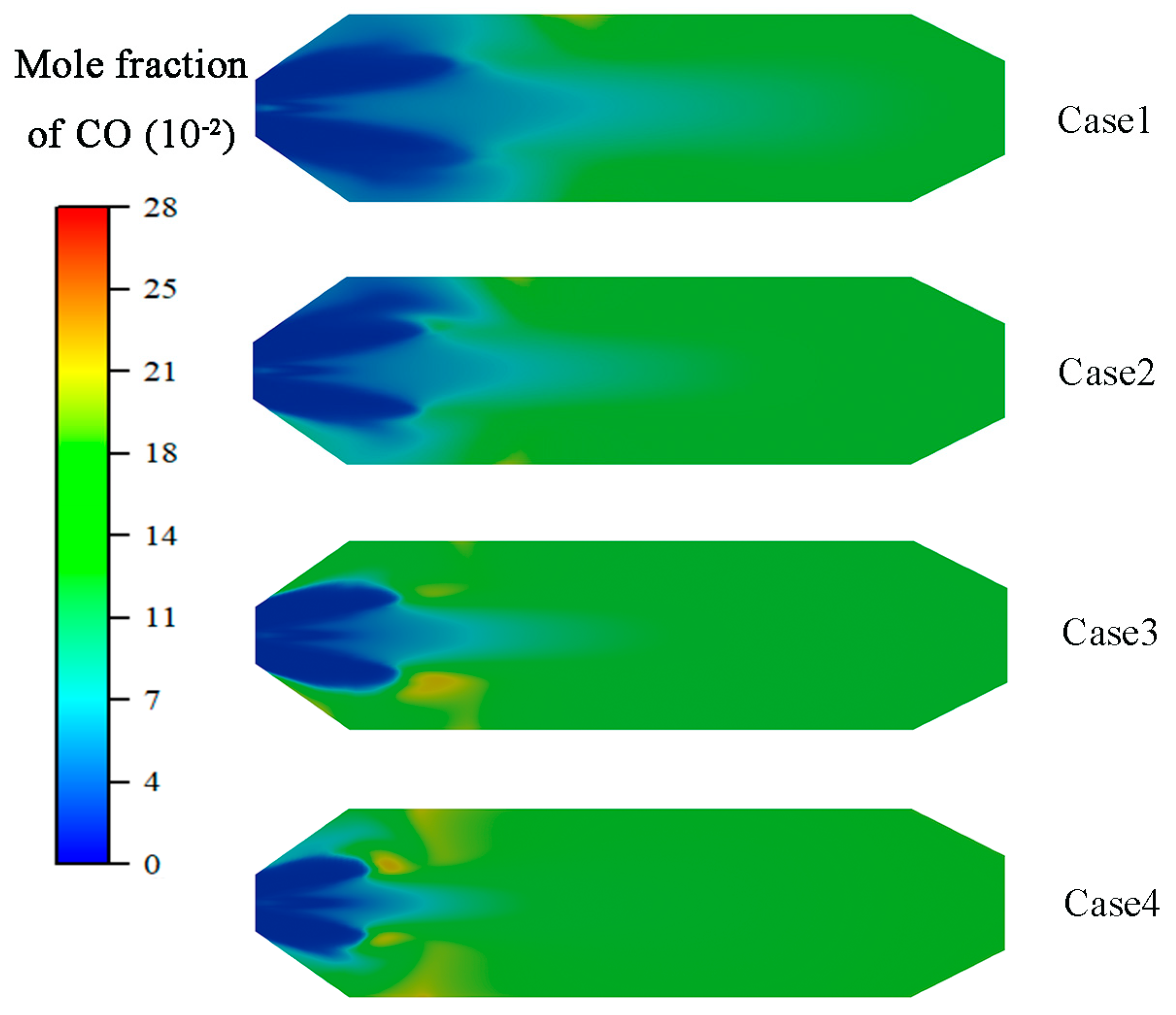
Figure 9.
Gas-phase (a) and pyrolysis gas (b) mole fraction at different loads.
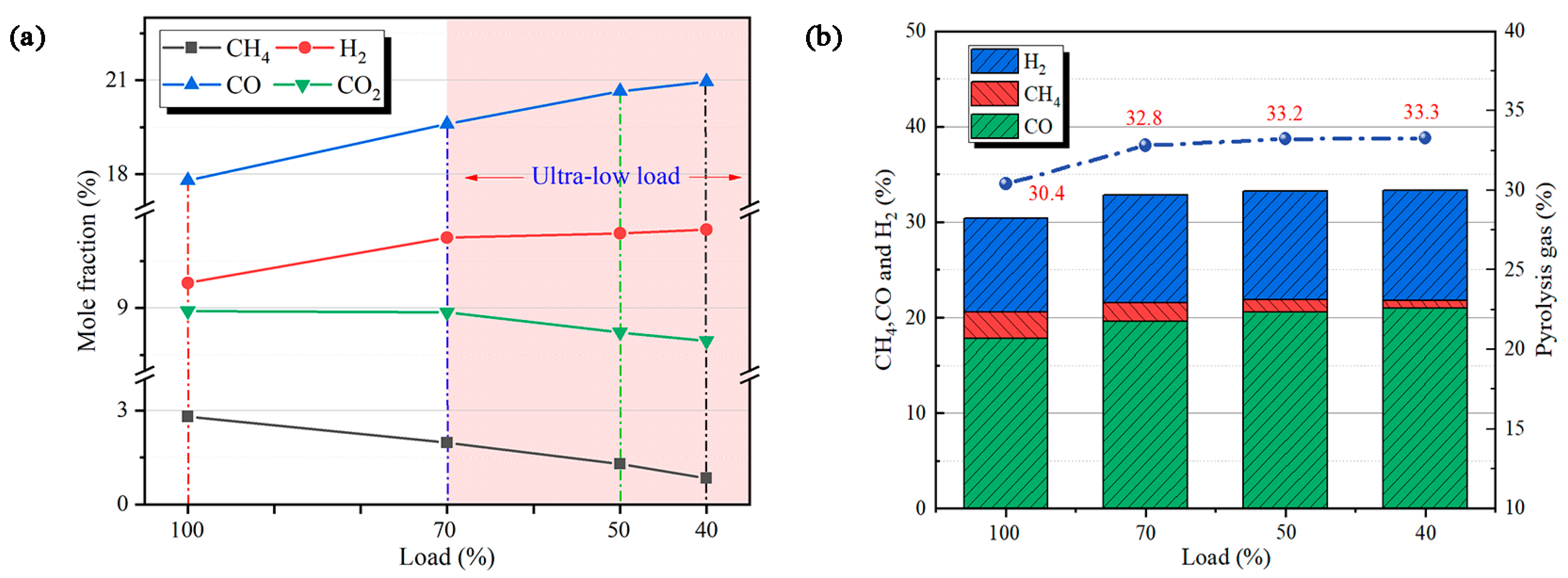
Figure 10.
Outlet NOx emissions.

Figure 11.
Fuel-N conversion and reduction efficiency.

Table 1.
Proximate and ultimate analysis data of Shenhua coal (as-received basis).
| Proximate Analysis, % | Ultimate Analysis, % | ||
|---|---|---|---|
| Moisture | 14.50 | C | 65.10 |
| Ash | 7.37 | H | 3.25 |
| Volatile | 28.67 | O | 8.08 |
| Fixed carbon | 49.46 | N | 0.66 |
| S | 0.71 | ||
Table 2.
Model parameters.
| Item | Model | Parameters |
|---|---|---|
| Turbulence | Realizable k-ɛ model | |
| Radiation | Discrete ordinates model | Theta/Phi divisions 4 × 4 Theta/Phi pixels 2 × 2 |
| Absorption coefficient | WSGGM model | |
| Turbulence–chemistry interaction | EDC model | |
| Lagrangian stochastic tracking | Discrete random walk model | Number of tries: 10 |
| Particle radiation parameters | Emissivity: 0.9 Scattering factor: 0.6 | |
| Devolatilization | Single reaction rate model | A: 41,230 s−1 E: 3.76 × 10⁷ J/kgmol |
| Char reaction model | Multiple surface reactions model | |
| Gas–particle coupling | Particle-source-in-cell method | |
| Thermal NOx model | Extended Zeldovich mechanism | |
| Fuel NOx model | De Soete mechanism | |
| NOx reduction by the char surface | AE: Area of the char surface PNO: Partial pressure of NO | |
| NOx reduction through reburning | k1 = 108; k2 = 1.4 × 10⁶ e−550/T; k3 = 2 × 10⁵ |
Table 3.
Kinetic parameters of gas-phase reactions.
| Gas-Phase Reactions | Ar | Er (J/kmol) | m | a | b | c | Ref. | |
|---|---|---|---|---|---|---|---|---|
| R1 | Vol→x1CH4 + x2CO + x3H2 + x4SO2 + x5N2 | 1018 | 0 | 0 | 0 | 0 | 0 | [23] |
| R2 | CO + 0.5O2→CO2 | 2.24 × 10¹² | 1.67 × 10⁸ | 0 | 1 | 0.25 | 0.5[H2O] | [41] |
| R3 | H2 + 0.5O2→H2O | 6.8 × 10¹⁵ | 1.67 × 10⁸ | −1 | 0.25 | 1.5 | 0 | [41] |
| R4 | CH4 + 2O2→CO2 + 2H2O | 2.12 × 10¹¹ | 2.05 × 10⁸ | 0 | 0.2 | 1.3 | 0 | [42] |
| R5 | CO + H2O→CO2 + H2 | 2.34 × 10¹⁰ | 2.88 × 10⁸ | 0 | 0.5 | 1 | 0 | [43] |
| R6 | CO2 + H2→CO + H2O | 2.2 × 10⁷ | 1.9 × 10⁸ | 0 | 0.5 | 1 | 0 | [44] |
| R7 | CH4 + H2O→CO + 3H2 | 8.0 × 10⁷ | 2.51 × 10⁸ | 0 | 0.5 | 1 | 0 | [44] |
Table 4.
Kinetic parameters of char reactions.
| Char Phase Reactions | Ar | Er (J/kmol) | n | Ref. | |
|---|---|---|---|---|---|
| R1 | C(s) + 0.5O2→CO | 113 | 1.3 × 10⁸ | 0.68 | [45] |
| R2 | C(s) + CO2→2CO | 62.3 | 2.53 × 10⁸ | 1 | [46] |
| R3 | C(s) + H2O→CO + H2 | 0.47 | 1.91 × 10⁸ | 1 | [46] |
Table 5.
Case setup.
| Pulverized Coal (kg/s) | Primary Air (kg/s) | Excess Air Coefficient | Load (%) | |
|---|---|---|---|---|
| Case 1 a | 1.24 | 2.89 | 0.3 | 100 |
| Case 2 | 0.86 | 2.02 | 0.3 | 70 |
| Case 3 | 0.62 | 1.45 | 0.3 | 50 |
| Case 4 | 0.50 | 1.16 | 0.3 | 40 |
a Field test performed.
Table 6.
Summary of particle residue times and conversion.
| Load (%) | Conversion of Particles (%) | Average Residue Time of Particles (s) | ||
|---|---|---|---|---|
| Volatile | Char | |||
| Case 1 | 100 | 100 | 50.97 | 1.87 |
| Case 2 | 70 | 100 | 54.74 | 2.02 |
| Case 3 | 50 | 100 | 57.34 | 2.24 |
| Case 4 | 40 | 100 | 59.89 | 2.43 |
Disclaimer/Publisher’s Note: The statements, opinions and data contained in all publications are solely those of the individual author(s) and contributor(s) and not of MDPI and/or the editor(s). MDPI and/or the editor(s) disclaim responsibility for any injury to people or property resulting from any ideas, methods, instructions or products referred to in the content. |
© 2024 by the authors. Licensee MDPI, Basel, Switzerland. This article is an open access article distributed under the terms and conditions of the Creative Commons Attribution (CC BY) license (https://creativecommons.org/licenses/by/4.0/).
Share and Cite
MDPI and ACS Style
Yao, G.; Han, X.; Tang, H.; Qu, J. Numerical and Experimental Study on Preheating Burner Characteristics for Peak Shaving. Processes 2024, 12, 346. https://doi.org/10.3390/pr12020346
AMA Style
Yao G, Han X, Tang H, Qu J. Numerical and Experimental Study on Preheating Burner Characteristics for Peak Shaving. Processes. 2024; 12(2):346. https://doi.org/10.3390/pr12020346
Chicago/Turabian StyleYao, Guojia, Xiaoju Han, Hong Tang, and Jianxin Qu. 2024. "Numerical and Experimental Study on Preheating Burner Characteristics for Peak Shaving" Processes 12, no. 2: 346. https://doi.org/10.3390/pr12020346
Note that from the first issue of 2016, this journal uses article numbers instead of page numbers. See further details here.