
Applications of Electric Heating Technology in Vehicle Exhaust Pollution Control

1
State Environmental Protection Key Laboratory of Vehicle Emission Control and Simulation, Chinese Research Academy of Environmental Sciences, Beijing 100012, China
2
Vehicle Emission Control Center, Chinese Research Academy of Environmental Sciences, Beijing 100012, China
3
School of Chemical & Environmental Engineering, China University of Mining and Technology (Beijing), Beijing 100083, China
4
The Key Laboratory of Advanced Materials of Ministry of Education, School of Materials Science and Engineering, Tsinghua University, Beijing 100084, China
*
Authors to whom correspondence should be addressed.
Processes 2024, 12(2), 298; https://doi.org/10.3390/pr12020298
Submission received: 26 December 2023
/
Revised: 17 January 2024
/
Accepted: 26 January 2024
/
Published: 30 January 2024
(This article belongs to the Section Catalysis Enhanced Processes)
Abstract
:Motor vehicle exhaust is an important cause of atmospheric pollution. Nowadays, mainstream exhaust emission aftertreatment technologies, such as TWC, DOC, SCR, and DPF, usually require sufficient temperature to perform good purification or maintain normal working conditions. Compared with exhaust gas heating technologies such as engine enrichment and fuel injection, electric heating technology can quickly increase the temperature of exhaust gas aftertreatment devices without adverse effects on engine operating conditions. This article introduces the research and progress of electric heating technology combined with traditional aftertreatment devices on major types of vehicles, such as gasoline vehicles, diesel vehicles, motorcycles, and hybrid vehicles, to improve exhaust purification efficiency and its accompanying fuel consumption impact. In addition, the common structure and characteristics of electric heaters, as well as the current status and development trend of electric heating unit technologies such as electric heating power supply are introduced.
1. Introduction
Air pollution impacts human health [1] and growth [2] seriously. Both internal combustion engine motor vehicles [3] and new energy vehicles [4] contribute to this problem, especially the former, which has a higher emission level. Gasoline engines emit pollutants including carbon monoxide (CO), total hydrocarbons (THC), and nitrogen oxides (NOx). Oxygen-rich combustion of diesel engines results in substantially lower CO and THC emissions but much higher emissions of NOx and particulate matter (PM) than gasoline engines.
Europe [5], China [6], and the US [7] have established strict emission standards to control pollutant emissions, necessitating the development and implementation of various emission pollution control technologies to support the restrictions on emission levels. Taking China’s heavy-duty vehicle emission standards as an example, the CO emission limits in the second to sixth stages of the standards have decreased by 11%, 53%, 67%, 67%, and 67%, respectively, compared to the National First Standard. THC has decreased by 0%, 44%, 58%, 58%, and 88%, respectively, compared to the National First Standard. The proportion of NOx limit tightening is higher, reaching 13%, 38%, 56%, 75%, and 95%, respectively. The proportion of PM tightening is 58%, 72%, 94%, 94%, and 97%, respectively. The increase in the limit of this type of pollution is very significant. Emission pollution can be reduced by upgrading engine technology, improving fuel quality, and purifying exhaust gases. However, because the regulatory standards’ emission limits have recently been cut down to pretty low levels, it is no longer possible to satisfy the standards’ requirements by relying solely on the first two technologies. As a result, aftertreatment technologies for exhaust purification have emerged as a crucial area of research and development. The three-way catalyst (TWC) [8], which can simultaneously remove three different types of gaseous contaminants in the exhaust, is the foundation of gasoline engine emission aftertreatment technologies. Diesel oxidation catalyst (DOC) [9], diesel particulate filter (DPF) [10], and selective catalytic reduction (SCR) [11] are three types of diesel exhaust aftertreatment technology. DOC effectively removes THC and CO from the exhaust and soluble organic fractions (SOF); SCR reduces NOx; and DPF traps PM from diesel exhaust.
In these aftertreatment devices, catalyst devices require sufficient temperature to achieve good purification efficiency, and particulate matter filters also need to be regularly regenerated at high temperatures to maintain good performance. To provide the above favorable temperature conditions, there are various heating methods [12], such as coolant heating, lubricating oil heating, heat storage, electric heating technology, and fuel reforming.
Electric heating technology, which raises the temperature by converting electric energy into heat energy, has drawn much interest from environmental purification specialists and has been used to improve the catalytic purification efficiency of formaldehyde [13], volatile organic compounds (VOCs) [14] and CO [15] in the ambient air. This technology is also used to keep after treatment systems in normal working condition so that they can work efficiently. As of now, only research achievements have been published in this field, lacking systematic summary and analysis, which is not conducive to relevant research and application workers quickly understanding the characteristics, development process, and current situation of exhaust aftertreatment electric heating technology. This review primarily introduces electric heating technology in engine emission control from the perspectives of application purpose and effect, material and structure, placement in aftertreatment devices, type of power supply, and energy consumption.
2. Applications in Vehicle Emission Control
The cold start period in an engine starts from a cold state until the engine temperature reaches normal operating conditions. During this procedure, the low cylinder temperature causes the incomplete burning of the fuel, so that the amount of THC and CO emissions in the exhaust increases [16]. To elevate engine temperature swiftly, the engine control program will actively boost fuel injection, which further increases THC emissions [17]. In addition, during a cold start, the temperature of the aftertreatment unit gradually rises until it reaches a normal level. Another major factor contributing to the rise in pollutant emissions is the limited catalyst temperature at this point, which severely restricts the catalytic performance of catalysts. In conclusion, pollutant emissions during cold start are significantly higher than in regular engine operation. Electric heating technology is currently seen as a potential technological path to meet the needs of new regulatory standards since it can quickly boost the temperature of the aftertreatment unit and significantly minimize cold start pollutant emissions.
2.1. Application to Gasoline Engine Vehicles
Due to the use of fuel injection enrichment as a heating strategy during the cold start stage of gasoline engines, the THC content in the exhaust is much higher than that under normal operating conditions. Before the exhaust temperature reaches the light-off ones of TWC, pollutants, especially THC, cannot be adequately purified, which results in significant emissions [18]. To lower the emissions of THC and CO, electric heaters can quickly raise the exhaust temperature to reach the TWC’s typical operating temperature. This technological solution has been studied and used for decades.
Electric heaters are employed for the exhaust heating and purification tests by Küper P. F. et al. [19]. The electric heater uses rolled metal foil and operates on a 12 V DC power supply with a resistance of roughly 0.06–0.25 Ω and a power range of 0.6–2.4 kW. Through insulating pins, the heater is joined to a support body that has a metal honeycomb structure and is coated with catalysts to serve as an exhaust gas purification system. The main catalyst is installed about 30 cm downstream of the unit. Figure 1 depicts the configuration of the experimental procedure. The results show that in the American Federal Test Procedure (FTP) cycle from engine starting, the exhaust gas and main catalyst temperatures increase significantly by 60 s of electric heating, which greatly accelerates the light-off process of catalyst. In the experiment with the fresh catalyst, the THC decreased from 0.036 to 0.030 g/mi, and the CO decreased from 0.035 to 0.025 g/mi. Meanwhile, the experiment with the aged catalyst also shows a good electric heat-promoting effect.
Brunson G. et al. [20] develop another electrically heated catalyst with a more compact structure to provide a better heating effect. This design eliminates the gap between the heater and the supported catalyst, which allows quick transfer of heat energy to the catalyst by both convection and conduction to speed up the light-off process. As a result, the amount of electricity consumed for the light-off has also decreased. Using electrically heated catalysts with this compact arrangement can minimize the energy consumption of electric heating by about 20–30% while keeping the cold start purification effect.
Similar studies are performed by other groups. Tyagi R. K. et al. [21] test an electrically heated exhaust cleaning system utilizing a three-cylinder gasoline engine. The findings demonstrate that electrical heating considerably increases the TWC purifying efficiency, lowering CO, THC, and NOx emissions by around 70%, 50%, and 50%, respectively. Charles X. et al. [22] evaluate the emissions of a gasoline engine with a TWC and a 1.5 kW electric heater. At high RPM (revolutions per minute) operating settings, electric heating can reduce CO emission concentrations from 0.50% to 0.10% while reducing THC and NOx concentrations from 135 to 83 and 39 to 18 ppm, respectively. The emission characteristics of retrofitted gasoline engines usually change when other fuels are used (such as natural gas or liquefied petroleum gas). In a study on engines burning propane or butane and propane mixtures, Newkirk M. S. et al. [23] find that electric heating technology significantly increases the aftertreatment system’s ability to purify the exhaust, reduces non-methane hydrocarbon in the exhaust by more than 50%, and substantially lowers the likelihood that exhaust components will be involved in photochemical reactions. A study on the application of electrical heating for a compressed natural gas engine is conducted by Coppage G. N. et al. [24]. According to the findings, based on emission data without electric heating, electric heating for 20 s reduces THC emissions by 6% in cold start transient conditions, while heating for 40 s reduces the emissions by another 6%. Electric heating can considerably increase the efficiency of a methane’s purifying reaction, despite its main component being somewhat inactive. At the same time, electric heating has a more significant impact on the purifying effect of CO.
It is not enough to switch on the electric heater immediately after the engine starts to offer a higher beginning reaction temperature for the TWC, and various studies have examined and evaluated the preheating’s potential to reduce emissions. Presti M. et al. [25] design and test a variety of combinations of electrical heating power, heating time, and heating timing in the exhaust purification experiments. When using the same 24 V power supply, preheating for 15 s can raise the temperature of the TWC to 100 °C. Without preheating, this temperature is only around 20 °C, and it takes 40 s after the engine is turned on to reach the same catalyst temperature as the preheating configuration. Therefore, in comparison to the trial without preheating, the introduction of preheating markedly diminishes THC, CO, and NO emissions during the initial cold start cycle of the Economic Commission for Europe (ECE) by 41%, 57%, and 63%, respectively. According to Liu M. et al. [26], who investigate the impact of experimental protocols with and without preheating on exhaust purification, preheating for just 5 s enhances conversion rates for CO, THC, and NOx from 25%, 38%, 63% to 58%, 50%, and 73%, respectively. In addition to improving the purification efficiency, the combination of preheating and postheating methods offers a workable technical solution for lowering the amount of precious metals used in the catalyst and reducing the cost of the aftertreatment device. Some researchers add extra air before the TWC [27] in the early days of electric heating research to solve the low exhaust oxygen content caused by thickening the fuel injection during cold starts and to reduce CO and THC emissions. Due to the low nitrogen oxide emissions during the cold start stage, Bhaskar K. et al. [28] used secondary air, electric heaters, and an oxidation catalyst to solve the problems of CO and THC emissions and achieved good results.
Particulate matter in the gasoline engine exhaust is now drawing more and more attention because of the new regulatory requirements. As far as PM is concerned, compared with traditional gasoline engines, direct injection gasoline engines have significantly higher particulate number (PN) [29] and PM [30] emissions, making it more difficult to meet the standard limit requirements. Therefore, particulate matter filters have also been rapidly developed and applied in the field of direct injection gasoline engine exhaust purification, often known as gasoline particulate filters (GPF). GPF’s regeneration technology is quite similar to that of DPF since the particulate matter collected in them consists of the same components. A 1.3 L gasoline engine platform is used in trials by Xie Y. et al. [31] to regenerate GPF. The electric heater is placed between the oxidation catalyst and the GPF. Numerical relationships are determined in detail among the exhaust flow rate, exhaust temperature, oxygen concentration, NOx, electric heating power needed for filter regeneration, and the oxidation rate of particulate matter.
Electric heating can boost the purification efficiency of exhaust pollutants. As the electricity used originates from the generator driven by the engine, however, it would also inadvertently increase the engine’s fuel penalty. According to Kessels J.T.B.A. et al. [32], the TWC light-off time for a 5-cylinder, 2.3 L multipoint EFI (electronic fuel injection) gasoline engine is roughly 105 s without electrical heating. 2, 4, and 6 g of fuel are consumed when this period is cut by 15, 30, and 55 s, respectively. This fuel penalty is smaller than that for warming up the engine by enriching the fuel injection. In contrast to changing the engine injection method to raise the exhaust temperature, Pace L. et al.’s [33] study discovers that using electric heating technology decreases the fuel penalty. Because increasing the exhaust temperature through enriched fuel injection would increase the exhaust flow rate, and a portion of the energy consumed in the fuel is used to raise the temperature of this additional exhaust. However, increasing the exhaust temperature through electric heating does not have this defect, so it can reduce fuel consumption during cold starts. Additionally, the catalyst warming process is significantly sped up using electric heating.
In order to better predict the impact of electric heaters on the activity of three-way catalysts, Velmurugan D.V. et al. [34] use a control-oriented model to evaluate the cold start of a gasoline vehicle exhaust system containing an electric heater. By combining and comparing electric heating technology with other technical solutions, an optimized cold start scheme for the aftertreatment device can be obtained. This simulation analysis scheme can greatly reduce the development cost of post-processing devices and save development time.
2.2. Application to Diesel Vehicles
Because of their low fuel consumption, strong power, and high torque benefits, diesel engines have been widely utilized in various vehicles, from tiny buses to heavy-duty trucks. The exhaust temperature of diesel engines is often lower than that of gasoline engines with equivalent power, and the cold start procedure is also longer due to the enormous engine size and high air-fuel ratio, which significantly increases the challenge of aftertreatment technology. Correspondingly, the low-temperature activity of exhaust catalysts, such as DOC and SCR, is more important than that of TWC. Electric heating technology has drawn a lot of interest in diesel exhaust purification because it can increase the temperature of aftertreatment devices and improve their purification efficiency.
DOC catalyst, which can remove CO, THC, and some PM from the exhaust, is the most developed diesel aftertreatment technology. It is typically installed at the upstream position of the exhaust pipe, which makes it simple to integrate with the electric heater. Diestelmeier J. [35] looks into how electric heating affects DOC temperature. In his experiments, the electric heater is placed between the turbocharger and the oxidation catalyst. By operating the heater power from 2.4 kW to 4.8 kW and setting the heating temperature at 275 °C during the cold start of a heavy-duty vehicle under the FTP condition, the DOC inlet temperature could be raised to the set temperature and maintained above that temperature in about 250 s. In contrast, it takes the DOC at least 400 s or more to reach that temperature without electric heating. To test the impacts of the parameters of the electrical heating method on the exhaust purifying efficiency, Hamedi M.R. et al. [36] electrically heated the exhaust system of a Euro V standard diesel engine. It has been discovered that heating upstream of the DOC could produce better exhaust cleanup results than heating the DOC carrier directly or heating its exterior. Heating from the 30th to the 50th of the NEDC operating condition can also reduce CO and THC emissions by 47.2% and 17.8%, respectively. The CO and THC emissions can be cut by 70% and 24%, respectively, if an additional short electric heating operation is performed 210 s after a cold start. With the testing system depicted in Figure 2, Duan L. S. et al. [37] install a 1.8 kW electric heater in the exhaust system of a 2.8 L diesel engine. The system’s SDPF is a DPF constructed of aluminum titanate coated with SCR catalyst to purify NOx and PM. The electric heating can elevate the DOC temperature to 200 °C in 450 s to attain the catalytic light-off of THC during the low-load cold start test. The time required for the DOC to reach 200 °C in the WHTC (World Harmonized Transient Cycle) cold start test is reduced from 680 to 262 s. The purifying efficiencies of CO and THC are increased by 92.8% and 50.8% in the low load test and by 39.8% and 38.5% in the WHTC condition, respectively, due to the increased exhaust temperature caused by electric heating. On the other hand, in both tests, the rise of particulate numbers after DOC as a result of electric heating is noted. The slow warming of the SDPF and the vast space between the electric heater and the SDPF prevent the electric heater from significantly enhancing NOx purification during the cold start stage.
Because of the higher exhaust oxygen concentration, higher exhaust flow rate, and lower exhaust temperature, it is more difficult to purify NOx emissions from diesel engines than gasoline engines. Additionally, SCR catalysts are typically installed at the end of the exhaust system, which slows down the warming process. Combining electric heating and SCR has been seen as an effective method to satisfy new emission standards with tighter NOx emission limits. Culbertson D. et al. [38] put several electric heaters (330 V, 6 kW) in front of the SCR catalyst in the exhaust system. In the FTP cycle cold start experiment, it takes the 18 kW electric heaters 188 s to raise the temperature in the middle of the SCR to 200 °C. For 12 kW heaters, the SCR can reach the same temperature after 289 s. However, during this time, the engine’s exhaust temperature is only about 120 °C. The electric heating produces favorable operating conditions that allow the SCR to quickly reach the light-off temperature and perform the purifying function. To heat a two-stage SCR on a 6.7 L Cummins diesel engine platform, Culbertson D. et al. [39] use a DC heater. An urban bus running cycle characterized by lower loads, slower engine speeds, and exhaust temperatures below 170 °C is selected for the experiment. After 1000 s, the temperature between the two SCRs rises to 200 °C, which is high enough for NOx purification. Moon S. and colleagues [40] test the variables that affect electrically heated SCR catalysts and find that the electrical heating power required to keep raising the unit temperature increases as the exhaust flow rate rises. At the fixed exhaust flow rate, the heating power remains unchanged. Pfahl U. et al. [41] conduct experiments with electric heating of diesel car exhaust in NEDC (New European Driving Cycle) conditions, with the electric heater at the upper end of the aftertreatment system consisting of DOC, DPF, and SCR. In a cold start experiment, the electric power is set at 1.9 kW. The DOC and DPF temperatures respond quickly initially, but it is difficult to see how the electric heating affects the SCR catalyst. The catalyst temperature starts to rise gradually only after the heating process ends, and the experimental results show that the electric heating has a significant hysteresis for the warming effect of the SCR at the system’s end. In a 1000-s Artemis Urban Cycle cold start trial, the same device reduced NOx emissions by 67% while being electrically heated for the first 400 and the last 300 s. Similar to this, Menne C. et al. [42] use an electric heater before the DOC, with a considerable delay in the SCR warming process towards the end of the aftertreatment system. The study by Ehrly M. et al. [43] also employs an arrangement of an electric heater upstream, and their purification unit is set up with a tightly connected, small-sized SCR in consideration of the lag in SCR warming. After the cold start, the catalyst can light off quickly with the help of electric heating, which significantly lowers the NOx emissions from the NRTC (non-road transient cycle) test.
A plan is created by Naseri M. et al. [44] to improve NOx conversion. The main goal of the technology is to raise the exhaust temperature using an electric heater to activate the SCR reaction after storing NH3 to saturation in advance on the SCR. This plan can increase the NOx purification rate by up to 98% during the cold start phase of FTP operation. Additionally, electric heating is applied by Feng X.Y. et al. [45] to raise the purification efficiency of vanadium-based SCR. The 3 kW electric heating’s ability to purify NOx is evaluated at several standardized stoichiometric ratios (0.4, 0.6, 0.8, and 1.0) and the gas hourly space velocity (GHSV) of roughly 20,000 h−1. Electric heating may raise the exhaust temperature by around 19 °C and the NOx conversion by about 8%. For example, the warming effect of electric heating on exhaust gas is 16.1–30.4 °C at temperatures below 210 °C, and the corresponding increase in NOx conversion is 6.4–18.7%. Overall, low exhaust temperature conditions make the impact of electric heating on the improvement of NOx purification efficiency more apparent.
On a 6.6 L diesel engine with an aftertreatment unit of an electric heater, DOC, SCR, and DPF in that order, Kim C.H. et al. [46] conducted emission purification research. It takes the SCR about 217 s to attain the operational temperature in the cold start FTP condition trial without heating. Electric heating aids of 2.9 kW and 4.8 kW can shorten the time needed to achieve this temperature to 140 and 95 s, respectively. The light-off time is no longer shortened as the heating power is increased to 5.8 kW. The 2.9 kW heating does not impact the NOx purification efficiency in the first stage of the test cycle, and the 4.8 kW heating can only increase the purification rate by 4.3%. In the second stage, electric heating significantly improved the purifying rate from 53% to 90% and 92.1%, respectively, with 2.9 kW and 4.8 kW heating. There are still many research explorations combining electric heating with SCR. Holz O. et al. [47] combine an electric heater with SCR-coated DPF, shortening the distance between the heater and SCR and reducing NOx emissions by more than 98%. Menne C. et al. [48] combine an electric heater with a two-stage SCR, greatly reducing the time required for catalyst ignition. Hadl K. et al. [49] adopt a similar approach to [49], not only studying the purification of NOx but also specifically examining the emission patterns of nitrous oxide (N2O) during the purification process. Avolio G. et al. [50] find that the combination of electric heaters and SCR-coated DPF can reduce nitrogen oxide emissions in low-speed urban conditions but has a negative impact on fuel consumption. However, under higher speed conditions, not only can nitrogen oxide emissions be significantly reduced, but there is also a significant fuel-saving effect.
Other than the exhaust heating method, Masoudi M. et al. [51] use an electrically heated urea mixer instead of normal electric heating equipment. The mixer has a twisted and curved structure constructed of narrow metal foil. Using a heating power of roughly 140–185 W, the temperature of the SCR catalyst can be quickly raised to 160–195 °C in the FTP low-speed cycle exhaust experiment of a 3.0 L diesel engine, and the NOx conversion of 80–90% is achieved by the SCR that has been pre-stored with urea. Utilizing the electric heating power of 185 W, NOx conversion for SCR without stored urea reaches 95%. This electrically heated urea mixer requires significantly less electrical energy to increase SCR efficiency than conventional electric heaters. Additionally, urea deposition at the mixer site can be minimized.
Electric heating is often combined with engine management technology to improve pollution-cleaning performance and fuel efficiency. The efficiency of electric heating in conjunction with the air/fuel ratio and spark advance is validated by Zobel T. et al. [52] The findings indicate that NOx emissions may rise as electric heating time increases when utilized only with the air/fuel ratio adjustment method. On the other hand, when employed alone or in conjunction with changing the air-fuel ratio and ignition advance, good NOx cleanup outcomes can be produced. Electric heating and cylinder deactivation are integrated by Matheaus A. et al. [53], who discover that the program not only reduces emissions in a good way but also reduces fuel usage by roughly 44%.
In order to better develop aftertreatment devices assisted by electric heating, Ciaravino C. et al. [54] used program simulation methods to calculate the heating effect of the electric heater on the aftertreatment device and compared it with actual exhaust experiments. The results show that the simulation method used accurately infers the heating effect of the electric heater on the aftertreatment device under transient operating conditions, providing good conditions for promoting the development and application of electric heating technology.
DPF is an efficient treatment technology for diesel exhaust particulate emissions, and DPF regeneration is a crucial assurance of steady operation [55]. Under most operating conditions, diesel injection and combustion [56] or oxidation [57] can achieve DPF regeneration; nevertheless, the technology is complex and the energy consumption is considerable. At the same time, extra ultrafine particles and gaseous pollutants are produced during the DPF regeneration. Adopting in-cylinder injection also results in oil dilution, which impacts the diesel engine’s dependability and safety [58].
The electric heating can raise the temperature of DPF swiftly to realize a smooth regeneration without the drawbacks of traditional regeneration methods. Fang J. et al. [59] study the interactions and variety of regulation of various indicators, such as air flow rate, heating temperature, the mass of PM captured, regeneration temperature, and regeneration time, and optimize key DPF parameters, such as transition length. Meng Z.W. et al. [60] developed a simulated DPF regeneration research system and studied the impact of the connecting components between the electric heater and DPF on the regeneration performance through this system. Later, further research [61] is conducted on the characteristics and interrelationships of each stage of the regeneration process, and based on this, an optimized regeneration plan is formulated. Zhong C. et al. [62] achieve DPF regeneration at lower temperatures by combining electric heating technology with catalytic DPFs. DPF regeneration is possible in the investigation in both cold start and high-speed situations using electric heating. However, in the cold start case, compared to the high-speed condition, the DPF end’s warming response is slower, and it takes more time to initiate particle combustion when the electric heater is turned on. Additionally, the increased gaseous pollutant concentration in all temperature ranges encourages the quick completion of catalytic regeneration by electric heating.
2.3. Application to Motorcycles
Even though motorcycles release relatively tiny emissions, they emit rather large amounts of pollutants. Limited by the narrow space and generally low overall cost of the exhaust system, it is far more challenging to treat a motorcycle’s exhaust pollution than that of cars or off-road machinery. Researchers typically pick tiny electric plugs as electric heating components for motorcycle exhaust purification since standard electric heaters are too bulky to be fitted in short motorcycle exhaust pipes. Horng R. F. et al. [63] use electric plugs to heat motorcycle exhaust catalysts and study the relationship between heating position and effect. They find that the purification rate of the catalyst increases slowly when heated in the middle of the catalyst [64]. Moreover, when the concentration of CO in the exhaust is high, electric heating can promote the rapid release of heat from the catalytic reaction, thereby accelerating the catalyst ignition process. When the CO content in the exhaust is below 1% [65], electric heating does not promote the operation of the catalyst at all.
In other studies, Mianzarasvand F. et al. [66] heated the catalyst and exhaust using electric plugs. The results also demonstrate that positioning the electric plug in front of the TWC can produce better heating outcomes than placing it in the middle of the catalyst. As the engine starts, the four heating schemes of 20, 30, 35 s, and continuous heating are compared. It has been discovered that heating for 35 s may produce the best CO purification effect and a constant heating effect. In addition, this program can lower the system’s power consumption compared to continuous heating.
Khan S. R. et al. [67] investigate a method combining electrical heating and phase change materials (PCM) to reduce the cold start emission. When the engine starts up after a long engine off period, the electric plugs heat the catalyst quickly. After the light-off period, the heat transfers from the catalyst to the PCM gradually. Then the solid PCM melts, and the heat is stored in it. After the engine is shut down, the heat of the after treatment system emits little by little. The PCM returns to solid and releases heat that can maintain the catalyst temperature within a period. If the engine is started up again during this period, the catalyst can purify the pollutants immediately and save the electric energy used to heat the system.
In addition to directly heating the exhaust and catalyst, Raja A.S. et al. [68] use electric plugs to heat the intake air, indirectly increasing the exhaust temperature and also achieving good improvement effects for exhaust purification.
2.4. Application to Hybrid Vehicles
Hybrid electric vehicles (HEVs) combine the power of electric motors and traditional internal combustion engines (diesel or gasoline) to operate. The internal combustion engines of HEVs also cause the issue of exhaust pollution, and the purification technique used is the same as that used in common internal combustion engine vehicles. As a result, the aftertreatment system of HEVs can also use electric heating technology. HEVs, as opposed to conventional internal combustion engine vehicles, have battery packs with greater capacity that can sustain higher power and longer electric heating processes, which is beneficial to improving the purification effect of the aftertreatment device. When the state of charge (SOC) of the battery is high or the vehicle power demand is not high, hybrid vehicles can drive on motor power alone. So, its internal combustion engine is only a stage of work to charge the battery pack or supplement the electric motor to provide the vehicle’s power. After completing the task, the internal combustion engine is turned off, waiting for the next time there is a demand for work, and then starts up again. HEV aftertreatment systems frequently undergo a cold start procedure due to the aftertreatment unit’s slow cooling between jobs, resulting in higher cold start performance requirements than those of a conventional gasoline or diesel vehicle. Wei H.B. et al. [69] apply a kinetic model of the exhaust catalyst, which in turn includes a thermodynamic model, an oxygen storage model, and a purification efficiency calculation method, to more precisely analyze the exhaust thermal environment scenarios of HEVs and formulate the electric heating scheme. The team used the mathematical model to develop the aftertreatment device’s heating curves and corresponding pollutant purification efficiencies. The heating effect of the catalyst at various locations is also predicted. It has been discovered that future power fluctuations vary significantly when electric heating is turned on at different battery pack charge levels. Effective control of the HEV’s battery pack’s stored energy guarantees the vehicle’s smooth operation. The engine start-stop procedure of the hybrid vehicle can be sensibly constructed if the destination and length of the trip are known in advance, and the cold start process can be sped up by preheating the aftertreatment device. Deng T. et al. [70] use a calculation model similar to that of Wei H.B. et al. [69] to analyze the effect of heating process control on battery pack power using a logic threshold control strategy and an engine start-stop optimization control strategy. The results show that the combined preheating and engine start-stop optimization control strategy can significantly reduce CO and THC emissions at the cost of minor energy consumption. Bargman B. et al. [71] test a hybrid gasoline car in real-world driving conditions to confirm the impact of the preheating procedure on exhaust cleaning. During the first 150 s of the cold start phase in the US06 cycle, electric heating decreases the overall emissions of THC and NOx by 43% while maintaining the SOC at no less than 25%. At various initial SOC levels, Sivakumar S. et al. [72] study the impact of different electric heating systems on fuel consumption and pollution reduction. The findings demonstrate that when the SOC value is high, specific heating plans with higher power and short preheating times (or no preheating) may increase the fuel penalty. At different SOC levels, however, implementing a suitable preheating program can significantly lower pollutant emissions and increase fuel consumption by only 1%. With the current form of increasingly strict greenhouse gas emission limits, HEVs with good fuel economy will obtain more and more attention, and their pollution control technology will inevitably become a focus of the future research stage. Canè S. et al. [73] conducted an experimental validation of preheating technology in diesel exhaust purification systems. For a hybrid car with a 2.3 L displacement engine, NOx emissions drop when the preheating power is raised from 2 to 3 kW. However, the further emission reduction effect of increasing the heating power to 4 kW is not significant. NOx emissions decrease as the preheating time is extended for various preheating powers. Still, they all achieve equilibrium in 100 s, and further developing the preheating time has no better impact on the NOx reduction effect. The application of electric heating technology in this field will undoubtedly become a crucial technical component to resolve the pollution problem of HEVs.
3. Structure of Electric Heaters
The critical component of electric heating technology is the electric heater, which raises the temperature of the aftertreatment device and supports its practical and reliable purifying performance by converting electrical energy to heat energy via the Joule effect. The key parameters of an electric heater, including structure, material, and bonding method, have a significant impact on the heating effect. Among them, the differences in structure are the most intuitive and can serve as the main basis for distinguishing the types of electric heaters. It is very difficult to have a good heating impact if the heater’s volume and mass are too small to allow for the timely diffusion of heat energy. It is also challenging to heat quickly to achieve the effect of aftertreatment device warming if the volume is too high, as in the early period of electric heating, energy is mainly utilized in increasing its own temperature [74]. Additionally, the structural form directly impacts the heater’s manufacturing difficulties and lifespan. As a result, achieving good electric heating efficiency is based on and guaranteed by the heater’s perfect structural design.
Metal honeycomb electric heaters are often made of ferrochrome aluminum. The heating material is formed into flat or corrugated sheets with various curvatures and then combined and rolled into shape. Sinusoidal cross-sectional holes then surround the neighboring sheets, and the interior space is divided into a consistent through-aperture structure, giving the heater’s appearance a honeycomb body style [75]. In this literature, the authors also compare the influence of different pore shapes on the heating effect and find that the use of herringbone-shaped holes in the heater has a better heating effect than traditional sinusoidal-shaped holes, which can improve the purification efficiency of THC. In terms of hole density, when using a 400 hole/square inch heater, the THC emissions are significantly lower than those in experiments using a 160 hole/square inch heater. Therefore, increasing the hole density of the heater appropriately can also achieve better heating effects. The honeycomb heater’s cross-section is divided into various heating zones using flexible insulation techniques to achieve the ideal heating power and heat distribution, such as an S-shape [76] and spiral form [77]. Figure 3 shows the structure and manufacturing method of a honeycomb electric heater. Air insulation [78] and insulating coatings [79] are the main insulation methods. Electric heaters in the shape of rings have also become more common in recent years to increase the heater’s heat homogeneity and maintain stable temperature conditions for the catalyst in the back [80]. The honeycomb body of an electric heater resembles a thin disk at shorter lengths, and the high-speed exhaust flow may cause the heating material inside to vibrate and deform, leading to additional deterioration or damage. A fastening device must be used to support the heating material securely; if the support body is metal, the fixing device should be an insulator, such as ceramic [19].
Another typical technique for creating metal honeycomb heaters is extrusion [81]. Developing a high-performing honeycomb body with minimal porosity is feasible by extruding a molten powdered-state metal material, typically made of a ferrochrome aluminum alloy [82]. To achieve the desired direction of electric current and the ideal heat distribution to adjust the honeycomb resistance, slits of a specific length and width can be cut in the honeycomb’s outer edges. Through these slits, the honeycomb body can then be divided into meandering and zigzagging current channels [83]. Figure 4 illustrates the structure and current flow pattern of an extrusion electric heater.
The most conventional type of electric heater is a honeycomb heater. As common TWC, DOC, and SCR catalysts have structures similar to honeycomb heaters, it is simple to utilize or merge them. Therefore, this sort of electric heater was the first to be researched and applied throughout the early days to both gasoline vehicles [84] and diesel vehicles [85].
The heat sealing band is a well-known electric heater that can also be utilized in exhaust heating technology, which is developed by HJS Emission Technology GmbH and Co [51]. In such a heater, the heating strip is repeatedly bent to form a bow-shaped structure, enhancing the contact between the exhaust and the heater to achieve rapid heat transfer. Due to the relatively large width and thickness of the heating belt, this type of heater is more stable and sturdy compared to honeycomb heaters and wire heaters and is suitable for application in vehicle exhaust aftertreatment devices with severe vibration and bumps. Based on that, the company creates a high-efficiency SCR system for NOx purification, which, in operational testing, considerably improves catalyst light-off characteristics and decreases NOx emissions [86].
Metal mesh is convenient to process, and its resistance can be easily adjusted through stretching and compression. Such a grid can be rolled into a cylindrical electric heater, and a small-volume catalyst can be placed inside it. This surrounding heater can quickly raise the catalyst temperature to reduce the cold start time. For gasoline engine exhaust purification studies, Sendilvelan S. et al. [87] use such a heater with an oxidation catalyst, significantly increasing the CO and THC purification rates. They [88] also study the effect of secondary air on the process of electric heating catalytic purification and find that a moderate amount of supplementary air significantly improves the purification effect of THC. Li W. et al. [89] successfully purify NOx by coating a V2O5-WO3/TiO2 SCR catalyst onto a metal grid that serves as an electrically heated catalyst.
The most typical heating component is heated wire, which has been utilized in studies on exhaust gas purification. To raise the exhaust temperature by 1000 to 1500 W electric heating power, Aktas F. et al. [90] wrap the electric heating wire around the outside of the exhaust pipe. The outcomes demonstrate that this program can dramatically lower CO and THC emissions over the TWC. However, the study uses a 220 V AC power supply, which is much larger than those in vehicle applications. Konagai N. et al. [91] coat the Co3O4 catalyst on the spiral ferrochrome aluminum heating wire by the sol-gel method so that the electric heating energy can be directly transferred to the catalyst to achieve a rapid light-off. The NOx, THC, and CO conversions of the electrically heated catalyst in the simulation experiment are 34.1%, 18.7%, and 6.5%, respectively. Zhu S. et al. [92] use an electric heater to regenerate the DPF by coiling the electric heating wire around the filter’s edge. The regeneration efficiency of the filter is greater than 87%. A similar technique is used by Zheng Q.F. et al. [93] to successfully regenerate the DPF of a marine diesel engine.
A target-shaped electric heater with concentric cones and cross supports was created by Zuo Q.S. et al. [94] and put near the upstream of a TWC. Together with the redesigned catalyst carrier, the device can effectively reorganize the airflow rate at each location on the catalyst cross-section to achieve uniform airflow distribution at all catalyst parts, an average distribution of electric heating energy, and full utilization of the catalyst’s purification capacity, in addition to the heating function to increase catalyst temperature.
Electric heaters can also be made using metal foams because they have good electrical resistance properties. An electric heater built of ferrochromium-aluminum foam with porosities of 80 and 100 ppi and resistivity of 20 to 40 μΩ∙m was created by Cookson E. J. et al. [95]. The heater is shaped like a circular pancake, with a diameter of 50.8 mm and a thickness of 13 mm. At the center of the circle is a central electrode with a diameter of 6.35 mm. The foam heater can produce a warming effect of about 100 °C when the exhaust flow rate is 4 L/min. Still, the heat distribution is not even, and the temperature at the edge of the center electrode is a little lower than the peripheral position. To solve this issue, the second design of the heater reduces the thickness from the middle to the edge, while the resistance increases in this direction, achieving a heating effect that is high in the middle and low in the periphery.
Metal plates are inventively used by Saito M. et al. [96] to create a DPF that combines the functions of particle matter capture and heat regeneration. A power supply maintains a 300 V interplate voltage, and the basic construction is a multilayer spaced stainless steel plate with a thickness of 0.5 mm and a spacing of 1.5 mm. Neighboring plates are isolated from one another. When the exhaust flow containing particles passes through the gaps, the trapped particles gradually form aggregation points due to diffusion or electrostatic force. A bridge between the plates is generated when the height of the aggregation point reaches 1.5 mm, and the conductive particulate bridge is immediately connected by a voltage of 300 V. The heat produced by the electric current quickly elevates the particulate matter’s temperature to a point where it burns and is eliminated. Moreover, in such filter regeneration experiments, pulse heating has a better regeneration effect than continuous heating [97].
Another highly innovative electric heating method is the induced heating created by Leahey N. et al. [98]. It uses a thin metal rod inside the catalyst carrier and an electrified coil at the outer edge. The carrier’s metal rods generate eddy currents under the electromagnetic field created by the activated coil, which heats the catalyst through the Joule effect and improves its purification capacity. To better heat the catalyst, switching the coil’s current direction is possible so that the magnetic field’s polarity is reversed. In this case, the conductor inside the magnetic field will produce more heat due to hysteresis. Unlike conventional electric heaters, which require the addition of a separate heating device, this induction heater may be fully integrated with the catalyst carrier, making installation and operation in confined spaces more accessible.
4. Electric Power Source
To accommodate the characteristics of vehicle conditions, a 12 or 24 V DC power supply is primarily employed for heating when electric heating technology is initially introduced to exhaust purification systems [99]. When the system’s general design is straightforward, this power supply is used because it has minimal switch requirements and low costs. Due to the low voltage of the on-board DC power supply, it is necessary to produce a high current intensity to provide the required heating power, which calls for larger wires and increases power loss. The battery and on-board diagnostic equipment are also significantly impacted by the high current, which may damage them.
One way to address the shortcomings of low-voltage DC power is to increase the voltage. For example, Liu Y.X. et al. [100] use a diesel exhaust purification system with a 48 V power supply for heating, ensuring high DOC purification efficiency and drastically reducing electric energy. Graf F. and colleagues [101] find that employing 48 V power supplies for electric heating technology in diesel hybrid vehicles results in a 30% NOx reduction effect with 4% fuel savings.
A different strategy is to supplement the system with an AC regulator to convert the DC power to AC power for heating. The performance of a heating system using a 30 V AC supply and a 12 V DC supply is examined by Laing P.M. [102]. Figure 5 shows the system structure of this AC-powered heating system. They discover that AC heating utilizes only half the power of DC heating and produces comparable heating outcomes.
Shimasaki Y. et al. [103] also carefully compared the two electric heating power supplies and pointed out that the AC power source is generally more in line with the requirements of automotive applications, despite some drawbacks such as the complexity of the system, higher fuel consumption and emissions during idling, and higher noise.
Electric heating technology should further reduce energy consumption to fulfill the users’ expectations for the economy and greenhouse gas limits in the next stage of emission standards, in addition to achieving the primary goal of enhancing the purifying performance of aftertreatment units. An efficient solution to this problem is collecting waste energy from vehicle exhaust and using it as a power supply for electric heating. The idea of capturing a vehicle’s kinetic energy during braking and transforming it into electrical energy for electric heating was put forth by Maus W. et al. [104]. The absorption of waste energy lowers fuel consumption during this operation, which is necessary due to the low exhaust temperature that occurs during braking and typically necessitates heating to guarantee adequate purifying efficiency.
The research into converting thermal energy in exhaust gas or coolant into electrical energy as a power supply for electric heating has recently become a promising technological route as waste heat recovery technology has become increasingly developed. The research team of Massaguer A. [105] has achieved rich results in this field. They designed a waste heat recovery system with four components arranged sequentially from the center to the edge: an exhaust pipe, a heat exchanger, a thermoelectric conversion module, and a cooler [106]. The heat exchanger transfers heat to one side of the thermoelectric converter module to enhance its temperature as the high-temperature exhaust gas travels through the exhaust pipe. The cooler on the electro-thermal conversion module’s other side helps drive the temperature down. The module transforms thermal energy driven by the differential in temperature between the two sides into electrical power. At a speed of 120 km/h, the test vehicle uses the device to recover 98.9 W in 1800 s. When combined with an electric heater and a TWC, the device can reduce cold start emissions by 97%. A diesel exhaust aftertreatment system and the heat recovery device can also be employed together. Figure 6 illustrates the system integration method for supplying power to electric heaters using automotive thermoelectric generators.
After a cold start of the engine [107], using only waste heat recovery rather than electricity from a generator and battery for extended periods of low rotation operation can boost the SCR purification efficiency to 55%, significantly lowering the NOx emission level without increasing fuel consumption. According to the team’s most recent paper [108], the thermoelectric recovery unit causes a similar 0.35% increase in fuel consumption because of the vehicle’s additional weight and the generation of some exhaust pressure. However, it is still far less than the 4–6% loss in fuel consumption needed to power an electric heater using a generator.
5. Conclusions
Electric heating technology can quickly and significantly increase the temperature of the heating target device. At the same time, the exhaust aftertreatment device of motor vehicles also needs sufficient temperature to achieve its high purification efficiency and maintain normal working conditions.
- The combination of electric heating technology and catalytic aftertreatment devices, such as DOC, SCR, and TWC, can quickly increase the catalyst temperature, greatly reducing pollutant emissions during the cold start stage of the engine or under low-load and low-temperature conditions. Electric heating technology can also achieve stable regeneration of particulate matter filters by increasing temperature.
- Electric heating technology has been widely studied and applied in the field of exhaust aftertreatment for various vehicles powered by internal combustion engines, such as gasoline vehicles, diesel vehicles, motorcycles, and hybrid vehicles.
- Reasonably arranging the positions of electric heaters and aftertreatment devices and developing optimized heating schemes can reduce additional energy consumption while ensuring heating and emission reduction effects, achieving lower fuel consumption than other heating schemes.
- A traditional electric heating power supply is a 12 or 24 V battery in the vehicle. Increasing the power supply voltage can improve the heating effect and reduce electrical energy loss. Exhaust gas waste heat recovery for power generation is also a promising power solution that can greatly reduce fuel consumption losses caused by electric heating.
Author Contributions
Conceptualization, K.L. and Y.W.; methodology, K.L. and J.J.; software, B.X.; validation, K.L. and X.W.; formal analysis, X.W.; investigation, K.L.; resources, K.L. and B.X.; data curation, B.X.; writing—original draft preparation, K.L. and Y.W.; writing—review and editing, K.L. and Y.W.; visualization, B.X.; supervision, J.J. and X.W.; project administration, K.L.; funding acquisition, K.L. All authors have read and agreed to the published version of the manuscript.
Funding
This work was supported by the Fundamental Research Funds for the Central Public-Interest Scientific Institution (YSKY2020-001).
Data Availability Statement
Not applicable.
Acknowledgments
The authors would like to thank the editors and anonymous reviewers for their suggestions to improve this article.
Conflicts of Interest
The authors declare no conflict of interest.
References
- Lelieveld, J.; Evans, J.S.; Fnais, M.; Giannadaki, D.; Pozzer, A. The contribution of outdoor air pollution sources to premature mortality on a global scale. Nature 2015, 525, 367–384. [Google Scholar] [CrossRef]
- Yang, L.E.; Hoffmann, P.; Scheffran, J. Health impacts of smog pollution: The human dimensions of exposure. Lancet Planet. Health 2017, 1, 132–133. [Google Scholar] [CrossRef]
- Li, H.; Huang, W.Q.; Qian, Y.; Klemeš, J.J. Air pollution risk assessment related to fossil fuel-driven vehicles in megacities in China by employing the Bayesian network coupled with the Fault Tree method. J. Clean. Prod. 2023, 383, 135458. [Google Scholar] [CrossRef]
- Xu, H.R.; Chen, Y.J. The impact of air pollution on the stock performance- Evidence from China new energy vehicle industry. Energy Rep. 2022, 8, 315–320. [Google Scholar] [CrossRef]
- Blanco-Rodriguez, D.; Vagnoni, G.; Holderbaum, B. EU6 C-Segment Diesel vehicles, a challenging segment to meet RDE and WLTP requirements. IFAC-PapersOnLine 2016, 49, 649–656. [Google Scholar] [CrossRef]
- Shi, X.R.; Lei, Y.; Xue, W.B.; Liu, X.; Li, S.Y.; Xu, Y.L.; Lv, C.; Wang, S.X.; Wang, J.; Yan, G. Drivers in carbon dioxide, air pollutants emissions and health benefits of China’s clean vehicle fleet 2019–2035. J. Clean. Prod. 2023, 391, 136167. [Google Scholar] [CrossRef]
- Tu, R.; Xu, J.S.; Wang, A.; Zhang, M.Q.; Zhai, Z.Q.; Hatzopoulou, M. Real-world emissions and fuel consumption of gasoline and hybrid light duty vehicles under local and regulatory drive cycles. Sci. Total Environ. 2022, 805, 150407. [Google Scholar] [CrossRef] [PubMed]
- Anderson, A.M.; Bruno, B.A.; Santos, J.; Barry, P.J.; Carroll, M.K. PGM nanoparticle-based alumina aerogels for three-way catalyst applications. Catal. Commun. 2022, 172, 106547. [Google Scholar] [CrossRef]
- Karre, A.V.; Garlapalli, R.K.; Jena, A.; Tripathi, N. State of the art developments in oxidation performance and deactivation of diesel oxidation catalyst (DOC). Catal. Commun. 2023, 179, 106682. [Google Scholar] [CrossRef]
- Rodvanna, S.; Srilomsak, M.; Nuthong, C.; Charoenphanich, C.; Masomtob, M.; Saisirirat, P.; Chollacoop, N.; Hanamura, K.; Karin, P. Physicochemical characteristics of ashes deposited on a wall flow diesel particulate filter of compression ignition engine. Case Stud. Chem. Environ. Eng. 2023, 7, 100316. [Google Scholar] [CrossRef]
- Kumar, M.V.; Babu, A.V.; Reddy, C.R.; Pandian, A.; Bajaj, M.; Zawbaa, H.M.; Kamel, S. Investigation of the combustion of exhaust gas recirculation in diesel engines with a particulate filter and selective catalytic reactor technologies for environmental gas reduction. Case Stud. Therm. Eng. 2022, 40, 102557. [Google Scholar] [CrossRef]
- Eriksson, O.H.L. Modeling and Analytical Solutions for Optimal Heating of Aftertreatment Systems. IFAC PapersOnLine 2019, 52–55, 523–530. [Google Scholar]
- Wang, W.; Zhao, S.Z.; Tang, X.L.; Chen, C.Q.; Yi, H.H. Electrothermal catalysis for heterogeneous reaction: Mechanisms and design strategies. Chem. Eng. J. 2023, 455, 140272. [Google Scholar] [CrossRef]
- Zhu, Q.L.; Li, H.; Wang, Y.; Zhou, Y.; Zhu, A.M.; Chen, X.; Li, X.N.; Chen, Y.F.; Lu, H.F. Novel metallic electrically heated monolithic catalysts towards VOC combustion. Catal. Sci. Technol. 2019, 9, 6638–6646. [Google Scholar] [CrossRef]
- Li, J.J.; Lu, X.F.; Wu, F.; Qin, S.L.; You, Z.X. Metallic-substrate-supported manganese oxide as Joule-heat-ignition catalytic reactor for removal of carbon monoxide and toluene in air. Chem. Eng. J. 2017, 328, 1058–1065. [Google Scholar] [CrossRef]
- Yusufa, A.A.; Inambao, F.L. Effect of cold start emissions from gasoline-fueled engines of light-duty vehicles at low and high ambient temperatures: Recent trends. Case Stud. Therm. Eng. 2019, 14, 100417. [Google Scholar] [CrossRef]
- Gao, J.B.; Tian, G.H.; Sorniotti, A.; Karci, A.E.; Palo, R.D. Review of thermal management of catalytic converters to decrease engine emissions during cold start and warm up. Appl. Therm. Eng. 2019, 147, 177–187. [Google Scholar] [CrossRef]
- Fernández-García, M.; Iglesias-Juez, A.; Martínez-Arias, A.; Hungría, A.B.; Anderson, J.A.; Conesa, J.C.; Soria, J. Role of the state of the metal component on the light-off performance of Pd-based three-way catalysts. J. Catal. 2004, 221, 594–600. [Google Scholar] [CrossRef]
- Küper, P.F.; Maus, W.; Swars, H.; Brück, R.; Kaiser, F.W. Ultra-Low Power Electrically-Heated Catalyst System; SAE Technical Paper 940465; SAE Publication: Warrendale, PA, USA, 1994. [Google Scholar]
- Brunson, G.; Kubsh, J.E.; Whittenberger, W.A. Combining Heated and Unheated Core Functions for Improved Cold Start Emissions Performance; SAE Technical Paper 932722; SAE Publication: Warrendale, PA, USA, 1993. [Google Scholar]
- Tyagi, R.K.; Ranjan, R. Effect of heating the catalytic converter on emission characteristic of gasoline automotive vehicles. Int. J. Ambient Energy 2015, 36, 235–241. [Google Scholar] [CrossRef]
- Charles, X.; Chakraborthy, P.S.; Nallusamy, K.S. Use of Electrically Heated Metal Catalytic Converter in Cold Starting to Reduce Automotive Emissions. Sci. Technol. Arts Res. J. 2013, 2, 147–152. [Google Scholar] [CrossRef]
- Newkirk, M.S.; Smith, L.R.; Payne, M.E.; Segal, J.S. Reactivity and Exhaust Emissions from an EHC-Equipped LPG Conversion Vehicle Operating on Butane/Propane Fuel Blends; SAE Technical Paper 961991; SAE Publication: Warrendale, PA, USA, 1996. [Google Scholar]
- Coppage, G.N.; Bell, S.R. Use of an Electrically Heated Catalyst to Reduce Cold-Start Emissions in a Bi-Fuel Spark Ignited Engine. J. Eng. Gas Turbines Power 2001, 123, 125–131. [Google Scholar] [CrossRef]
- Presti, M.; Pace, L.; Poggio, L.; Rossi, V. Cold Start Thermal Management with Electrically Heated Catalyst: A Way to Lower Fuel Consumption; SAE Technical Paper 2013-24-0158; SAE Publication: Warrendale, PA, USA, 2013. [Google Scholar]
- Liu, M.; Guo, D.D.; Cao, H.L.; Chen, T.; Lin, H.; Zhan, R.J. Influence of electrically-heated metallic substrate catalyst on emission performance of gasoline engine during cold start. Veh. Engine 2021, 2021, 45–49. [Google Scholar]
- Heimrich, M.J.; Albu, S.; Osborn, J. Electrically-Heated Catalyst System Conversions on Two Current-Technology Vehicles; SAE Technical Paper 910612; SAE Publication: Warrendale, PA, USA, 1991. [Google Scholar]
- Bhaskar, K.; Nagarajan, G.; Sampath, S. Experimental Investigation on Cold Start Emissions Using Electrically Heated Catalyst in A Spark Ignition Engine. Int. J. Automot. Mech. Eng. 2010, 2, 105–118. [Google Scholar] [CrossRef]
- Saliba, G.; Saleh, R.; Zhao, Y.L.; Presto, A.A.; Lambe, A.T.; Frodin, B.; Sardar, S.; Maldonado, H.; Maddox, C.; May, A.A.; et al. Comparison of Gasoline Direct-Injection (GDI) and Port Fuel Injection (PFI) Vehicle Emissions- Emission Certification Standards, Cold-Start, Secondary Organic Aerosol Formation Potential, and Potential Climate Impacts. Environ. Sci. Technol. 2017, 51, 6542–6552. [Google Scholar] [CrossRef] [PubMed]
- Sgro, L.A.; Sementa, P.; Vaglieco, B.M.; Rusciano, G.; D’Anna, A.; Minutolo, P. Investigating the origin of nuclei particles in GDI engine exhausts. Combust. Flame 2012, 159, 1687–1692. [Google Scholar] [CrossRef]
- Xie, Y.; Zuo, Q.S.; Wang, M.X.; Wei, K.X.; Zhang, B.; Chen, W.; Tang, Y.Y.; Wang, Z.Q.; Zhu, G.H. Effects analysis on soot combustion performance enhancement of an improved catalytic gasoline particulate filter regeneration system with electric heating. Fuel 2021, 290, 119975. [Google Scholar] [CrossRef]
- Kessels, J.T.B.A.; Foster, D.L.; Bleuanus, W.A.J. Fuel Penalty Comparison for (electrically) heated catalyst. Oil Gas Sci. Technol. 2010, 65, 47–54. [Google Scholar] [CrossRef]
- Pace, L.; Presti, M. An Alternative Way to Reduce Fuel Consumption During Cold Start: The Electrically Heated Catalyst; SAE Technical Paper 2011-24-0178; SAE Publication: Warrendale, PA, USA, 1991. [Google Scholar]
- Velmurugan, D.V.; McKelvey, T.; Olsson, J. A simulation framework for cold-start evaluation of a gasoline engine equipped with an electrically heated three-way catalyst. IFAC PapersOnLine 2021, 54, 526–533. [Google Scholar] [CrossRef]
- Diestelmeier, J. Meeting Emissions Limits while Improving Efficiency. MTZ Worldw. 2020, 81, 60–66. [Google Scholar] [CrossRef]
- Hamedi, M.R.; Doustdar, O.; Tsolakis, A.; Hartland, J. Energy-efficient heating strategies of diesel oxidation catalyst for low emissions vehicles. Energy 2021, 230, 120819. [Google Scholar] [CrossRef]
- Duan, L.S.; Tan, P.Q.; Liu, J.T.; Liu, Y.; Chen, Y.J.; Lou, D.M.; Hu, Z.Y. Emission characteristics of a diesel engine with an electrically heated catalyst under cold start conditions. J. Clean. Prod. 2022, 380, 134965. [Google Scholar] [CrossRef]
- Culbertson, D.; Khair, M.; Zhang, S.H.; Tan, J.L.; Spooler, J. The Study of Exhaust Heating to Improve SCR Cold Start Performance; SAE Technical Paper 2015-01-1027; SAE Publication: Warrendale, PA, USA, 2015. [Google Scholar]
- Culbertson, D.; Khair, M.; Zha, Y.H.; Diestelmeier, J. Exhaust Heating System Performance for Boosting SCR Low Temperature Efficiency; SAE Technical Paper 2018-01-1428; SAE Publication: Warrendale, PA, USA, 2018. [Google Scholar]
- Moon, S.; Park, S.; Son, J.; Oh, K.; Jang, S. Simplified Modeling and Analysis of Surface Temperature Distribution in Electrically Heated Catalyst for Diesel Urea-SCR Systems. Energies 2022, 15, 6406. [Google Scholar] [CrossRef]
- Pfahl, U.; Schatz, A.; Konieczny, R. Advanced Exhaust Gas Thermal Management for Lowest Tailpipe Emissions Combining Low Emission Engine and Electrically Heated Catalyst; SAE Technical Paper 2012-01-1090; SAE Publication: Warrendale, PA, USA, 2012. [Google Scholar]
- Menne, C.; Schrewe, K.; Maurer, B.; Schlencker, J. Modular HJS heavy-duty exhaust gas aftertreatment system with independent thermal management for high NOx conversion especially in urban operation. In Internationaler Motorenkongress; Springer Vieweg: Wiesbaden, Germany, 2019; pp. 221–234. [Google Scholar]
- Ehrly, M.; Ghetti, S.; Kossioris, T.; Schaub, J. Nearly-Zero Emissions Diesel Engines as a Solution for the Urban Work Machine. ATZ Heavy Duty Worldw. 2022, 15, 40–47. [Google Scholar] [CrossRef]
- Naseri, M.; Aydin, C.; Mulla, S.; Conway, R.; Chatterjee, S. Development of Emission Control Systems to Enable High NO Conversion on Heavy Duty Diesel Engines; SAE Technical Paper 2015-01-0992; SAE Publication: Warrendale, PA, USA, 2015. [Google Scholar]
- Feng, X.Y.; Ge, Y.S.; Tan, J.W.; Li, J.Q.; Zhang, Y.; Yu, C.L. Effects of Electrically Heated Catalyst on the Low Temperature Performance of Vanadium-Based SCR Catalyst on Diesel Engine; SAE Technical Paper 2014-01-1527; SAE Publication: Warrendale, PA, USA, 2014. [Google Scholar]
- Kim, C.H.; Paratore, M.; Gonze, E.; Solbrig, C.; Smith, S. Electrically Heated Catalysts for Cold-Start Emissions in Diesel Aftertreatment; SAE Technical Paper 2012-01-1092; SAE Publication: Warrendale, PA, USA, 2012. [Google Scholar]
- Holz, O.; Presti, M. Thermal Management for Low NOx Applications in Heavy Duty Vehicles. ATZ Heavy Duty Worldw. 2021, 14, 36–39. [Google Scholar] [CrossRef]
- Menne, C.; Schrewe, K.; Maurer, B.; Steigert, S. Highly Efficient Emissions Aftertreatment Systems for Low-emission Combustion Engines. ATZ Heavy Duty Worldw. 2020, 13, 46–51. [Google Scholar] [CrossRef]
- Hadl, K.; Raser, B.; Sacher, T.; Graf, G. Solutions for Lowest NOx and CO2 Emissions on Heavy Duty Engines. MTZ Worldw. 2021, 82, 16–23. [Google Scholar] [CrossRef]
- Avolio, G.; Rösel, G.; Maiwald, O. Super Clean Electrified Diesel. MTZ Worldw. 2017, 78, 50–57. [Google Scholar] [CrossRef]
- Masoudi, M.; Poliakov, N.; Noorfeshan, S.; Hensel, J.; Tegeler, E. A Heated AdBlue-DEF Mixer for High Efficiency NOx Reduction in Low Temperature Drive Cycles, RDE and City Driving. Top. Catal. 2023, 66, 771–776. [Google Scholar] [CrossRef]
- Zobel, T.; Schürch, C.; Boulouchos, K.; Onder, C. Reduction of Cold-Start Emissions for a Micro Combined Heat and Power Plant. Energies 2020, 13, 1862. [Google Scholar] [CrossRef]
- Matheaus, A.; Neely, G.; Sharp, C.; Hopkins, J.; McCarthy, J. Fast Diesel Aftertreatment Heat-Up Using CDA and an Electrical Heater; SAE Technical Paper 2021-01-0211; SAE Publication: Warrendale, PA, USA, 2021. [Google Scholar]
- Ciaravino, C.; Ferreri, P.; Pozzi, C.; Previtero, G.; Sapio, F.; Romagnolo, J. Ultra-low NOx diesel aftertreatment: An assessment by simulation. Transp. Eng. 2022, 9, 100124. [Google Scholar] [CrossRef]
- Guan, B.; Zhan, R.; Lin, H.; Huang, Z. Review of the state-of-the-art of exhaust particulate filter technology in internal combustion engines. J. Environ. Manag. 2015, 154, 225–258. [Google Scholar] [CrossRef]
- Kong, Y.; Kozakiewicz, T.; Johnson, R.; Huffmeyer, C.; Huckaby, J.; Abel, J.; Baurley, J.; Duffield, K. Active DPF Regeneration for 2007 Diesel Engines; SAE Technical Paper 2005-01-3509; SAE Publication: Warrendale, PA, USA, 2005. [Google Scholar]
- Zhang, D.M.; Li, S.M.; Li, K.; Bao, X.F.; Wang, M.; Qin, H.Y. Study on DOC Auxiliary DPF Regeneration Method. J. Mech. Eng. 2010, 46, 107–110. [Google Scholar] [CrossRef]
- Tang, T.; Cao, D.X.; Zhang, J.; Zhao, Y.G.; Shuai, S.J. Experimental Study of Catalyzed Diesel Particulate Filter with Exhaust Fuel Injection System for Heavy-Duty Diesel Engines; SAE Technical Paper 2014-01-1496; SAE Publication: Warrendale, PA, USA, 2014. [Google Scholar]
- Fang, J.; Meng, Z.W.; Li, J.S.; Du, Y.H.; Qin, Y.; Jiang, Y.; Bai, W.L.; Chase, G.G. The effect of operating parameters on regeneration characteristics and particulate emission characteristics of diesel particulate filters. Appl. Therm. Eng. 2019, 148, 860–867. [Google Scholar] [CrossRef]
- Meng, Z.W.; Li, J.S.; Fang, J.; Tan, J.; Qin, Y.; Jiang, Y.; Qin, Z.H.; Bai, W.L.; Liang, K. Experimental study on regeneration performance and particle emission characteristics of DPF with different inlet transition sections lengths. Fuel 2020, 262, 116487. [Google Scholar] [CrossRef]
- Meng, Z.W.; Zeng, B.S.; Tan, J.; Chen, Z.; Ou, J. Study of gas and particulate emission characteristics during the fast regeneration period of DPF. Fuel 2022, 317, 123353. [Google Scholar] [CrossRef]
- Zhong, C.; Gong, J.K.; Liu, W.Q.; Liu, G.L. Low temperature, medium temperature and high temperature performance of the continuous regenerative diesel particulate filter assisted by electric regeneration. Chem. Eng. Sci. 2019, 207, 980–992. [Google Scholar] [CrossRef]
- Horng, R.F.; Chou, H.M.; Hsu, T.C. Effects of heating energy and heating position on the conversion characteristics of the catalyst of a four-stroke motorcycle engine in cold start conditions. Energy Convers. Manag. 2004, 45, 2113–2126. [Google Scholar] [CrossRef]
- Horng, R.F.; Chou, H.M. Effect of input energy on the emission of a motorcycle engine with an electrically heated catalyst in cold-start conditions. Appl. Therm. Eng. 2004, 24, 2017–2028. [Google Scholar] [CrossRef]
- Horng, R.F.; Chou, H.M.; Hsu, T.C. Reaction of the electrically-heated catalyst of a four-stroke motorcycle engine under cold-start conditions with additional enrichment of the intake mixture. Proc. Inst. Mech. Eng. Part D J. Automob. Eng. 2003, 217, 1117–1124. [Google Scholar] [CrossRef]
- Mianzarasvand, F.; Shirneshan, A.; Afrand, M. Effect of electrically heated catalytic converter on emission characteristic of a motorcycle engine in cold-start conditions: CFD simulation and kinetic study. Appl. Therm. Eng. 2017, 127, 453–464. [Google Scholar] [CrossRef]
- Khan, S.R.; Zeeshan, M.; Iqbal, S. Thermal management of newly developed non-noble metal-based catalytic converter to reduce cold start emissions of small internal combustion engine. Chem. Eng. Commun. 2018, 205, 680–688. [Google Scholar] [CrossRef]
- Raja, A.S.; Arasu, A.V. Control of cold start hydrocarbon emissions of motor bike engine by gasoline-ethanol blends and intake air heating. J. Mech. Sci. Technol. 2014, 28, 1567–1573. [Google Scholar] [CrossRef]
- Wei, H.B.; Qin, D.T.; Peng, Z.Y.; Chen, S.J. Impact Analysis of Heated Energy in HEV for Three Way Catalyst’s Efficiency, Fuel Consumption and Emission. China Mech. Eng. 2013, 24, 2533–2538. [Google Scholar]
- Deng, T.; Yu, H.Y.; Li, Z.F.; Tan, H.X. PSHEV Cold Start Emission Simulation Based on Electric Heated Catalyst Pre-heating. J. Syst. Simul. 2019, 31, 1150–1157. [Google Scholar]
- Bargman, B.; Jang, S.H.; Kramer, J.; Soliman, I.; Mohamed, A.A.A. Effects of Electrically Preheating Catalysts on Reducing High-Power Cold-Start Emissions; SAE Technical Paper 2021-01-0572; SAE Publication: Warrendale, PA, USA, 2021. [Google Scholar]
- Sivakumar, S.; Shingyouchi, H.; Yan, X.Y.; Okajima, T.; Yamaguchi, K.; Kusaka, J. Effects of Using an Electrically Heated Catalyst on the State of Charge of the Battery Pack for Series Hybrid Electric Vehicles at Cold Start; SAE Technical Paper 2020-01-0444; SAE Publication: Warrendale, PA, USA, 2020. [Google Scholar]
- Canè, S.; Brunelli, L.; Gallian, S.; Perazzo, A.; Brusa, A.; Cavina, N. Performance assessment of a predictive pre-heating strategy for a hybrid electric vehicle equipped with an electrically heated catalyst. Appl. Therm. Eng. 2023, 219, 119341. [Google Scholar] [CrossRef]
- Bissett, E.J.; Oh, S.H. Electrically heated converters for automotive emission control: Determination of the best size regime for the heated element. Chem. Eng. Sci. 1999, 54, 3957–3966. [Google Scholar] [CrossRef]
- Kubsh, J.E.; Brunson, G.W. EHC Design Options and Performance; SAE Technical Paper 960341; SAE Publication: Warrendale, PA, USA, 1996. [Google Scholar]
- Fricke, F.; Steinhuber, T.; Grußmann, E.; Rusche, U. Concept Studies for Electrically Heated Catalysts. MTZ Worldw. 2021, 82, 28–33. [Google Scholar] [CrossRef]
- Hanel, F.J.; Otto, E.; Brück, R.; Nagel, T.; Bergau, N. Practical Experience with the EHC System in the BMW ALPINA B12; SAE Technical Paper 970263; SAE Publication: Warrendale, PA, USA, 1997. [Google Scholar]
- Maus, W.; Brück, R.; Konieczny, R.; Hirth, P. The Future of Exhaust Aftertreatment Design for Electrified DriveTrains. MTZ Worldw. 2012, 73, 18–25. [Google Scholar] [CrossRef]
- Brezny, R.; Westgate, P.J.; Brunson, G.; Hughes, E. Electrical Durability of an EHC; SAE Technical Paper 950406; SAE Publication: Warrendale, PA, USA, 1995. [Google Scholar]
- Brück, R.; Hirth, P.; Hu, B.; Schorn, C. New Catalyst Substrate Innovation for Achieving RDE and SULEV 30 Emission Legislation. MTZ Worldw. 2017, 78, 16–23. [Google Scholar] [CrossRef]
- Socha, L.S.; Thompson, D.F. Electrically Heated Extruded Metal Converters for Low Emission Vehicles; SAE Technical Paper 920093; SAE Publication: Warrendale, PA, USA, 1992. [Google Scholar]
- Tschopp, F.; Nüesch, T.; Wang, M.; Onder, C. Optimal Energy and Emission Management of a Diesel Hybrid Electric Vehicle Equipped with a Selective Catalytic Reduction System; SAE Technical Paper 2015-24-2548; SAE Publication: Warrendale, PA, USA, 2015. [Google Scholar]
- Socha, L.S.; Thompson, D.F.; Weber, P.A. Optimization of Extruded Electrically Heated Catalysts; SAE Technical Paper 940468; SAE Publication: Warrendale, PA, USA, 1992. [Google Scholar]
- Schatz, A.; Knorr, T.; Ellmer, D. Electrically Heated Catalyst for Optimising Emissions in Mild Hybrid Systems. MTZ Worldw. 2015, 76, 58–64. [Google Scholar] [CrossRef]
- Laible, T.; Stefan, P.; Günther, M. Light-off/out Support at Catalyst of Diesel Engine. MTZ Worldw. 2023, 76, 58–64. [Google Scholar] [CrossRef]
- Lindemann, B.; Schrewe, K.; Steigert, S. Electric Heater for Rapid Heating of the Exhaust Gas Aftertreatment System. ATZ Heavy Duty Worldw. 2022, 15, 38–43. [Google Scholar] [CrossRef]
- Sendil velan, S.; Jeyachandran, K.; Bhaskar, K. Experimental Investigation of Emission Control from Spark-Ignition Engine Using Electrically Heated Catalyst; SAE Technical Paper 2001-01-2000; SAE Publication: Warrendale, PA, USA, 2001. [Google Scholar]
- Sendilvelan, S.; Bhaskar, K. Experimental analysis of catalytic converter for reducing environmental pollution from SI engine using electrically initiated and chemically heated catalyst. ARPN J. Eng. Appl. Sci. 2016, 11, 13735–13739. [Google Scholar]
- Li, W.; Du, X.S.; Li, Z.; Tao, Y.Q.; Xue, J.Y.; Chen, Y.R.; Yang, Z.Q.; Ran, J.Y.; Rac, V.; Rakić, V. Electrothermal alloy embedded V2O5-WO3-TiO2 catalyst for NH3-SCR with promising wide operating temperature window. Process Saf. Environ. Prot. 2022, 159, 213–220. [Google Scholar] [CrossRef]
- Aktas, F.; Dinler, N.; Karaaslan, S.; Turker, A.; Yucel, N. Experimental investigation of cold start emission using preheating system on the exhaust line at the idle conditions on a spark ignition engine. Sadhana 2021, 46, 136. [Google Scholar] [CrossRef]
- Konagai, N.; Takeshita, T.; Azuma, N.; Ueno, A. Preparation of Fe−Cr Wires with Dispersed Co3O4 as an Electrically Heated Catalyst for Cold-Start Emissions. Ind. Eng. Chem. Res. 2006, 45, 2967–2972. [Google Scholar] [CrossRef]
- Sun, Z.; Sun, P.; Ji, Q.; Zhao, S.B. Experimental Research on Electrical Heating Regeneration for DPF. Veh. Engine 2014, 2014, 80–83. [Google Scholar]
- Zheng, Q.F.; Guo, J.W. Research on Regeneration Test of Marine Diesel Engine PM Filter With Electric Heating Technology. J. Green Sci. Technol. 2015, 2015, 258–259. [Google Scholar]
- Zuo, Q.S.; Yang, X.M.; Ma, Y.; Zhang, B.; Shen, Z.; Zhai, R.H. Characteristics of NO Conversion rate and Carrier Temperature Distribution in Electrically Heated Multi-carrier Catalytic Converter. J. Cent. South Univ. 2021, 52, 4492–4502. [Google Scholar]
- Cooksona, E.J.; Floyda, D.E.; Shih, A.J. Design, manufacture, and analysis of metal foam electrical resistance heater. International J. Mech. Sci. 2006, 48, 1314–1322. [Google Scholar] [CrossRef]
- Saito, M.; Hoshino, H.; Furuhata, T.; Arai, M. Continuous regeneration of an electrically heated diesel particulate trap: Mechanism of particulate matter trapping and improvement of trapping efficiency. Int. J. Engine Res. 2010, 11, 127–136. [Google Scholar] [CrossRef]
- Arai, M.; Saito, M.; Mitsuyama, Y. Continuous regeneration of an electrically heated diesel particulate trap. Int. J. Engine Res. 2007, 8, 477–486. [Google Scholar] [CrossRef]
- Leahey, N.; Crawford, R.; Douglas, J.; Bauman, J. Induction Heating of Catalytic Converter Systems and its Effect on Diesel Exhaust Emissions during Cold Start; SAE Technical Paper 2018-01-0327; SAE Publication: Warrendale, PA, USA, 2018. [Google Scholar]
- Hampton, L.E.; Buhrmaster, C.L.; Thompson, D.F.; Weiss, D.S. Durability of Advanced Electrically Heated Catalyst Design; SAE Technical Paper 960345; SAE Publication: Warrendale, PA, USA, 1996. [Google Scholar]
- Liu, Y.X.; Canova, M.; Wang, Y.Y. Distributed Energy and Thermal Management of a 48-V Diesel Mild Hybrid Electric Vehicle with Electrically Heated Catalyst. IEEE Trans. Control Syst. Technol. 2020, 28, 1878–1891. [Google Scholar] [CrossRef]
- Graf, F.; Lauer, S.; Hofstetter, J.; Perugini, M. Optimal Thermal Management and Electrification in 48-V Hybrids. J. Clean. Prod. 2018, 79, 38–42. [Google Scholar] [CrossRef]
- Laing, P.M. Development of an Alternator-Powered Electrically-Heated Catalyst System; SAE Technical Paper 941042; SAE Publication: Warrendale, PA, USA, 1996. [Google Scholar]
- Shimasaki, Y.; Kato, H.; Muramatsu, H.; Teshirogi, T.; Aoki, T.; Saito, A.; Rodrigues, G. Study on Conformity Technology with ULEV Using EHC System; SAE Technical Paper 960342; SAE Publication: Warrendale, PA, USA, 1996. [Google Scholar]
- Maus, W.; Brück, R.; Konieczny, R.; Scheeder, A. Electrically heated catalyst for thermal management in modern vehicle applications. MTZ Worldw. 2010, 71, 34–39. [Google Scholar] [CrossRef]
- Asaduzzaman, M.; Ali, M.H.; Pratik, N.A.; Lubaba, N. Exhaust heat harvesting of automotive engine using thermoelectric generation technology. Energy Convers. Manag. X 2023, 19, 100398. [Google Scholar] [CrossRef]
- Massaguerb, A.; Pujola, T.; Comamalaa, M.; Massaguera, E. Feasibility study on a vehicular thermoelectric generator coupled to an exhaust gas heater to improve aftertreatment’s efficiency in cold-starts. Appl. Therm. Eng. 2020, 167, 661–674. [Google Scholar]
- Ximinis, J.; Massaguer, A.; Pujol, T.; Massaguer, E. NOx emissions reduction analysis in a diesel Euro VI Heavy Duty vehicle using a thermoelectric generator and an exhaust heater. Fuel 2021, 301, 121029. [Google Scholar] [CrossRef]
- Ximinis, J.; Massaguer, A.; Massaguer, E. Towards compliance with the prospective EURO VII NOx emissions limit using a thermoelectric aftertreatment heater. Case Stud. Therm. Eng. 2022, 36, 102182. [Google Scholar] [CrossRef]
Figure 1.
Gasoline engine exhaust aftertreatment system with electric heater.
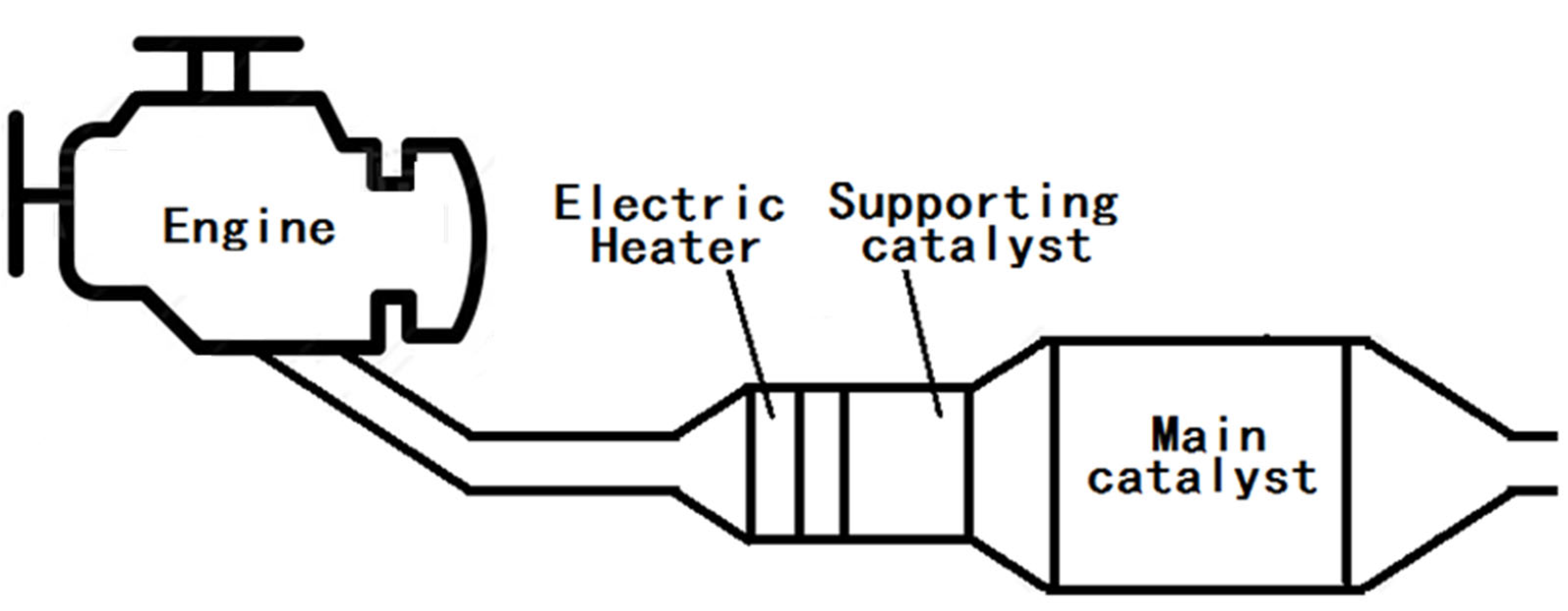
Figure 2.
Schematic of the experimental system for the diesel aftertreatment system, including the electric heater.
Figure 2.
Schematic of the experimental system for the diesel aftertreatment system, including the electric heater.
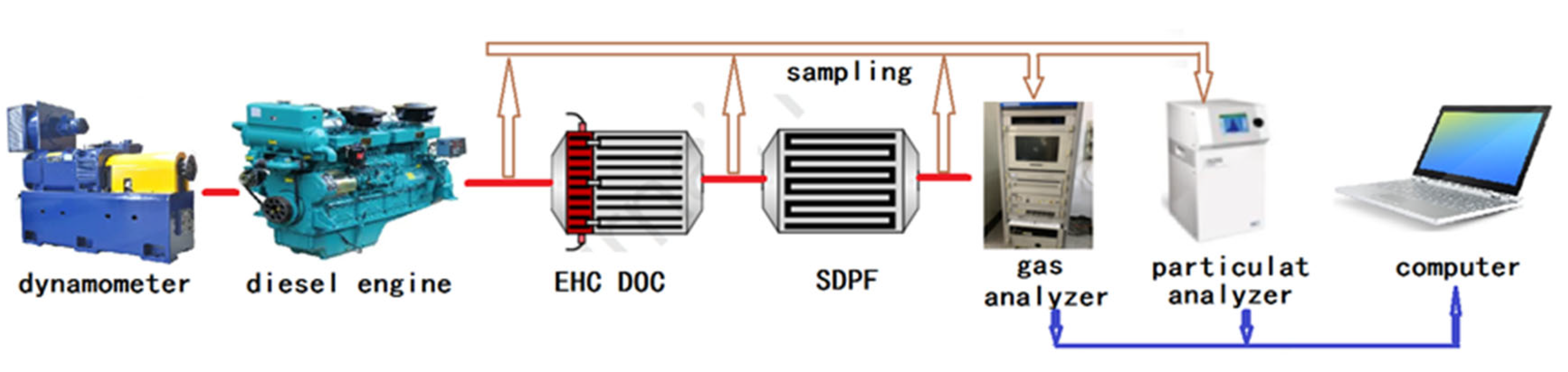
Figure 3.
The manufacturing method and structure of a rolled electric heater.
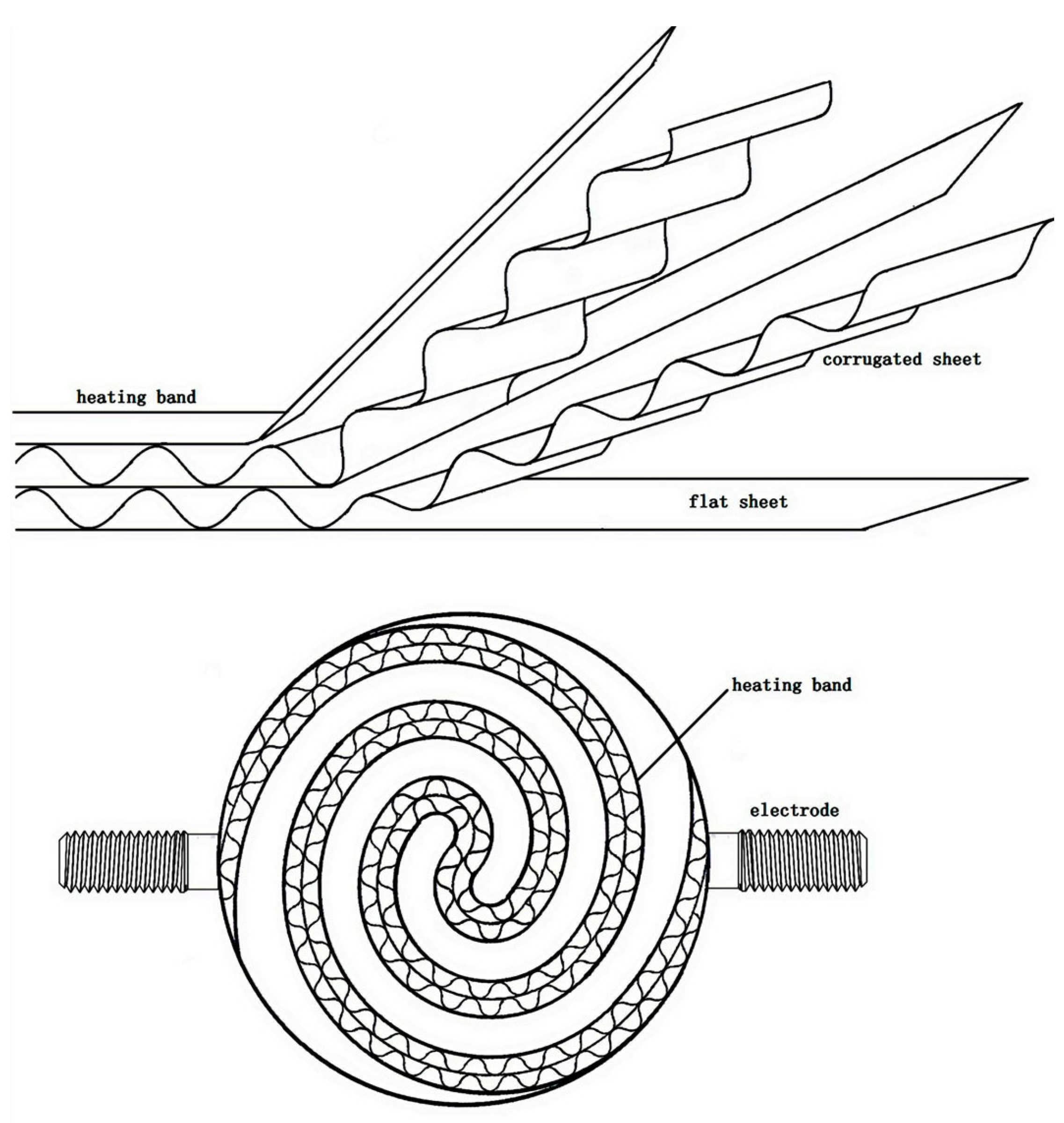
Figure 4.
The structure of an extruded electric heater.
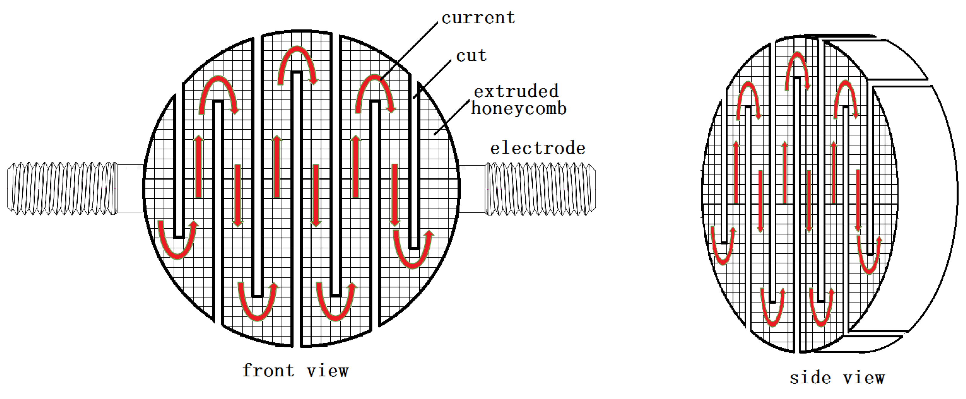
Figure 5.
A kind of AC electricity supply for an electric heater.
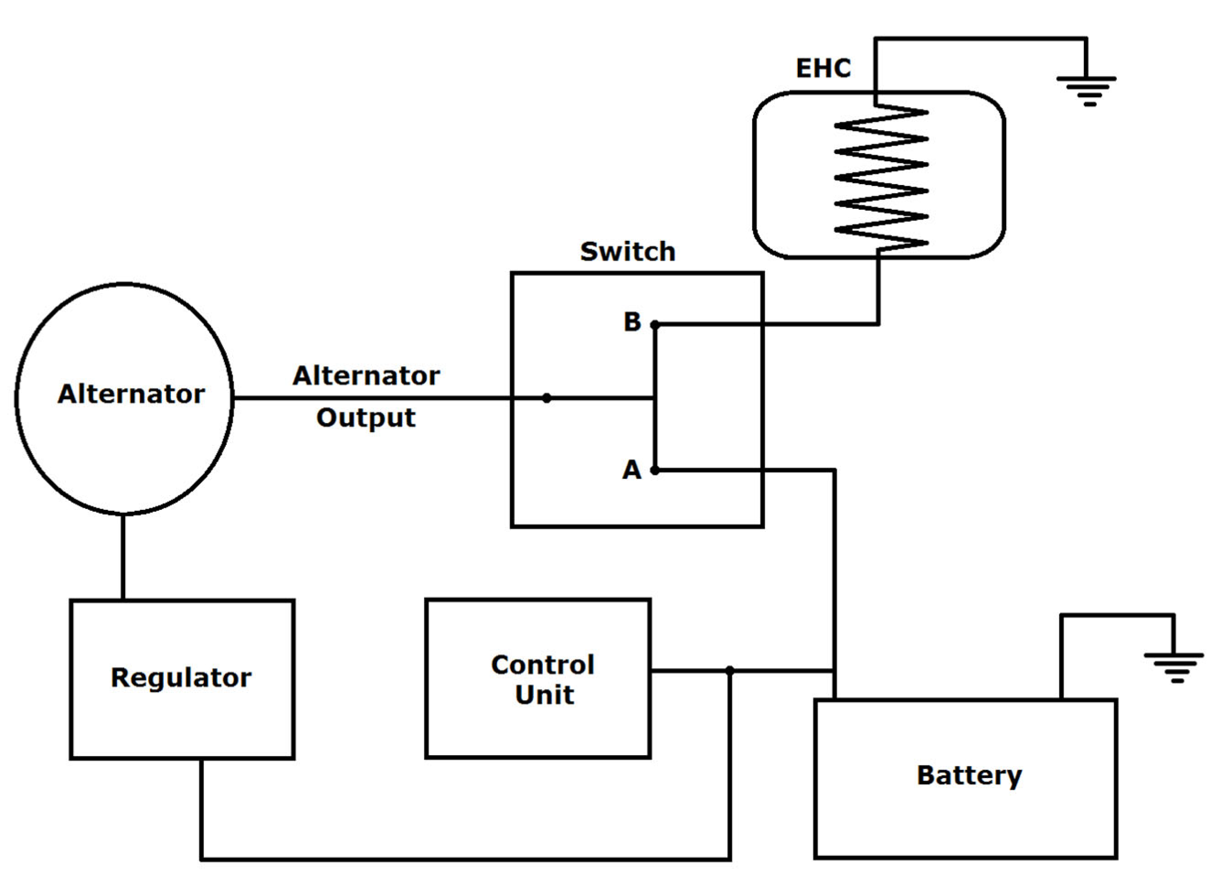
Figure 6.
Schematic of the waste heat recovery for diesel engine exhaust aftertreatment with electric heating power supply.
Figure 6.
Schematic of the waste heat recovery for diesel engine exhaust aftertreatment with electric heating power supply.
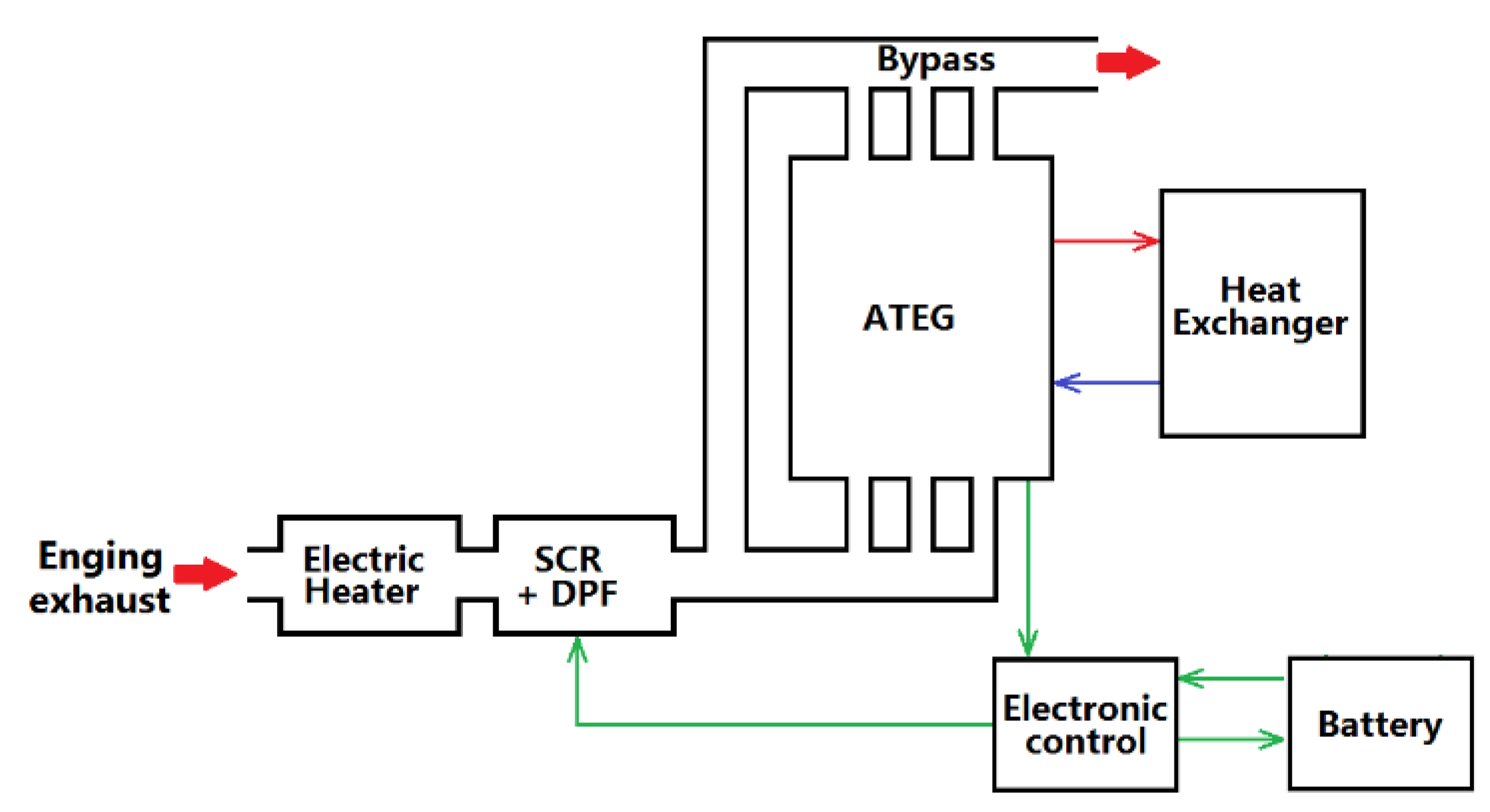
Disclaimer/Publisher’s Note: The statements, opinions and data contained in all publications are solely those of the individual author(s) and contributor(s) and not of MDPI and/or the editor(s). MDPI and/or the editor(s) disclaim responsibility for any injury to people or property resulting from any ideas, methods, instructions or products referred to in the content. |
© 2024 by the authors. Licensee MDPI, Basel, Switzerland. This article is an open access article distributed under the terms and conditions of the Creative Commons Attribution (CC BY) license (https://creativecommons.org/licenses/by/4.0/).
Share and Cite
MDPI and ACS Style
Li, K.; Xiao, B.; Wang, Y.; Jia, J.; Wu, X. Applications of Electric Heating Technology in Vehicle Exhaust Pollution Control. Processes 2024, 12, 298. https://doi.org/10.3390/pr12020298
AMA Style
Li K, Xiao B, Wang Y, Jia J, Wu X. Applications of Electric Heating Technology in Vehicle Exhaust Pollution Control. Processes. 2024; 12(2):298. https://doi.org/10.3390/pr12020298
Chicago/Turabian StyleLi, Kai, Bing Xiao, Yanjun Wang, Jianli Jia, and Xiaodong Wu. 2024. "Applications of Electric Heating Technology in Vehicle Exhaust Pollution Control" Processes 12, no. 2: 298. https://doi.org/10.3390/pr12020298
Note that from the first issue of 2016, this journal uses article numbers instead of page numbers. See further details here.