
Research Regarding the Dimensional Precision of Electrical Steel Strips Machined by Waterjet Cutting in Multilayer Packages


1
Department of Manufacturing Engineering, Transilvania University of Brasov, B-dul Eroilor 29, 500036 Brasov, Romania
2
Electroprecizia Electrical Motors Ltd., str. Electroprecizia nr.3, 505600 Săcele, Romania
3
Department of Automotive and Transport Engineering, Transilvania University of Brasov, B-dul Eroilor 29, 500036 Brasov, Romania
*
Author to whom correspondence should be addressed.
Processes 2023, 11(9), 2788; https://doi.org/10.3390/pr11092788
Submission received: 26 August 2023
/
Revised: 16 September 2023
/
Accepted: 16 September 2023
/
Published: 18 September 2023
Abstract
:Manufacturing parts made of thin steel in small batches is a challenging task in terms of reaching the proper balance between the productivity, the cost, and the dimensional precision. This paper presents the results of experimental research about manufacturing electrical steel thin parts using abrasive waterjet cutting. For a certain increase of productivity and a more efficient process, the parts were cut using multilayer packages of steel strips. The main objective was to analyze the influence of the number of layers on the dimensional precision of parts. Preliminary tests were performed, followed by a full factorial experiment using two independent parameters, the number of layers and the traverse speed. The parts were measured on a noncontact vision measurement machine and mathematical models were determined to predict the parts deviations depending on the independent parameters used. A practical validation of the models was performed. The main conclusion is that the number of layers has a certain influence on the accuracy of dimensions, but this influence can be predicted with a satisfactory level of confidence using mathematical models.
1. Introduction
Nowadays there is worldwide interest regarding environmentally friendly technologies, sustainability, and more efficient products, all with the aim of reducing pollution to the planet. This is also available for industrial products used in almost all types of industries, such as automotive, aerospace, or for machine tools, which are mainly responsible for implementing efficient production flow. The latter are used for product manufacturing, and these are large consumers of electricity because their construction needs one or several electrical motors, which usually drive the tool spindles or hydraulic/pneumatic pumps. Thus, the more efficient the electric motors are (low electricity consumption and high efficiency/torque/speed), the more efficient the production system will be.
The efficiency of an electrical motor is mainly given by two components and the interaction between them. These are the rotor and the stator of the motor. The stators and the rotors of electrical motors are basically composed of pure copper or copper alloys windings and steel laminations, which form the core of the rotor and the stator [1,2]. The prototyping process of the steel laminations is difficult. In the case of volume production, the steel laminations are manufactured by punching the lamination geometry on a mechanical press from steel sheet coils in an automated manner. Motor manufacturers use several dedicated electrical steels, such as M290-50A, M330-50A, M400-50A, or M700-50A, according to the DIN EN 10106 standard [3]. Each stator or rotor is composed of a few hundred steel laminations, which should be manufactured by the punching process. For small volumes of rotor or stator prototypes, the punching process is not quite suitable because the costs of the dies are very high. Thus, other cutting processes should replace the conventional punching process. Basically, there are four other methods that can be used in order to manufacture steel laminations for electric motors for prototyping purposes: on a CNC punching machine, by laser cutting, by a wire electrical discharge machining (WEDM), or by abrasive waterjet cutting (AWJM) [4].
In the case of the CNC punching machine, the main shortcoming is that the lamination shapes are usually complex ones with small details, which cannot be cut by any of the universal sets of punch shapes available for those CNC machines. Generally, the punching process affects also the magnetic properties of the material [5,6] but at a very small level; thus, the punching process with mechanical presses still remains the leading technology for electric motor laminated core production [7]. The laser cutting has a major disadvantage that by generating a thermal strain along the cutting edge, there is a negative influence on the magnetic properties of the material [5,6,8]. Regarding the WEDM process used for the steel laminations, even if it does not have an influence on the magnetic properties of the sheet steel [5,8,9], the cutting speed is very low and makes it the slowest manufacturing process in comparison with all other machining methods [7,9]. Another disadvantage of WEDM is that for the inside contours, a pre-drilling process is needed in order to obtain the hole to insert the copper wire used for cutting. Many researchers claim that abrasive waterjet cutting is the most suitable manufacturing process for steel laminations in small volume production needed for electric motor prototyping [8,10,11]. The abrasive waterjet process is a room temperature cutting process, and thus, it does not generate any local thermal stresses along the cutting edges so the material properties are not affected [12]. Even if the abrasive waterjet cutting can produce burs on the other side of the sheet and also oxidize the material [12], it is still the favorite manufacturing process in this case. The process is also faster than WEDM [10].
Waterjet cutting is used in many industrial or non-industrial fields in two technological variants: simple waterjet machining used only for soft materials or abrasive waterjet machining generally used for harder materials with different thicknesses [13]. In case of AWJM, abrasive particles mixed with a jet of water at very high pressure and speed are used in the machining process in order to cause the materials erosion [13,14]. Several types of abrasive particles are used: sand, aluminum oxide, silicon carbide, glass beads, etc. [13].
AWJM is a cold and non-contact machining process and has multiple advantages, such as thermal stress absence, no thermal deformations caused, high flexibility, high cutting speed, no tool sharpening needed, and no dedicated tools [13,15]. This process became very versatile over time and is also combined with conventional processes, such as turning [16,17,18], milling [19,20], drilling [21], grinding [22], polishing [23,24], or even used as micro-machining technology [17,25]. Overall, AWJM is a well-known process, which has been investigated in depth and presented by many researchers [13,14,17].
Much research has studied the main influence factors on the AWJM process. In the last decade, an in-depth review regarding the influence factors was published by Anu Kuttan et al. [13]. The review claims that those factors, which are in fact the process parameters, can be classified in four main categories as follow: cutting factors (traverse speed, stand-off distance, number of passes, and jet impingement angle), hydraulic factors (waterjet pressure and water orifice diameter), abrasive factors (abrasive particle shape, particle diameter/dimension, abrasive material hardness and abrasive mass flow rate), and mixing factors (focusing nozzle length and focusing nozzle diameter). Similar input influences are also assumed by other researchers, considering that those parameters affect the cutting performances (material removal rate and depth of cut), and the parts output results as the surface roughness, the kerf taper angle, the burr formation, striation marks, or even delamination in the case of laminated composite materials [14].
In order to highlight the parameter influences on different cutting part aspects, the majority of the research was usually conducted on thick materials with thicknesses between 5 mm and 100 mm [26,27]. After an overview regarding many studies in this field, Llanto at al [14] concluded that the most significant influence factors on the AWJM process performance are the traverse speed (most significant), waterjet pressure (second significant), abrasive mass flow rate (third significant), and standoff distance (fourth significant). The waterjet traverse speed has the most significant influence effect on the part’s output parameters [28,29]. Gnanavelbabu et al. [30] and Sasikumar et al. [31] conducted experiments on different materials and different thicknesses and concluded that using a low level of traverse speed leads to an improved kerf taper angle and surface roughness. Regarding waterjet pressure, the second major influence factor, most of the available studies proved that using a high level of waterjet pressure reduces the parts kerf angle and can also improve the surface roughness [31,32,33]. On the other side, several studies claim that a ultra-high pressure waterjet can even damage the part output parameter, especially for thinner sheets, because it increases the particles velocity, resulting in strong impact with the material [34]. Nevertheless, increasing water pressure also has a productivity advantage as the material removal rate and the depth of jet penetration are rising [14,33,35]. Marichamy et al. [36] concluded that at least for soft materials as brass machining through the AWJM process, a lower abrasive mass flow rate leads to better surface roughness. Meanwhile, another group of researchers claims that a high material remove rate but also a lower surface roughness are obtained for greater abrasive mass flow rate in the case of hard materials as titanium alloys [30] but also in the case of soft material as aluminum alloys [37]. Regarding the stand-off distance influence, as is expected, many studies proved that decreasing the distance between the nozzle and workpiece leads to an improved kerf width, surface roughness, and a bigger removal material rate [14,29,38].
The influence of the four factors presented above is usually higher when increasing the material thickness. Additionally, there are other less significant influence parameters, which are less studied in the literature. Their influences are smaller than the important ones, the traverse speed, waterjet pressure, abrasive mass flow rate, and standoff distance [14].
The current paper presents research on AWJM of thin sheets made of electrical steel, for manufacturing rotor and stator laminations in small batches, and for prototyping purposes. The sheets were processed in multiple layer packages, which were cut together to reach the proper balance between the productivity, the cost, and the dimensional precision. Extended experimental research was performed to determine mathematical models which predict the upper and lower deviations from the nominal dimensions depending on the traverse speed and the number of layers. The models were validated by experiments, and the level of confidence obtained was satisfactory.
2. Materials and Methods
Prototyping the electrical motor laminations for stators and rotors is a real challenge considering the aspects presented in the previous section. An example of stator and rotor laminations shape is presented in Figure 1. These laminations are made of thin metal sheet, whose details will be presented further in the paper.
In order to analyze the process of manufacturing of thin sheet metal parts in a multiple layers package using AWJM, experimental research was conducted with the purpose of assessing the geometrical deviations from the nominal dimension of the parts and evaluating their dependence on some of the main AWJM parameters. For this purpose, preliminary tests were done to obtain general conclusions regarding the cutting process. Further, the research followed a full factorial experimental plan using the factors and levels selected before the preliminary tests. At the end, a validation stage was also included.
2.1. Materials and Technological Setup
The material used for the experimental plan was the electrical steel M400-50A, according to the DIN EN 10106 standard and having the thickness of 0.5 mm [3]. This material is a common one used for motor laminations in the electrical motors manufacturing industries. The main mechanical properties and the chemical composition are presented in Table 1 [3].
The design of the part used during the experiments was made by analyzing the influence of the part’s geometry on its accuracy during AWJM. The most significant influence factor on AWJM is the traverse speed [14,17,18]. It is well known that the traverse speed is not constant along a complex contour of parts, such as the ones of the stator or rotor laminations. The speed depends on the contour curvature, which are constant along the straight lines and are decreasing along the curved ones. Taking into account this aspect, a simple geometry was designed in order to perform experimental trials, as presented in Figure 2. This design was adopted to obtain multiple outer dimensions, which are cut using a straight toolpath on AWJM, because the speed is constant along them. The measurements of the three dimensions, named OD1, OD2 and OD3, were taken between the lines marked in red (Figure 2).
The machine tool used for the tests was a MAXIEM 1530 abrasive waterjet machine from OMAX Company (OMAX Corporation, Kent, WA, USA). The fixing of the strips package was made using four simple C shape clamps, which are pressing on two lateral metal bars, as it is shown in Figure 3.
This fixing method is one of the simplest and is easy to implement for prototyping purposes but at the same time, could be unstable because it keeps together the sheet layers only on the lateral areas. The middle area of the sheet package is less tight, and thus, small gaps could appear between layers, affecting the cutting process and the parts dimensional accuracy.
2.2. Preliminary Tests
The preliminary tests aim to assess the maximum number of layers that can be cut at once using a certain range of values for the traverse speed. Three different layer packages (5 layers, 10 layers, and 15 layers in Figure 4) and three different traverse speeds (250 mm/min, 350 mm/min, and 450 mm/min) were tried. Only these two parameters were selected to be modified in the process because the traverse speed is the most significant influence factor on the AWJM process [14], and the number of layers cut together (package thickness) influences the productivity of the process. Both are also suitable to be easily modified by human operators in the production plant. Regarding the water pressure, it is recommended to use a high-pressure value for better cutting results, good surface roughness [14,32,34], and good productivity. Thus, the water pressure was maintained constant at the highest level of the AWJM machine, 350 MPa. Regarding another important parameter, the stand-off distance, it was maintained constant at 1.5 mm. The type of abrasive was GMA garnet 80 mesh, having the size of the particles between 0.18 mm and 0.30 mm. The abrasive rate used during the experiments was 300 g/min.
For an easier identification of each part after the experiments, a codification rule was used, exemplified for part configuration “P-F250-10-2” and with the following meaning: P (preliminary tests) or E (experimental plan) or V (validation tests), F250 is the feed rate/traverse speed value, 250 mm/min, 10 is the number of layers in the package, and 2 is the second layer from that package, ordered from top to bottom. This codification rule is available for all the experiments presented in this research.
According to the above considerations, all the configurations performed for the preliminary tests are presented in Table 2. The table also shows the limitations of some experiments.
According to Table 2, several trials were not completely succeeded, including the ones for the highest traverse speed value or for the 15 layers packages; thus, not all the planned experiments were performed. Figure 5 presents several parts machined in the preliminary test stage. The dimensions, OD1, OD2, and OD3, were measured for all the parts, using the digital calipers of a microscope, Mitutoyo MT-1005B (Mitutoyo, Kawasaki, Japan).
2.3. Preliminary Tests Results
The dimensional accuracy of a part is usually evaluated by the deviation from the nominal dimension. Deviations are differences between the minimum and maximum measured dimension, Dmin and Dmax, and the nominal dimension, Dnom (OD1, OD2 or OD3), according to equations [39]:
Deviations could be positive or negative. The total amount between the maximum deviation and the minimum deviation shows the tolerance spread field.
The results of the deviations for the parts machined during the preliminary trials are presented in Table 3.
Using the same microscope, the parts edges profile was analyzed in the area where the outer dimensions were measured. Several captures from the microscope edge analysis are presented in Figure 6. As a general rule, it was observed that the first part for all the packages has a relatively smooth edge profile, especially for small traverse speed values. When increasing the traverse speed or the number of layers, the edge profile becomes more and more nonlinear. When the profile edge is not smooth, it may also influence the outer dimension measurement, resulting in inaccurate OD values.
The following is an overview on how the AWJM of thin steel multilayer packages of strips was achieved after the preliminary tests. The main outcomes are:
- The process has limitations regarding the number of layers that can be cut together with the selected values of the traverse speed (Table 2).
- The maximum waterjet traverse speed was found, which can be used to obtain parts with a relatively suitable straight cut edge.
- The tolerance spread field obtained for each parameter configuration gave primary information regarding the dimension accuracy when using this machining method.
For the further full factorial experimental plan, the process parameters (traverse speed and layer packages) were selected based on the results obtained after the preliminary tests.
2.4. Extended Experimental Research
After the preliminary tests and a general overview about the process, further extended experimental research was conducted by implementing a full factorial experimental plan. The main goal of the experiments was to investigate the influence of the waterjet traverse speed and the number of layers of the packages on the dimensional accuracy of the outer dimensions of the parts. Consequently, by conducting more elaborate experimental research, the aim is to determine mathematical models which can be used to predict the dimensional precision that can be obtained using different values of the waterjet traverse speed and different numbers of layers of the package. For this purpose, the experiments were planned according to a well-known technique, the design of experiments (DOE). The Minitab 18 software tool was used to generate and manage those trials. The experimental plan factors and their levels were selected, and they are centralized in Table 4.
According to Table 4, two influence factors, each with three levels, were used in the DOE full factorial experimental plan design. Similar to the preliminary tests, the waterjet traverse speed and the package number of layers were kept as influence factors, but their levels were adjusted taking into account the results and the process limitations proved by those tests. The maximum value of the traverse speed was chosen to be 250 mm/min in order to ensure a complete cutting for the highest number of layers selected. Regarding the selected levels for the number of layers cut at once, three different packages were chosen: 4 layers, 7 layers, and 10 layers. The maximum number of layers per package was selected also according to the results proved in the preliminary tests when the 10-layer package was the one that was completely cut with the maximum traverse speed. Those factors and levels were implemented in DOE using Minitab, and a full factorial experimental plan was designed, according to Figure 7.
It is considered that replicas for those experiments are not needed because cutting each package will result in many parts at once, and more than that, for each part, three outer dimensions, OD1, OD2, and OD3, are measured.
The shapes of the parts are the same, which were used for the preliminary tests, as presented in Figure 5. The parts were manufactured according to the random order generated in Minitab, using the same abrasive waterjet machine, which was used for the preliminary tests, keeping the same values for the water pressure, the stand-off distance, and the waterjet head parameters.
Based on the planned design of experiment presented above, a total number of 63 parts were machined, and 189 measurements were taken for the outer dimensions. For this reason, it was considered that the results will have a great level of confidence.
3. Results and Discussion
3.1. Parts Deviation Measurements
For this stage, the measurements were taken using a high-performance 3D non-contact vision measurement machine from Mitutoyo, Quick Vision APEX (Mitutoyo, Japan), as presented in Figure 8. The machine is driven using the QVPAC software tool, which ensures an automated measurement. This measurement machine is able to ensure a stated accuracy by conforming to ISO 10360-7 [40]; thus, it guarantees the correctness of the measured values.
All the measurements were centralized on an Excel worksheet for easier data management. For each experimental configuration, two values were extracted and used as responses in the DOE method, the minimum deviation (Devmin) and the maximum deviation (Devmax). As an example, the values measured for the parts manufactured using experimental configuration E-F150-4-1…4 are presented in Table 5.
The experimental plan, including the minimum and maximum deviations for all trials, is presented in Figure 9.
3.2. Mathematical Models Used for Parts Deviation Prediction
Usually, when thin sheet parts are manufactured or prototyped using AWJM and processed as a multilayer package, the major interest is to predict the geometric tolerances obtained by cutting those parts. The prediction can be assessed with graphical representations or mathematical models. For this purpose, the results of the experimental plan were analyzed using the fit regression model available in Minitab. This regression analysis is one of the most popular methods, which describes the relationship between predictors (factors) and one single response. Thus, this model was used in order to highlight the factors’ influences upon each response from the experimental plan, Devmin and Devmax. Therefore, after regression analysis was applied using the same factors (traverse speed and number of layers per package) but two different responses, the following mathematical models for Devmin and Devmax predictions were obtained:
These mathematical models can be used to predict minimum and maximum deviations for parts manufactured from thin sheets for different values of the waterjet traverse speed and different number of layers cut at once using the multilayer package method.
The regression analysis confidence is characterized by the statistical parameters called “coefficient of correlation R2” and “standard deviation S” which are presented in Table 6.
Small values for standard deviation S mean that the obtained mathematical model succeeds in a proper response description. There is also a similar meaning for high values of the coefficient of correlation R2, the models being more and more accurate as the term R2 increases towards 100%. For both statistical parameters, the values are satisfactory.
3.3. Practical Validation of Mathematical Models
In the case of Devmin, the R2 coefficient has a smaller value of around 91%, this being one reason why it was decided to implement a validation phase. The validation is also helpful in order to confirm the regression analysis level of confidence and to confirm that the mathematical models obtained through the statistical analysis can certainly be used as prediction models for AWJM cutting of thin sheet metal parts with the multilayer package method.
Thus, two more experimental configurations were machined with the same setup used for the previous experiments. For these two validation trials, there were different process parameter (water jet traverse speed and package number of layers) values used and placed inside the range of the ones used in the full factorial experimental plan. These values, together with the calculated values of the predicted deviations using the mathematical models (3) and (4), are presented in Table 7. Each configuration name is preceded by the symbol “V” (validation).
Both sets of values for the outer dimensions, calculated and measured, were compared using the graphical representation presented in Figure 10. The analysis of these values shows that the predicted deviations are close to the measured ones on the machined parts for almost all the compared values. If for the V-F175-5-1…5 experimental configuration, the difference between the measured and the predicted values do not exceed 0.004 mm, and for the V-F225-8-1…8 experimental set, the values for minimum deviations are matching quite precise (0.005 mm), but there is a difference for maximum deviation of 0.021 mm.
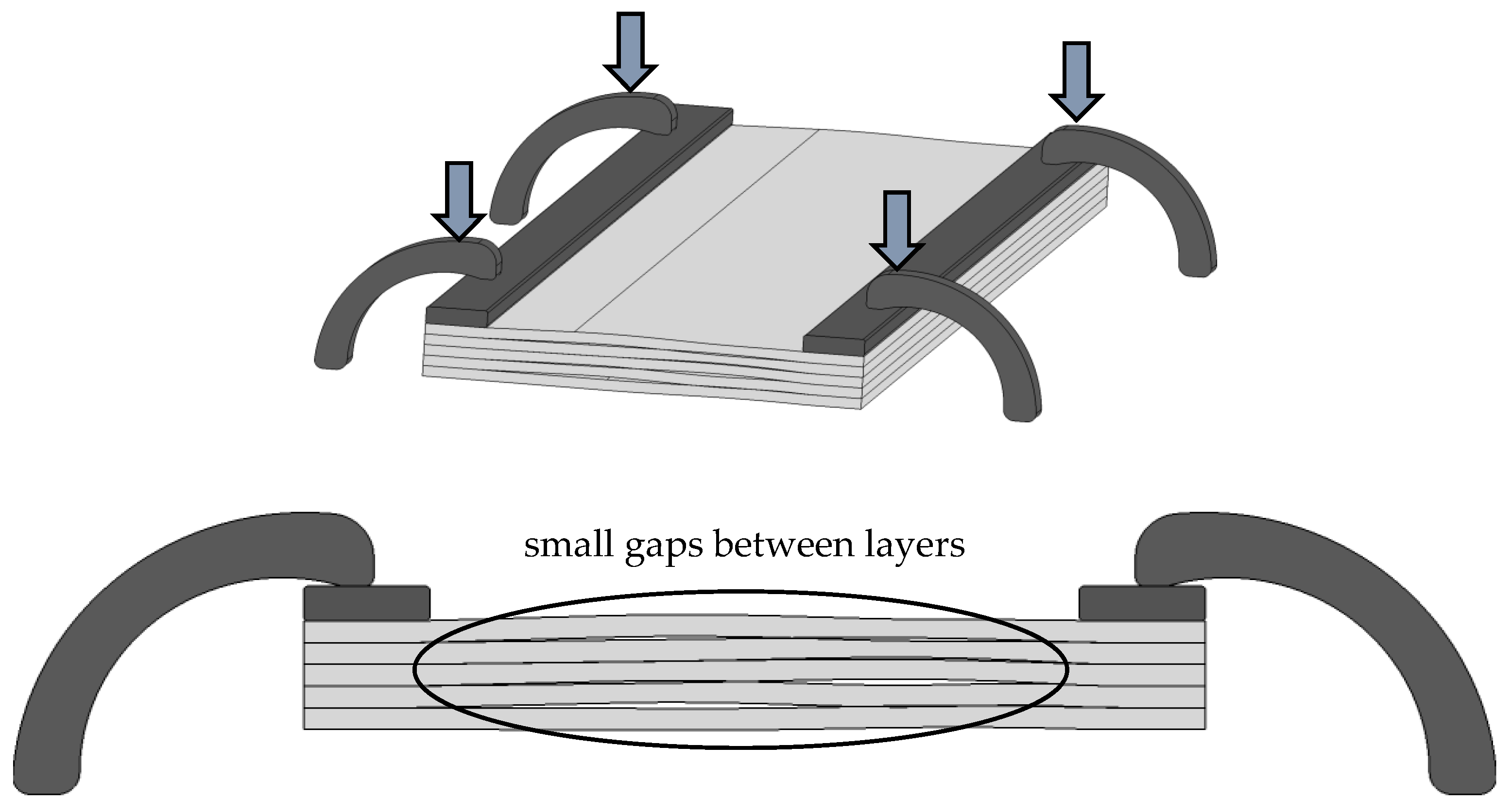
The difference between the predicted values and the measured ones on the parts is provided by analyzing the fixture system used. The sheet strips, especially the ones obtained from coils, have their own flatness deviation, and when they are layered in a package and fixed together only on the lateral areas, small gaps could remain between the layers in the cutting area (Figure 11).
In the cases of cutting multilayer packages when the sheets are completely separated, the behavior of the material is different compared to the AWJM cutting of multilayer composite structures when the layers are welded or glued together [41]. The fixing method on the machine tool is very important because it is the single method to keep the layers as closed as possible without gaps between layers. The fixing method can be improved by implementing a more rigid contoured fixing plate between the clamps and the sheet package, but this will increase the manufacturing time and costs. This gap phenomenon can bring differences between real and predicted deviations and should be treated carefully.
4. Conclusions
The paper presents research concerning the dimensional accuracy for parts manufactured from thin electrical sheet strips by abrasive waterjet machining in a multilayer package. Influence factors for AWJM were analyzed and selected based on the literature review available in this field. The research was divided into three stages: preliminary tests, extended full factorial experimental plan, and validation tests. An overview and the process limitations were assessed by the initial preliminary tests. Extended experimental research was further conducted based on the results obtained in the initial tests. Regression analysis was applied on the deviations results of the extended research, and mathematical models were obtained for minimum deviations (Devmin) and maximum deviations (Devmax). The possibility of using these models to predict the parts deviations for different number of layers and various traverse speed values, was proved by the validation stage. The key conclusions of this research are the following:
- Waterjet machining is a proper process, which can be successfully used to manufacture thin sheet metal parts for electrical motor laminations prototyping or for small volume production, maintaining the dimensional precision in a range suitable for such type of parts.
- Initial experimental trials were performed in order to identify the process limitations regarding the most important influence factors, waterjet traverse speed and number of layers per package to be cut at once. These two factors are also the easiest to be modified by operators in the production plants. According to the preliminary tests, the maximum number of layers per package succeeded in being cut using a maximum traverse speed of 250 mm/min was ten layers.
- Extended experimental research, based on a full factorial plan, was conducted to study the process parameters influence (waterjet traverse speed and number of layers per package) on part accuracy. The maximum and the minimum deviations from the nominal dimensions were the research responses and were statistically processes by regression analysis in order to obtain mathematical models for dimensional accuracy prediction in the case of cutting multilayer packages when the sheets are completely separated and not glued or welded together.
- The mathematical model confidence was confirmed by additional experiments in a validation stage. The differences between the deviations calculated by mathematical models and the real deviations measured on the machined parts were in good agreement.
The machining setup presented in the paper is easy to implement in the case of prototyping or small volume production of electrical motors lamination and ensure positive results regarding the parts accuracy and productivity. The paper opens future research opportunities, such as studies using different materials or sheet thicknesses, studies on the entire contour for complex parts, different variant for package fixture or even developing a modular fixture design dedicated for sheet package cutting on AWJM.
Author Contributions
Conceptualization, D.N., A.C.F., S.Z. and G.O.; methodology, D.N., A.C.F. and G.O.; validation, D.N. and A.C.F.; formal analysis, D.N.; investigation, D.N., A.C.F. and G.O.; resources, D.N., A.C.F. and S.Z.; data curation, D.N.; writing—original draft preparation, D.N.; writing—review and editing, D.N., A.C.F. and G.O.; visualization, D.N., A.C.F., S.Z. and G.O.; supervision, G.O.; project administration, G.O. All authors have read and agreed to the published version of the manuscript.
Funding
This research was funded by Ministerul Cercetării, Inovării și Digitalizării prin Programul Operational Competitivitate, Romania (Ministry of Research, Innovation, and Digitalization through the Operational Program Competitivity, Romania) project “Cresterea competitivitatii Electroprecizia Electrical Motors prin dezvoltarea in parteneriat cu Universitatea Transilvania a unei noi familii de motoare electrice, cu eficienta energetica de clasa superpremium (IE4) (Increasing the competitiveness of Electroprecizia Electrical Motors by developing in partnership with Transilvania University a new electrical motors family with super-premium energetical class (IE4))/121228/POC/163/1/3” (translation from Romanian). The APC was funded by Transilvania University of Brasov.
Institutional Review Board Statement
Not applicable.
Informed Consent Statement
Not applicable.
Data Availability Statement
Data sharing is not applicable.
Acknowledgments
We acknowledge Mitutoyo Romania SRL for supporting the parts measurement.
Conflicts of Interest
The authors declare no conflict of interest.
References
- Ion, C.P.; Calin, M.D.; Peter, I. Design of a 3 kW PMSM with Super Premium Efficiency. Energies 2023, 16, 498. [Google Scholar] [CrossRef]
- Cezário, C.A.; Verardi, M.; Borges, S.S.; Silva, J.C.; Oliveira, A.A.M. Transient Thermal Analysis of an Induction Electric Motor. In Proceedings of the 18th International Congress of Mechanical Engineering, Ouro Preto, Brazil, 6–11 November 2005; pp. 1–8. [Google Scholar]
- DIN EN 10106:2015; Cold Rolled Non-Oriented Electrical Steel Strip and Sheet Delivered in the Fully Processed State. iTeh, Inc.: Newark, DE, USA, 2015.
- Mihail, L.; Filip, A.; Mija, A. Researches on the geometrical and dimensional accuracy for complex thin parts made of electrical steel by abrasive waterjet machining. IOP Conf. Ser. Mater. Sci. Eng. 2022, 1268, 012008. [Google Scholar] [CrossRef]
- Naumoski, H.; Riedmüller, B.; Minkow, A.; Herr, U. Investigation of the influence of different cutting procedures on the global and local magnetic properties of non-oriented electrical steel. J. Magn. Magn. Mater. 2015, 392, 126–133. [Google Scholar] [CrossRef]
- Paltanea, V.M.; Paltanea, G.; Gavrila, H.; Peter, I. The influence of punching and laser cutting technologies on the magnetic properties of non-oriented silicon iron steels. In Proceedings of the 2014 International Symposium on Fundamentals of Electrical Engineering (ISFEE), Bucharest, Romania, 28–29 November 2014; Volume 2015, pp. 3–6. [Google Scholar] [CrossRef]
- Paltanea, G.; Manescu, V.; Nemoianu, I.V.; Gavrilǎ, H.; Andrei, P.C. Influence of cutting technologies on the magnetic anisotropy of grain oriented electrical steel. In Proceedings of the 2017 Electric Vehicles International Conference (EV), Bucharest, Romania, 5–6 October 2017; Volume 2017, pp. 1–4. [Google Scholar] [CrossRef]
- Shi, W.; Liu, J.; Li, C. Effect of cutting techniques on the structure and magnetic properties of a high-grade non-oriented electrical steel. J. Wuhan Univ. Technol. Mater. Sci. Ed. 2014, 29, 1246–1251. [Google Scholar] [CrossRef]
- Hofmann, M.; Naumoski, H.; Herr, U.; Herzog, H.G. Magnetic Properties of Electrical Steel Sheets in Respect of Cutting: Micromagnetic Analysis and Macromagnetic Modeling. IEEE Trans. Magn. 2016, 52. [Google Scholar] [CrossRef]
- Schoppa, A.; Louis, H.; Pude, F.; Von Rad, C. Influence of abrasive waterjet cutting on the magnetic properties of non-oriented electrical steels. J. Magn. Magn. Mater. 2003, 254–255, 370–372. [Google Scholar] [CrossRef]
- Sundaria, R.; Hemeida, A.; Arkkio, A.; Daem, A.; Sergeant, P.; Belahcen, A. Effect of Different Cutting Techniques on Magnetic Properties of Grain Oriented Steel Sheets and Axial Flux Machines. In Proceedings of the IECON 2019—45th Annual Conference of the IEEE Industrial Electronics Society, Lisbon, Portugal, 14–17 October 2019. [Google Scholar] [CrossRef]
- Paltanea, V.-M.; Paltanea, G.; Gavrila, H. Some important effects of the water jet and laser cutting methods on the magnetic properties of the non-oriented silicon iron sheets. In Proceedings of the 2015 9th International Symposium on Advanced Topics in Electrical Engineering (ATEE), Bucharest, Romania, 7–9 May 2015. [Google Scholar] [CrossRef]
- Anu Kuttan, A.; Rajesh, R.; Dev Anand, M. Abrasive water jet machining techniques and parameters: A state of the art, open issue challenges and research directions. J. Braz. Soc. Mech. Sci. Eng. 2021, 43, 220. [Google Scholar] [CrossRef]
- Llanto, J.M.; Tolouei-Rad, M.; Vafadar, A.; Aamir, M. Recent Progress Trend on Abrasive Waterjet Cutting of Metallic Materials: A Review. Appl. Sci. 2021, 11, 3344. [Google Scholar] [CrossRef]
- Cui, D.; Li, H.; He, J.; Wang, Q.; Lu, C.; Hu, H.; Cheng, X.; Wang, C. Applications of Water Jet Cutting Technology in Agricultural Engineering: A Review. Appl. Sci. 2022, 12, 8988. [Google Scholar] [CrossRef]
- Zohourkari, I.; Zohoor, M.; Annoni, M. Investigation of the effects of machining parameters on material removal rate in abrasive waterjet turning. Adv. Mech. Eng. 2014, 6, 24203. [Google Scholar] [CrossRef]
- Gembalová, L.; Hlaváč, L.M.; Spadło, S.; Geryk, V.; Oros, L. Notes on the Abrasive Water Jet (AWJ) Machining. Materials 2021, 14, 7032. [Google Scholar] [CrossRef] [PubMed]
- Štefek, A.; Raška, J.; Hlaváč, L.M.; Spadło, S. Investigation of Significant Parameters during Abrasive Waterjet Turning. Materials 2021, 14, 4389. [Google Scholar] [CrossRef] [PubMed]
- Cenac, F.; Zitoune, R.; Collombet, F.; Deleris, M. Abrasive water-jet milling of aeronautic aluminum 2024-T3. Proc. Inst. Mech. Eng. Part L J. Mater. Des. Appl. 2015, 229, 29–37. [Google Scholar] [CrossRef]
- Yuan, Y.; Chen, J.; Gao, H.; Wang, X. An investigation into the abrasive waterjet milling circular pocket on titanium alloy. Int. J. Adv. Manuf. Technol. 2020, 107, 4503–4515. [Google Scholar] [CrossRef]
- ShivajiRao, M.; Satyanarayana, S. Abrasive water jet drilling of float glass and characterization of hole profile. Glas. Struct. Eng. 2020, 5, 155–169. [Google Scholar] [CrossRef]
- Liang, Z.; Xie, B.; Liao, S.; Zhou, J. Concentration degree prediction of AWJ grinding effectiveness based on turbulence characteristics and the improved ANFIS. Int. J. Adv. Manuf. Technol. 2015, 80, 887–905. [Google Scholar] [CrossRef]
- Loc, P.H.; Shiou, F.J. Abrasive water jet polishing on Zr-based bulk metallic glass. AMR 2012, 579, 211–218. [Google Scholar] [CrossRef]
- Zhang, Z.; Song, C.; Shi, F.; Tie, G.; Zhang, W.; Wang, B.; Tian, Y.; Hou, Z. Theoretical Modeling Method for Material Removal Characteristics of Abrasive Water Jet Polishing under Rotating Oblique Incidence. Micromachines 2022, 13, 1690. [Google Scholar] [CrossRef]
- Haghbin, N.; Spelt, J.K.; Papini, M. Abrasive waterjet micro-machining of channels in metals: Model to predict high aspect-ratio channel profiles for submerged and unsubmerged machining. J. Mater. Process Technol. 2015, 222, 399–409. [Google Scholar] [CrossRef]
- Selvan, M.C.; Raju, D.N. Analysis of Surface Roughness in Abrasive Waterjet Cutting of Cast Iron. Int. J. Sci. Environ. Technol. 2012, 1, 174–182. [Google Scholar]
- Wang, S.; Zhang, S.; Wu, Y.; Yang, F. Exploring kerf cut by abrasive waterjet. Int. J. Adv. Manuf. Technol. 2017, 93, 2013–2020. [Google Scholar] [CrossRef]
- Ishfaq, K.; Mufti, N.A.; Ahmed, N.; Pervaiz, S. Abrasive waterjet cutting of cladded material: Kerf taper and MRR analysis. Mater. Manuf. Process 2019, 34, 544–553. [Google Scholar] [CrossRef]
- Babu, M.N.; Muthukrishnan, N. Exploration on Kerf-angle and Surface Roughness in Abrasive Waterjet Machining using Response Surface Method. J. Inst. Eng. India Ser. C 2018, 99, 645–656. [Google Scholar] [CrossRef]
- Gnanavelbabu, A.; Saravanan, P.; Rajkumar, K.; Karthikeyan, S. Experimental Investigations on Multiple Responses in Abrasive Waterjet Machining of Ti-6Al-4V Alloy. Mater. Today Proc. 2018, 5, 13413–13421. [Google Scholar] [CrossRef]
- Sasikumar, K.; Arulshri, K.; Ponappa, K.; Uthayakumar, M. A study on kerf characteristics of hybrid aluminium 7075 metal matrix composites machined using abrasive water jet machining technology. Proc. Inst. Mech. Eng. Part B J. Eng. Manuf. 2018, 232, 690–704. [Google Scholar] [CrossRef]
- Babu, M.N.; Muthukrishnan, N. Investigation on Surface Roughness in Abrasive Water-Jet Machining by the Response Surface Method. Mater. Manuf. Process 2014, 29, 1422–1428. [Google Scholar] [CrossRef]
- Pashmforoush, F.; Hassanpour Bab-ajan, A.; Beyraghi Baranlou, R. Experimental Study of Geometric Tolerances and Surface Roughness in Abrasive Water Jet Machining Process of Hardox 400 Steel. Modares Mech. Eng. 2020, 20, 953–961. [Google Scholar]
- Akkurt, A.; Kulekci, M.K.; Seker, U.; Ercan, F. Effect of feed rate on surface roughness in abrasive waterjet cutting applications. J. Mater. Process Technol. 2004, 147, 389–396. [Google Scholar] [CrossRef]
- Adam Khan, M.; Gupta, K. Machinability Studies on Abrasive Water Jet Machining of Low Alloy Steel for Different Thickness. IOP Conf. Ser. Mater. Sci. Eng. 2020, 709, 44099. [Google Scholar] [CrossRef]
- Marichamy, S.; Ravichandran, M.; Stalin, B.; Sridhar Babu, B. Optimization of abrasive water jet machining parameters for α-β brass using Taguchi methodology. FME Trans. 2019, 47, 116–121. [Google Scholar] [CrossRef]
- Shibin, R.; Anandakrishnan, V.; Sathish, S.; Mallemala Sujana, V. Investigation on the abrasive water jet machinability of AA2014 using SiC as abrasive. Mater. Today Proc. 2020, 21, 519–522. [Google Scholar] [CrossRef]
- Kechagias, J.; Petropoulos, G.; Vaxevanidis, N. Application of Taguchi Design for Quality Characterization of Abrasive Water Jet Machining of TRIP Sheet Steels. Int. J. Adv. Manuf. Technol. 2012, 62, 635–643. [Google Scholar] [CrossRef]
- Henzold, G. Geometrical Dimensioning and Tolerancing for Design, Manufacturing and Inspection: A Handbook for Geometrical Product Specification using ISO and ASME Standards, 2nd ed.; Butterworth-Heinemann: Oxford, UK, 2006. [Google Scholar] [CrossRef]
- Mitutoyo—Quick Vision APEX. Available online: https://WwwMitutoyoCom/Quick-Vision-Apex-Generation-E/ (accessed on 3 July 2023).
- Ishfaq, K.; Ahmad, N.; Ahmad Mufti, N.; Saleem, M.Q.; M. Al-Ahmari, A. Abrasive Waterjet Cutting of Clad Composite for Achieving Minimal Cut Quality Difference Between Constituent Layers. Metals 2019, 9, 754. [Google Scholar] [CrossRef]
Figure 1.
Example of stator and rotor lamination shapes.
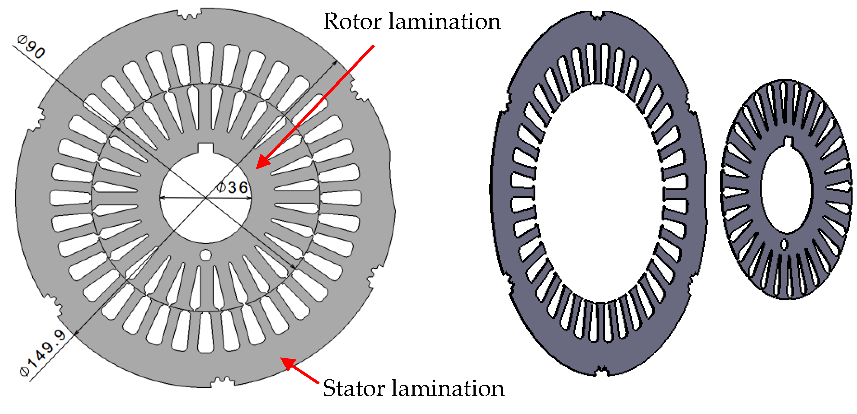
Figure 2.
Part shape and dimensions for experimental research, in mm.
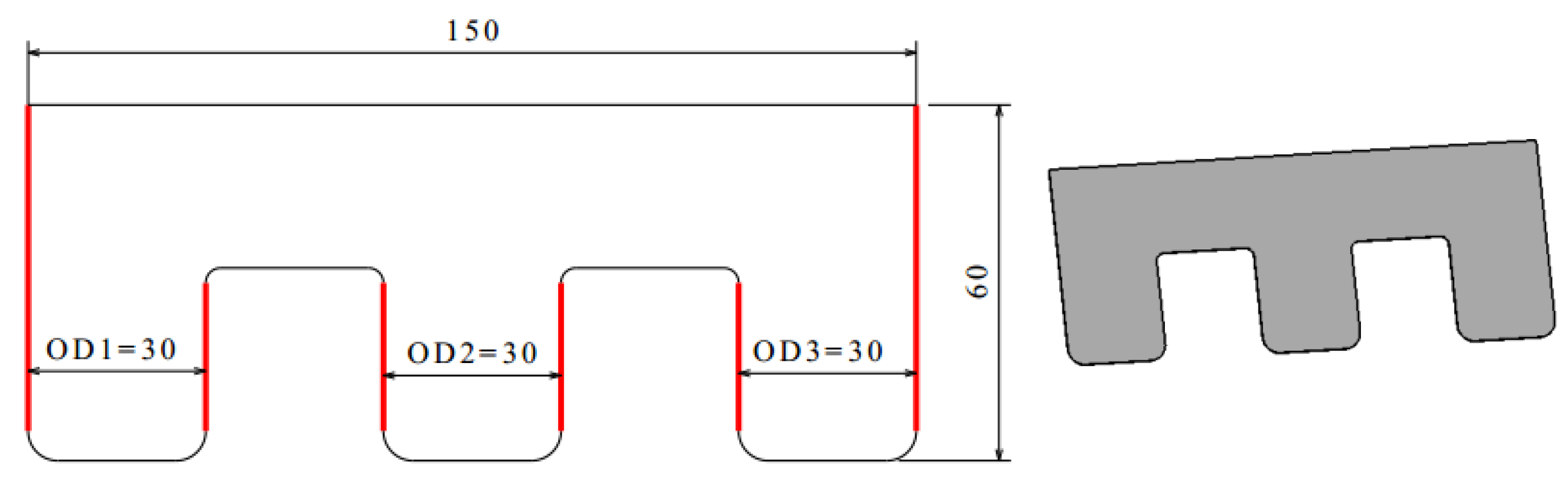
Figure 3.
Machine and fixing setup for sheets package.

Figure 4.
Layers package and nomenclature.

Figure 5.
Preliminary tests: (a) sample parts from preliminary tests; (b) measurements on Mitutoyo MT-1005B microscope.
Figure 5.
Preliminary tests: (a) sample parts from preliminary tests; (b) measurements on Mitutoyo MT-1005B microscope.
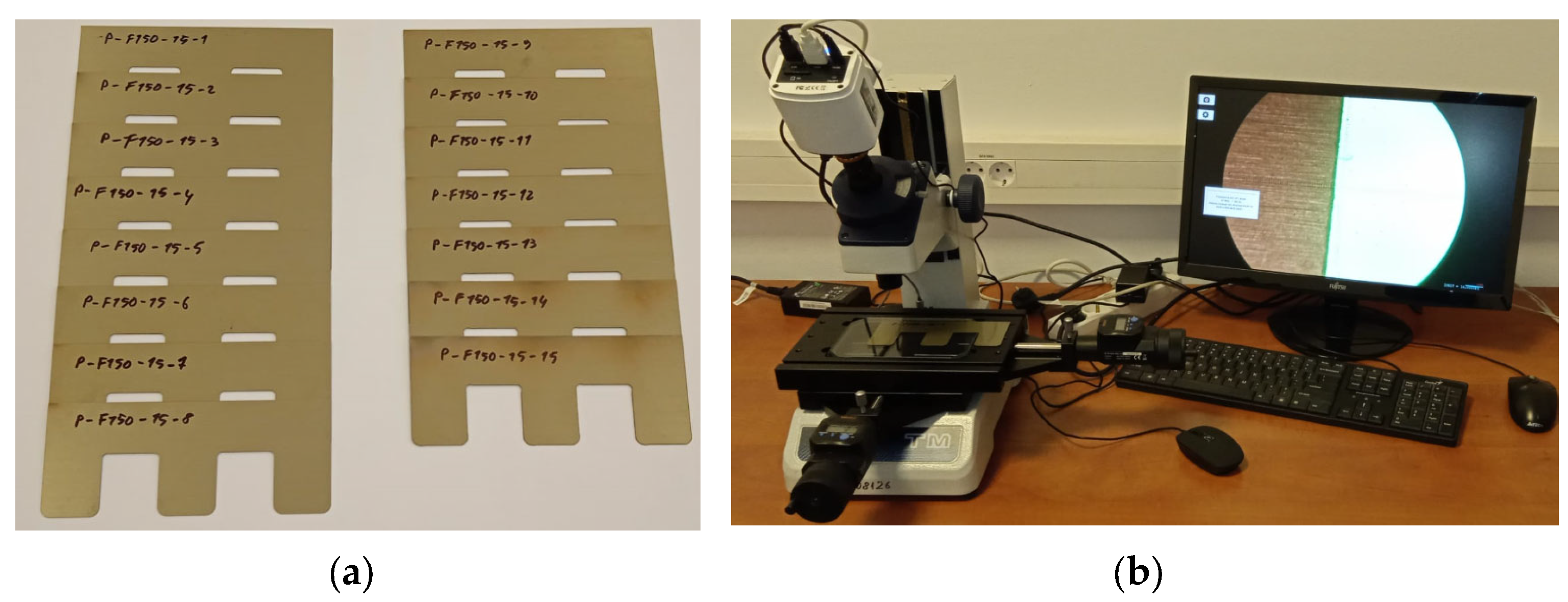
Figure 6.
Edge profiles for parts machined during preliminary tests: (a) P-F150-15-1; (b) P-F250-5-1; (c) P-F450-5-1; (d) P-F250-5-5; (e) P-F350-5-5; (f) P-F450-5-5; (g) P-F250-10-10; (h) P-F350-10-8; (i) P-F250-15-11.
Figure 6.
Edge profiles for parts machined during preliminary tests: (a) P-F150-15-1; (b) P-F250-5-1; (c) P-F450-5-1; (d) P-F250-5-5; (e) P-F350-5-5; (f) P-F450-5-5; (g) P-F250-10-10; (h) P-F350-10-8; (i) P-F250-15-11.
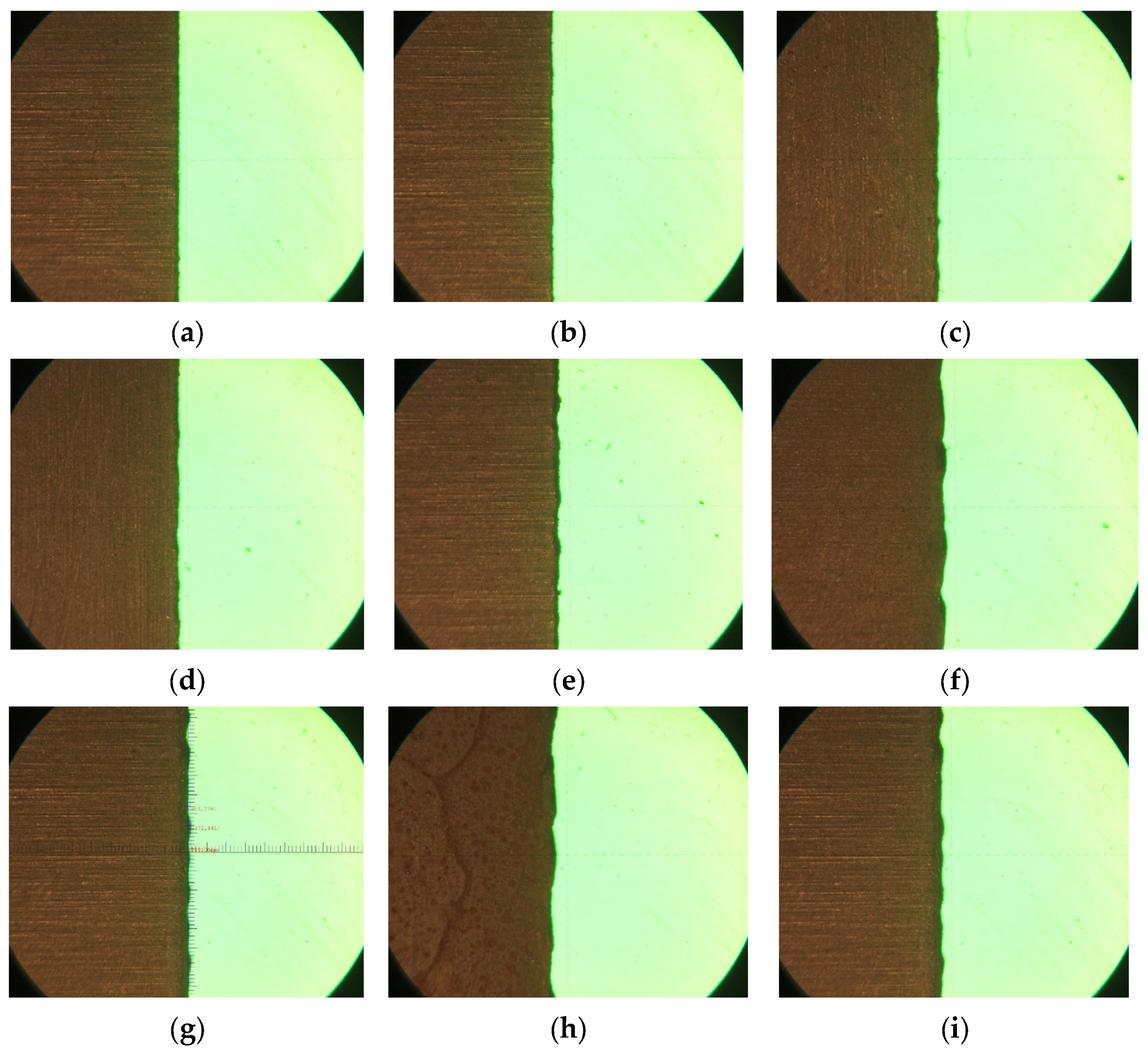
Figure 7.
Capture for the full factorial experimental plan designed using Minitab.

Figure 8.
Mitutoyo Quick Vision APEX machine in the measurement process.
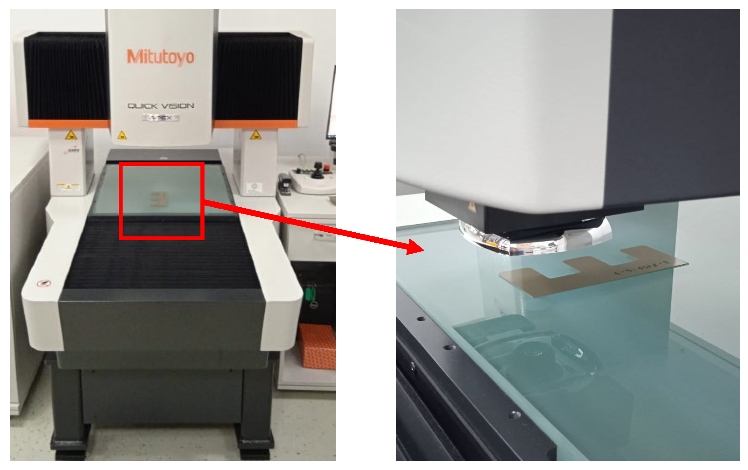
Figure 9.
Capture for the experimental plan and values for minimum and maximum deviations.

Figure 10.
Graphical comparison for calculated and predicted deviations: (a) minimum deviation comparison; (b) maximum deviation comparison.
Figure 10.
Graphical comparison for calculated and predicted deviations: (a) minimum deviation comparison; (b) maximum deviation comparison.
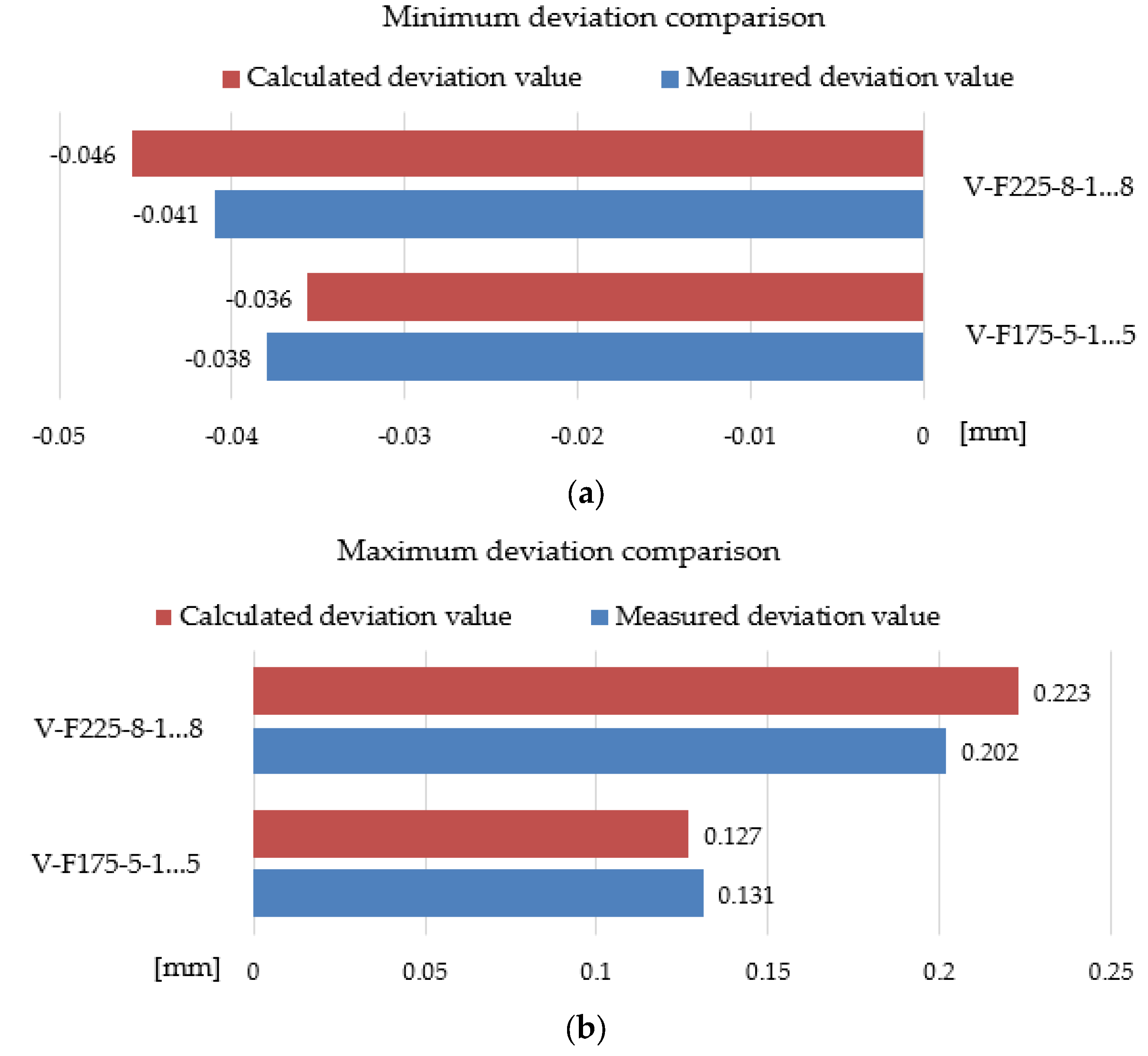
Figure 11.
Illustration of small gaps that can appear between layers.

Table 1.
Main mechanical properties and the chemical composition of M400-50A material [3].
Table 1.
Main mechanical properties and the chemical composition of M400-50A material [3].
| Main Mechanical Properties of M400-50A Material | ||||
|---|---|---|---|---|
| Density (kg/dm3) | Yield Strength (N/mm2) | Tensile Strength (N/mm2) | Young’s Modulus (N/mm2) | Hardess (Vickers) |
| 7.7 | 305 | 445 | 210,000 | 150 |
| Main elements for chemical composition of M400-50A material | ||||
| Si (%) | Mn (%) | P (%) | S (%) | Al (%) |
| 1.5–1.9 | 0.4–0.6 | 0.09–0.12 | max. 0.01 | 0.3–0.45 |
Table 2.
Preliminary test configurations and limitations.
| Experiments Performed for Preliminary Tests | ||||
|---|---|---|---|---|
| Part Code | Traverse Speed (mm/min) | Package Number of Layers | Succeeded Cut | Maximum Layers Cut Completed |
| P-F250-5-1…5 | 250 | 5 | Yes | All |
| P-F350-5-1…5 | 350 | 5 | Yes | All |
| P-F450-5-1…5 | 450 | 5 | Yes | All |
| P-F250-10-1…10 | 250 | 10 | Yes | All |
| P-F350-10-1…10 | 350 | 10 | No | max 8 layers of 10 |
| P-F450-10-1…10 | 450 | 10 | Not performed | - |
| P-F250-15-1…15 | 250 | 15 | No | max 11 layers of 15 |
| P-F350-15-1…15 | 350 | 15 | Not performed | - |
| P-F450-15-1…15 | 450 | 15 | Not performed | - |
| P-F150-15-1…15 | 150 | 15 | Yes | All |
Table 3.
Measurement results for preliminary tests.
| Part Code | Minimum Deviations Devmin (mm) | Maximum Deviations Devmax (mm) | Tolerance Spread Field (mm) |
|---|---|---|---|
| P-F250-5-1…5 | −0.35 | −0.12 | 0.23 |
| P-F350-5-1…5 | −0.27 | −0.09 | 0.18 |
| P-F450-5-1…5 | −0.27 | 0.01 | 0.28 |
| P-F250-10-1…10 | −0.32 | −0.02 | 0.30 |
| P-F350-10-1…10 | −0.28 | 0.14 | 0.42 |
| P-F250-15-1…15 | −0.32 | 0.11 | 0.43 |
| P-F150-15-1…15 | −0.33 | 0.02 | 0.35 |
Table 4.
Design of experiments factors and levels.
| Factor Description | Factor Name | Measurement Unit | Number of Levels | Level Values | Code of the Trial Configuration |
|---|---|---|---|---|---|
| Waterjet feed rate/traverse speed | Ts | mm/min | 3 | 150 | E-F150-4-1…4 |
| 200 | E-F200-4-1…4 | ||||
| 250 | E-F250-4-1…4 | ||||
| Layer package | Nl | number of layers | 3 | 4 | E-F150-7-1…7 |
| 7 | E-F200-7-1…7 | ||||
| 10 | E-F250-7-1…7 | ||||
| E-F150-10-1…10 | |||||
| E-F200-10-1…10 | |||||
| E-F250-10-1…10 |
Table 5.
Measurements obtained for E-F150-4-1…4 experimental configuration.
| Experimental Configuration | Nominal Dimension (mm) | OD1 (mm) | Dev OD1 (mm) | OD2 (mm) | Dev OD2 (mm) | OD3 (mm) | Dev OD3 (mm) | Devmin/ Devmax (mm) |
|---|---|---|---|---|---|---|---|---|
| E-F150-4-1 | 30 | 29.991 | −0.009 | 29.967 | −0.033 | 29.993 | −0.006 | Devmin = −0.033 |
| E-F150-4-2 | 30.034 | 0.034 | 30.015 | 0.015 | 30.026 | 0.026 | ||
| E-F150-4-3 | 30.080 | 0.080 | 30.062 | 0.062 | 30.078 | 0.078 | Devmax = 0.104 | |
| E-F150-4-4 | 30.096 | 0.096 | 30.077 | 0.077 | 30.103 | 0.104 |
Table 6.
Statistical parameters from the regression analysis.
| Response | Standard Deviation, (S) | Coefficient of Correlation, (R2) |
|---|---|---|
| Devmin | 0.0024056 | 90.90% |
| Devmax | 0.0184220 | 94.82% |
Table 7.
Validation experimental trials and measurements.
| Validation Configuration Name | Traverse Speed (mm/min) | Number of Layers per Package | Minimum Deviation Devmin (mm) | Maximum Deviation Devmax (mm) |
|---|---|---|---|---|
| V-F175-5-1…5 | 175 | 5 | −0.089 | 0.080 |
| V-F225-8-1…8 | 225 | 8 | −0.141 | 0.089 |
Disclaimer/Publisher’s Note: The statements, opinions and data contained in all publications are solely those of the individual author(s) and contributor(s) and not of MDPI and/or the editor(s). MDPI and/or the editor(s) disclaim responsibility for any injury to people or property resulting from any ideas, methods, instructions or products referred to in the content. |
© 2023 by the authors. Licensee MDPI, Basel, Switzerland. This article is an open access article distributed under the terms and conditions of the Creative Commons Attribution (CC BY) license (https://creativecommons.org/licenses/by/4.0/).
Share and Cite
MDPI and ACS Style
Nasulea, D.; Filip, A.C.; Zisu, S.; Oancea, G. Research Regarding the Dimensional Precision of Electrical Steel Strips Machined by Waterjet Cutting in Multilayer Packages. Processes 2023, 11, 2788. https://doi.org/10.3390/pr11092788
AMA Style
Nasulea D, Filip AC, Zisu S, Oancea G. Research Regarding the Dimensional Precision of Electrical Steel Strips Machined by Waterjet Cutting in Multilayer Packages. Processes. 2023; 11(9):2788. https://doi.org/10.3390/pr11092788
Chicago/Turabian StyleNasulea, Daniel, Alexandru Catalin Filip, Silvia Zisu, and Gheorghe Oancea. 2023. "Research Regarding the Dimensional Precision of Electrical Steel Strips Machined by Waterjet Cutting in Multilayer Packages" Processes 11, no. 9: 2788. https://doi.org/10.3390/pr11092788
Note that from the first issue of 2016, this journal uses article numbers instead of page numbers. See further details here.