
Liquid–Liquid Two-Phase Flow and Size Prediction of Slug Droplets in Microchannels
1
The Key Laboratory for Surface Engineering and Remanufacturing in Shaanxi Province, School of Chemical Engineering, Xi’an University, Xi’an 710065, China
2
College of Chemistry and Chemical Engineering, Xi’an University of Science and Technology, Xi’an 710054, China
3
Institute of Technology, University of Paris-Saclay, Plateau de Moulon, 91400 Orsay, France
*
Authors to whom correspondence should be addressed.
Processes 2023, 11(8), 2390; https://doi.org/10.3390/pr11082390
Submission received: 2 July 2023
/
Revised: 2 August 2023
/
Accepted: 6 August 2023
/
Published: 8 August 2023
(This article belongs to the Special Issue Chemical Process Intensification: From Molecule to Process Scales)
Abstract
:The liquid–liquid two-phase flow and size prediction of slug droplets in flow-focusing microchannels with different downstream orifice sizes were investigated experimentally. Aqueous solution of 50%-glycerol and mineral oil with 4 wt.% surfactant sorbitanlauric acid ester (Span 20) were used as the dispersed and continuous phases, respectively. Three characteristic flow patterns were identified: slug flow, dripping flow, and jetting flow. The slug flow region decreased but the jetting flow region increased with the decrease in the size of the channel orifice. Afterwards, the universal flow pattern maps of the liquid–liquid two-phase in three microchannels were obtained based on dimensionless analysis. Furthermore, two slug droplet formation regions were found: when φ−1Cac < 0.01, the droplet formation was mainly driven by the squeezing force Fp, while when φ−1Cac > 0.01, both the squeezing force Fp and shear force Fτ contributed to droplet formation. Additionally, the prediction correlations of the dimensionless sizes of the slug droplets in both regions were established based on the flow rate ratio of the two-phase, the dimensionless orifice size, and the Capillary number of the continuous phase. The predicted results are in good agreement with the experimental values.
1. Introduction
Microfluidic technology has been widely used in emulsification and in petrochemical, pharmaceutical, and material engineering [1,2] due to its characteristics of safety, high efficiency, simple operation, and favorable heat and mass transfer performance. The liquid–liquid two-phase flow at the microscale has been a research focus during the last two decades, and the flow patterns, as the bases of technical applications, have been reported in detail [3,4]. Typical flow patterns of the liquid–liquid two-phase include slug flow, dripping flow, annular flow, threading flow, jetting flow, and tubing flow, depending on the liquid properties, operating conditions, channel geometry, channel material, channel size, etc. [5,6,7]. Numerous studies have shown that behind these factors are the diversified internal forces of the two-phase fluid dominating the flow patterns [7,8]. Therefore, the dimensionless numbers representing the relative magnitudes of different forces, such as the Capillary number (Ca), Reynolds number (Re), Weber number (We), and Ohnesorge number (Oh), were used separately for each phase to construct the flow pattern maps. For example, the flow pattern maps were presented based on the Reynolds number of the two-phase to characterize the competitive relations of inertia force to viscous force or the Weber number of the two-phase representing the ratio of inertia force to surface tension [7]. In addition, the Capillary numbers of both phases were applied to evaluate the effects of the viscous force in high-viscosity fluids [6]. Furthermore, the Capillary number of the continuous phase and the Weber number of the dispersed phase were also applied in the flow pattern map [9]. Obviously, those flow pattern maps cannot give satisfying predictions for various operating conditions and fluid properties. In recent years, the composite dimensionless numbers (i.e., CaaReb, OhcWed, ReeWef) have been increasingly employed due to their better performance in the normalization of flow patterns [5,8,10,11,12]. A universal flow map based on the terms of CacRec0.5 and CadRed0.5 was adopted for a wide viscosity range [8]. A composite dimensionless number (OhWe) was proposed for the flow pattern maps in three fluid systems [12]. Additionally, a dimensionless analysis that included the Weber number We and Reynolds number Re was performed to develop general flow pattern maps in noncircular glass microchannels with four fluid systems [5]. Although numerous efforts have been made to construct flow pattern maps, those flow maps performed well with respect to the specific experimental conditions but were poorly applicable to all fluid systems. Moreover, current works lack research on flow map unification for microchannels with different configurations, which needs further examination and supplementation.
The slug flow pattern is the most widely used in the two-phase flow in microchannels. Furthermore, slug flow can be further categorized into stable slug flow and unstable slug flow [8,13], which have been demonstrated to be associated with the pressure fluctuation in a mixture flow [13]. Furthermore, it is well known that most applications are based on stable flow patterns [1,14], and the hydrodynamics of stable slug flow, e.g., slug droplet size, velocity, film thickness surrounding droplets, and pressure drop, which are strongly coupled with the performance of microfluidic devices, have been studied systematically [15,16,17].
In particular, slug droplet size is a key parameter not only for industrial production but also for scientific research [18,19]. In practical applications, the stability of products, the packaging efficiency of drugs, and reaction rates could be controlled by droplet size [1]. In terms of the formation mechanism of droplets, the droplet size depends on the forces acting on the liquid–liquid interface [20]. Two classical droplet formation mechanisms were antecedently published including the shearing mechanism and the squeezing mechanism. Concretely, the shearing mechanism suggests that droplet formation is controlled by surface tension and viscous force, and that the size of droplets is inversely proportional to the Capillary number (Ca) of the continuous phase [21]. The squeezing mechanism infers that the effect of fluid physical properties on droplet formation is relatively weak, and the size of the droplets dominated by the squeezing force is a function of the flow rate ratio of the two-phase φ [22]. Furthermore, some scholars pointed out that droplet formation is controlled jointly by the shearing and squeezing mechanisms, and the size of droplets could be determined by the Capillary number (Ca) of the continuous phase and the two-phase flow ratio φ [23]. Given the complexity of droplet formation in microchannels, there is a lack of comprehensive understanding when it comes to the effects of relevant factors on the formation mechanism and size prediction of droplets in microfluidic devices [24,25,26].
The goal of this work is to reveal the influence of downstream orifice size on the flow pattern maps and the size prediction of slug droplets, which have not been fully discussed in the previous literature. Meanwhile, the universal flow pattern maps of the liquid–liquid two-phase in three microchannels with different orifice sizes are obtained based on the composite dimensionless numbers. Additionally, the formation mechanism and size prediction formula of slug droplets are explored. Importantly, the present study could provide guidance for distinguishing slug flow from other flow patterns and for the size prediction of slug droplets in flow-focusing devices with different orifice sizes. Furthermore, it serves as a complement for previous work on the liquid–liquid two-phase flow and slug droplet formation at the microscale, thereby promoting the potential application of microfluidic technology in chemical reactions, drug delivery, crystallization, and material synthesis.
2. Experimental Procedure
The experimental system includes microfluidic flow-focusing devices, a fluid control system, and an image acquisition system, as shown in Figure 1a. The microfluidic devices used in the work contain channels with sub-millimeter dimensions with 400 μm width and 400 μm height except for the orifice. The microfluidic channel and the orifice configuration are shown in Figure 1b,c, respectively. (Ⅰ) FF-1 is a simple cross junction of 400 μm width × 400 μm height; the other two microchannels have small orifices at the downstream of the cross junction. (Ⅱ) FF-2 is an orifice with length lor = 200 μm, width wor = 300 μm, and height h = 400 μm. (Ⅲ) FF-3 is an orifice with length lor = 200 μm, width wor = 200 μm, and height h = 400 μm. The microchannel was fabricated in a polymethyl methacrylate (PMMA) plate by precision milling with a precision of ±5 μm. Moreover, the microchannel was less prone to deformation and was sealed well with another PMMA plate. The dispersed phase was introduced from the main channel with a volumetric flow rate of Qd, and the continuous phase was introduced from the two lateral channels with a volumetric flow rate of Qc/2. The two immiscible fluids were pumped into the microchannel by two syringe pumps (PHD 2000, Harvard Apparatus, Holliston, MA, USA).
The flow behavior of liquid–liquid two-phase was recorded by a high-speed camera (Redlake Motion Pro Y-5, Tallahassee, FL, USA) with the images magnified by an inverted microscope (ECLIPSE Ti-U, Nikon, Tokyo, Japan). Additionally, a cold fiber light (Philips 13629, Philips, Tokyo, Japan) was placed under the microfluidic device to provide sufficient light for image acquisition. The frame rate used in the experiment was 2000 frames per second. The images were captured when the flow pattern reached a stable state after a new flow condition was set. Moreover, this study used manual measurements of the lengths of about 20 slug droplets, based on visualization data for each case of the operating conditions, and found a negligible variation in measured slug droplet length with a maximum error of 3.4%.
Aqueous solution of 50% glycerol was used as the dispersed phase. Moreover, the mineral oil with 4 wt.% surfactant sorbitanlauric acid ester (Span 20) was used as the continuous phase, in which excessive surfactant (about 4CMC) was added to reduce the influence of dynamic surface tension on the flow behaviors of liquid–liquid two-phase [27]. The densities of the continuous and dispersed phases are ρc = 875.1 ± 0.1 kg·m−3 and ρd = 1128 ± 1 kg·m−3, respectively. The viscosities of the continuous and dispersed phases are μc = 26 ± 1 mPa·s and μd = 5.0 ± 0.1 mPa·s, respectively. The surface tension between the two phases is approximately 3.0 mN·m−1. The contact angles of the continuous phase on the channel surface are less than 20° and about 45° for the two immiscible fluids. Otherwise, an Advanced Rheometer (Ar1000, TA, New Castle, DE, USA) was employed to characterize the viscosity of fluids. The density of liquid was measured by using a vibrating tuber density meter (Anton Paar DMA-4500-M, Graz, Austria). The surface tension and contact angle were measured by a tensiometer using the pendant drop technique on a Tracker apparatus (Dataphysics, Filderstadt, Germany).
The flow rates of the dispersed phase in the three microchannels were as follows: FF-1: 0.1 mL/h ≤ Qd ≤ 1.6 mL/h, FF-2: 0.1 mL/h ≤ Qd ≤ 1.2 mL/h, and FF-3: 0.1 mL/h ≤ Qd ≤ 1.0 mL/h. The flow rate of the continuous phase was in the range of 0.5Qd ≤ Qc ≤ 20 mL/h; the corresponding Capillary number Cac = ucμc/σ and the Reynolds number Rec = ρcwcuc/μc of the continuous phase ranged from 0.00075 to 0.30 and from 0.0012 to 0.47, respectively. All of the experiments were conducted at room temperature and atmospheric pressure.
3. Results and Discussion
3.1. Flow Patterns of Liquid–Liquid Two-Phase
Three flow patterns are successively observed regardless of the configuration of the microchannel as the ratio of the flow rate φ = Qc/Qd increases: slug flow, dripping flow, and jetting flow (Figure 2), which is consistent with the results of Zhang et al. [28]. The dispersed thread is broken into the slug or dripping droplets at the channel orifices. (1) In the slug flow region, each droplet presents a slug shape, and the droplet size is larger than the channel width (e.g., φ = 1). Meanwhile, with the decrease in the size of the downstream orifice, the curvature increases in the droplet front but decreases in the droplet back, which agrees with the results of a study on the bubble formation in a T-junction microchannel [13]. The phenomenon is caused by the inertia of the droplet/bubble and the co-flow pressure of the two-phase fluids acting on the back of the droplet/bubble [13,29]. (2) The slug–dripping transition happens when the length of the formed droplet is smaller than the channel width with the increase in the flow ratio φ of the two-phase. In the dripping flow region, the droplet’s shape is similar to a ball (e.g., φ = 4). In addition, with the decrease in the downstream orifice size, the curvature increases in the droplet front and droplet back; in other words, the droplets are more spherical and smaller. (3) The dripping–jetting transition occurs when the dispersed thread elongates axially and is broken at the downstream of the channel orifice (e.g., φ = 20) when the flow ratio φ of the two-phase further increases. Finally, small spherical droplets form after the filaments break under the Rayleigh–Plateau instabilities [30]. Furthermore, the filament length increases with the decrease in the orifice size under the same operating condition, which could be attributed to the increased viscous shearing force of the continuous phase and the inertial force of the dispersed phase. Additionally, as shown in Figure 2, the smaller the orifice size is, the smaller the flow ratio φ of the two-phase required for the adjacent flow pattern transition becomes.
Obviously, the annular flow, threading flow, and tubing flow observed by Cubaud et al. [6] did not appear in the present experiment. This is because these flow patterns require large viscous forces in the dispersed phase. However, the ranges of the flow rate and viscosity of the dispersed phase are relatively small, and the viscous force of the dispersed phase required for the above three flow patterns was not met in the present research. Therefore, the dispersed thread was more likely to break under the squeezing and shearing of the continuous phase. That is, slug flow, dripping flow, and jetting flow were easier to form. Furthermore, there were also no unstable flow patterns similar to the bubble formation in a T-junction microchannel [13], which may be due to the fact that the morphometric of the liquid–liquid interface is much less affected by the local pressure fluctuation than the gas–liquid interface.
3.2. Flow Pattern Maps of Liquid–Liquid Two-Phase
The flow pattern maps and the transition lines of the adjacent flow pattern in different microchannels are presented in Figure 3. The inertial force, viscous force, and surface tension of the two-phase fluid have great influences on the flow pattern [8]. Therefore, the Capillary number Cac = ucμc/σ, representing the ratio of the viscous force to interfacial tension of the continuous phase, and the Reynolds number Red = ρdwcud/μd, representing the ratio of inertial force to the viscous force of the dispersed phase, are used to characterize the relative magnitudes of forces in two-phase; this method has been widely adopted by other scholars [8,11].
As seen from Figure 3, in any microchannel, slug flow occurs when Cac is small, which means that the interfacial tension dominates the flow pattern. As Cac increases, the viscous force gradually overcomes the interfacial tension, and the flow pattern begins to change from slug flow to dripping flow until the appearance of jetting flow; at this moment, the viscous force of the continuous phase plays a dominant role. In addition, the transition between the adjacent flow patterns shifts to a larger Cac value as the Reynolds number Red of the dispersed phase increases. This is due to the fact that when the velocity of the dispersed phase or Red increases, greater squeezing and shear forces of the continuous phase are required to break the dispersed thread to form droplets.
Furthermore, the orifice size shows a significant impact on the transformation of the flow pattern. As illustrated in Figure 3d, the transition lines of the adjacent flow patterns shift to the left as the size of the orifice decreases. It is widely known that the slug–dripping and dripping–jetting transitions are mainly caused by an increase in the viscous shear by the large momentum of the continuous phase. Obviously, the velocity of the continuous phase increases with the diminution of the orifice size. The smaller the orifice size is, the easier it is to obtain the viscous force required for the conversion of the adjacent flow pattern, which results in a shift of the transition boundary to a lower Cac value as the orifice size decreases. Moreover, the slug flow region decreases, but the jetting flow region increases with the diminution of the orifice size. However, the dripping flow region in the FF-2 channel is the largest.
Based on the above discussion, it can be concluded that the flow pattern of the liquid–liquid two-phase flow in microchannels is affected by the significant changing of forces at the orifice. Obviously, the current flow pattern maps based on Cac and Red cannot give satisfying predictions for the microchannels with different orifice sizes. To obtain a universal flow map, dimensionless analysis is carried out using the Buckingham-π theorem [8,12] by comprehensively considering parameters such as the equivalent size of the channel orifice (dh), viscosity (μ), interfacial tension (σ), density (ρ), and liquid velocity in orifice (uor). An expression for in terms of the dimensionless numbers is thus obtained:
where dh = 4A/L, A is the cross-sectional area of the orifice, L is the orifice perimeter, and the superficial velocity of the liquid in the orifice can be expressed as uor = Q/(wcwor). The flow pattern map including the slug flow and dripping flow is constructed based on Reor(d) = dhuor(d)ρd/μd and the composite dimensionless by taking the parameters of 0.33 and 1.67 for α and β, respectively, where Caor(c) = μcuor(c)/σ and Reor(c) = dhuor(c)ρc/μc. As shown in Figure 4a, the same flow pattern in different microchannels can be subsumed into a common region, and the transition line from slug flow to dripping flow is as follows:
Alternatively, the flow pattern map including the dripping flow and jetting flow is constructed based on Reor(d) and the composite dimensionless by taking the parameters of 0.52 and 1.48 for α and β, respectively, as shown in Figure 4b. The transition line from dripping flow to jetting flow is as follows:
3.3. Droplet Size of the Slug Flow
Due to the widespread application in emulsification, material synthesis, drug packaging, and chemical reaction, slug flow is the most common flow pattern in liquid–liquid two-phase flows. Therefore, the present study mainly focused on analyzing the droplet sizes of slug flow in different microchannels. Figure 5 displays the influence of the operating conditions on the dimensionless size of droplets l/wc in slug flow. As illustrated in Figure 5a, l/wc declines with the increasing flow rate of the continuous phase Qc and decreasing flow rate of the dispersed phase Qd. The conclusions are consistent with that of the bubble formation in the two-phase flow micromixers, in which the bubble formed to improve the liquid–liquid mixing efficiency; also, the results show that the length of the slugs, bubbles, and the Reynolds number affect the performance of the slug-flow micromixer [14]. In addition, as shown in Figure 5b, l/wc decreases with the diminution of the orifice size wor under the same operating conditions, which is similar to what was found in the simulation results studied by Song et al. [31]
Intriguingly, as shown in Figure 5c, l/wc decreases first and then remains nearly constant with the dimensionless number φ−1Cac for a fixed φ value, and the critical dimensionless number for the transition is about (φ−1Cac)cirt ≈ 0.01. In addition, l/wc also decreases with the increase in φ. These conclusions are similar to the result reported by Korczyk et al. [26]. However, in the study conducted by Korczyk et al. [26], the flow of the continuous phase was almost completely obstructed by the dispersed phase. The droplet formation process is divided between what occurs in the leakage region and squeezing region. In the leakage region, the leakage of the continuous phase in the gutters increases with the decrease in Cac, and the droplet size depends on the shear/capillary force ratio and squeezing force. Therefore, the droplet size is a function of φ and Cac. In the squeezing region, the fluid leakage of the continuous phase in the gutters is negligible, and the droplet size controlled by the squeezing mechanism is only related to φ. Nevertheless, a liquid film is formed between the droplet and the opposing microchannel wall in this experiment. Under these circumstances, the flow of the continuous phase in the gutters and liquid film would collectively affect the process of droplet formation, which agrees with the result of droplet formation in shear-thinning fluids in a flow-focusing device. Therefore, the squeezing force (Fp) combined with the shearing force (Fτ) plays a paramount role in the droplet formation process.
The squeezing force Fp could be roughly calculated by considering the pressure drop of the continuous phase ΔPc flowing through the fluid film with the aspect ratio of ε/l0, where ε is the thickness of the fluid film and l0 is the length of the droplet head (Figure 1b). The projected area of the emerging interface can be estimated to be l0w0, where w0 is the width of the dispersed thread when the neck is initially formed. Therefore, the squeezing force Fp can be given as below [32]:
where ugap = Qc/B is the liquid velocity of the continuous phase in the gap and is the cross-sectional area of the gap between the forming droplet and channel wall.
The shear force is derived from the effective shear rate when the continuous phase passes through the gap. Thus, the shear force Fτ can be expressed as below [32]:
Figure 6 describes the effects of the operating conditions on the squeezing force Fp and shear force Fτ. When φ−1Cac < 0.01, both Fp and Fτ decrease with the increase in φ−1Cac and φ. Meanwhile, the squeezing force Fp is one order of magnitude larger than the shear force Fτ. In this region, the droplet formation is mainly driven by the squeezing force Fp. Meanwhile, when φ−1Cac > 0.01, both Fp and Fτ decrease with the increase in φ, but they are almost unaffected by φ−1Cac except for a little deviation with a small φ value. Additionally, although Fp is larger than Fτ, the two forces are almost on the same order of magnitude, which means that both Fp and Fτ contribute to the droplet formation process. A detailed analysis of the controlling forces during droplet formation in shear-thinning fluids in a flow-focusing device was also conducted in the previous study [33], which showed that the squeezing force that is larger than the shear force is the main force controlling droplet formation, but the orders of magnitude of these two forces are not compared.
Furthermore, the correlation of the dimensionless droplet size l/wc of the slug flow in microchannels with different orifice sizes is established based on φ, Cac, and the dimensionless orifice size wor/wc. When φ−1Cac < 0.01, the prediction formula for the droplet size of slug flow is listed as follows:
When φ−1Cac > 0.01, the prediction formula is as below:
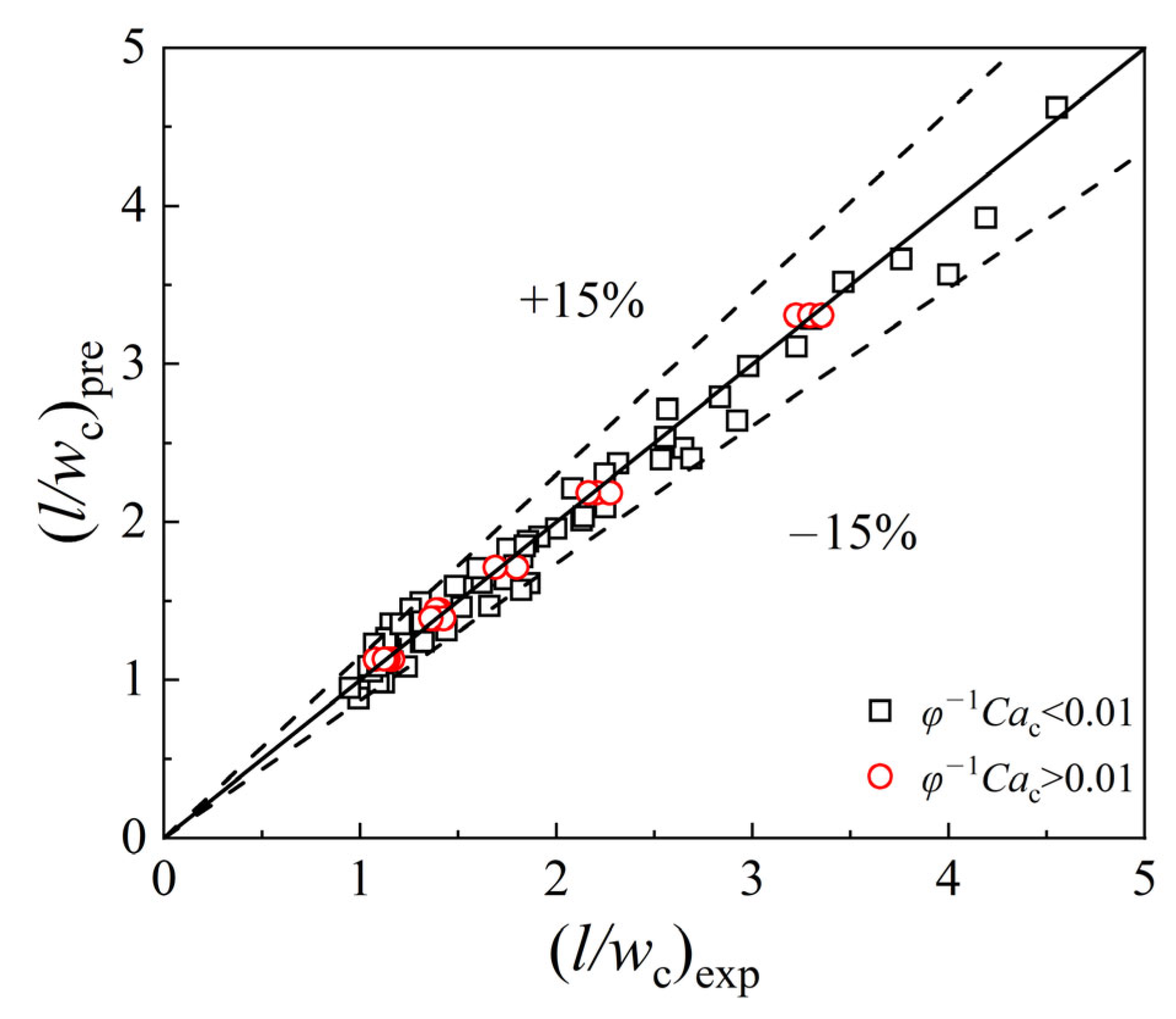
Figure 7 shows the comparison between the predicted value (l/wc)pre and the experimental value (l/wc)exp of the dimensionless droplet size of the slug flow in two regions. The average relative errors of Equations (5) and (6) are 4.92% and 2.89%, respectively. Moreover, the maximum relative errors of these equations are 12.17% and 5.12%, respectively. The relative error is expressed as below:
The average relative error is expressed as below:
It can be seen from the predictions of Formulas (5) and (6) that the dimensionless orifice size shows significant effects on the droplet size of the slug flow. Additionally, the value of the exponent of the dimensionless orifice size wor/wc is larger when φ−1Cac > 0.01, which means that the focusing effect of the orifice is much stronger in this region.
4. Conclusions
In the present study, experimental research on the liquid–liquid two-phase flow and the size prediction of slug droplets in flow-focusing microchannels with different orifice sizes were carried out. The following conclusions were drawn:
- (1)
- Three flow patterns were observed regardless of the configuration of the microchannel: slug flow, dripping flow, and jetting flow. Then, the flow pattern maps were presented based on the Reynolds number of the dispersed phase Red and the Capillary numbers of the continuous phase Cac. Importantly, it was found that the downstream orifice size of the microchannel had a momentous influence on the flow pattern of the liquid–liquid two-phase: with a decrease in the orifice size, there were shifts of the slug–dripping transition and dripping–jetting transition to lower Cac values. Meanwhile, the slug flow region decreased in area but the jetting flow region increased in area with the decrease in orifice size. Furthermore, a composite term of , and Reor(d), was adopted to form the universal flow map including the slug and dripping flow while the universal flow map including the dripping and the jetting flow was constructed based on and Reor(d).
- (2)
- The effects of the operating conditions on the droplet size of slug flow were investigated. It was ascertained that the dimensionless slug droplet size l/wc decreases with the increment of the flow rate of the continuous phase Qc and the flow rate ratio of the two-phase φ. Additionally, l/wc increases with the augmentation of the flow rate of the dispersed phase Qd and the orifice size wor. Meanwhile, l/wc decreases firstly and then remains nearly constant with the increase in the dimensionless number φ−1Cac, and the critical dimensionless number of the transition is about (φ−1Cac)cirt ≈ 0.01. The mechanisms of droplet formation in both regions were investigated: when φ−1Cac < 0.01, the droplet formation was mainly driven by the squeezing force Fp, while when φ−1Cac > 0.01, both the squeezing force Fp and the shear force Fτ contributed to the droplet formation, and the downstream orifice provided a stronger focusing effect in this region. Furthermore, the dimensionless slug droplet size could be predicted by the correlation equation with the flow rate ratio of the two-phase φ, the Capillary number of the continuous phase Cac, and the dimensionless orifice size wor/wc. When φ−1Cac < 0.01, the correlation could be expressed as ; when φ−1Cac > 0.01, the prediction formula was . The predicted results were in good agreement with the experimental values.
Significantly, this research provides experimental and theoretical support for liquid–liquid two-phase flows and the size prediction of slug droplets in microchannels. Meanwhile, it also presents a reference for the optimal designing of a microchannel device.
Author Contributions
Software, D.L.; Data curation, L.W.; Writing—original draft, W.D.; Writing—review & editing, Y.D. All authors have read and agreed to the published version of the manuscript.
Funding
This research was funded by the National Natural Science Foundation of China (No. 22008195), the three-year action plan project of Xi’an University (No. 2021XDJH37), the Special Scientific Research Plan of the Education Department of Shaanxi Province (No. 19JK0743 and No. 18JK0516), the project of “The Youth Innovation Team of Shaanxi Universities” (Environmental Pollution Monitoring and Control Innovation Team, 51), and Xi’an University’s interdisciplinary construction project (No. XY2023JC02).
Data Availability Statement
The data are not publicly available due to some authors’ personal privacy.
Conflicts of Interest
The authors declare no conflict of interest.
Nomenclature
| A | The cross-sectional area of the orifice, μm2 |
| B | The cross-sectional area of the gap between the forming droplet and the channel wall, μm2 |
| dh | Equivalent size of orifice section, μm |
| Fp | Squeezing force, (kg·m)/s2 |
| Fτ | Shear force, (kg·m)/s2 |
| h | Depth of the channel, μm |
| l | Length of the slug droplet, μm |
| lo | Length of the drop head, μm |
| lor | Length of the orifice of the microchannel, μm |
| L | Orifice perimeter, μm |
| n | Numbers of the slug droplet |
| ΔPc | Pressure drop of the continuous phase, Pa |
| Qd | Volumetric flow rate of dispersed phase, mL·h−1 |
| Qc | Volumetric flow rate of continuous phase, mL·h−1 |
| u | Superficial velocity of liquid, m·s−1 |
| wc | Width of the channel, μm |
| w0 | Width of the droplet head when the neck of the dispersed phase is initially formed, μm |
| wor | Width of the orifice of the channel, μm |
| Greek letters | |
| α | Parameter |
| β | Parameter |
| ε | the thickness of the fluid film, μm |
| μ | Viscosity of liquid, mPa·s |
| ρ | Density of liquid, kg·m−3 |
| σ | Surface tension of liquid, mN·m−1 |
| φ | The flow ratio of continuous phase to disperse phase (φ = Qc/Qd) |
| θ | Contact angle, ° |
| Dimensionless groups | |
| Ca | Capillary number (Ca = uμ/σ) |
| Oh | Ohnesorge number (Oh = μ/(ρσwc)1/2) |
| Re | Reynolds number (Re = ρwcu/μ) |
| We | Weber number (We = CaRe = ρwcu2/σ) |
| Subscripts | |
| c | Continuous phase |
| crit | Critical dimensionless number |
| d | Dispersed phase |
| exp | The experimental value (l/wc)pre of the dimensionless droplet size of slug flow |
| gap | Gap between the forming droplet and the channel wall |
| or | The orifice of the microchannel |
| pre | The predicted value (l/wc)pre of the dimensionless droplet size of the slug flow |
References
- Nehme, R.; Blel, W.; Montillet, A.; Bellettre, J.; Marchal, L. Production of oil in water emulsions in microchannels at high throughput: Evaluation of emulsions in view of cosmetic, nutraceutical or pharmaceutical applications. Chem. Eng. Process. Process Intensif. 2021, 161, 108301. [Google Scholar] [CrossRef]
- Stone, H.A.; Kim, S. Microfluidics basic issues, applications, and challenges. AIChE J. 2001, 47, 1250–1254. [Google Scholar] [CrossRef]
- Al-Azzawi, M.; Mjalli, F.S.; Husain, A.; Al-Dahhan, M. A Review on the Hydrodynamics of the Liquid-Liquid Two-Phase Flow in the Microchannels. Ind. Eng. Chem. Res. 2021, 60, 5049–5075. [Google Scholar] [CrossRef]
- Qian, J.Y.; Li, X.J.; Wu, Z.; Jin, Z.J.; Sunden, B. A comprehensive review on liquid-liquid two-phase flow in microchannel: Flow pattern and mass transfer. Microfluid. Nanofluidics 2019, 23, 116. [Google Scholar] [CrossRef]
- Cao, Z.; Wu, Z.; Sundén, B. Dimensionless analysis on liquid-liquid flow patterns and scaling law on slug hydrodynamics in cross-junction microchannels. Chem. Eng. J. 2018, 344, 604–615. [Google Scholar] [CrossRef]
- Cubaud, T.; Mason, T.G. Capillary threads and viscous droplets in square microchannels. Phys. Fluids 2008, 20, 053302. [Google Scholar] [CrossRef]
- Wang, C.L.; Tian, M.C.; Zhang, J.Z.; Zhang, G.M. Experimental study on liquid–liquid two-phase flow patterns and plug hydrodynamics in a small channel. Exp. Therm. Fluid Sci. 2021, 129, 110455. [Google Scholar] [CrossRef]
- Ma, H.Y.; Zhao, Q.K.; Yao, C.Q.; Zhao, Y.C.; Chen, G.W. Effect of fluid viscosities on the liquid-liquid slug flow and pressure drop in a rectangular microreactor. Chem. Eng. Sci. 2021, 241, 116697. [Google Scholar] [CrossRef]
- Fu, T.T.; Wu, Y.N.; Ma, Y.G.; Li, H.Z. Droplet formation and breakup dynamics in microfluidic flow-focusing devices: From dripping to jetting. Chem. Eng. Sci. 2012, 84, 207–217. [Google Scholar] [CrossRef]
- Kovalev, A.V.; Yagodnitsyna, A.A.; Bilsky, A.V. Viscosity Ratio Influence on Liquid-Liquid Flow in a T-shaped Microchannel. Chem. Eng. Technol. 2020, 44, 365–370. [Google Scholar] [CrossRef]
- Zhang, Q.; Liu, H.C.; Zhao, S.N.; Yao, C.Q.; Chen, G.W. Hydrodynamics and mass transfer characteristics of liquid–liquid slug flow in microchannels: The effects of temperature, fluid properties and channel size. Chem. Eng. J. 2019, 358, 794–805. [Google Scholar] [CrossRef]
- Yagodnitsyna, A.A.; Kovalev, A.V.; Bilsky, A.V. Flow patterns of immiscible liquid-liquid flow in a rectangular microchannel with T-junction. Chem. Eng. J. 2016, 303, 547–554. [Google Scholar] [CrossRef]
- Shin, H.C.; Senguttuvan, S.; Kim, S.M. Experimental study on sub-regimes of air-water slug flow in a rectangular micro-channel. Int. J. Mech. Sci. 2023, 259, 108577. [Google Scholar] [CrossRef]
- Bordbar, A.; Kheirandish, S.; Taassob, A.; Kamali, R.; Ebrahimi, A. High-viscosity liquid mixing in a slug-flow micromixer: A numerical study. J. Flow Chem. 2020, 10, 449–459. [Google Scholar] [CrossRef]
- Etminan, A.; Muzychka, Y.S.; Pope, K. A review on the hydrodynamics of Taylor flow in microchannels: Experimental and computational studies. Processes 2021, 9, 870. [Google Scholar] [CrossRef]
- Talimi, V.; Muzychka, Y.S.; Kocabiyik, S. A review on numerical studies of slug flow hydrodynamics and heat transfer in microtubes and microchannels. Int. J. Multiph. Flow 2012, 39, 88–104. [Google Scholar] [CrossRef]
- Etminan, A.; Muzychka, Y.S.; Pope, K. Liquid film thickness of two-phase slug flows in capillary microchannels: A review paper. Can. J. Chem. Eng. 2021, 100, 325–348. [Google Scholar] [CrossRef]
- Roumpea, E.; Kovalchuk, N.M.; Chinaud, M.; Nowak, E.; Simmons, M.J.H.; Angeli, P. Experimental studies on droplet formation in a flow-focusing microchannel in the presence of surfactants. Chem. Eng. Sci. 2019, 195, 507–518. [Google Scholar] [CrossRef]
- Lei, L.; Zhao, Y.T.; Chen, W.K.; Li, H.L.; Wang, X.Y.; Zhang, J.Z. Experimental studies of droplet formation process and length for liquid–liquid two-phase flows in a microchannel. Energies 2021, 14, 1341. [Google Scholar] [CrossRef]
- Zhao, N.; Long, W.; He, Y.Q. Dynamic behavior and driving force model of droplet formation in a T-junction microchannel. J. Micromech. Microeng. 2019, 29, 115002. [Google Scholar]
- Thorsen, T.; Roberts, R.W.; Arnold, F.H.; Quake, S.R. Dynamic pattern formation in a vesicle-generating microfluidic device. Phys. Rev. Lett. 2001, 86, 4163–4166. [Google Scholar] [CrossRef] [PubMed] [Green Version]
- Garstecki, P.; Fuerstman, M.J.; Stone, H.A.; Whitesides, G.M. Formation of droplets and bubbles in a microfluidic T-junction-scaling and mechanism of break-up. Lab Chip 2006, 6, 437–446. [Google Scholar] [CrossRef] [PubMed]
- Xu, J.H.; Li, S.W.; Tan, J.; Luo, G.S. Correlations of droplet formation in T-junction microfluidic devices: From squeezing to dripping. Microfluid. Nanofluid. 2008, 5, 711–717. [Google Scholar] [CrossRef]
- Tsaoulidis, D.; Angeli, P. Effect of channel size on liquid-liquid plug flow in small channels. AIChE J. 2016, 62, 315–324. [Google Scholar] [CrossRef] [Green Version]
- Wu, L.Y.; Liu, X.D.; Zhao, Y.J.; Chen, Y.P. Role of local geometry on droplet formation in axisymmetric microfluidics. Chem. Eng. Sci. 2017, 163, 56–67. [Google Scholar] [CrossRef]
- Korczyk, P.M.; van Steijn, V.; Blonski, S.; Zaremba, D.; Beattie, D.A.; Garstecki, P. Accounting for corner flow unifies the understanding of droplet formation in microfluidic channels. Nat. Commun. 2019, 10, 2528. [Google Scholar] [CrossRef] [Green Version]
- Du, W.; Fu, T.T.; Zhang, Q.D.; Zhu, C.Y.; Ma, Y.G.; Li, H.Z. Breakup dynamics for droplet formation in a flow-focusing device: Rupture position of viscoelastic thread from matrix. Chem. Eng. Sci. 2016, 153, 255–269. [Google Scholar] [CrossRef]
- Zhang, Q.D.; Fu, T.T.; Zhu, C.Y.; Ma, Y.G. Formation and size prediction of slug droplet in viscoelastic fluid in flow-focusing microchannel. CIESC J. 2016, 67, 504–511. [Google Scholar]
- Carrier, O.; Ergin, F.G.; Li, H.Z.; Watz, B.B.; Funfschilling, D. Time-resolved mixing and flow-field measurements during droplet formation in a flow-focusing junction. J. Micromech. Microeng. 2015, 25, 084014. [Google Scholar] [CrossRef]
- Fatehifar, M.; Revell, A.; Jabbari, M. Non-Newtonian Droplet Generation in a Cross-Junction Microfluidic Channel. Polymers 2021, 13, 1915. [Google Scholar] [CrossRef]
- Song, Q.; Yang, Z.; Chen, Y.; Luo, X.L.; Chen, J.Y.; Liang, Y.Z. Effect of local geometry on droplet formation in flow-focusing microchannel. CIESC J. 2020, 71, 1540–1553. [Google Scholar]
- Christopher, G.F.; Noharuddin, N.N.; Taylor, J.A.; Anna, S.L. Experimental observations of the squeezing-to-dripping transition in T-shaped microfluidic junctions. Phys. Rev. E 2008, 78, 036317. [Google Scholar] [CrossRef]
- Du, W.; Fu, T.T.; Duan, Y.F.; Zhu, C.Y.; Ma, Y.G.; Li, H.Z. Breakup dynamics for droplet formation in shear-thinning fluids in a flow-focusing device. Chem. Eng. Sci. 2018, 176, 66–76. [Google Scholar] [CrossRef]
Figure 1.
(a) Schematic diagram of the system for liquid–liquid two-phase flow. (b) Schematic diagram of microchannel. Unit: mm. (c) Left column: geometries of the channels near the cross junction (dashed line box in (b)). Right column: the two immiscible fluids meet at the cross junction of the microchannels.
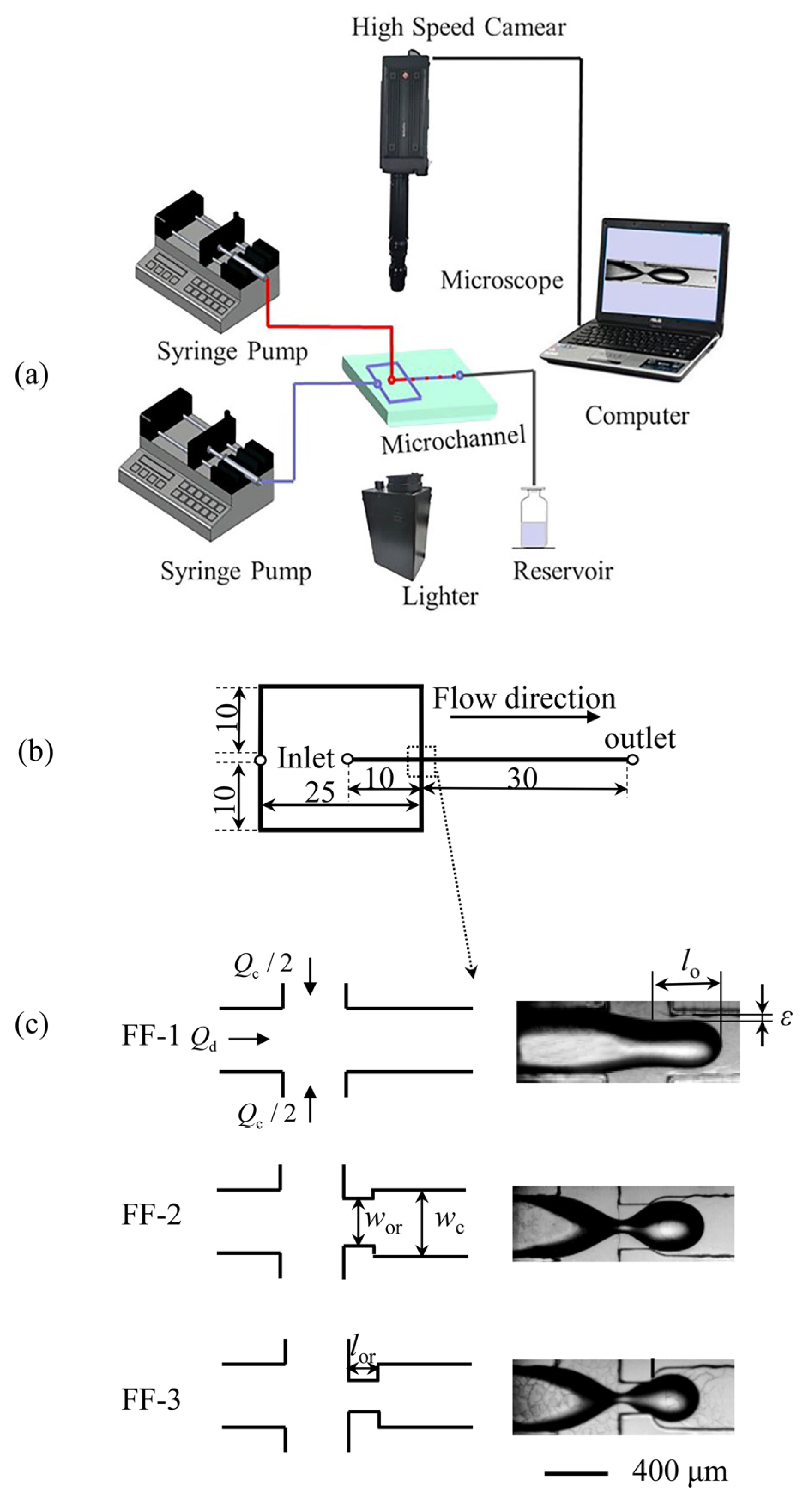
Figure 2.
Liquid–liquid two-phase flow patterns in microchannels with different orifice sizes; Qd = 0.4 mL/h.
Figure 2.
Liquid–liquid two-phase flow patterns in microchannels with different orifice sizes; Qd = 0.4 mL/h.
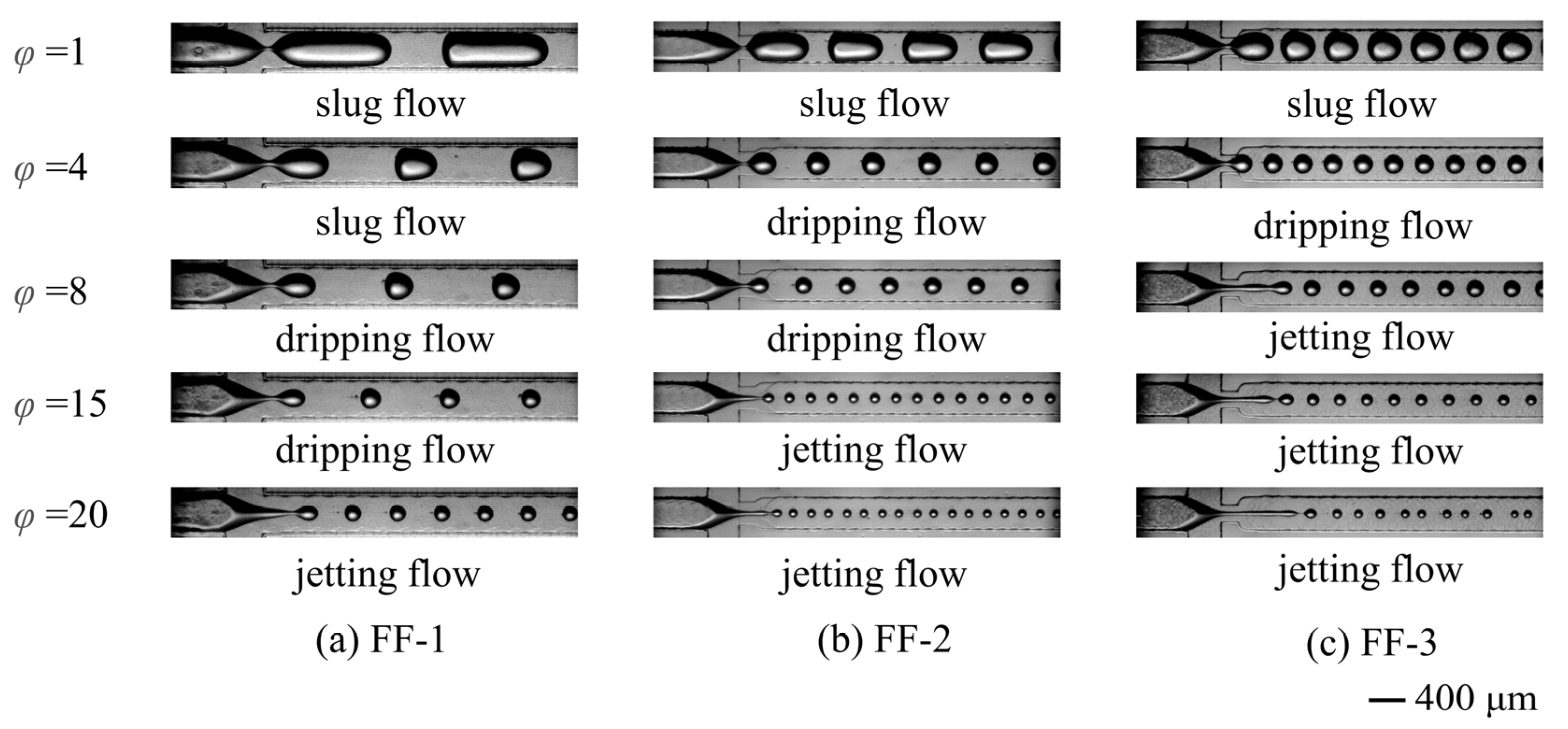
Figure 3.
Flow pattern maps and transition lines of the adjacent flow pattern. (a) FF-1; (b) FF-2; (c) FF-3; (d) summary of transition lines of the adjacent flow pattern in three microchannels. Solid lines—transition lines from slug to dripping flow; dash lines—transition lines from dripping to jetting flow.

Figure 4.
Proposed flow pattern maps and transition lines in microchannels with different orifice sizes. (a) Transition from slug flow to dripping flow; (b) transition from dripping flow to jetting flow.
Figure 4.
Proposed flow pattern maps and transition lines in microchannels with different orifice sizes. (a) Transition from slug flow to dripping flow; (b) transition from dripping flow to jetting flow.

Figure 5.
Effects of the operating conditions on the dimensionless droplet size l/wc. (a) Effects of the flow rate of the continuous phase Qc and the dispersed phase Qd on l/wc in FF-1. (b) Effects of the orifice size on l/wc; Qd = 0.2 mL/h. (c) Effects of the dimensionless number φ−1Cac and φ on l/wc in FF-1.
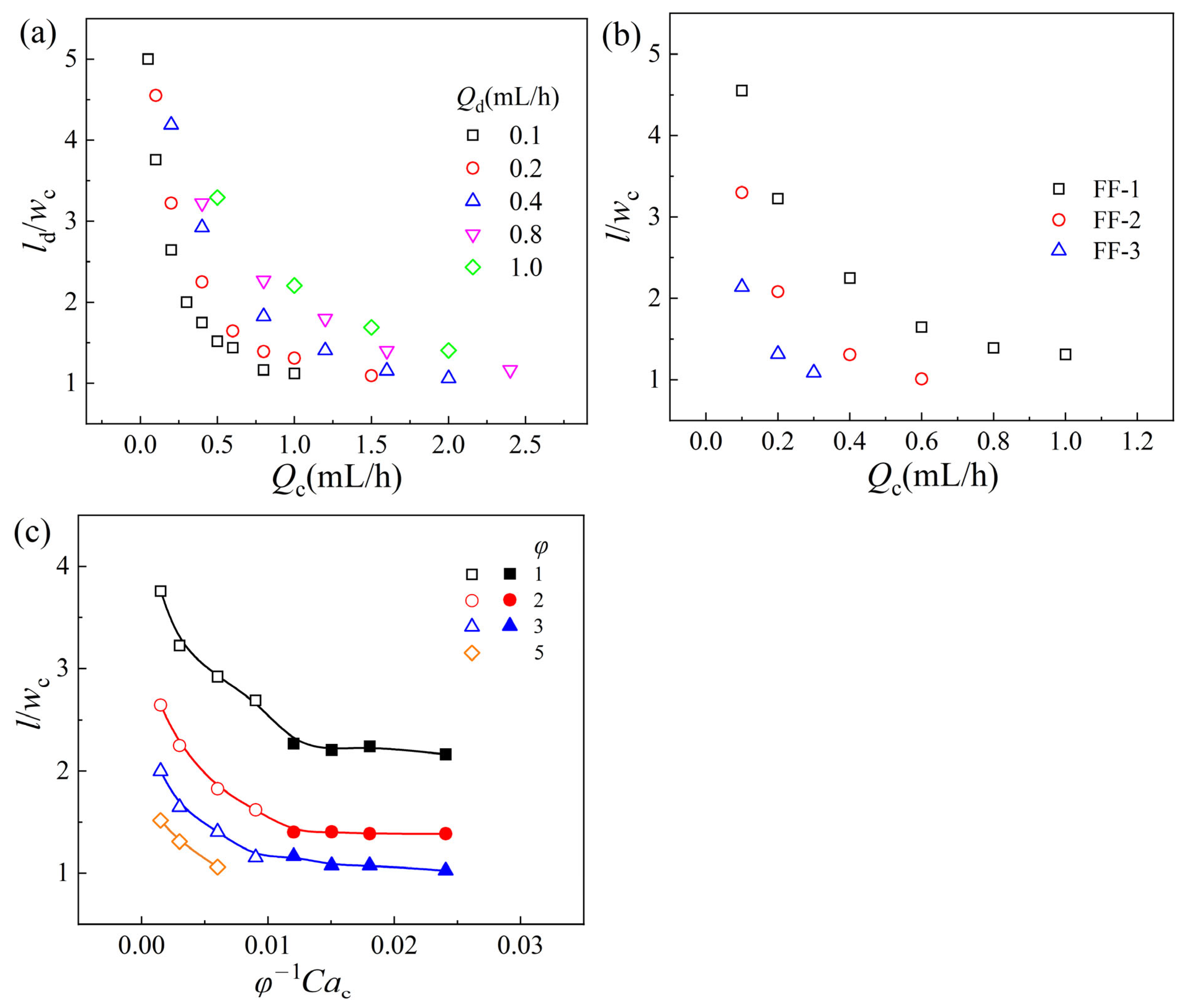
Figure 6.
Effects of the operating conditions on the (a) squeezing force Fp and (b) shear force Fτ. FF-1.
Figure 6.
Effects of the operating conditions on the (a) squeezing force Fp and (b) shear force Fτ. FF-1.
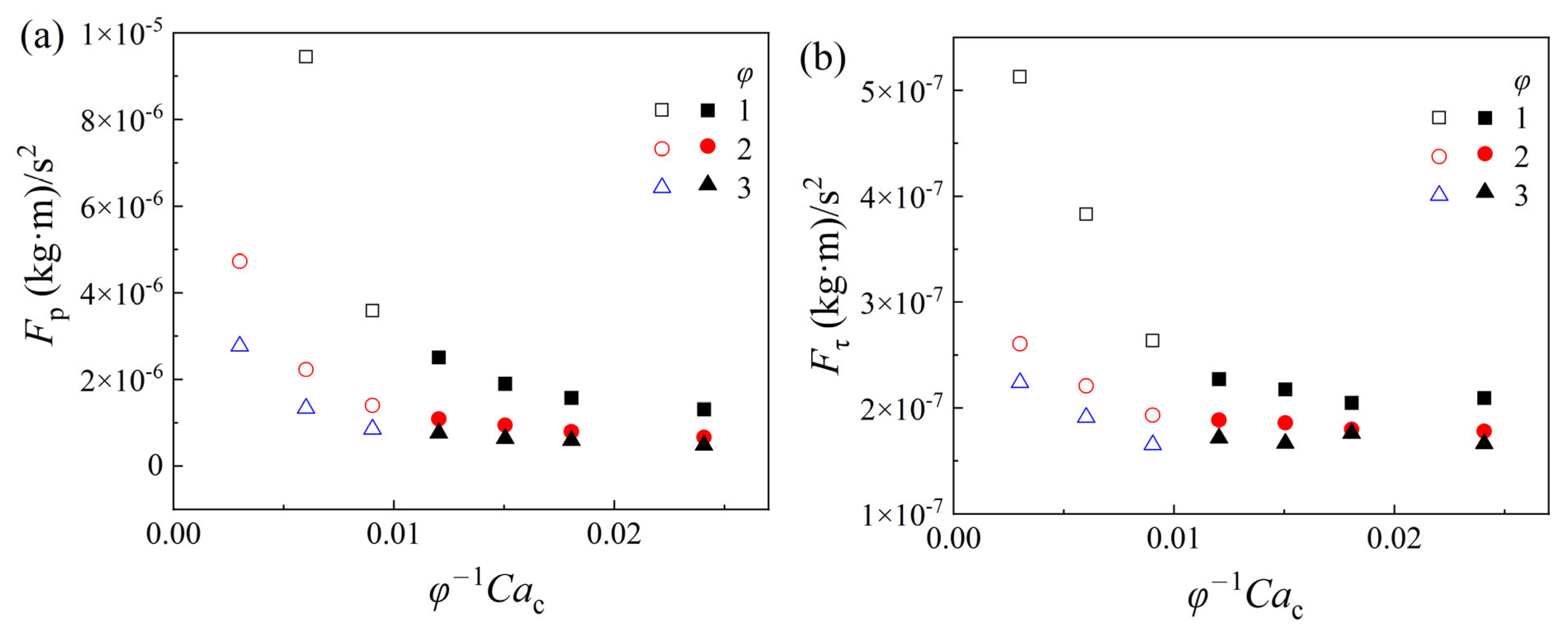
Figure 7.
Comparison between calculated values (l/wc)pre of and experimental data (l/wc)exp on slug droplet size.
Figure 7.
Comparison between calculated values (l/wc)pre of and experimental data (l/wc)exp on slug droplet size.
Disclaimer/Publisher’s Note: The statements, opinions and data contained in all publications are solely those of the individual author(s) and contributor(s) and not of MDPI and/or the editor(s). MDPI and/or the editor(s) disclaim responsibility for any injury to people or property resulting from any ideas, methods, instructions or products referred to in the content. |
© 2023 by the authors. Licensee MDPI, Basel, Switzerland. This article is an open access article distributed under the terms and conditions of the Creative Commons Attribution (CC BY) license (https://creativecommons.org/licenses/by/4.0/).
Share and Cite
MDPI and ACS Style
Du, W.; Duan, Y.; Wang, L.; Liu, D. Liquid–Liquid Two-Phase Flow and Size Prediction of Slug Droplets in Microchannels. Processes 2023, 11, 2390. https://doi.org/10.3390/pr11082390
AMA Style
Du W, Duan Y, Wang L, Liu D. Liquid–Liquid Two-Phase Flow and Size Prediction of Slug Droplets in Microchannels. Processes. 2023; 11(8):2390. https://doi.org/10.3390/pr11082390
Chicago/Turabian StyleDu, Wei, Yingfeng Duan, Lina Wang, and Dayu Liu. 2023. "Liquid–Liquid Two-Phase Flow and Size Prediction of Slug Droplets in Microchannels" Processes 11, no. 8: 2390. https://doi.org/10.3390/pr11082390
Note that from the first issue of 2016, this journal uses article numbers instead of page numbers. See further details here.