
Investigation on the Dynamics of a Flexible Multi-Body System of a Three-Cylinder Gasoline Engine Crankshaft
College of Engineering, China Agricultural University, Beijing 100083, China
*
Author to whom correspondence should be addressed.
Processes 2023, 11(4), 1248; https://doi.org/10.3390/pr11041248
Submission received: 6 March 2023
/
Revised: 7 April 2023
/
Accepted: 10 April 2023
/
Published: 18 April 2023
(This article belongs to the Special Issue Advanced Technologies and Materials for Sustainability in Energy Systems and Environmental Processes)
Abstract
:Three-cylinder gasoline engines are increasingly favored by major automobile manufacturers due to their good fuel economy, low manufacturing cost and low fuel consumption. However, the inherent balance problem has an adverse effect on the vibration of the whole engine and even the comfort of the whole vehicle, which limits its application in high-end models. This paper studied the dynamics characteristic of the flexible multi-body system of the three-cylinder gasoline engine crankshaft. A dynamic simulation model of the flexible multi-body system of the three-cylinder gasoline engine crankshaft is established through the flexible treatment of the engine crankshaft. The kinematics and dynamics characteristics of each component of the crankshaft connecting rod system are obtained by analyzing the kinematics and dynamics characteristics of the engine shafting system. The relevant factors affecting the vibration of the engine crankshaft system are studied through the establishment of the analysis model of the torsional vibration of the engine crankshaft. This is of great significance to further improve and optimize the design of the three-cylinder gasoline engine.
1. Introduction
In order to achieve the mid-century goal of energy saving and emissions reduction, countries around the world have established stringent fuel consumption and emissions regulations, and these have promoted the development of automotive powertrains toward energy efficiency and effectiveness [1,2,3]. Fuel-fired or hybrid vehicles powered mainly by internal combustion engines still occupy a major share of the international automotive market due to battery life issues of electric vehicles (EVs). According to the total European car sales data, pure electric vehicles in Europe in 2022 only accounted for 11% of all car sales [4]. Small displacement three-cylinder engines have unique advantages over traditional four-cylinder engines in terms of power density, fuel consumption, size and weight of the external structure, as well as advantages in terms of ease of design, manufacturing and assembly due to the reduction of moving parts, and thus a reduction in friction losses during the work process [5,6,7,8]. However, the influence of its inherent structural layout on the dynamic balance characteristics of the crankshaft system will lead to vibration problems for the whole machine, which in turn reduces the NVH performance of the whole vehicle, and this has become one of the main factors limiting the large-scale application of three-cylinder machines [9,10]. As the power core of a three-cylinder gasoline engine, the dynamic characteristics of the power crankshaft system directly affect the smoothness of the gasoline engine operation. Therefore, scholars from various countries have paid great attention to it and carried out continuous optimization. Li et al. [11] carried out a kinematic analysis by analyzing the crank-link mechanism of a certain engine, and based on this analysis, the inertia force of the piston assembly and the gas force were analyzed, and the existing crank-link mechanism was optimized. Liu et al. [12] analyzed the crankshaft modalities in free and constrained states based on the crankshaft structure and operating loads of a six-cylinder engine using a finite element analysis, and optimized the engine crankshaft structure to reduce the crankshaft mass and rotational inertia while ensuring the safety factor and structural strength. Bai et al. [13] analyzed and discussed the inherent frequency and vibration pattern of the engine crankshaft and optimized the structure of the crankshaft considering the stress concentration effect, and this provided a theoretical basis for further solving the existing engine crankshaft vibration problems, it also provided a reference for the direction of the structural improvement of the engine crankshaft. Li et al. [14] conducted a modal analysis of the crankshaft of a four-cylinder engine and the results were applied to guide the design parameters of the crank wall to reduce the effect of dangerous vibration patterns on the crankshaft. Zhao et al. [15] studied the three-dimensional coupled vibration characteristics of the crankshaft by analyzing the nonlinear factors affecting the crankshaft rotation, and the results showed that the flywheel rotational inertia and the main bearing radius clearance had a greater influence on the vibration of the crankshaft in all directions, and the oil supply pressure had a smaller influence on the vibration. M. Inagaki et al. [16] applied finite element and multi-body dynamics methods to construct an internal combustion engine vibration analysis system, and realized the study of crankshaft coupling dynamics through analytical calculations, connecting rod, crankshaft and engine block. It can be found that the dynamic characteristics of the crankshaft connecting rod system play a decisive role in the smooth operation of the internal combustion engine. In this paper, the kinematics and dynamics characteristics of the crankshaft system are obtained through the establishment of a flexible multi-body dynamics model of the three-cylinder gasoline engine crankshaft connecting rod system. Compared with other engine crankshaft system models, the rigid-flexible coupling multi-body kinematics and dynamics simulation of the crankshaft system can be carried out by the proposed model, and the dynamic loads of the crankshaft system can be analyzed from the simulation results, and this provides a theoretical basis for further research on the engine vibration and dynamics characteristics of the three-cylinder engine [17]. It also has an important guiding role for the optimal design of the three-cylinder engine and the engines with a large crankshaft [18].
2. Simulation Modeling of a Crankshaft Flexible Multi-Body System of a Three-Cylinder Gasoline Engine
Figure 1 shows the flow chart of the dynamics simulation model of the flexible multi-body system of the crankshaft of a three-cylinder gasoline engine. In order to establish the crankshaft as an elastic deformation body in the simulation model, the crankshaft modal analysis model is established using Ansys 2022R1 finite element analysis software, and the calculation results are exported as MNF files and imported into Adams 2019 software together with the piston connecting rod and other 3D models, and the crankshaft flexible multi-body dynamics simulation model is established by optimizing the boundary condition settings of the flexible body.
2.1. Engine Crankshaft Finite Element Modeling
As one of the main components of engine power transmission, the crankshaft is subject to alternating stresses during operation. Therefore, it is of great importance to optimize the crankshaft structure through a finite element simulation to ensure the strength and life of the crankshaft, and thus ensure the smooth operation of the crankshaft.
For the finite element analysis of the crankshaft, the crankshaft contact surface is idealized as a rectangle with a width of 2b according to the Hertzian stress theory calculation, and the crankshaft stress calculation equation is derived as [19]:
The meaning of each symbol is shown in Table 1. Taking the crankshaft studied in this article as an example, the specific positions represented by and in Formula (1) are shown in Figure 2.
During normal engine operation, the piston pushes the connecting rod to turn the crankshaft as an external input excitation acting on the crankshaft itself, causing it to twist and vibrate to some extent. Once resonance is generated, the crankshaft deformation spikes and may cause the engine to fail to operate properly. Therefore, the crankshaft vibration modal analysis is also important to measure the crankshaft operating condition.
Considering that the load applied to the crankshaft is generally distributed in most cases, the equation of motion can be expressed as:
where M is the mass matrix of the finite unit on the crankshaft after the flexibilization process; C is the damping matrix of the finite unit on the flexible body of the crankshaft; K is the stiffness matrix of the finite unit on the flexible body of the crankshaft. , and are the acceleration, velocity and displacement vectors generated during the crankshaft rotation, respectively. is the load vector of the physical nodes.
Under the condition of free vibration without damping, the equation of motion of the crankshaft can be expressed as:
Using the modal matrix converting Equation (3) to modal coordinates Q:
Following the simplification, there is:
where is the generalized mass matrix, is the generalized stiffness matrix and is the modal load vector.
In order to save computational resources and improve the efficiency of the computer operation, the generalized mass matrix and generalized stiffness matrix are discretized, then it can be expressed as:
where is the modulus of elasticity. is the stress matrix and is the strain matrix. and are the form function matrices. is the density of the crankshaft unit mass. When is involved in the calculation as a function of time, the calculation is inevitably too large, then load as a linear combination of a series of static loads that varies with time can be reduced to:
In summary, the eigenvalue equation for the case of free vibration of the crankshaft without damping can be obtained as:
where is the main vibration pattern of the crankshaft vibration in the nth order mode and the intrinsic frequency of the nth order mode is determined.
2.2. Analysis of the Crankshaft Meshing Results
The 3D model of the engine crankshaft was drawn using Inventor 2022 software, and the drawn crankshaft 3D file was imported into Ansys Workbench 2021R1 for the modal simulation model building. In the model, the crankshaft material is defined as steel with an elastic modulus of 2.06 GPa, Poisson’s ratio of 0.3 and a density of 7850 kg/m3. The relevance center option was removed from Ansys version 2021R1 and merged into the default option. Considering the actual size of the crankshaft model and the related physical characteristics, the mesh independence analysis was performed first when the finite element model was built to determine the most economical meshing settings in terms of computational resources and computational time with guaranteed computational accuracy. The relationship between the number of grid cells and the mean deformation of the crankshaft obtained from the vibration modal analysis is used as the criterion of independence, and the data in Table 2 are obtained.
It can be observed in Figure 3 that when the number of meshes is greater than 1,000,000, the effect of refining the mesh on the average deformation of the mode will be reduced, and it is obvious that the accuracy of the calculation results will be guaranteed, and the computational resources will be maximally saved when the cell size is less than 2 mm. Following each independence test, the physical preference (physics preference) is finally set to mechanical when meshing (mechanical), the cell size is set to 2 mm, and the size adjustment (sizing) is set to seven levels of resolution with the slow transition of the edges. Inflation sets the smoothing ratio to 0.272, the expansion layer to five layers, the growth rate to 1.2, and the smooth transition and the number of iterative layers to five. The expansion layer algorithm system divides the mesh from the edge, then refines the edge mesh at the curvature, then produces the surface mesh, and finally produces the body mesh. The final finite element model of the crankshaft is statistically generated with 1,006,786 nodes and 673,009 cells. Using the cell mass as the mesh metric, the minimum mesh mass of the crankshaft model is 0.15133, the maximum is infinitely close to 1, and the average mass is 0.815887. The mesh division results are shown in Figure 4.
The dynamics characteristics of the crankshaft are the result of the combined effect of the crankshaft mass, material properties, structural shape and constraints. Since no constraints and forces are applied to the crankshaft, and the first six orders obtained from the modal analysis correspond exactly to the three translational and rotational degrees of freedom of the rigid body motion, the elastic deformation can be considered infinitely small, so the deformation energy is infinitely small and the frequency is close to zero. Therefore, after analyzing the vibration modes of orders 1~30, orders 7~30 are retained for subsequent operations. Table 3 shows the crankshaft intrinsic frequencies of orders 7~30. By analyzing the vibration diagram, the vibration forms and bending vibration directions under different order modes can be obtained. Once the analysis of the dynamics characteristics of the crankshaft is completed, the relevant results are integrated and exported to the MNF file to provide a technical basis for the subsequent dynamics modeling.
Figure 5 shows the seventh -order mode of the crankshaft, the crankshaft vibration in this mode is mainly in the form of torsional vibration around the X-axis, because the crankshaft is in the unconstrained and force conditions, so the deformation at both ends is the largest, i.e., the amplitude is the largest, and the first and third curvatures near the main journal are the location of the smallest amplitude. Figure 6 shows the eighth-order mode of the crankshaft, and the vibration nodes appear at the first and third crankshafts. The vibration of the crankshaft in this mode is mainly in the form of torsional vibration around the Y-axis, and the amplitude of the free end of the crankshaft is the largest, followed by the flywheel end. Figure 7 shows the ninth-order mode vibration diagram of the crankshaft. The vibration nodes of the crankshaft in this mode are at the first, second and third main journals, and the vibration is mainly in the form of local vibration at the crankshaft abutment, and the amplitude of the free end is also the largest.
According to the analysis, the crankshaft vibration mode from the seventh to the thirtieth order has different vibration manifestations and main occurrence parts, and the representative tenth to fifteenth order mode vibration patterns are listed as shown in Figure 8. Obviously, in the tenth to fifteenth order, the maximum amplitude occurs at different curvatures. The sixteenth to thirtieth order amplitude diagrams are similar and will not be repeated.
2.3. Adams-Based Crankshaft Flexible Multi-Body Dynamics Modeling
Using ANSYS APDL, calculate the crankshaft vibration modal description file with the suffix “.MNF” by establishing stiffness points and setting stiffness regions. Based on the actual working conditions of the crankshaft, this article defines five rigid regions at the two ends of the studied crankshaft, where needle bearings are installed, and at the center of the three crankshafts, as shown in Figure 9. The rigid area does not deform in the flexible body by default, which is more closely related to the actual operating state of the engine crankshaft. The crankshaft connecting rod three-dimensional assembly model based on inventor can be established after generating the Parasolid file with the suffix .x_t and importing it to Adams in cooperation with the MNF file to simulate the kinematic dynamics of the crankshaft connecting rod system. Considering the actual physical parameters and working conditions, the materials (Table 4) are set for the main components of the crankshaft connecting rod system kinematic dynamics simulation model, and the constraints (Table 5) are added. The final simulation model is shown in Figure 10.
The kinematic dynamics simulation model of the crankshaft connecting rod system is simplified and only includes the actual engine piston with rings, both sides are equipped with snap springs, etc. In the simulation model, the X direction is the direction of gravity, the Y direction is the axial direction of the crankshaft and the Z direction is the radial direction of the crankshaft.
3. Simulation Analysis of the Kinematic Dynamics of the Crankshaft Connecting Rod System of the Three-Cylinder Engine
In Adams/View, add a drive for the rotating sub between the crankshaft and the bearings. Set the engine to run at a constant speed of 3800 r/min or 22,800 deg/s. Set the simulation step length to 500 and the simulation time to 0.096 s, during which the shaft system can complete three work cycles. During the simulation, Adams/View automatically calculates the kinematic and mechanical properties of the model. The overall coordinates are used as the reference coordinates during the simulation analysis. The piston, piston pin, crank pin and other components are analyzed separately on this basis.
3.1. Kinematic Analysis
For the piston, it moves from the upper stop to the lower stop with a stroke of S = 2R. The case of the movement of the piston is analyzed using the simplified side view of the crankshaft system, as shown in Figure 11.
If the initial position of the piston is at the upper stop , at this time and , then its displacement can be expressed as:
From the geometric relationship, we have , and . Where is the ratio of the connecting rod. Equation (9) can be expressed as:
As and are kept stable, the piston displacement is only related to the crank rotation angle. Upon obtaining the velocity expression, the velocity of the piston can be expressed as [20]:
Therefore, the velocity of the piston can be expressed as the sum of the two synthetic motions and . Similarly, after obtaining the velocity relationship, the acceleration of the piston can be obtained by again deriving these expressions:
The above analysis treats the crankshaft as a rigid body, while the actual crankshaft is a flexible body that will deform under external excitation. Due to the occurrence of torsional deformation and vibration deformation, the displacement, velocity and acceleration curves of the piston will be deformed to a certain extent, but the period and variation patterns reflected in the expressions can still be clearly reflected in the actual crankshaft kinematics simulation.
The piston pins and connecting rods connected to the pistons also appear as rigid bodies in the crankshaft system, and their kinematics are similar to those of the pistons and will not be described here.
3.2. Piston Kinematics Simulation
Figure 12, Figure 13 and Figure 14 are the displacement, velocity and acceleration variation patterns of the first, second and third pistons, respectively. Depending on the reference plane position and considering the deformation of the crankshaft caused by vibration, the maximum positive displacement of the first and third pistons is approximated to be 26.97 mm, and the maximum negative displacement is −33.47 mm. The maximum positive displacement of the second piston is 36.64 mm, and the maximum negative displacement is −28.45 mm. The maximum velocity of the first piston is 20,036.23 mm/s and the minimum velocity is 1.56 mm/s. Similarly, the maximum and minimum velocities of the second piston are 19,215.54 mm/s and 2.13 mm/s, respectively. The acceleration is also affected by the vibration, there is a sharp change in the localization, and the maximum and minimum acceleration of the first and third pistons are similar, which are 4.99 × 108 mm/s2 and 10,253 × 108 mm/s2, respectively. It can be seen that the deformation generated by the crankshaft torsional vibration has a certain influence on the piston motion, which is manifested by the abnormal values of velocity and acceleration, thus leading to the decrease of the smoothness of the piston motion.
3.3. Linkage Kinematics Simulation
The results of the kinematic analysis of the engine connecting rod are shown in Figure 15, Figure 16 and Figure 17. In this engine model, only the crankshaft is treated flexibly, which means the deformation only occurs in the crankshaft during the motion. The rest of the components are treated as rigid bodies, so the connecting rod is connected to the piston through the piston pin, and its displacement, velocity and acceleration change patterns are the same and, these can also be affected by the deformation generated by the torsional vibration of the crankshaft, except for the different kinematic starting points.
3.4. Force Analysis of the Crankshaft System
The crankshaft system is simplified using Inventor 2022 software. The center of mass of the piston system, which consists of the piston, the piston pin and piston ring parts, is determined to be at the center of the piston pin axis with an overall mass of . The piston system, which is mainly composed of piston pins and piston rings, is located at the center of the piston pin axis, and the overall mass is and , respectively.
For a composite system consisting of a piston system and a two-shore system, the main reciprocating and rotational inertial forces are applied during normal operation. The inertial forces on each moving part can be obtained by multiplying each converted mass by the acceleration of the corresponding motion:
where is the reciprocating motion mass in the composite system and ; is the crank radius. is the angular velocity of the crank rotation.
In the crank linkage mechanism, the rotating members are the crank and the connecting rod that moves in a plane. In the analysis, the rotational motion of the crank is considered as the uniform rotation. Therefore, after the mass conversion, the rotational inertia force of the crank connecting rod set is
where is the rotational moving mass in the composite system. Similarly, the gas force most used on the piston can be expressed as:
where D is the piston diameter and is the actual gas pressure acting on the piston.
During the reciprocating motion of the piston, the reciprocating inertia force and the gas force are much larger than the rest of the force, so the main force can be expressed as:
The distribution of forces is shown in Figure 18, the combined force is decomposed to obtain the radial and axial forces on the connecting rod.
3.5. Force Analysis of the Crank Pin
As the main connection between the crankshaft and the piston, the crank pin plays an irreplaceable role in power transmission, so it is extremely important to analyze the tangential and radial forces of the first, second and third crank pins. It can be found in Figure 19, Figure 20 and Figure 21 that the tangential and radial force curves of the first and third crank pins are basically the same, and their forces show a different trend to that of the second crank pins. The crankshaft of the three-cylinder gasoline engine is connected to the engine housing by needle bearings at the left and right ends, and when the crankshaft is running at a high speed, the bearings have a certain limiting effect on the crankshaft vibration deformation, and the vibration modal analysis shows that compared with the second crank pin, the first and third crank pin deformation is smaller, and the stress generated is correspondingly smaller. Furthermore, in Figure 19 and Figure 21, the peak force of the first and third crank pins is maintained at 3.2 × 10⁶ N, which is much smaller than the peak force of the second crank pin of 5.2 × 10⁷ N. The second crank pin, which is located in the middle of the crankshaft, carries most of the stress during the engine operation. For the second crank pin with the largest force, the theoretical analysis shows that the maximum stress state at the crankshaft is accompanied by the piston running acceleration of 0. However, because the crankshaft will twist and vibrate to a certain extent after the force is applied, the maximum stress state will occur within a certain period of time. By analyzing the stress state and crankshaft torsional vibration during the simulation process, it is easy to find that for the second crank pin, which is under the greatest stress, the maximum stress state occurs in the first to fourth states, as shown in Figure 22. The first to fourth states correspond to different crankshaft rotation angles and the second piston runs upward at this time. In the first and second states, the color of the stress-strain cloud at the second crank pin deepens, and this represents the gradual increase of the stress, corresponding to the stress state in the time period from 0.0505 to 0.0522, as shown in Figure 20. Similarly, the stresses in the third and fourth states reach their maximum, and these correspond to the stresses in the time period from 0.0522 to 0.0532, as shown in Figure 19, after which the cloud color gradually lightens and the stresses gradually decrease.
The vibration pattern of the same position of the crankshaft can be influenced by the running speed. A vibration amplitude can be found on the crankshaft when the running speed is set to 3800 r/min. The three crank pin radial tangential stresses basically remain synchronized, i.e., they appear on the 0-axis side at the same time, but when running to the piston limit position, the amplitude increases leading to the crank pin radial tangential stresses distributed on both sides of the 0-axis in a certain time, but the overall change trend is basically the same.
3.6. Piston Pin Force Analysis
From Figure 23, Figure 24 and Figure 25, it can be found that the form of the change of the load on the piston pin and the value of the load on the piston pin are basically the same. The piston pin is relatively stable in the small time period at the beginning of the motion because the torsional vibration deformation at the crankshaft crank is not obvious. With the crankshaft movement, when the maximum point of amplitude moves to the crankshaft, the stability of the piston movement decreases and the force on the piston pin changes substantially. It can be found in the piston acceleration change graph that the acceleration concentration changes in the time domain, and the acceleration of large fluctuations causes the piston pin force to change sharply. At the same time, the force of the piston pin varies closely to the vibration model, and the deformation at the crankshaft is more frequent and larger than that of the main journal, which can cause stress concentration and damage the crankshaft system. It can also be concluded by analyzing the force situation in Figure 23, Figure 24 and Figure 25, that both sides of the piston pin force are basically the same and their force situation is significantly less than that of the central piston pin, which is basically consistent with the crank pin force relationship under the influence of its position.
3.7. Torsional Vibration Analysis of the Crankshaft
The vibration deformation of the crankshaft can be obtained by studying the displacement and angle change in the simulation analysis. Therefore, the location where the largest amplitude of torsional vibration of the crankshaft is selected and the location can be influenced by the running speed. In this paper, measurement points were set up at the free end of the crankshaft and at the three crankshafts to determine the torsional vibration deformation of the engine. In this study, the engine’s running speed is set to the rated speed (3800 r/min). The data of vibration amplitude are extracted for each test point under this condition, followed by a Fourier transformation (FFT) to convert the time domain plot to the frequency domain plot. Finally, the torsional amplitude values of the test points are obtained.
3.7.1. Test Point Arrangement
The arrangement of the test points has a direct impact on the results of the torsional vibration analysis, and the test points are shown in Figure 26. These are Marker1_1~Marker1_3, Marker2_1~Marker2_2, Marker3_1~Marker3_2, Marker4_1~Marker4_2 and Marker5. Considering that the maximum torsional vibration occurs at the free end of the crankshaft and at the three crankshaft turns, the reference point Marker1_1 is set on the right-hand surface of the free end of the crankshaft, and the two reference points are fixed on the ground and in a different position along the gravity direction are set as Marker1_2 and 1_3. When the torsional vibration deformation does not occur, the three points are located on the same line and the crankshaft does not turn. As the crankshaft remains stable, the three points are located in the one axis. The angle measurement unit Mea_Angle1_1 is created with Marker1_1 as the middle marker and Marker1_2 and 3 as the starting and final markers, respectively. Obviously, when the crankshaft is stationary, the angle is at 0°. Once the torsional vibration occurs, Angle1 changes synchronously with the change of the Marker1 position, and the degree of change depends on the distance between Marker1_2 and Marker1_3.
Based on the same arrangement, four points fixed on the ground are set on the crankshaft central axis, three of them are the intersection points between the cross-sections over the first, second and third crankshaft centers and the crankshaft central axis, which are Marker2_1, Marker3_1 and Marker4_1, respectively. The fourth point is defined as Marker5, and only needs to fall on the central axis. The intersection points of the above cross-sections with the corresponding curved inflection mid-axes are defined as Marker2_2, Marker3_2 and Marker4_2, respectively. Finally, the corresponding measurement points are assembled to create the angle measurement cell Mea_Angle2_1 with Marker2_1 as the intermediate marker point and Marker2_2 and Marker5 as the starting and final marker points, respectively, and these are similar to Mea_Angle3_1 and Mea_Angle4_1.
3.7.2. Analysis of the Crankshaft Torsional Vibration
The torsional vibration situation of the free end of the crankshaft is analyzed at a running speed of 3800 r/min. As shown in Figure 27, the engine crankshaft torsional vibration deformation is caused by the cylinder burst pressure, and the reciprocating moment of inertia of the parts in the spectrum, the fourteenth harmonic amplitude, is already very small, so the vibration amplitude after the fifteenth harmonic can be approximated as 0.
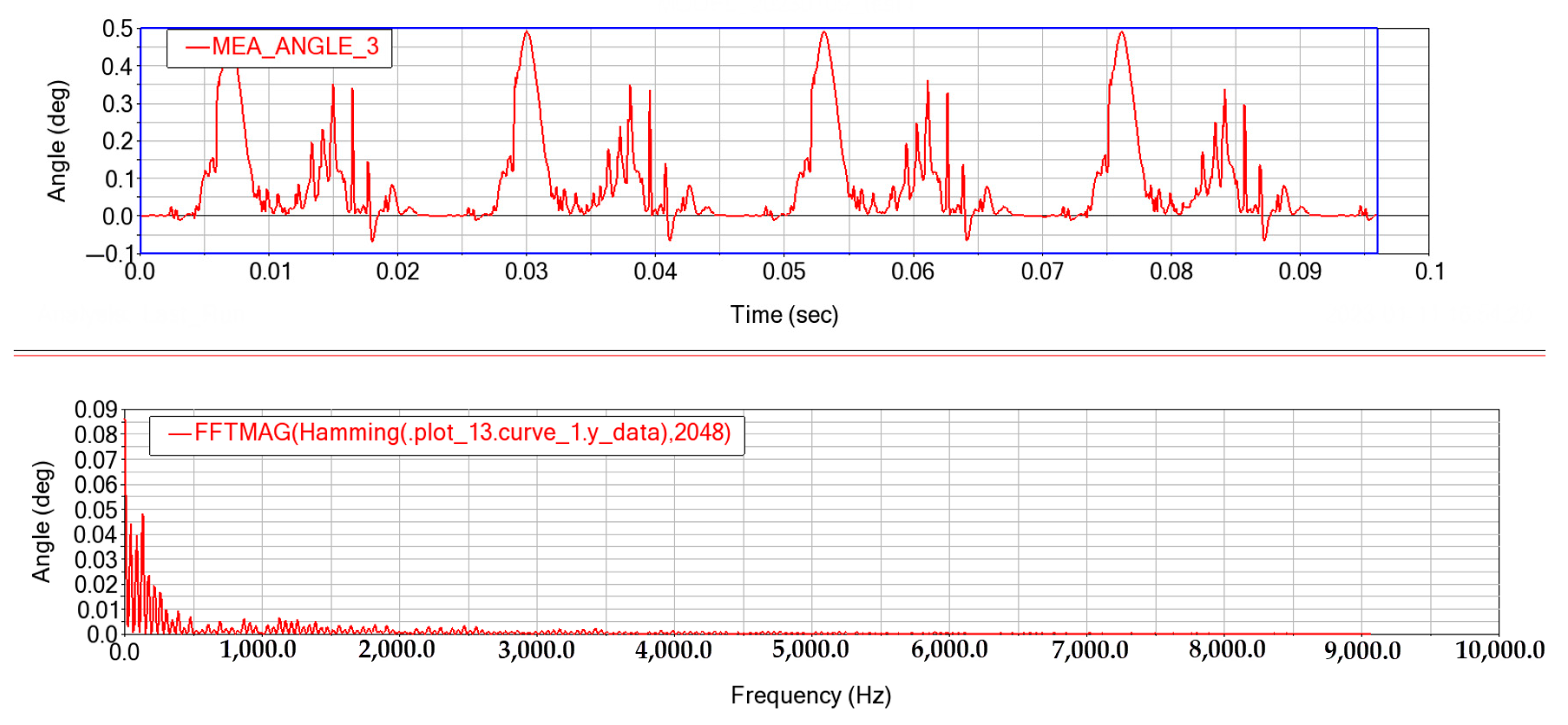
Similarly, the torsional vibrations of the first, second and third cranks are analyzed, and the results are shown in Figure 28, Figure 29 and Figure 30. It can be found that the harmonic components of each order of the cylinder burst pressure and the reciprocating inertial force are the main factors that cause the torsional vibration of the crankshaft system through the analysis of the time domain and frequency domain characteristics of the simulation results, that can be influenced by the order modes, and the effect is greatest at a low order, and decreases sharply when the order increases. This is because the mode shape of the crankshaft is a compound vibration formed by the superposition of multiple simple harmonic vibrations. The higher the vibration mode order, the faster the attenuation caused by the damping effect, so the larger vibration deformation will only occur in the low-order mode, and then the vibration deformation will attenuate as the mode order increases. When the engine is operating at rated speed, the crankshaft will produce significant first-order torsional resonance, which should be taken seriously.
To obtain the torsional vibration of the crankshaft under different working conditions, different rotational speeds are applied to the crankshaft, and the results are shown in Figure 31 and Figure 32.
It is not difficult to find that after giving the engine different speeds, the number of operations varies for the same running time. When the running speed of the crankshaft is set to 1400 r/min, the engine can run for two complete cycles, and the frequency (Hz) curve in Figure 31 shows a relatively obvious continuity of the harmonic amplitude change due to the frequency change in the spectrum during the process. When the running speed of crankshaft is set to 3800 r/min, the harmonic amplitude has obvious discrete points. This also shows that it is difficult to achieve a significant reduction in harmonic amplitude through a small change in speed after resonance occurs at this speed, and the only feasible way is to avoid operating the engine at this speed.
Four complete engine working cycles can be obtained as the running speed of the crankshaft is set to 2600 r/min, and the frequency (Hz) curve in Figure 31 shows that at this state, the change in frequency brings about a change in harmonic amplitude similar to the discrete point characteristic at 3800 r/min. the harmonic amplitude can be effectively reduced by a small change in speed.
4. Conclusions
The dynamics simulation of the crankshaft flexible multi-body system is the basis to complete the optimization design of the engine crankshaft connecting rod system. In this paper, ANSYS workbench, ANSYS APDL and ADMAS View were used to simulate the dynamics of the flexible system of a crankshaft connecting rod system of a three-cylinder gasoline engine. The following conclusions can be drawn:
- The modal and torsional vibration analyses of the crankshaft can help guide the study of engine dynamics to a certain extent. The first 20~30 orders of the modal analysis for the crankshaft are proposed for the simulation calculation. The crankshaft vibration patterns of different orders mainly show the superimposed combination of the bending vibration and torsional vibration around the X/Y/Z axis;
- The dynamic model of the crankshaft flexible multi-body system of the three-cylinder engine is established by analyzing the kinematics and dynamics of the engine crankshaft connecting rod mechanism and considering the attribute values and operating characteristics of each component. The simulation analysis of the multi-body system dynamics of the shafting system is completed under the rated speed condition, and the kinematics and dynamics characteristics of the crankshaft system are obtained;
- The largest bending and torsional vibration deformation can be found at the second crank. This can affect the movement of the moving parts connected to it, resulting in varying forces on these various components, which can lead to premature fatigue failure of these components. In addition, the vibration deformation around the first and third cranks is smaller than that of the second crank, which can lead to stress concentration to the second crank and related parts, which can be confirmed by analyzing the force, displacement, velocity, and acceleration between the parts connected to the first, second and third cranks;
- The kinematic analysis can accurately obtain the kinematic response, such as the stress distribution and maximum stress for one working cycle. The natural frequency of the crankshaft system can be obtained through the constrained modal analysis of the engine crankshaft system, and engine resonance can be avoided by optimizing the operating speed and crankshaft size, thereby improving the engine life.
Author Contributions
L.Z. performed the conceptualization, writing—review & editing and project administration. X.Z. performed the data curation, validation and writing—original draft preparation. All authors have read and agreed to the published version of the manuscript.
Funding
This research received no external funding.
Institutional Review Board Statement
Not applicable.
Informed Consent Statement
Not applicable.
Data Availability Statement
The data that support the findings of this study are available from the corresponding author upon reasonable request.
Conflicts of Interest
The authors declare no conflict of interest.
References
- Hoen, K.M.R.; Tan, T.; Fransoo, J.C.; van Houtum, G.J. Effect of carbon emission regulations on transport mode selection under stochastic demand. Flex. Serv. Manuf. J. 2014, 26, 170–195. [Google Scholar] [CrossRef]
- Toptal, A.; Özlü, H.; Konur, D. Joint decisions on inventory replenishment and emission reduction investment under different emission. Int. J. Prod. Res. 2014, 52, 243–269. [Google Scholar] [CrossRef]
- Hirose, K.; Matsumura, T. A comparison between emission intensity and emission cap regulations. Energy Policy 2020, 137, 111115. [Google Scholar] [CrossRef]
- Kastanaki, E.; Giannis, A. Dynamic estimation of end-of-life electric vehicle batteries in the EU-27 considering reuse, remanufacturing and recycling options. J. Clean. Prod. 2023, 393, 136349. [Google Scholar] [CrossRef]
- Friedfeldt, R.; Zenner, T.; Ernst, R.; Fraser, A. Three-cylinder gasoline engine with direct injection. MTZ Worldw. 2012, 73, 4–11. [Google Scholar] [CrossRef]
- Flierl, R.; Hannibal, W.; Schurr, A.; Neugä, J. Turbocharged three-cylinder engine with activation of a cylinder. MTZ Worldw. 2014, 75, 22–27. [Google Scholar] [CrossRef]
- Guo, R.; Zhou, Z. Influence of mass unbalancing of three-cylinder engine on idle vibration based on powertrain model. Vibroeng. Procedia 2019, 9, 81–86. [Google Scholar] [CrossRef]
- Liu, X.A.; Shangguan, W.B.; Lv, Z.P.; Ahmed, W.; Zhu, W. A study on optimization method of a powertrain mounting system with a three-cylinder engine. Proc. Inst. Mech. Eng. Part C J. Mech. Eng. Sci. 2017, 231, 2235–2252. [Google Scholar] [CrossRef]
- Hooper, P.R. Low noise, vibration and harshness solutions for in-line three-cylinder range extender and hybrid electric vehicles. Int. J. Engine Res. 2021, 2, 581–591. [Google Scholar] [CrossRef]
- Eichler, F.; Demmelbauer-Ebner, W.; Persigehl, K.; Wendt, W. The 1.0-l Three-Cylinder TSI Engine in Volkswagen’s Modular. MTZ Worldw. 2014, 75, 18–23. [Google Scholar]
- Li, L.-B.; Wang, C.; Yin, J.-D.; Shen, Y.; Wang, R.-P. Kinematic analysis of crank-link mechanism. Intern. Combust. Engine 2017, 4, 49–52. [Google Scholar]
- Liu, J.; Lu, Q.x. Research on optimization of engine crankshaft structure based on finite element analysis. Agric. Mech. Res. 2022, 44, 241–252. [Google Scholar]
- Bai, B.Q.; Wang, Y. Modal analysis and structural optimization of V-type engine crankshaft based on Abaqus. Model. Simul. 2022, 11, 636–647. [Google Scholar] [CrossRef]
- Li, X.M.; Cui, C.Q.; Xu, H.L. Modal analysis of crankshaft of a four-cylinder engine. Hebei Agric. Mach. 2015, 9, 60–61. [Google Scholar]
- Zhao, J.S.; Li, B.C.; Li, H.; Baibin, L.; Zhang, C.D. Study of crankshaft three-dimensional coupled vibration characteristics with the influence of nonlinear parameters. Vib. Shock. 2020, 39, 198–205. [Google Scholar]
- Inagaki, M.; Kawamoto, T.; Yamamoto, K. Prediction of structural and kinematic coupled vibration on internal combustion engine. RD Rev. Toyota CRDL 2002, 37, 2. [Google Scholar]
- Mourelatos, Z.P. An efficient crankshaft dynamic analysis using substructuring with Ritz vectors. J. Sound Vib. 2000, 238, 495–527. [Google Scholar] [CrossRef]
- Nozdrzykowski, K.; Grządziel, Z.; Nozdrzykowska, M.; Grzejda, R.; Stępień, M. Eliminating the Influence of Support Conditions on Geometric Shape Measurements of Large Crankshafts of Marine Engines. Energies 2023, 16, 16. [Google Scholar] [CrossRef]
- Sestieri, A. SDM applications to machine tools and engines. Sadhana 2000, 25, 305–317. [Google Scholar] [CrossRef]
- Zhang, Q.; Zuo, Z.; Liu, J. Failure analysis of a diesel engine cylinder head based on finite element method. Eng. Fail. Anal. 2013, 34, 51–58. [Google Scholar] [CrossRef]
Figure 1.
Flow chart for the flexible multi-body dynamics modeling of the crankshaft.

Figure 2.
Location of Equation (1) and .
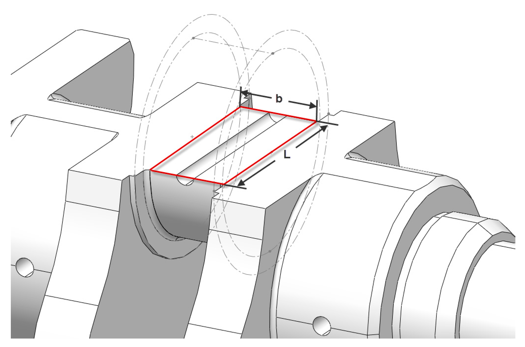
Figure 3.
Grid independence test.

Figure 4.
Crankshaft meshing results.
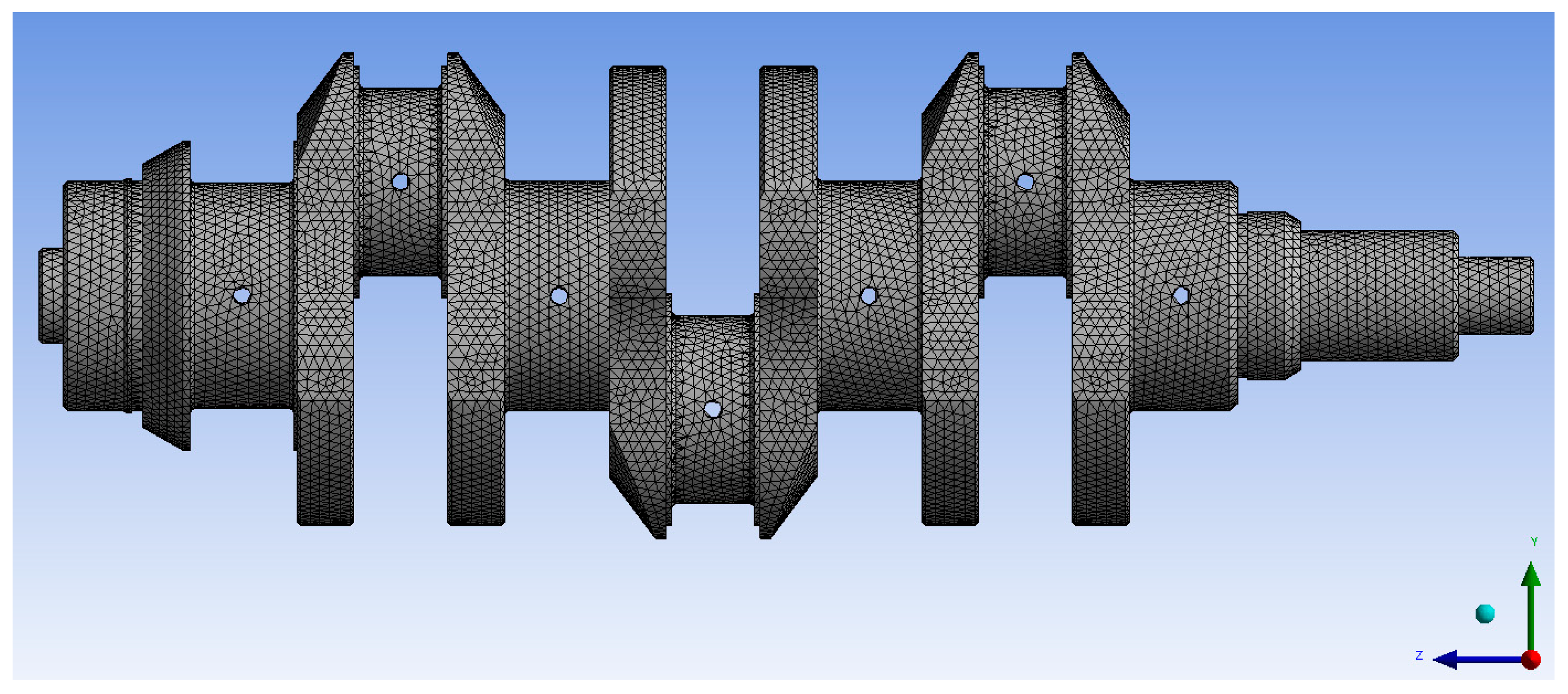
Figure 5.
Seventh order mode vibration diagram.
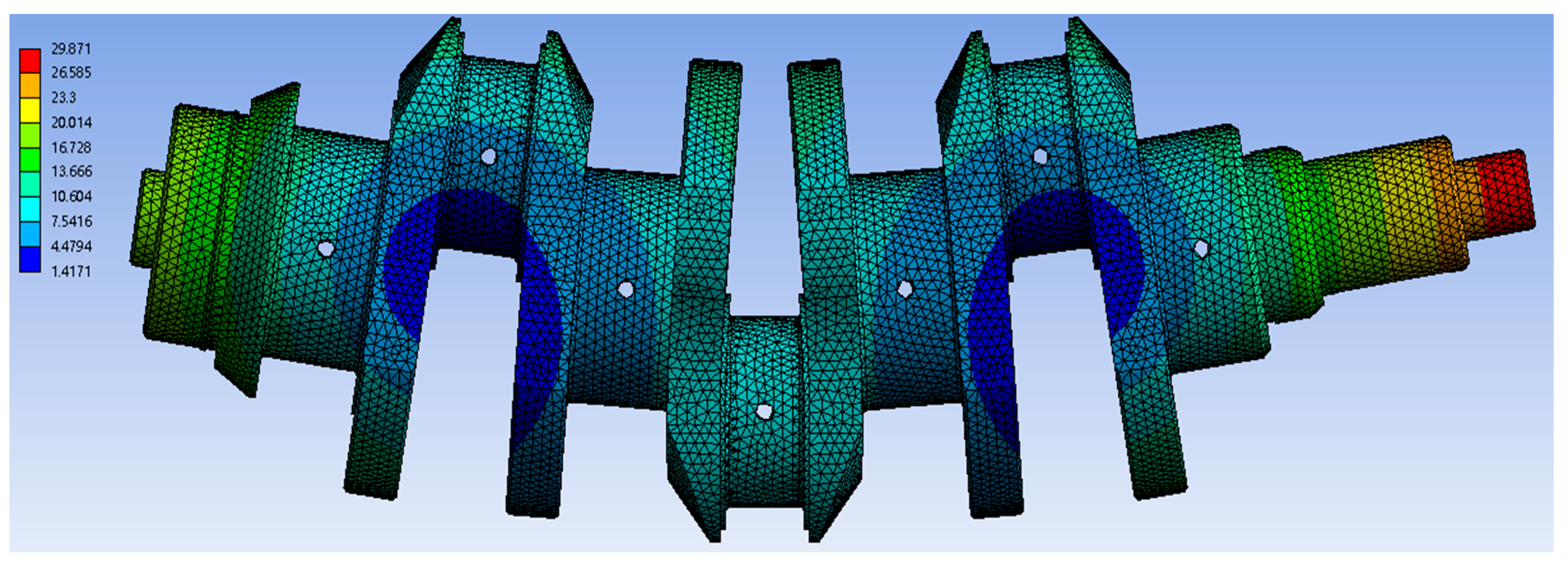
Figure 6.
Eighth order mode vibration diagram.

Figure 7.
Ninth order modal vibration diagram.

Figure 8.
Tenth to thirtieth order modal vibration diagram.

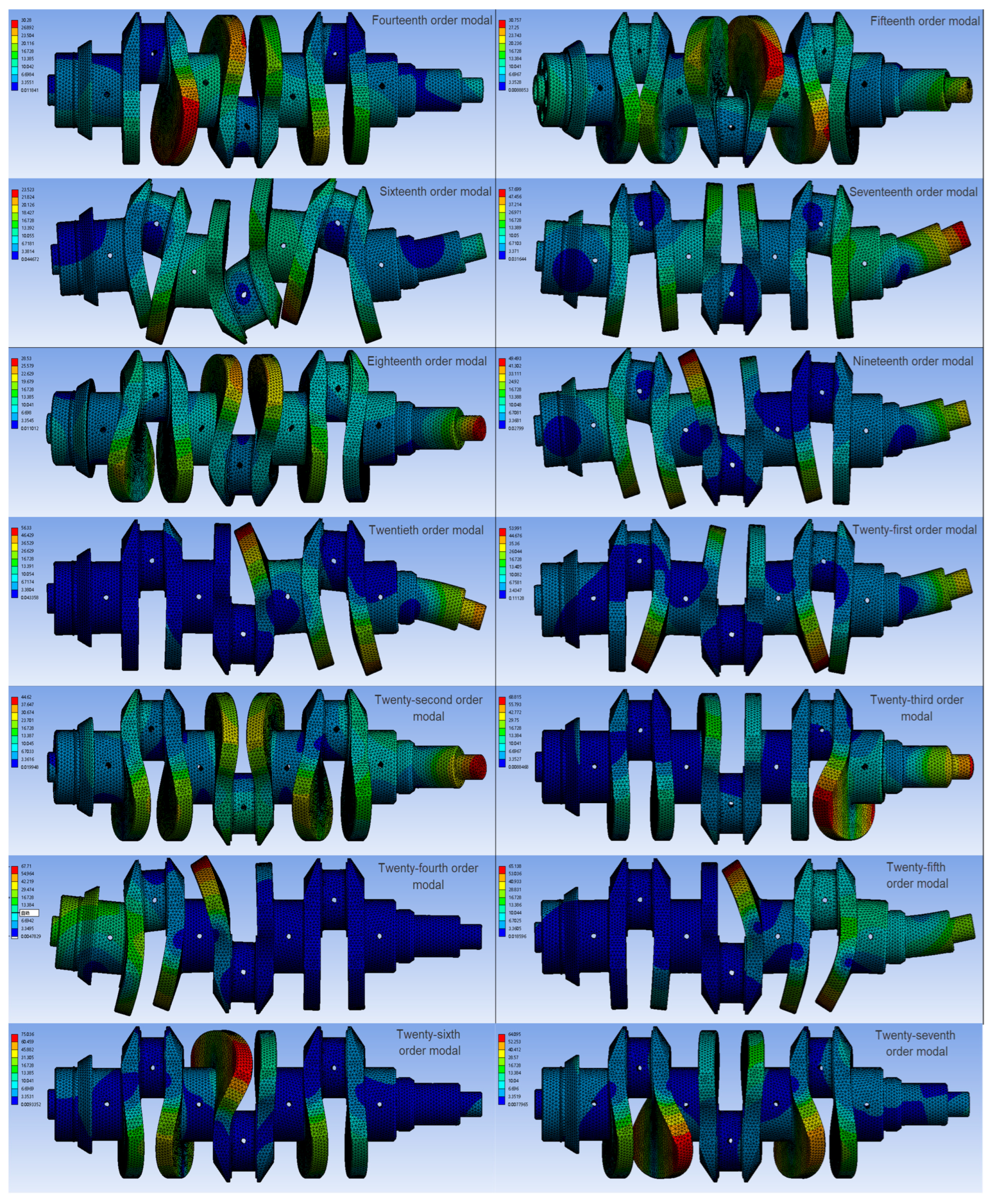

Figure 9.
Rigid point setting of the flexible body.
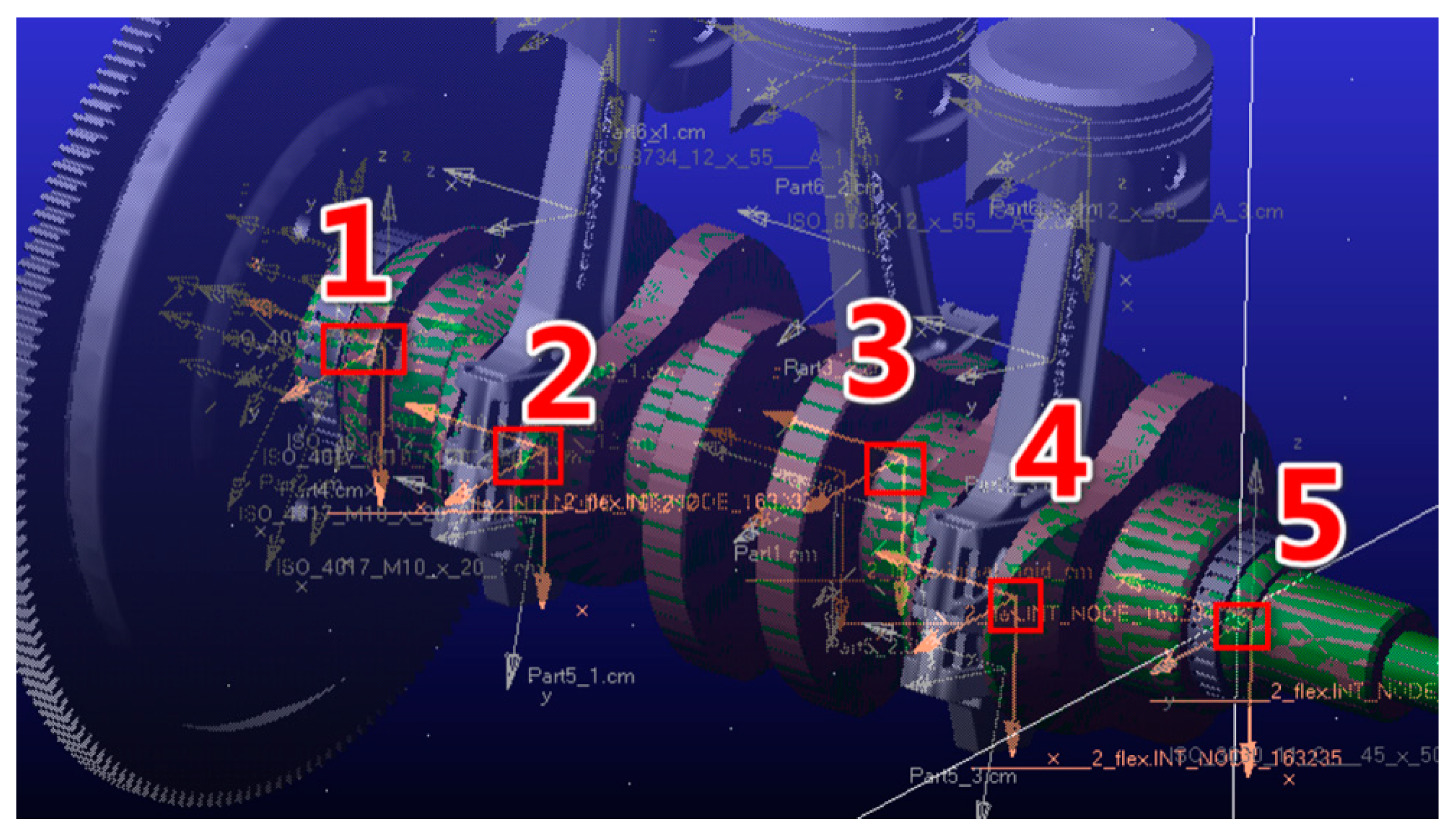
Figure 10.
Adams simulation model.

Figure 11.
Simplified side view of crankshaft system.
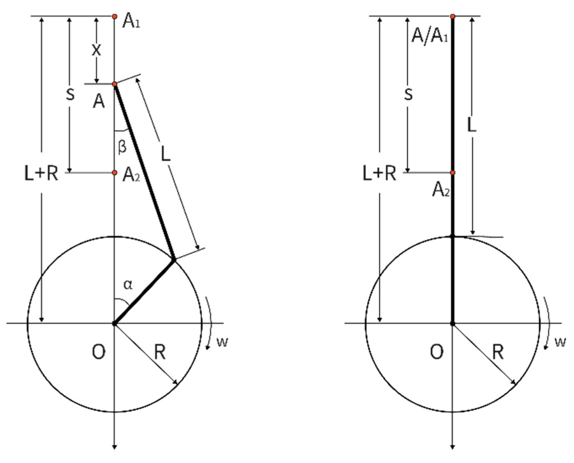
Figure 12.
Engine piston displacement curve.

Figure 13.
Engine piston speed curve.

Figure 14.
Engine piston acceleration diagram.

Figure 15.
Engine connecting rod displacement curve.
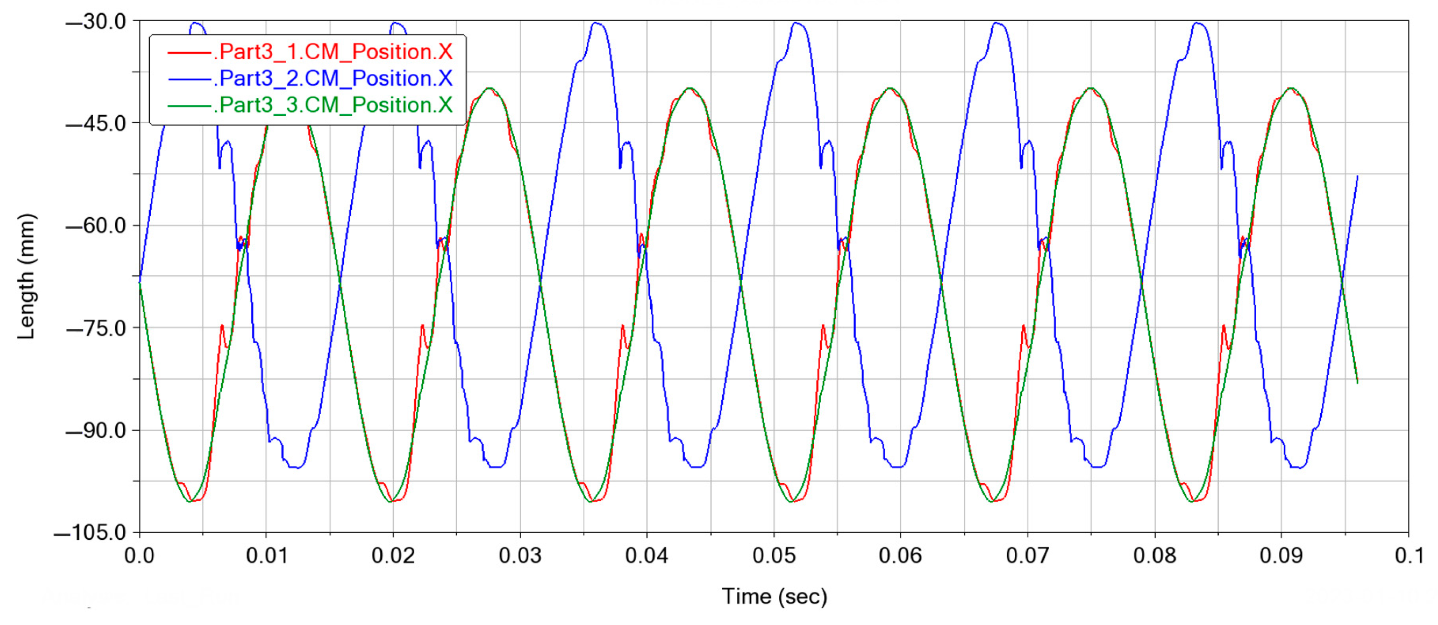
Figure 16.
Engine connecting rod speed curve.
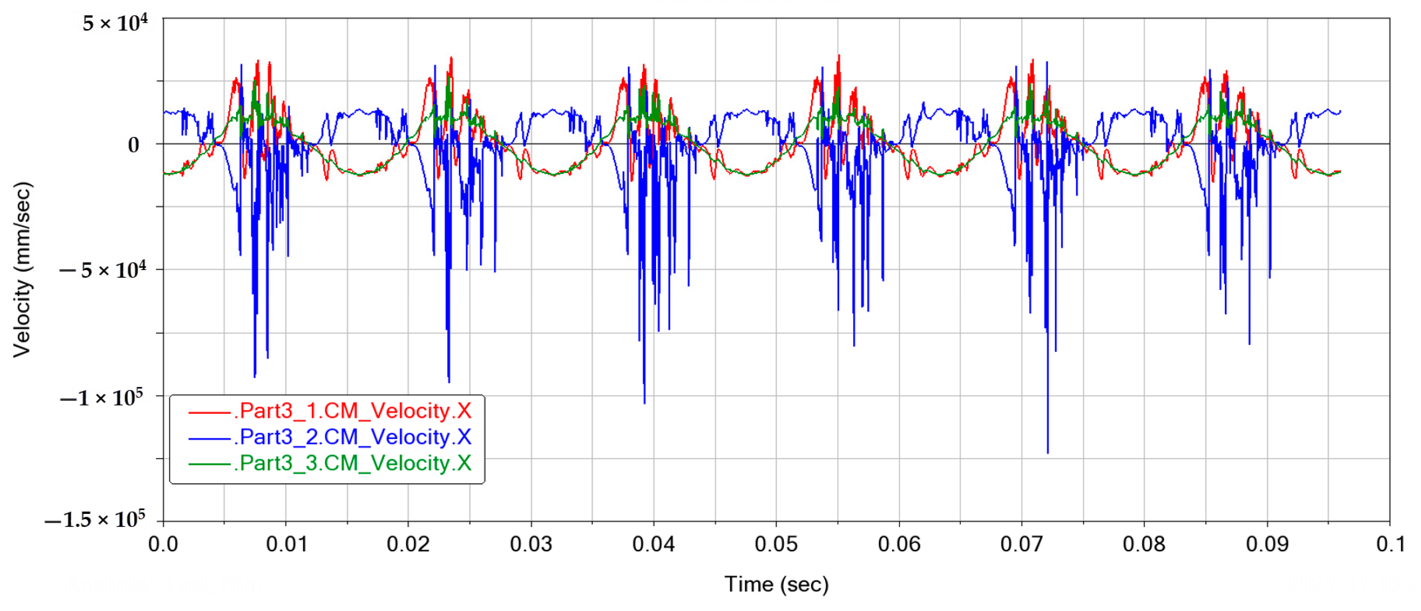
Figure 17.
Engine connecting rod acceleration curve.

Figure 18.
The distribution of forces.

Figure 19.
First crank pin tangential (Y)/diameter (X) direction force curve.
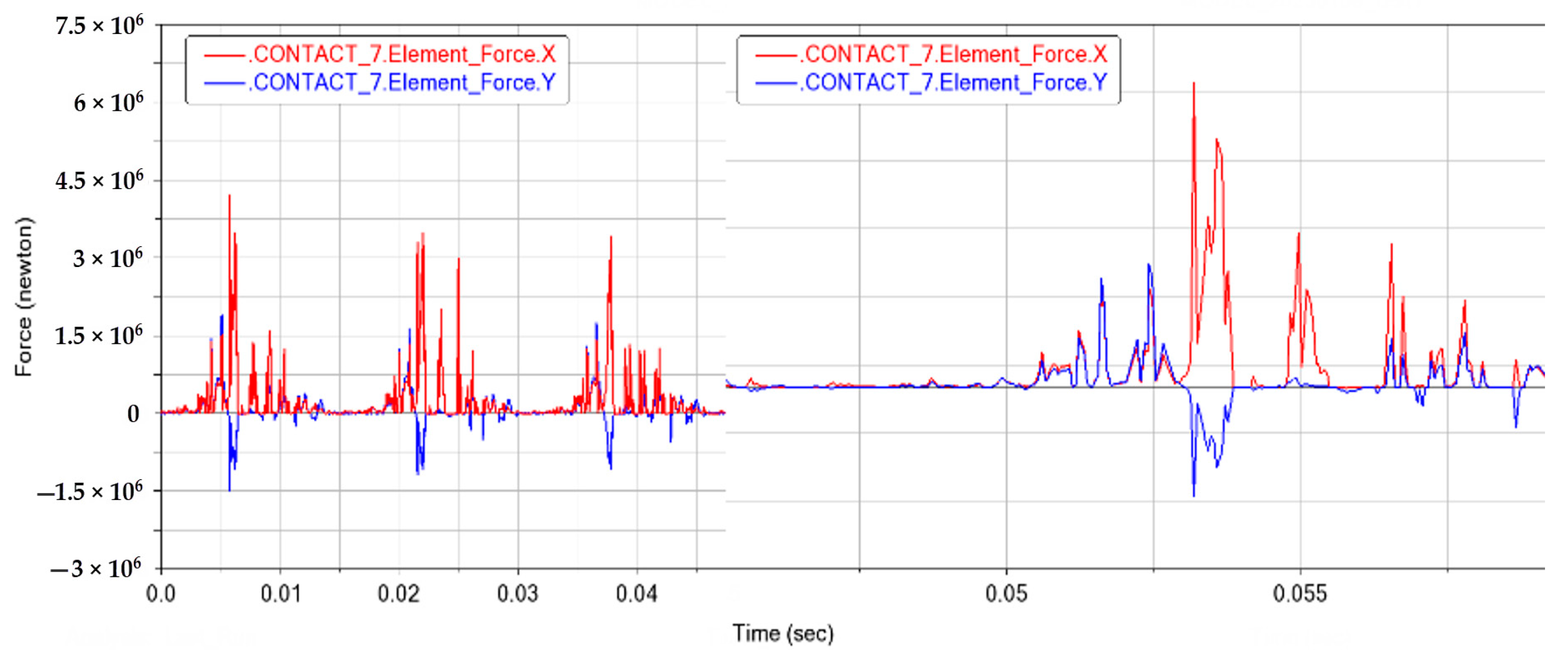
Figure 20.
Second crank pin tangent (Y)/diameter (X) direction force curve.
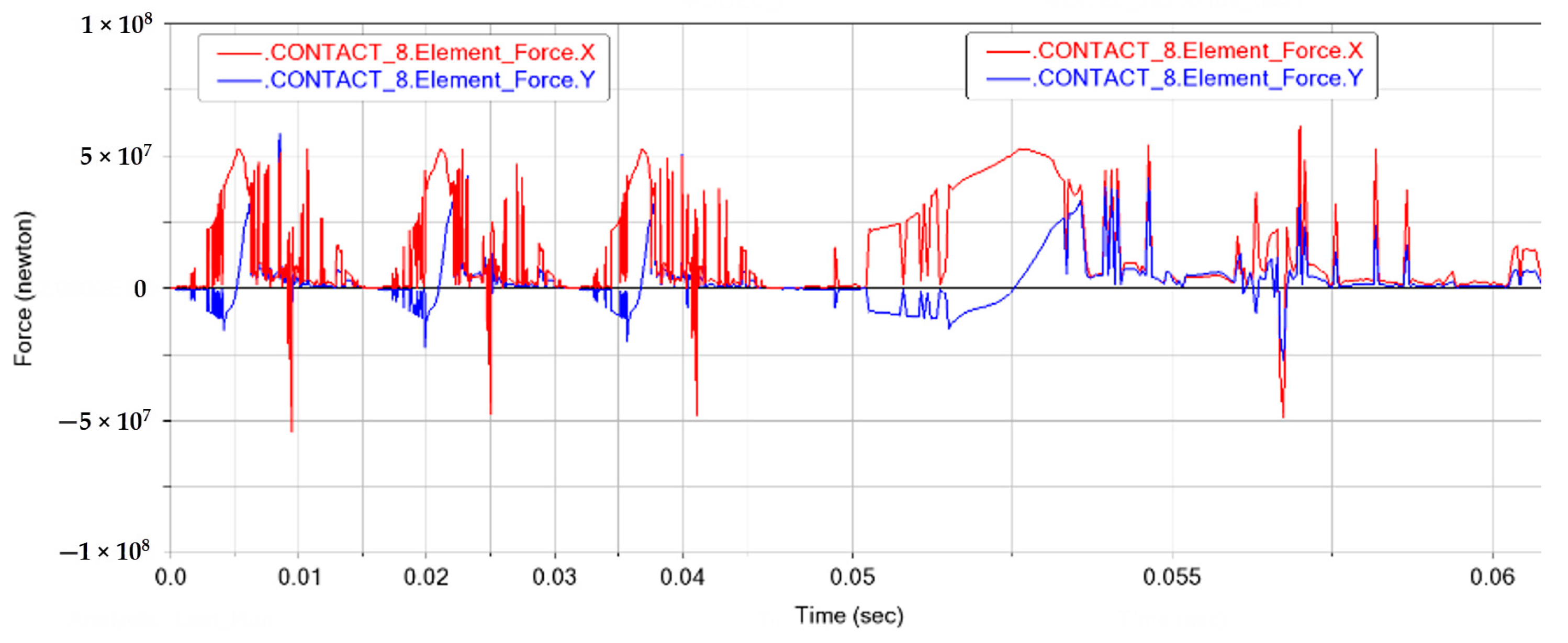
Figure 21.
Third crank pin tangential (Y)/diameter (X) direction force curve.
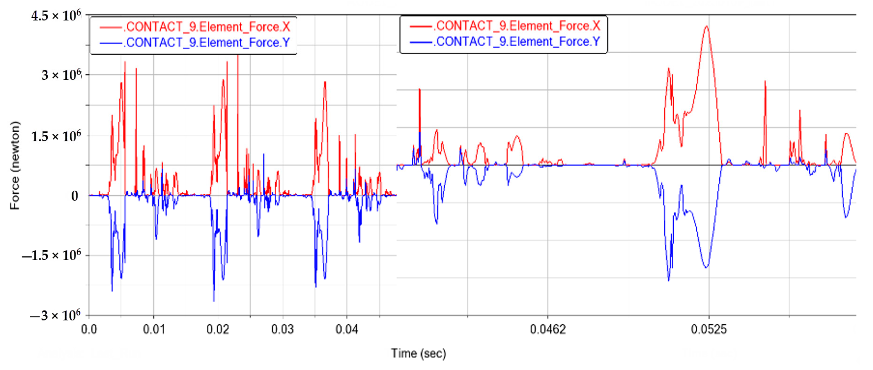
Figure 22.
Maximum stress state.
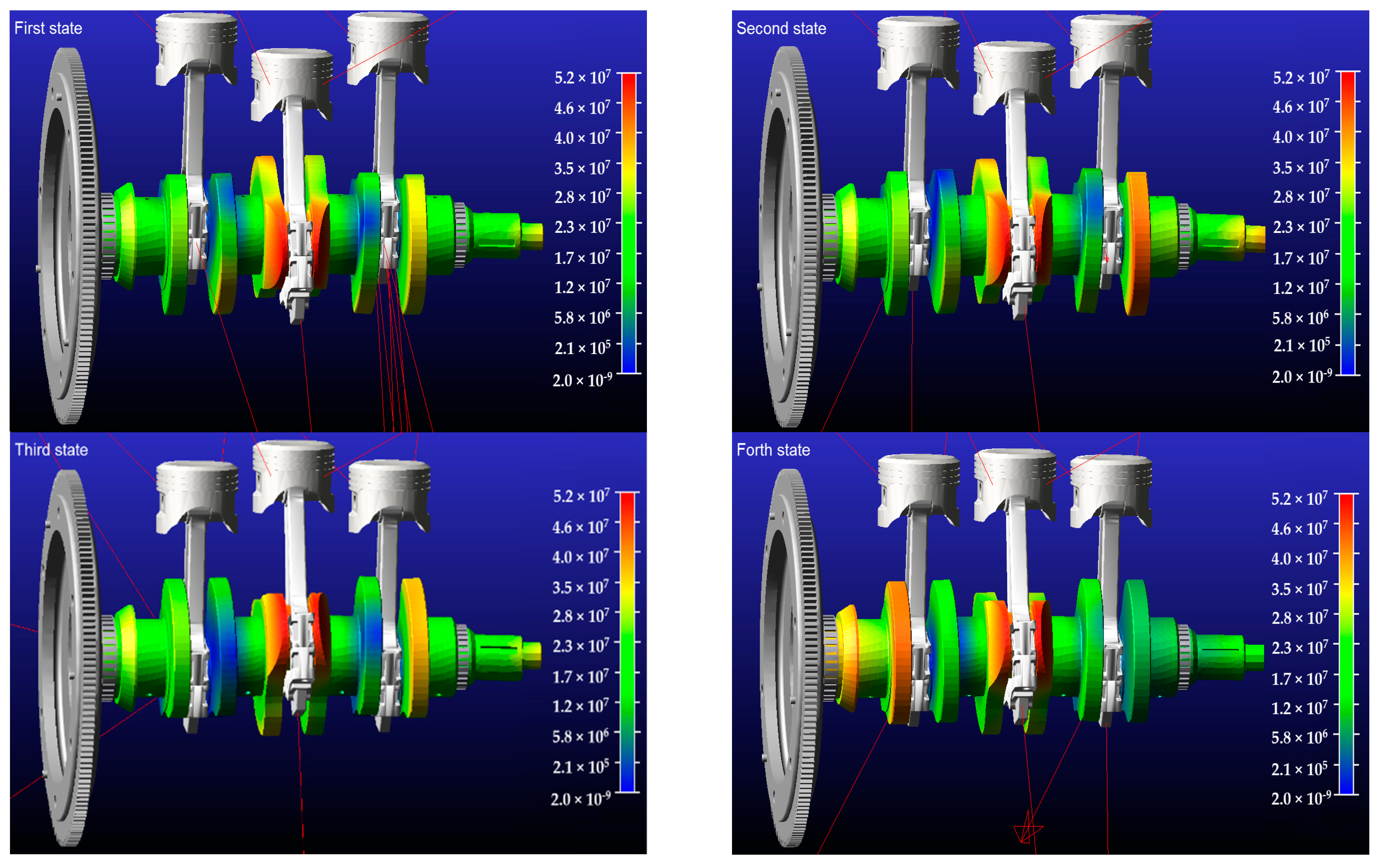
Figure 23.
First piston pin force curve.

Figure 24.
Second piston pin force curve.
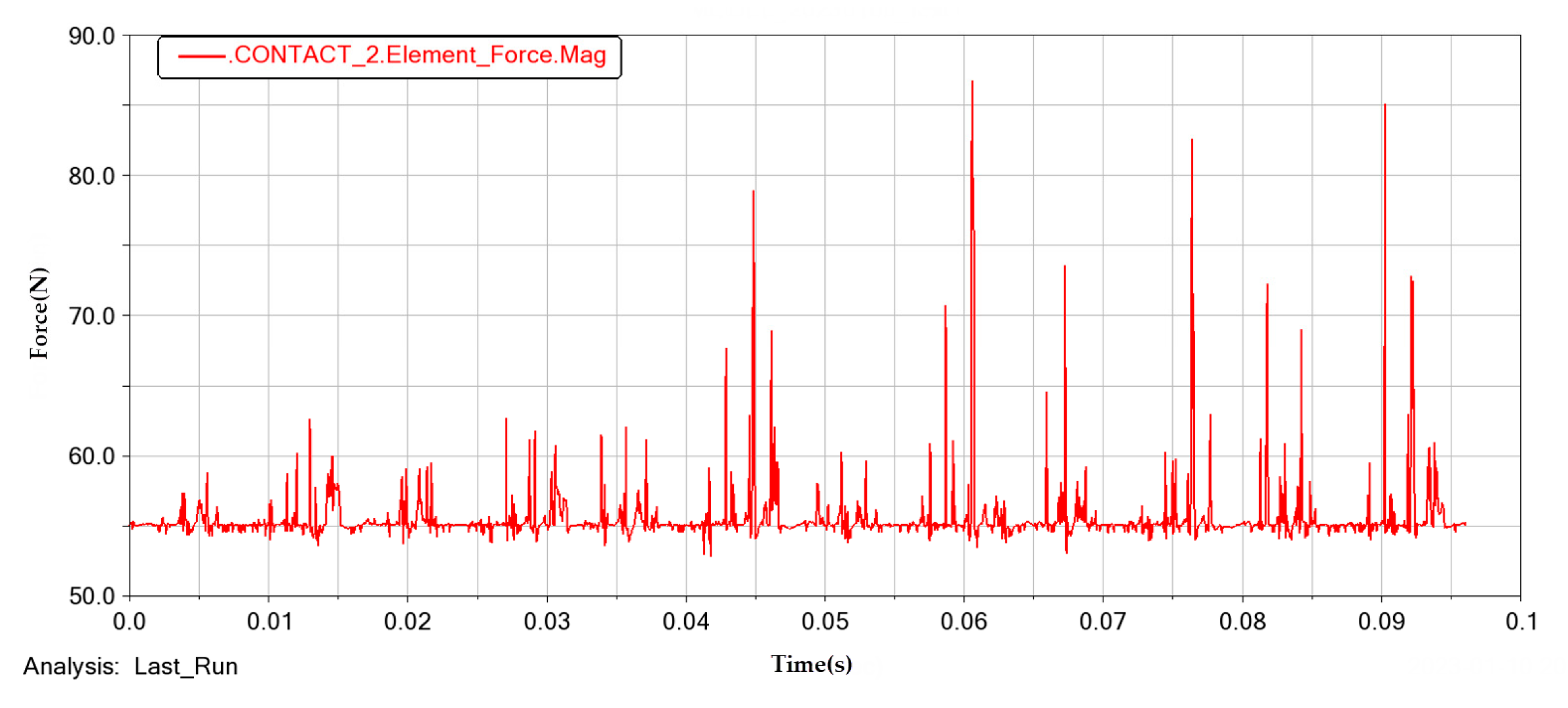
Figure 25.
Third piston pin force curve.
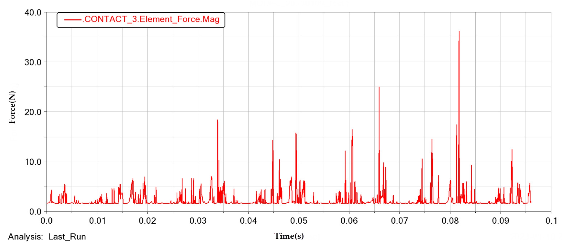
Figure 26.
Test point arrangement.

Figure 27.
Free end torsional vibration at a running speed of 3800 r/min.
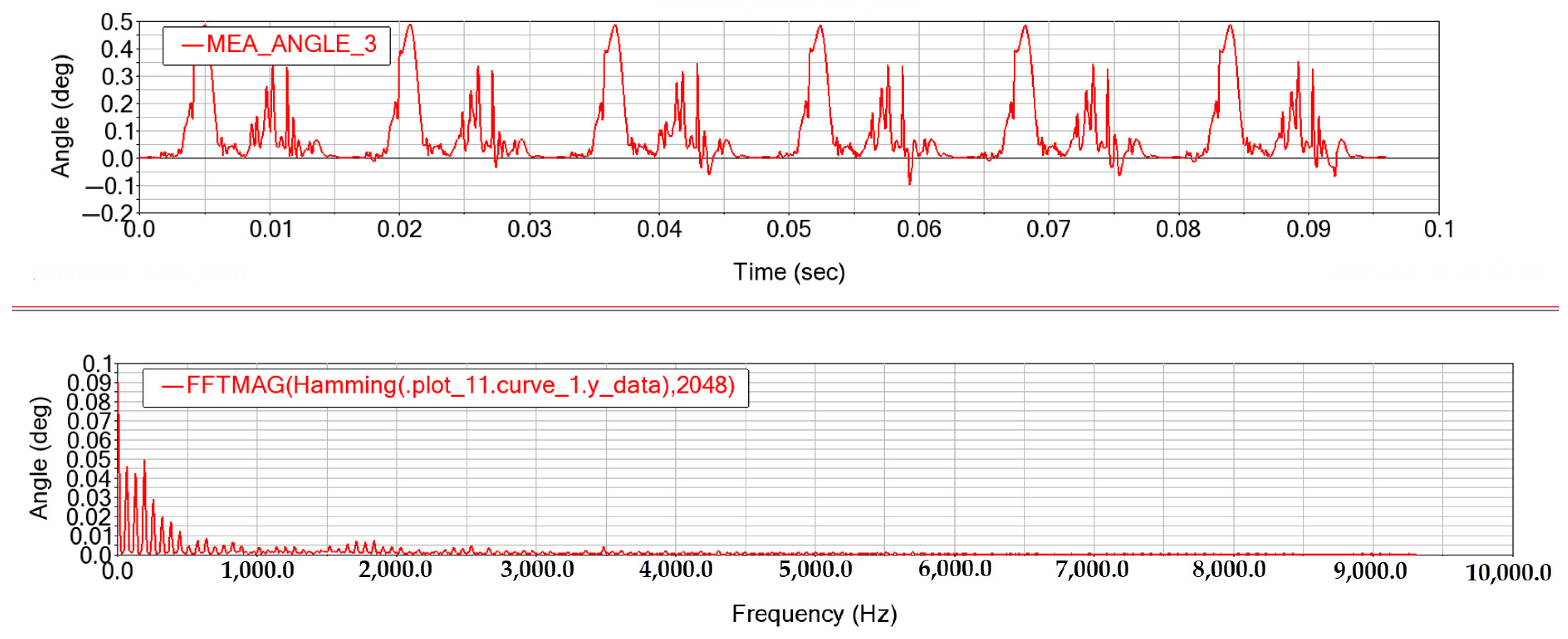
Figure 28.
Torsional vibration of the first crank.

Figure 29.
Torsional vibration of the second crank.

Figure 30.
Torsional vibration of the third crank.
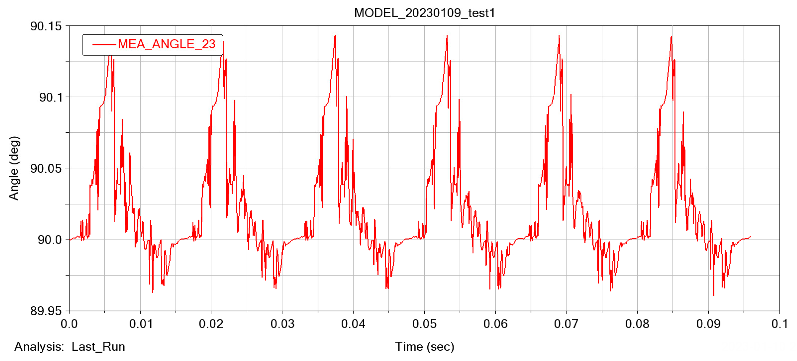
Figure 31.
The 1400 r/min free end torsional vibration.

Figure 32.
The 2600 r/min free end torsional vibration.

Table 1.
Symbolic charts used in Equation (1).
| Symbol | Corresponding Meaning |
|---|---|
| The contact stress on the crankshaft | |
| The combined force applied to the crankshaft | |
| The idealized rectangular contact surface length | |
| The idealized rectangular contact surface width | |
| Poisson’s ratio of material 1 | |
| Poisson’s ratio of material 2 | |
| The modulus of elasticity of material 1 | |
| The modulus of elasticity of material 2 |
Table 2.
Grid independence test.
| Name | Unit Size | Grid Nodes | Grid Cells | Average Mass | Average Deformation |
|---|---|---|---|---|---|
| DP 0 | 1 | 4,956,547 | 3,400,246 | 0.827769 | 7.544466 |
| DP 1 | 1.5 | 1,830,357 | 1,228,602 | 0.814675 | 7.576838 |
| DP 2 | 2 | 1,006,786 | 673,009 | 0.815887 | 7.655221 |
| DP 3 | 2.5 | 606,452 | 399,819 | 0.805338 | 7.814621 |
| DP 4 | 3 | 395,230 | 257,287 | 0.795004 | 7.758828 |
| DP 5 | 3.5 | 291,525 | 188,933 | 0.790261 | 7.478033 |
| DP 6 | 4 | 219,903 | 140,967 | 0.773641 | 7.476684 |
| DP 7 | 4.5 | 167,588 | 106,517 | 0.766163 | 7.474908 |
| DP 8 | 4.8 | 149,001 | 94,094 | 0.746741 | 7.476052 |
| DP 9 | 6 | 109,232 | 64,782 | 0.741255 | 7.342311 |
| DP 10 | 8 | 46,893 | 28,300 | 0.734225 | 7.162736 |
Table 3.
Intrinsic frequency in the different modes.
| Mode | 7 | 8 | 9 | 10 | 11 | 12 |
|---|---|---|---|---|---|---|
| Inherent frequency | 850.23 | 1083.3 | 1773.1 | 1785.8 | 1809.8 | 2544.3 |
| 13 | 14 | 15 | 16 | 17 | 18 | |
| Inherent frequency | 3164.5 | 3840.3 | 3982.4 | 5013.3 | 5312.2 | 5750.4 |
| 19 | 20 | 21 | 22 | 23 | 24 | |
| Inherent frequency | 5785.3 | 6009.4 | 6287.9 | 6671.3 | 6905.2 | 7094.5 |
| 25 | 26 | 27 | 28 | 29 | 30 | |
| Inherent frequency | 7469.8 | 7559.3 | 7605.5 | 7615.4 | 8489.1 | 8868.1 |
Table 4.
Material parameters of each component of the shaft system.
| Serial Number | Parts | Material Name | Modulus of Elasticity (Gpa) | Poisson’s Ratio | Material Density (kg/m3) |
|---|---|---|---|---|---|
| 1 | Crankshaft | 45 gauge steel | 2.06 | 0.3 | 7850 |
| 2 | Connecting rod | 45 Mn manganese steel | 2.1 | 0.28 | 8000 |
| 3 | Piston | Eutectic aluminum alloy | 1.23 | 0.33 | 4650 |
| 4 | Piston pin | 15 Cr chromium steel | 2.12 | 0.284 | 7800 |
| 5 | Flywheel | Ductile iron | - | - | 7200 |
Table 5.
Constraint relationship of each component of the shaft system.
| Serial Number | Parts 1 | Part 2 | Constraint Name |
|---|---|---|---|
| 1 | Cylindrical roller bearings | Crankshaft | Rotating sub |
| 2 | Flywheel | Crankshaft | Fixed sub |
| 3 | Connecting rod (big end) | Crankshaft | Rotating sub |
| 4 | Piston pin | Connecting rod (small end) | Rotating sub |
| 5 | Piston | Piston pin | Rotating sub |
| 6 | Piston | - | Panning |
Disclaimer/Publisher’s Note: The statements, opinions and data contained in all publications are solely those of the individual author(s) and contributor(s) and not of MDPI and/or the editor(s). MDPI and/or the editor(s) disclaim responsibility for any injury to people or property resulting from any ideas, methods, instructions or products referred to in the content. |
© 2023 by the authors. Licensee MDPI, Basel, Switzerland. This article is an open access article distributed under the terms and conditions of the Creative Commons Attribution (CC BY) license (https://creativecommons.org/licenses/by/4.0/).
Share and Cite
MDPI and ACS Style
Zhang, X.; Zheng, L. Investigation on the Dynamics of a Flexible Multi-Body System of a Three-Cylinder Gasoline Engine Crankshaft. Processes 2023, 11, 1248. https://doi.org/10.3390/pr11041248
AMA Style
Zhang X, Zheng L. Investigation on the Dynamics of a Flexible Multi-Body System of a Three-Cylinder Gasoline Engine Crankshaft. Processes. 2023; 11(4):1248. https://doi.org/10.3390/pr11041248
Chicago/Turabian StyleZhang, Xiao, and Lu Zheng. 2023. "Investigation on the Dynamics of a Flexible Multi-Body System of a Three-Cylinder Gasoline Engine Crankshaft" Processes 11, no. 4: 1248. https://doi.org/10.3390/pr11041248
Note that from the first issue of 2016, this journal uses article numbers instead of page numbers. See further details here.