
Thermal-Mechanical Analysis of a Metro Station’s Concrete Structure

1
Guizhou Communications Polytechnic, Guiyang 551400, China
2
School of Civil Engineering and Architecture, Xi’an University of Technology, Xi’an 710048, China
3
Sinohydro Bureau 3 Co., Ltd., Xi’an 710024, China
4
Guizhou Hongxinda High Science & Technology Co., Ltd., Guiyang 550014, China
*
Author to whom correspondence should be addressed.
Processes 2023, 11(4), 1124; https://doi.org/10.3390/pr11041124
Submission received: 31 January 2023
/
Revised: 28 March 2023
/
Accepted: 4 April 2023
/
Published: 5 April 2023
(This article belongs to the Special Issue Composite Materials Processing, Modeling and Simulation)
Abstract
:The problem of temperature variation in mass concrete construction is a crucial problem in civil engineering. The problems of the temperature field, damaged areas, and the cracking of the structure during the construction process of concrete pouring are analyzed in this paper. An elastic and damaged constitutive model for concrete and a fully coupled analysis method for analyzing the temperature-stress field was proposed to simulate and predict the construction process of a concrete structure in a metro station. The influence of different concrete compositions and material properties was not taken into account in this study. The results show that the temperature-stress complete coupling analysis method can be applied to the calculation and analysis of cracking in a concrete structure that is caused by internal temperature variations during the pouring process of complex concrete structures. An efficient method and research approach is proposed by this study to analyze the damage and cracking issues caused by temperature changes during the pouring process of concrete structures in metro stations. The area and extent of the damage and cracking during the construction can be predicted and evaluated, and a reference for metro station construction and operation is proposed.
1. Introduction
The metro station is one of the most important portions of the construction of underground rail transit [1]. It is expensive and difficult to renovate and restore the integrity of the structure due to the internal and surface cracking of concrete structures. For mass concrete, the main factor affecting concrete cracking is temperature change. The temperature change mainly generates concrete temperature cracks during construction or operation periods. Thermal stress will be generated inside the concrete structure due to the temperature difference and the deformation limitation during the metro station construction. The cracks may occur when the structure’s internal tensile stress exceeds the concrete material’s tensile limit [2,3]. Water seepage can easily occur when the concrete structure of the metro station is cracked, which leads to the steel bar corrosion and reduces the reinforced concrete’s strength, thus endangering the operation safety of the metro station and affecting the service life of the concrete. The damage and cracks of concrete structures in subway stations are also affected by many factors, such as the distribution of the temperature field and the constraints of the foundation, as well as the constant change in concrete thermodynamic properties in the construction process. Cracks may also appear during the operation period of the metro station, endangering the safe operation of subway stations [4]. Figure 1 shows a crack in the concrete structure of a metro station. Studying the temperature-stress field caused by heat generation in the concrete pouring process and the corresponding treatment measures are necessary.
Many scholars have studied the temperature stress of mass concrete [3]. Hydration reactions and heat release will occur during the solidification process of the mass concrete; however, heat dissipation is difficult and slow. The heat and temperature of mass concrete structures increase with the increase in cement content in the process of pouring. Moreover, the mass concrete structure is prone to damage and cracks due to the rapid rise in the internal temperature of mass concrete, which seriously affects the durability and safety of the structure. The rise and fall of the internal temperature of the mass concrete structure will cause the expansion and contraction of the concrete, and tensile stress will be generated during the pouring period of concrete, causing concrete cracking, which may continue to appear in the future. The influence of the temperature shrinkage stress of mass concrete on cracking and leakage was analyzed, and the calculation formula of temperature shrinkage stress, crack spacing, and crack width was obtained [5]. The calculation results of an engineering example demonstrate the feasibility of the proposed method. The temperature field and the tensile or compressive stress of a typical dam section of a hydropower station were calculated at different time points during the pouring period of concrete by taking the actual materials and cooling measures into consideration [6,7]. The study results showed that the increment in concrete strength under given conditions is much smaller than the actual situation. If no obvious temperature stress cracks appear after long-term observations after concrete placement, construction should progress according to expectations. The results are of great significance in further predicting the concrete temperature over different periods and studying the effect of temperature control measures. By taking the initial conditions, thermal parameters, boundary conditions, and the influence of reinforcement on the temperature stress of concrete into account, a thermodynamic model was established by researchers [8,9,10]. The effects of environmental factors on the peak temperature, temperature fluctuation amplitude, and maximum temperature stress of massive concrete were analyzed via in situ observations and numerical methods. The temperature of concrete will reduce with wind speed increases, but the causes of leaks and cracks in the side walls of metro stations will also increase. The prevention of leakage in the side walls can be obtained from the aspects of concrete forming conditions, the heat of hydration, and the seepage treatment of the side walls. This method better controls the generation of cracks in the side walls of metro stations [11,12,13]. Many researchers used a numerical method to establish a three-dimensional stress field–temperature field coupling mechanical model for the pouring process of mass concrete structures [14]. The thermal stress–strain relationship at different locations was obtained by comparing it with the monitoring data, offering suggestions for further construction. The variation rule of an early temperature field and early shrinkage of a metro station floor was analyzed via experiments and the finite element method [15]. The optimized anti-crack measures for the floor in the early stages were also studied by researchers [16].
Concrete damage problems are usually analyzed and studied using the elastoplastic and damaged constitutive model. The sequential coupling method is a common analytical method for the problem of temperature stresses on mass concrete. The temperature field is solved first; then, the stress field is solved by applying the volume load to the model. However, the numerical method requires iterative calculation; it is not easy to converge the analysis of coupled field problems [17,18]. The fully coupled analysis method (FCAM) of the temperature and stress fields and a numerical method are used in this paper to analyze the temperature and stress field simultaneously; the damaged and cracked area of a concrete structure in a metro station during its construction period was calculated and determined. By determining the damage caused by temperature stress, the accessible cracking area of the concrete structure of the metro station can be predicted, and a reference for metro station construction and operation is proposed.
2. Methods and Theories
2.1. Theory of Concrete Temperature Field Analysis
The thermal cracking of concrete in the process of pouring belongs to the thermal-mechanical coupling problem, in which the thermal part is the transient heat conduction problem, and the damage or fracture of the concrete is the mechanical problem. Generally, the finite element method (FEM) and other numerical methods are used to calculate and analyze the thermal-mechanical problem of the concrete structure. In this paper, the elastic damaged constitutive model and thermo-mechanical coupling method of FCAM are used to study the damage and fracture caused by temperature stress. The heat of hydration and the temperature variation in the concrete structure over time both belong to the unstable temperature field T = T(X, Y, Z, τ). The heat conduction equation of the three-dimensional unstable temperature field of concrete can be formulated as follows:
By taking the action of the hydration heat of cement into account, the temperature rising rate of the concrete structure under adiabatic conditions is as follows:
Therefore, the heat conduction equation can be rewritten as:
where T is the temperature of concrete (°C); α is the temperature conductivity coefficient of concrete (m2·h); τ is the age of concrete (h); θ is the adiabatic temperature rise in the concrete (°C); Q is a unit of time: the heat released per unit of cement (kJ/(m3·d)); c is the specific heat (kJ/(kg·°C)); ρ is the density (kg/m3); W is the cement dosage (kg); q is the heat of hydration of the cement (kJ/kg); λ is the thermal conductivity of concrete; β is the equivalent heat exchange coefficient of the concrete surface (kJ/m∙h∙°C); Ta indicates the ambient temperature (°C). At the same time, in general, the initial temperature is considered to be a constant: T = T(x, y, z, 0) == constant, and the temperature field T = T(x, y, z, τ) also needs to satisfy the following five boundary conditions:
- (1)
- Initial condition of concrete structure: T(x, y, z, τ) = T0(x, y, z);
- (2)
- Concrete surface temperature is a function of time, i.e., T(x, y, z, τ) = Tτ;
- (3)
- The heat flux of the concrete surface is a known function of time, i.e.,
- (4)
- The surface heat flow of the concrete is proportional to the difference between the surface temperature of the concrete and the air temperature, i.e.,
- (5)
- The temperature and heat flow on the contact surface is continuous when the contact between different solids is under complete closure, i.e., T1 = T2,
2.2. Damaged Constitutive Relationship for Concrete
The strength and constitutive relationship of concrete materials have been studied for a long time. The strength of concrete, which belongs to quasi-brittle materials, is sensitive to the damage of internal microcracks. Therefore, the damage due to internally microcracked concrete is also a key factor in concrete structure construction. A damaged constitutive relationship suit for quasi-brittle materials, e.g., concrete, was established and imported in the FEM code of ABAQUS by Ma [19,20]. The linear elasticity and damaged constitutive relationship can be expressed in the following simplified form:
where is the initial undamaged material matrix; is the material matrix after damage; d is the damage variable; is the effective stress, and ε is the strain matrix. The value of the damage variable d ranges from 0 (undamaged material) to 1(completely damaged material). Damage is associated with the failure mechanism of concrete (cracking and crushing), thus resulting in a reduction in elastic stiffness. In the context of scalar damage, stiffness degradation is isotropic and characterized by the damage variable d. Following the general concept of continuous damage mechanics, Cauchy stresses are related to the effective stresses by scalar degradation relations. Damage variable d can be determined by the damage evolution equation as follows:
where is the equivalent strain and can be calculated by the following equation:
where ε0 is the initial damage threshold, and εu is the failure strain. εmax is the maximum tensile or compressive strain. εmax can be evaluated from the incremental form of the maximum principal strain ε1 in tension and minimum principal strain ε3 in compression. The parameter a is the main control coefficient for the damage evolution equation. The value of the equivalent strain cannot be reduced. Assuming that the value of parameter a is different, the relationship between the damage variable d and equivalent strain in the damage evolution process is shown in Figure 2.
The stress state weight function r(σ) determines the proportions of tensile damage dt and compressive damage dc. The damage variable d is determined by dt, dc, and r(σ). The damage variables dt and dc can predict the failure mechanisms of cracking (tension damage) and crushing (compression damage), respectively. Therefore, the formula for damage degradation variable d can be expressed as follows:
where the stress state weight function r(σ) = 1 when all of the principal stresses σi (σ1, σ2, σ3) are positive; r(σ) = 0 if σi are negative; <·> are the Macauley parentheses (e.g., <x> = (|x|+x)/2). Through the secondary development interface, the concrete constitutive model is programmed as a subroutine in ABAQUS code. The thermal-mechanical damage constitutive model of concrete was written in FORTRAN code as a user subroutine and loaded into the FEM code ABAQUS through the subroutine interface UMATHT. The secondary development interface of ABAQUS consists of UMATHT, FILM, UMAT, and SPRINC subroutines [21]. In this paper, UMATHT is used to define the internal heat generation, thermal conductivity, and specific heat of the concrete. The FILM subroutine is used to simulate the third boundary condition of the temperature field. The UMAT subroutine is used to simulate the variation in the elastic modulus, tensile strength, compressive strength, and damage definition. The stress renewal function, etc., and the principal stresses and strains are calculated via the SPRINC subroutine [22].
3. Calculation and Analysis
3.1. Engineering Background
The analysis of heat generation, thermal stress, and cracking during the concrete pouring and construction process belongs to the thermo-mechanical coupling problem. The different concrete compositions, e.g., aggregates, cement, additives, and admixtures, have a significant influence on the heat generation, thermal stress, and cracking of concrete structures [5]. However, when considering the cost, process, and technology of engineering construction, thermal stress, and temperature control technology, e.g., cooling technology, is widely used [23,24]. The influence of different concrete compositions, e.g., aggregates, cement, additives, and admixtures, were not taken into account in this study. The thermal and mechanical properties of concrete were tested and detected by the engineers of the Xi’an Metro Line 2 project. Numerical methods (i.e., finite element method) were widely used to solve and analyze concrete damage problems using the elastoplastic and damaged constitutive models. In this paper, a linear elasticity and damaged constitutive model and a thermo-mechanical method using FCAM were used to study the damage and fracture distribution of the concrete metro station caused by temperature stress. The purpose of this paper is to provide a simple method and efficient research approach for analyzing the damage and cracking caused by temperature variations during the pouring of concrete structures in the metro station. Multifield coupling and a typical section of the concrete structure of a metro station were used to analyze the temperature field and stress field of the concrete structure of a metro station during the construction period and to find the most vulnerable crack location in the metro station, with the aim of reducing or avoiding crack generation in concrete.
A metro station on the northern extension line of Metro Line 2 in Xi’an was used in this paper as the engineering case. The northern section of Line 2 is close to a river (Wei River). The foundation’s bottom layer is complex, and the groundwater level is high, so it is unsuited for crack resistance in its concrete segments. Groundwater is slightly corrosive to concrete structures and is slightly corrosive to the rebar in reinforced concrete structures in alternating wet and dry environments. The groundwater depth in this area is about 10–15 m. The annual groundwater level variation is about 1–3 m. The lateral runoff and atmospheric precipitation influence the recharge of the groundwater. The discharge of the groundwater includes runoff discharge, artificial extraction, and evaporation.
3.2. FEM Model
The problem of thermal stress and fractures in the concrete of the metro station was analyzed by using the cartesian co-ordinate system. The vertical direction follows the Y-axis and the downward direction is negative. The implicit thermal-mechanical coupling module of the FEM code in ABAQUS was used to analyze the problem. The three-dimensional model of the metro station for numerical analysis is shown in Figure 3. The standard width of a section in the Xi’an Metro Line 2 is 19.9 m; the floor height is 6.5 m, the floor thickness is 0.9 m, the middle plate thickness is 0.4 m, the roof thickness is 0.9 m, and the columns are 0.8 m × 1.3 m. The foundation soil around the metro station has certain constraints and heat exchanges on the concrete metro station; therefore, the three-dimensional mode’s dimensions were determined as 50 m (width) × 33.7 m (depth). The thickness of the backfill of the topsoil is 3.5 m, and the buried depth of the bottom of the metro station is 18.7 m. The coupled temperature-displacement analysis (CTDA) method in ABAQUS adopted the C3D8T element as the element type. There are 156,177 nodes and 145,200 hexahedral elements in this model.
3.3. Boundary Conditions and Construction Simulation
The concrete and soil contact interaction relations are of a fourth boundary condition (solid–solid boundary, with the contact considered). The concrete structure and air contact interaction relations in the metro station are of a third boundary condition (solid–air boundary). A simple support constraint was applied to the bottom surface of the soil, and the displacement in the X- and Y-directions was constrained on two sides, while the displacement in the Z-direction was constrained in the length direction. The surface was treated as a free boundary (as shown in Figure 3b). The construction of the concrete structure of the metro station uses an ABAQUS built-in function model change command for excavation simulations. All the units of the concrete structure of the metro station are removed first. Then, according to the construction pouring order, the concrete structural units of the metro stations are activated successively according to the relevant loading steps until the roof is poured and the soil is backfilled. When calculating the temperature field, the initial temperature of the concrete is an important condition, and the initial temperature of the concrete is the pouring temperature of the concrete. In this simulation, the initial temperature of the concrete is 20 °C. The parameters used in this simulation are shown in Table 1.
The fourth boundary condition (solid–solid boundary) is the contact interaction relation between the concrete structure and the foundation soil in the metro station. The adiabatic boundaries are set to the two sides and the bottom undersides of the foundation. The boundary conditions for the calculation of the stress field include the bottom underside of the foundation, which is constrained by a fixed support, the two sides of the foundation, which are constrained in the horizontal direction, and the other surfaces that are free boundaries. The concrete surface’s heat dissipation coefficient is closely related to wind speed and surface roughness. The heat dissipation coefficient can be calculated via the following expressions:
β = 21.06 + 13.83Va (for rough surface)
β = 18.46 + 13.83Va (for smooth surface, Va is wind speed)
In this study, the surface heat dissipation coefficient was 40 kJ/(m2∙h∙°C). The thermal conductivity of concrete does not change over time; thus, the time for concrete construction pouring will be ignored. The temperature of the local area is fitted by the Fourier function (see Equation (11)), and the fitting result is shown in Figure 4:
3.4. Calculation Results
3.4.1. Temperature Field
The variation law of the temperature and stress fields during concrete pouring was calculated and analyzed. The bottom, top, and sidewall are essential components in the concrete structure of the metro station. The temperature field distribution of the bottom plate, top plate, and side wall of the metro station at the end of the construction period was extracted, as shown in Figure 5. The following results can be obtained from Figure 5: the temperature of the concrete in the bottom plate, roof, and side wall reaches the maximum value at about 40 h to 50 h after pouring, dropping to about 20 °C at about 200 h, and finally approaches ambient temperature. The maximum temperature of the bottom plate, top plate, and sidewall is located in the center of the component because the heat dissipation of the surface is faster than the heat dissipation of the central position. The temperature curves of the bottom plate and the side wall have the same trend. The bottom surface of the bottom plate and the left surface of the side wall are in contact with the soil, where heat dissipation is faster than within the upper surface, and the temperature is lower than the upper surface. The top and bottom surfaces are in contact with the air, so the top and bottom surface temperatures are the same.
3.4.2. Stress Field
Figure 6 shows the temperature and maximum principal stress distribution of the concrete structure of a metro station at the end of the construction period. The maximum principal stress was σ1 = 4.5 MPa at the end of the construction. Different positions of the bottom plate, top plate, and sidewall were selected for analysis. Figure 7 shows that the whole floor was subjected to tensile stress, and stress concentration was generated at the joint of both sides of the floor and the end nodes due to the temperature difference. The stress of the upper surface of the plate is significant due to the loading. As seen in Figure 6, early tensile stress is a process of constant growth. The temperature difference in the middle position is significant, and the tensile stress increases the most.
As can be seen from Figure 7, the temperature stress of the side wall is smaller than that of the bottom plate and top plate; the middle position of the inside side wall is compressed, the upper and lower sides are tensioned, and the stress at the bottom of the side wall is more significant than that at the top due to the gradient effect of earth pressure. As seen in Figure 7, the temperature stress is very low in the early stage and increases more slowly on the floor and roof.
3.4.3. Damage Distribution
The concrete’s compressive characteristics or performance is significantly better than the tensile characteristics, and tensile damage is the main type of concrete damage in the process of pouring. During the concrete pouring process, the most vulnerable areas of concrete could be obtained, and more attention should be paid to tensile damage during construction. In the process of construction, the damaged area of concrete structures in the metro station accumulates over time due to the temperature change over different concrete ages. Figure 8 shows the damage to the concrete structure of the metro station at the end of the construction period. It can be seen from Figure 9 that, from the beginning to the completion of construction, the concrete damage distribution range is vast, and the damage degree of each component is different. The maximum damage value was located at the contact position between the middle plate and the upper and lower columns. The next most damaged area was concentrated near the bottom of the side wall and on both sides of the middle plate. The contact position between the middle plate, the upper and lower columns, and the bottom of the side wall (places with significant damage) was selected for damage analysis. The damage curves recorded by different analysis points are shown in Figure 9.
3.5. Analysis and Discussion
In this paper, the damage and fracture of the concrete metro station induced by the temperature stress were studied using elastic damage and thermal-mechanical FCAM. The following views can be obtained from the calculation results. The temperature of the concrete in the bottom plate, roof, and side wall reaches the maximum value at about 40 h to 50 h after pouring, dropping to about 20 °C at about 200 h, and finally approaches ambient temperature. The maximum temperature of the bottom plate, top plate, and sidewall of the metro station is located in the center of the component; the heat dissipation of the surface is faster than the heat dissipation of the central position. The bottom surface of the bottom plate and the left surface of the side wall are in contact with the soil, where heat dissipation is faster than within the upper surface, and the temperature is lower than the upper surface. The temperature stress of the side wall is smaller than that of the bottom plate and top plate. The middle position of the inside side wall is compressed, the upper and lower sides are tensioned, and the stress at the bottom of the side wall is more significant than at the top due to the gradient effect of earth pressure. The most vulnerable area to concrete cracking can be obtained by comparing the damage value; the damage value increases with time during the process of concrete pouring, and more attention should be paid to the construction period.
During the concrete setting process, the cement and aggregate material will trigger a hydration reaction and release heat. The heat and temperature of massive concrete structures, such as hydroelectric concrete dams, increase with the amount of cement used in the pouring process. There is also a slight increase in heat and temperature during the pouring of concrete structures in metro stations or other examples of underground space engineering. The temperature control of mass concrete has great significance in assuring concrete engineering quality. The FEM code (e.g., MIDAS, ABAQUS) was wildly used to simulate the temperature field of mass concrete in high-rise buildings or constructions [20,24,25]. The simulation and analysis of FEM are feasible as an efficient analysis method for temperature control and management. The existing temperature stress problems of concrete can be extensively analyzed and studied by using the sequential coupling method. This method analyzes the temperature field and stress field separately and identifies the distribution and cracking of concrete cracks only through stress field analysis [26]. In fact, the whole process of heat generation, damage evolution, and cracking during the concrete pouring process cannot be directly predicted via the sequential coupling method. Current studies show that the coupling problem of the temperature and stress field of concrete structures in complex underground spaces can be analyzed efficiently via the elastic damaged constitutive model, FEM, and FCAM for the temperature-stress field [27,28].
4. Conclusions
In this paper, the temperature-stress field and damage cracking caused by the hydration exothermic reaction of concrete during the construction of a concrete structure in a metro station was numerically analyzed using FCAM for the temperature-stress field. The influence of different concrete compositions and their material properties were not taken into account in this study. The following conclusions were obtained:
In this paper, FCAM for the temperature and stress field was used to comprehensively consider the complex boundaries, construction sequences, and other factors, which can simulate and analyze the pouring process of concrete metro station segments effectively and reveal the change in temperature and the temperature stress of metro station concrete. A linear constitutive model for the thermal-mechanical damage of concrete was programmed and imported into FEM code (ABAQUS) using the secondary development interface UMATHT as a user subroutine.
Through calculation and analysis, it can be seen that the damage evolution and crack propagation during concrete pouring is a process that accumulates over time. A reference for the optimization of the design, operation, and risk management of a metro station can be proposed by predicting concrete damage distribution. Moreover, damage distribution is mainly found at the bottom of the side wall, where the board and the column will appear to have significant damage, and attention should be paid to these parts during construction.
Based on the above analysis, the temperature stress will be reduced correspondingly, and the maximum temperature stress occurrence time will be prolonged by adopting thermal insulation measures. Therefore, in the process of metro station construction, thermal insulation measures should be taken as far as possible to reduce the temperature difference between the inside and outside. At the same time, the lowest hydration heat for the cement should be used to reduce the amount of cement and the heat generated via its hydration, and, as far as possible, reduce the temperature of the concrete close to the mold. This would predict and evaluate the distribution of damage and cracking of concrete structures during the construction of a metro station, and act as a reference for the metro station construction and operation.
Author Contributions
Conceptualization, Z.L. and K.J.; methodology and software, W.L.; investigation and data curation, X.R.; writing and editing, Z.M. All authors have read and agreed to the published version of the manuscript.
Funding
The research described in this paper was funded by the project of Guizhou Science & Technology Cooperation Platform Talent (grant number: CXTD [2021]008).
Data Availability Statement
All data, models, and code generated or used during the study appear in the submitted article.
Conflicts of Interest
The authors declare no conflict of interest.
References
- Sun, D.; Zhao, Y.H.; Lu, Q.C. Vulnerability analysis of urban rail transit networks: A case study of Shanghai, China. Sustainability 2015, 7, 6919–6936. [Google Scholar] [CrossRef] [Green Version]
- Qi, F.; Wu, Y.X.; Zhang, W.J. Study on fiber concrete impermeability test and its application in metro station. Adv. Mater. Res. 2011, 261, 280–286. [Google Scholar] [CrossRef]
- Zhu, B.F. Key principles for temperature control of mass concrete. In Thermal Stresses and Temperature Control of Mass Concrete; Elsevier: Amsterdam, The Netherlands, 2014; pp. 469–478. [Google Scholar]
- Dong, Z.; Quan, W.; Ma, X.; Li, X.; Zhou, J. Asymptotic homogenization of effective thermal-elastic properties of concrete considering its three-dimensional mesostructure. Comput. Struct. 2023, 279, 106970. [Google Scholar] [CrossRef]
- Wang, Z.H.; Zhang, L.; Liu, Y.; Liu, Y.Z. Study on temperature control and crack prevention of high-performance slag concrete structure during construction. In Proceedings of the International 2010 Conference on Mechanic Automation and Control Engineering, Wuhan, China, 26–28 June 2010; pp. 1219–1223. [Google Scholar]
- Hariri-Ardebili, M.A.; Seyed-Kolbadi, S.M. Seismic cracking and instability of concrete dams: Smeared crack approach. Eng. Fail. Anal. 2015, 52, 45–60. [Google Scholar] [CrossRef]
- Ghasemi, M.; Zhang, C.; Khorshidi, H.; Zhu, L.; Hsiao, P. Seismic upgrading of existing RC frames with displacement-restraint cable bracing. Eng. Struct. 2023, 282, 115764. [Google Scholar] [CrossRef]
- Qing, W.; Ren, X.D.; Ballarini, R. A multifield model for early-age massive concrete structure: Hydration, damage, and creep. J. Eng. Mech. 2020, 146, 04020115. [Google Scholar]
- Wang, G.Q.; He, M.; Zhou, C.J.; Xie, W.; Liu, X.; Chen, J.; Liu, H.; Lei, B.; Zhang, M. Temperature and temperature stress analysis in mass concrete under cold environments of strong wind and large diurnal temperature range. Geofluids 2022, 2022, 3064754. [Google Scholar] [CrossRef]
- Xiao, X.; Zhang, H.; Li, Z.; Chen, F.; Rasulo, A. Effect of temperature on the fatigue life assessment of suspension bridge steel deck welds under dynamic vehicle loading. Math. Probl. Eng. 2022, 2022, 7034588. [Google Scholar] [CrossRef]
- Yang, B.G.; He, P.; Peng, G.Y.; Tong, L. Temperature-stress coupling mechanism analysis of one-time pouring mass concrete. Therm. Sci. 2019, 23, 231. [Google Scholar] [CrossRef] [Green Version]
- Al-Saleh, S.A.; Al-Zaid, R.Z. Effects of drying conditions admixtures and specimen size on shrinkage strains. Cem. Concr. Res. 2004, 36, 1985–1991. [Google Scholar] [CrossRef]
- Zhang, W.; Kang, S.; Huang, Y.; Liu, X. Behavior of reinforced concrete beams without stirrups and strengthened with basalt fiber–reinforced polymer sheets. J. Compos. Constr. 2023, 27, 4023007. [Google Scholar] [CrossRef]
- Wu, Y.; Luna, R. Numerical implementation of temperature and creep in mass concrete. Finite Elem. Anal. Des. 2001, 37, 97–106. [Google Scholar] [CrossRef]
- Lan, C.; Lee, M.S.; Seo, T.S. Crack control design due to drying shrinkage in restrained reinforced concrete wall. Struct. Des. Tall Spec. Build. 2013, 22, 1047–1061. [Google Scholar]
- Kovler, K. Testing system for determining the mechanical behavior of early age concrete under restrained and free uniaxial shrinkage. Mater. Struct. 1994, 27, 324–330. [Google Scholar] [CrossRef]
- Lee, J.; Fenves, G.L. Plastic-damage model for cyclic loading of concrete structures. J. Eng. Mech. ASCE 1998, 124, 892–900. [Google Scholar] [CrossRef]
- Zhang, Z.; Liang, G.; Niu, Q.; Wang, F.; Chen, J.; Zhao, B.; Ke, L. A Wiener degradation process with drift-based approach of determining target reliability index of concrete structures. Qual. Reliab. Eng. Int. 2022, 38, 3710–3725. [Google Scholar] [CrossRef]
- Ma, Z.Y.; Dang, F.N.; Li, Y.L.; Cheng, Y.X. Influence of geostress field on dynamic mechanical behavior of intact rock. Arab. J. Geosci. 2021, 14, 78. [Google Scholar] [CrossRef]
- Li, Z.Y.; Ma, Z.Y.; Zhao, B.; Li, D.F.; Jiao, K. Fully Coupled Thermal-mechanical Analysis of Concrete Gravity Arch Dam. In Proceedings of the 8th International Conference on Hydraulic and Civil Engineering (ICHCE): Deep Space Intelligent Development and Utilization Forum, Xi’an, China, 25–27 November 2022; Volume 2022, pp. 856–861. [Google Scholar]
- Dassault Systems Simulia Corp. Abaqus 6.14 Help Documentation; Simulia: Johnston, RI, USA, 2014. [Google Scholar]
- Liu, H.; Chen, Z.; Liu, Y.; Chen, Y.; Du, Y.; Zhou, F. Interfacial debonding detection for CFST structures using an ultrasonic phased array: Application to the Shenzhen SEG building. Mech. Syst. Signal Process. 2023, 192, 110214. [Google Scholar] [CrossRef]
- Zhu, B.F. Precooling and surface cooling of mass concrete. In Thermal Stresses and Temperature Control of Mass Concrete; Elsevier: Amsterdam, The Netherlands, 2014; pp. 401–408. [Google Scholar]
- Zhou, Y.C.; Bai, L.; Yang, S.Y.; Chen, G.T. Simulation Analysis of Mass Concrete Temperature Field. Procedia Earth Planet. Sci. 2012, 5, 5–12. [Google Scholar]
- Wang, M.; Yang, X.; Wang, W. Establishing a 3D aggregates database from X-ray CT scans of bulk concrete. Constr. Build. Mater. 2022, 315, 125740. [Google Scholar] [CrossRef]
- Liu, N.F.; Li, N.; Li, G.F.; Song, Z.P.; Wang, S.J. Method for Evaluating the Equivalent Thermal Conductivity of a Freezing Rock Mass Containing Systematic Fractures. Rock Mech. Rock Eng. 2022, 55, 7333–7355. [Google Scholar] [CrossRef]
- Liu, N.F.; Li, N.; Wang, S.J.; Li, G.F.; Song, Z.P. A fully coupled thermo-hydro-mechanical model for fractured rock masses in cold regions. Cold Reg. Sci. Technol. 2022, 205, 103707. [Google Scholar] [CrossRef]
- Ma, Z.Y.; Dang, F.N.; Liao, H.J. Numerical study of the dynamic compaction of gravel soil ground using the discrete element method. Granul. Matter 2014, 16, 881–889. [Google Scholar] [CrossRef]
Figure 1.
Photograph of the cracked concrete structure in a metro station in Xi’an China.
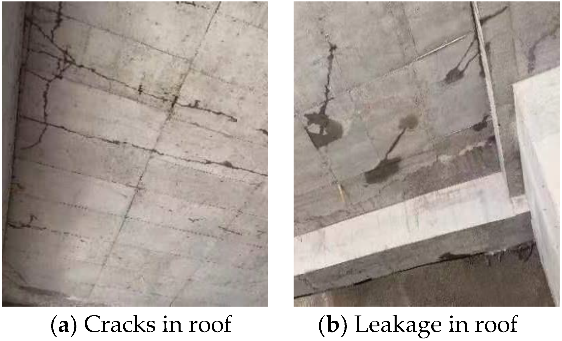
Figure 2.
Curves of damage evolution equation.

Figure 3.
Finite element model of metro station for analysis.
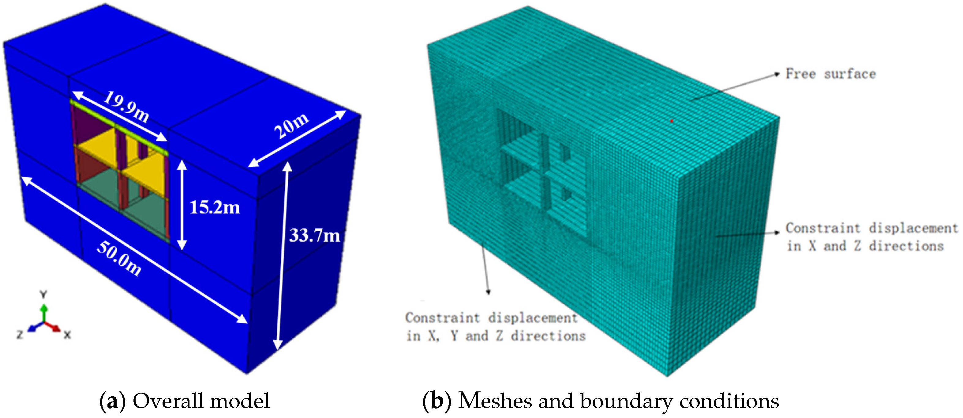
Figure 4.
Comparison between the actual and fitting temperature.
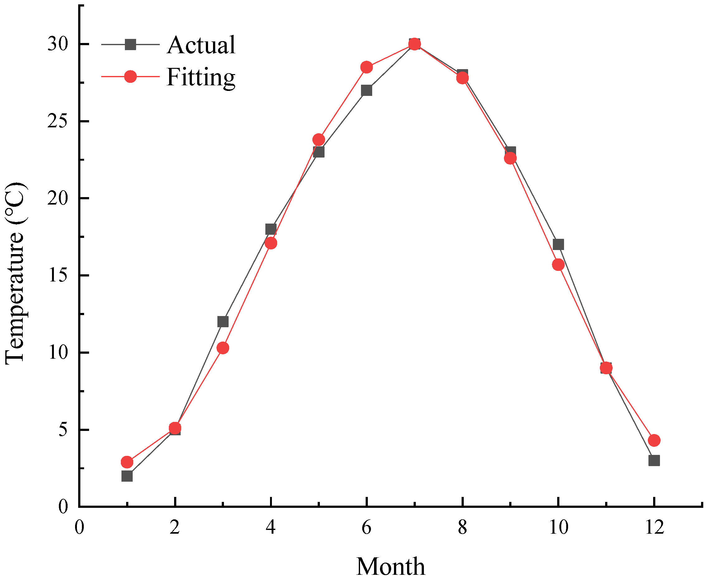
Figure 5.
Temperature of concrete structure of metro station varies with time.
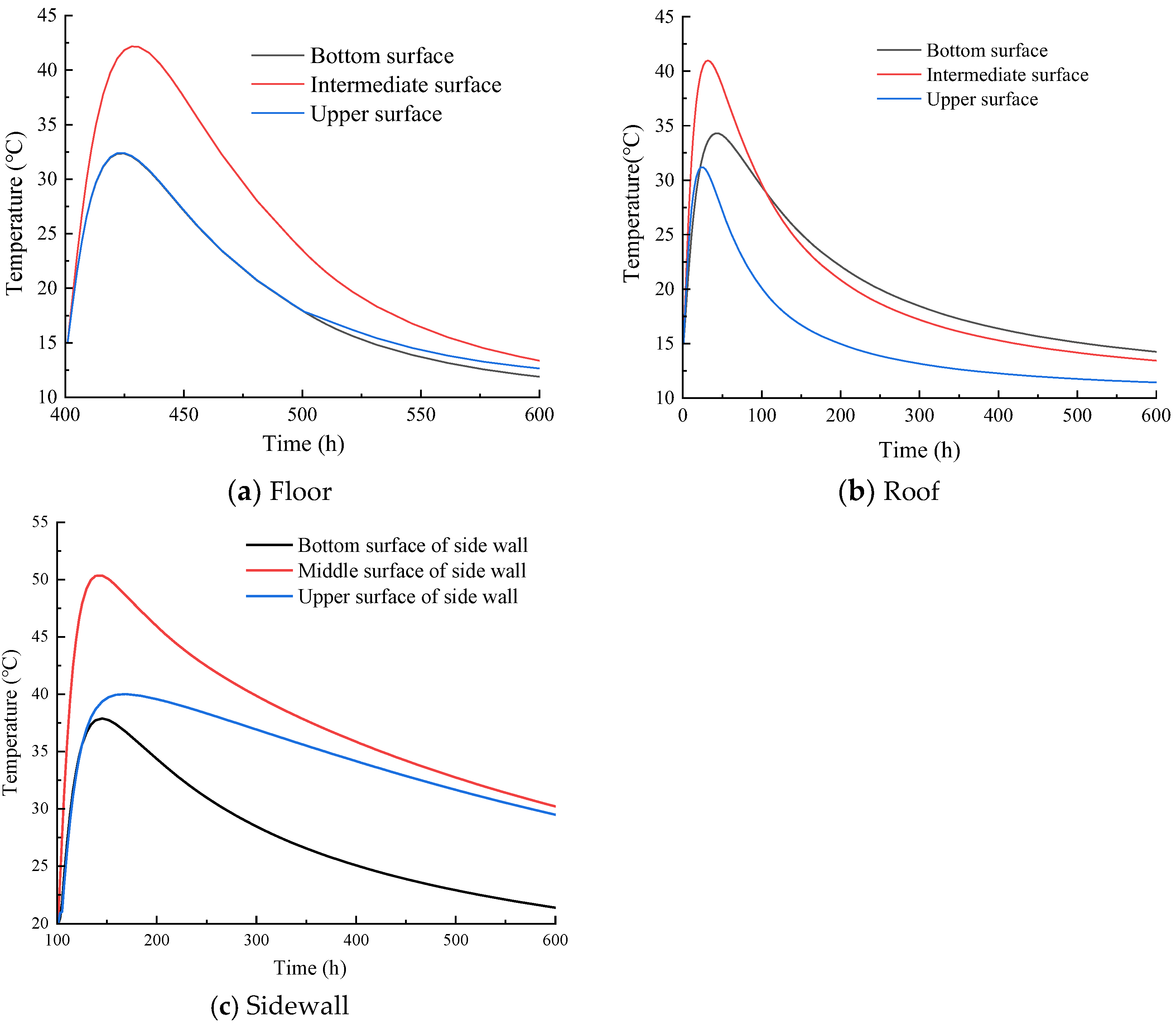
Figure 6.
Temperature and maximum principal stress distribution of a concrete structure in a metro station at the end of the construction period.
Figure 6.
Temperature and maximum principal stress distribution of a concrete structure in a metro station at the end of the construction period.
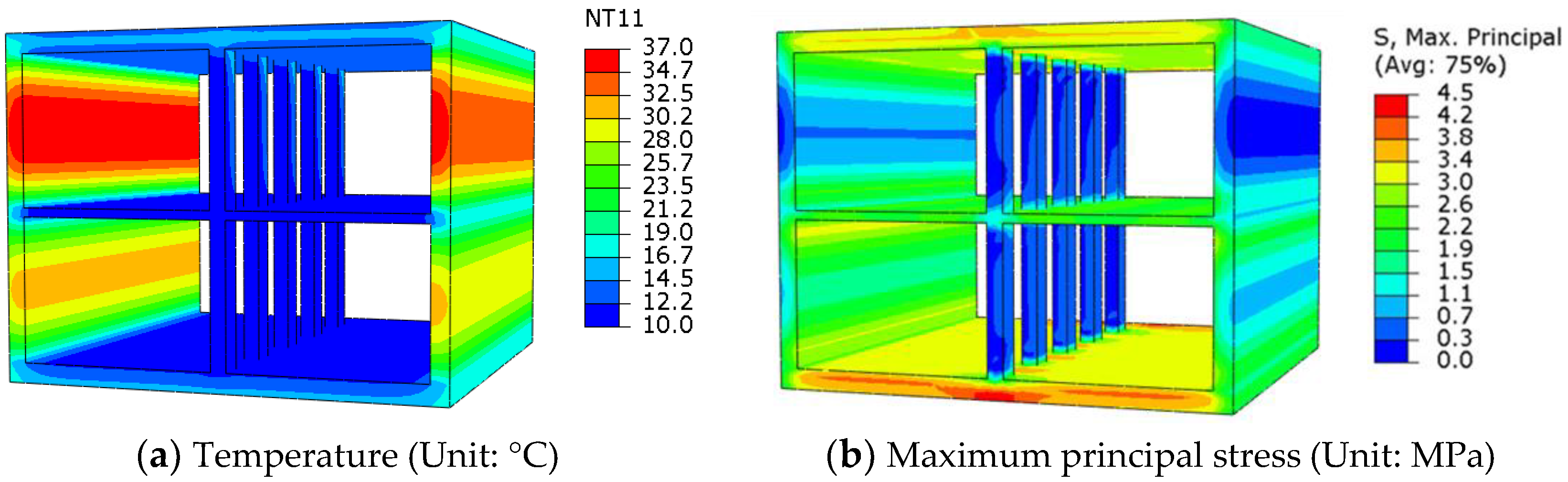
Figure 7.
Maximum principal stress of a concrete structure in a metro station varies with time.

Figure 8.
Damage distribution of side wall after pouring.
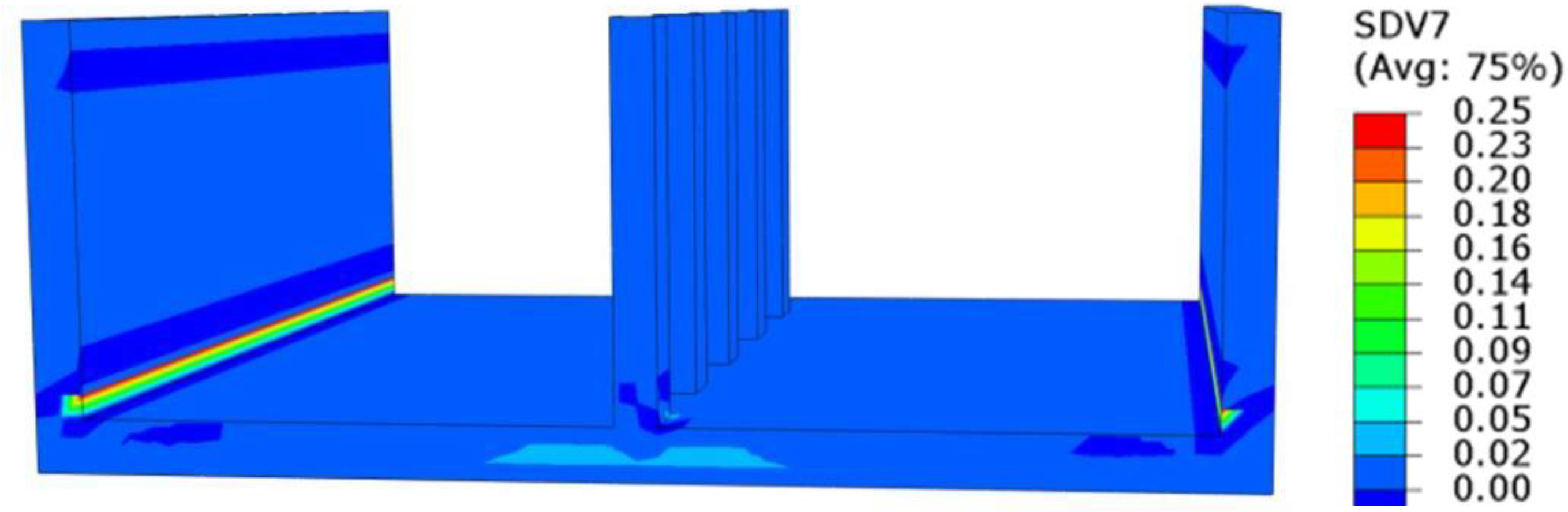
Figure 9.
Damage curves of a concrete structure in a metro station at different analysis points.


Table 1.
Thermal properties of concrete and foundation soil of the metro station.
| Parameters | Concrete (C35) | Foundation Soil |
|---|---|---|
| Specific heat (kJ/kg∙°C) | 0.98 | 0.8 |
| Thermal conductivity (kJ/(m∙h∙°C)) | 9.8 | 7 |
| Coefficient of thermal expansion | 8 × 10⁻⁶ | 1 × 10⁻⁶ |
| Density (kg/m3) | 2400 | 1800 |
| Initial temperature (°C) | 20 | 15 |
| Poisson’s ratio | 0.2 | 0.2 |
Disclaimer/Publisher’s Note: The statements, opinions and data contained in all publications are solely those of the individual author(s) and contributor(s) and not of MDPI and/or the editor(s). MDPI and/or the editor(s) disclaim responsibility for any injury to people or property resulting from any ideas, methods, instructions or products referred to in the content. |
© 2023 by the authors. Licensee MDPI, Basel, Switzerland. This article is an open access article distributed under the terms and conditions of the Creative Commons Attribution (CC BY) license (https://creativecommons.org/licenses/by/4.0/).
Share and Cite
MDPI and ACS Style
Ma, Z.; Li, W.; Li, Z.; Ruan, X.; Jiao, K. Thermal-Mechanical Analysis of a Metro Station’s Concrete Structure. Processes 2023, 11, 1124. https://doi.org/10.3390/pr11041124
AMA Style
Ma Z, Li W, Li Z, Ruan X, Jiao K. Thermal-Mechanical Analysis of a Metro Station’s Concrete Structure. Processes. 2023; 11(4):1124. https://doi.org/10.3390/pr11041124
Chicago/Turabian StyleMa, Zongyuan, Wei Li, Zhaoyu Li, Xuefei Ruan, and Kai Jiao. 2023. "Thermal-Mechanical Analysis of a Metro Station’s Concrete Structure" Processes 11, no. 4: 1124. https://doi.org/10.3390/pr11041124
Note that from the first issue of 2016, this journal uses article numbers instead of page numbers. See further details here.