Article

The Effect of Electro-Induced Multi-Gas Modification on Polymer Substrates’ Surface Structure for Additive Manufacturing

Faculty of Printing Industry, Moscow Polytechnic University, 107023 Moscow, Russia
*
Author to whom correspondence should be addressed.
Processes 2023, 11(3), 774; https://doi.org/10.3390/pr11030774
Submission received: 18 December 2022 / Revised: 17 February 2023 / Accepted: 2 March 2023 / Published: 6 March 2023
(This article belongs to the Section Materials Processes)

Abstract

:
We investigated the effect of electro-induced multi-gas modification (EIMGM) duration on the adhesion and wear resistance of PET and LDPE polymer substrates used in the printing industry. It was found that EIMGM increases the polar component and the complete free surface energy from 26 to 57 mJ/m2 for LDPE and from 37 to 67 mJ/m2 for PET (due to the formation of oxygen-containing groups on the surface of the materials). Although the degree of textural and morphological heterogeneity of the modified LDPE increased more than twice compared to the initial state, it is not still suitable for application as a substrate in extrusion 3D printing. However, for PET, the plasma-chemical modification contributed to a significant increase (~5 times) in filament adhesion to its surface (due to chemical and morphological transformations of the surface layers) which allows for using the FFF technology for additive prototyping on the modified PET-substrates.

1. Introduction

The intensive development of flexible substrate-based printed micro- [1,2] and optoelectronics [3,4] caused a fundamental interest in the high-quality coating of polymer materials [5] with functional conductive [6,7,8,9,10], semi-conductive [11], and dielectric [12] layers. The most popular substrates are large-tonnage and, as a result, widely available hydrophobic polymers (LDPE, PP, PET, etc.) with low free surface energy values in the range of 20–35 mJ/m2 [13]. Since the surface tension of water- and solvent-based inks can reach ~72 mN/m, the free surface energy of the substrates (polymer or composite) must be significantly increased to ensure an acceptable adhesion quality of the functional layers [14].
A lot of chemical modification methods and techniques have been shown to achieve this goal [15,16,17,18,19,20,21,22].
The authors of [23] described the modification techniques of acylation, carboxylation, alkylation, and quaternization in order to improve the water solubility, pH sensitivity, and the targeting of chitosan derivatives (chitosan is an antibacterial bio-polymer material prospect for the drug delivery industry).
The surface modification and synthesis techniques, the basic properties, toxicity issues, and biomedical applications of nanodiamonds (ND) are represented in [24] (the nanodiamonds are novel nanosized carbon building blocks possessing varied fascinating mechanical, chemical, optical, and biological properties, making them significant active moiety carriers for biomedical application).
Another review [25] focused on modifications, introduced in a pre-or post-SELEX manner, that directly or indirectly influence the binding event of the aptamer, resulting in enhanced target binding (the aptamers are short single-stranded DNA or RNA oligonucleotides that can recognize analytes with extraordinary target selectivity and affinity).
The capping of the 3′-end with an inverted deoxythymidine modification was used to increase the stability and resistance of aptamers to 3′-exonuclease in human blood serum [26]. Surface functionalization involves modification of the surface strategies of any compound (NDs) by attaching a variety of functional groups such as hydroxyl, carbonyl, carboxyl, anhydrides, and lactones [27]. Surface functionalization also has been shown to enhance solubility in a variety of polar organic solvents as well as stability (by preventing agglomeration). The chemical technique involves heating nanodiamond powder in air at 400–430 °C so as to eliminate the sp2 carbon impurities which may reduce the chances of agglomeration [28].
In [29], the effectiveness of h-BN surface modification by γ-aminopropyltriethoxysilane and the formation of strong chemical bonds at the polymer matrix/filler interface was proven, ensuring an increase in the physico-mechanical characteristics of epoxy composites, i.e., the bending stress increased by 142%, the bending modulus increased by 52%, strength increased by 53%, the tensile elastic modulus increased by 37%, toughness increased by 400% and the Brinell hardness increased by 96%, compared with an unfilled plasticized epoxy composite.
The surface functionalization with the avidin-biotin conjugation technique also led to gelatin nanofiber immobilization factor growth [30]. Additionally, an example of an inorganic combination that provided mechanical properties improving and induced bone formation was represented in [31]. The PLGA-nanofiber was treated with oxygen plasma on its surface to improve its hydrophilicity and adhesion [32].
The advances in carbon dots (CD) modification with a focus on surface functionalization, element doping, passivation, and nanocomposite formation with metal oxides, transition metal chalcogenides, or graphitic carbon nitrides were represented in [33]. The effects of CD functionalization on photocatalytic properties with the photocatalytic applications of CDs in energy conversion, water splitting, hydrogen evolution, water treatment, and chemical degradation were also discussed.
In a critical overview [34] of the current insights in fabricating mixed matrix membranes (MMM) based on chemically modified filling nanomaterials and low-permeability polyimides for selective gas separation, the chemical tuning approach was shown to indeed enhance the polymer–filler interfaces, providing synergic MMMs with superior gas separation performance.
All of this research has lead to a significant change in the chemical composition of the initial material and requires additional studies of biocompatibility, chemical resistance, barrier, and other functional properties and characteristics [35,36,37,38].
Plasma chemical treatment is an alternative method to control the free surface energy of polymer materials [39,40,41]. For instance, the LDPE-substrates’ surface energy growth as a result of electro-induced multi-gas modification provides the production of high-quality, low-defect (without any cracks, irregularities, etc.) polymer compositions.
In accordance with [42], plasma treatment improves the surface hydrophilicity and increases the porosity and cell adhesion to the polymer materials; the plasma treatment attaches the polar groups on the polymer surface [43]. This allows for an increase in the biocompatibility or for immobilizing the bioactives of ECM proteins, cationized gelatin [44], and RGD peptides [45]. In [46], plasma-induced surface polymerization was used to enhance the tissue compatibility of polyurethane fibrous scaffolds.
Plasma polymerization increases the density of functional groups but is limited due to their fast degradation on the surface [42]. The deposition of an amine and carboxyl plasma coating on PCL nanofibers results in the high density of functional groups on their surface as well [47].
The scientific aspects of technologies based on the application of nonequilibrium oxygen plasma (the fluence of O atoms onto the sample surface and its temperature) were presented in [48]. Surface functionalization removes the organic impurities and structures and selectively etches the polymers and their composites; it was shown that the functionalization, etching, and oxidation rate of the material under treatment increased significantly with temperature growth.
In [49], the radially aligned graphene nanoflakes (GNFs) were grown directly on carbon fibers (CFs) via a simple one-step microwave plasma-enhanced chemical vapor deposition method. This led to a remarkable 28% enhancement in the tensile strength of the hybrid fibers (whereas the interfacial shear strength (IFSS) increased by 101.5%), increased electrical conductivity (60.5% improvement for yarns and 16% for single fiber), and electrochemical capacitance (157% for yarns).
The findings of [50] show the high stability of dry enzymes in various plasma environments. Tyrosinase dry deposits were exposed to dielectric barrier discharges (DBDs) fed with helium, helium/oxygen, and helium/ethylene mixtures, and the effects on enzyme functionality were evaluated. An appreciable decrease in tyrosinase activity was observed upon exposure to oxygen-containing DBD (but the activity could be fully retained by properly adjusting the thin film deposition conditions). The combined use of X-ray photoelectron spectroscopy and white-light vertical scanning interferometry revealed that the tyrosinase deposits displayed remarkable etching resistance, conferred by the plasma-induced changes in their surface chemical composition and their coffee-ring structure.
The significant fundamental and applied interest to both electro- and chemical-modification techniques is due to the possibility of the dynamic control [51] of the gas mixture composition and the electromagnetic field intensity directly through the modification process.
Microfluidic devices are widely used in medical express tests (including for the diagnosis of COVID-19 [52,53]). A general overview of a number of passive and active microfluidic mixers is provided in [54]. In particular, by varying geometry and patterns, changing the properties of channel surfaces, and optimizing via simulations, passive mixers were created (including those using ridges or slanted wells within the microchannels as well as their variations with improved performance). A critical review [55] covered the current state of 3D printing for microfluidics, focusing on the four most frequently used printing approaches: inkjet (i3DP), stereolithography (SLA), two-photon polymerization (2PP), and extrusion printing (focusing on fused deposition modeling). In addition, a new method for the fabrication of inertial microfluidic devices was proposed in [56]. The parts of the devices were printed via a high-resolution DLP/SLA 3D printer and then bonded to a transparent PMMA sheet using a double-coated pressure-sensitive adhesive tape. Using this technique, the authors fabricated and tested a plethora of existing inertial microfluidic devices, whether in a single or multiplexed manner, such as straight, spiral, serpentine, curvilinear, and contraction-expansion arrays.
The development of “wearable electronics” [57]—electronic devices placed on the body and/or elements of human clothing in order to monitor pulse, pressure, heart rate, etc.—necessitates the development of appropriate substrates. In [58], a description of a generalizable and disposable freestanding electrochemical sensing system (FESS) was presented. It simultaneously facilitated sensing and out-of-plane signal interconnection with the aid of double-sided adhesion. The authors also developed a FESS-enabled smartwatch featuring sweat sampling, electrochemical sensing, and data display/transmission within a self-contained wearable platform. It was used to monitor the sweat metabolite profiles of individuals in sedentary and high-intensity exercise settings. Additional literature [59,60] imposes increased requirements on the biological, physical, and chemical properties of the materials used in device manufacturing. In particular, polymer substrates [61] for the so-called “flexible” electronics and microfluidics must simultaneously be resistant to human sweat and fat secretions, as well as the action of microorganisms, and have high wettability with target liquids, sufficient mechanical strength, etc. [62,63].
Traditionally, micro-machining techniques (which use the standard semiconductor materials—silicon and glass) are used to manufacture microfluidic systems. However, the disadvantage of using “hard substrates” in microfluidics is the complexity of the subsequent application of “soft lithography”. The method of polymeric material replication (for example, the micro-forming of polydimethylsiloxane) has turned out to be an effective alternative.
Polyolefins and heterochain polymers based on composites are usually used in the production of flexible polymer substrates (with a thickness of 20–300 μm [64]) with the required set of properties.
One study [65] shows a novel structure consisting of a transparent tactile sensitive layer based on single-layer graphene and a photovoltaic cell underneath as a building block for energy-autonomous, flexible, and tactile skin.
The different strategies to synthesize conductive biomaterials and the advanced microfabrication techniques used to fabricate the electroconductive hydrogels (ECHs) with complex 3D architectures and various biomedical applications of microfabricated ECHs are summarized in [66].
Another review [67] highlighted the latest developments in wearable sensors (advanced nanomaterials, manufacturing processes, substrates, sensor type, sensing mechanism, etc.) naming the FB challenges in the future scope of the field.
The conductive, semiconductive, and other functional layers on the surface of polymeric materials can be produced by additive prototyping techniques. In the additive prototyping and high-performance printing manufacturing of wearable electronics and microfluidic devices, the main technical problem is the insufficient adhesion of functional layers to the surface of a polymer substrate. The use of additive methods for the formation of microdevices is already the accepted practice but the use of plasma-chemical modification for the purpose of nanotexturing the surfaces of polymer substrates for microfluidics devices is new.
Therefore, the goals of our work are (a) the optimization of the technological method of electro-induced multi-gas modification with the quantitative characterization of the original and modified polymers’ (LDPE and PET) morphological heterogeneity and (b) the subsequent formation of functional filament layers on their surfaces by 3D-printing techniques.

2. Materials and Methods

The modification of LDPE and PET substrates with thicknesses of 140 and 20 microns by electro-induced multi-gas modification was carried out on a small-sized experimental setup developed at the Moscow Polytechnic University. The scheme of the setup is shown in Figure 1A.
We used the air as the multi-gas mixture (the content of oxygen was assumed to be 21% and nitrogen 79%, according to [70]). The modification was carried out with a direct current and voltage of ~3.5 kV for 15, 30, 45, 60, and 180 s. The polymer substrates (10 × 10 cm) were placed into the reactor consisting of a glass flask and metal electrodes (the lower electrode had a fitting and a lateral communication to the vacuum system). The reactor was fixed on a polymethylmethacrylate dielectric plate. It was vacuumed with a FY-1H-N (Zhejiang, China) vacuum pump. After reaching the required vacuum value (10 Pa), the high voltage supply to the electrodes was switched on. After the completion of the modification, the air was let into the reactor, the upper electrode (anode) was removed, and the samples were taken out.
We controlled the plasma-chemical processing of polymer substrates by (a) using the SEM and EDS-analysis on a Jeol JSM 7500 (Tokyo, Japan) scanning electron microscope (images visualizing the microrelief and nanotexture of the experimental samples and the quantitative characteristics of the nanotextured polymer substrates’ chemical composition and structure were obtained) and (b) calculating the surface energy γs (its polar γsP and dispersion γsD components) according to the Owens–Wendt–Rabel–Kaelble (OVRK) method [71] (based on the determination of distilled water and ethylene glycol wetting contact angles).
The 3D-printing of microfluidic elements (Figure 1B) on a PET substrate was performed by FFF additive manufacturing technology (Figure 1C) with 3D-printer Anycubic Mega S (Shenzhen, China) with the 1.75 mm diameter PLA-filament at a temperature of 230 °C and a printing speed of 40 mm/s. The printing was carried out using a nozzle with a diameter of 400 μm.
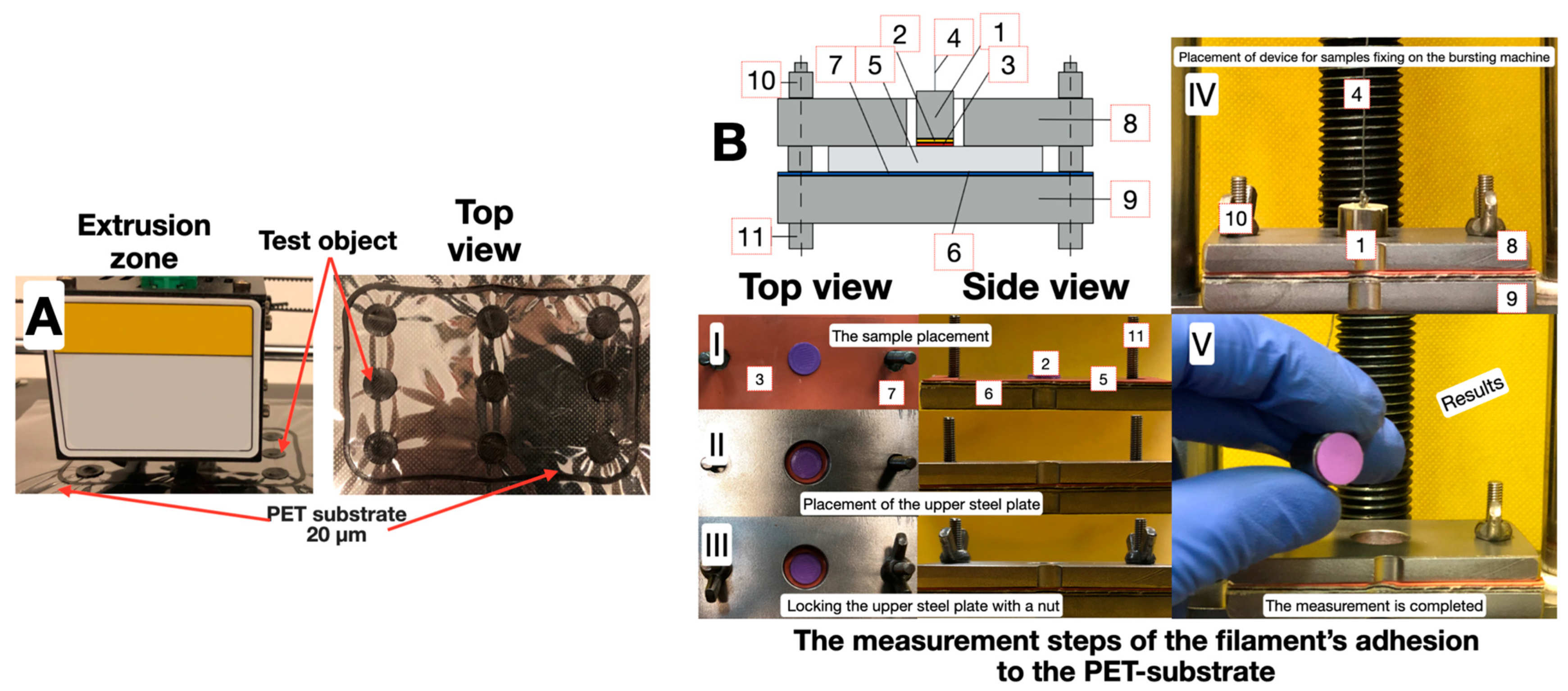
Test objects, as seen in Figure 2, in the form of disks (1 cm2 in area) were made with the PLA filament on the PET-substrate surface to determine the separation strength σ (adhesion) for the filament-substrate contact [72].
Next, a metal cylinder with an area of 1 cm2 was fixed on the test object using the cyanoacrylate glue “Moment” (“Henkel”) and was attached to the upper clamp of the Instron 3382 bursting machine by means of a flexible rod. The strength values were registered in the StretchTest program.

3. Results and Discussion

In order to select the parameters and optimize the mode of the electro-induced multi-gas modification, an auxiliary experiment was carried out. The LDPE substrates were modified at 20, 40, 60, 80, and 100 mA discharge currents. The duration of the modification process was ~15 s due to the low heat resistance of the LDPE. To control the uniformity of the electro-induced multi-gas modification, the wetting contact angles were measured at 10 different locations. The wetting contact angle determination was carried out on the original laboratory stand designed for the high-speed photo/video macrophotography of the wetting process. Close values of the wetting contact angle 45 ± 5 degrees (and, as a result, free surface energies [21]—65 ± 5 mN/m) indicate the homogeneity of the modified surface (U = 1 − δV = 1 − σE/Ē ≈ 0.92). The obtained results were used to calculate the polar and the total samples’ free surface energies for all the samples based on the average values of the measured angles of wetting (Figure 3).
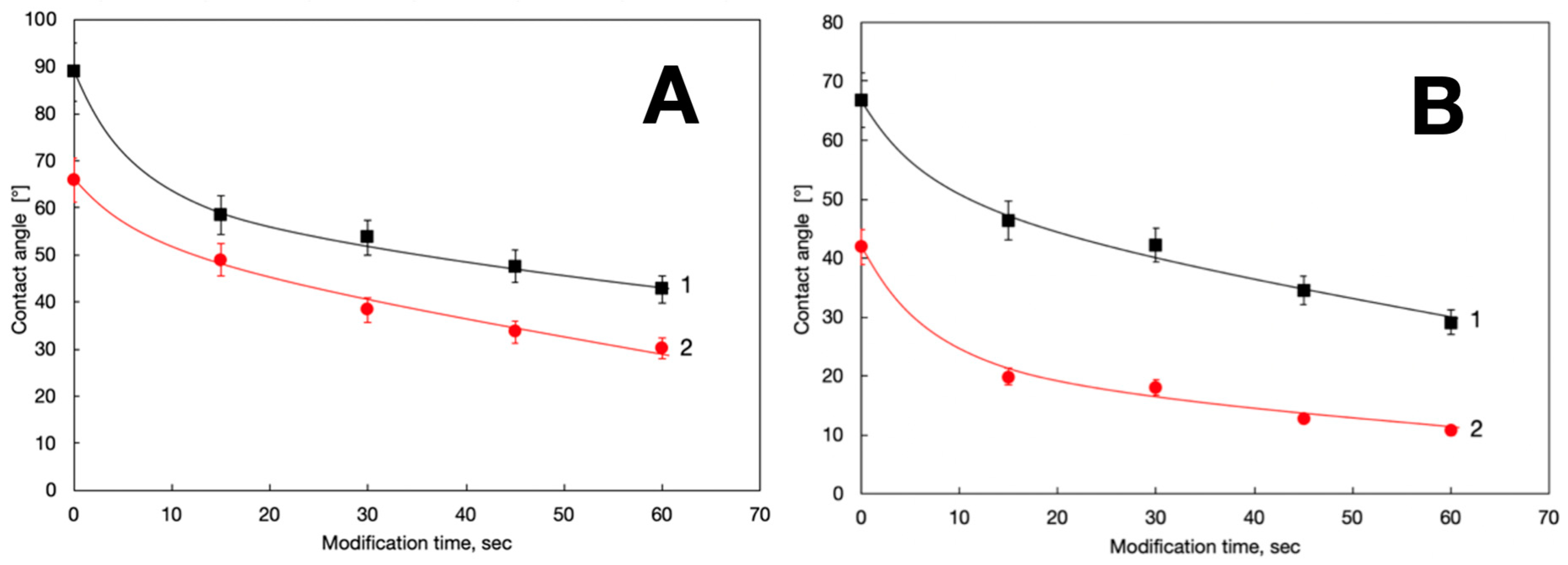
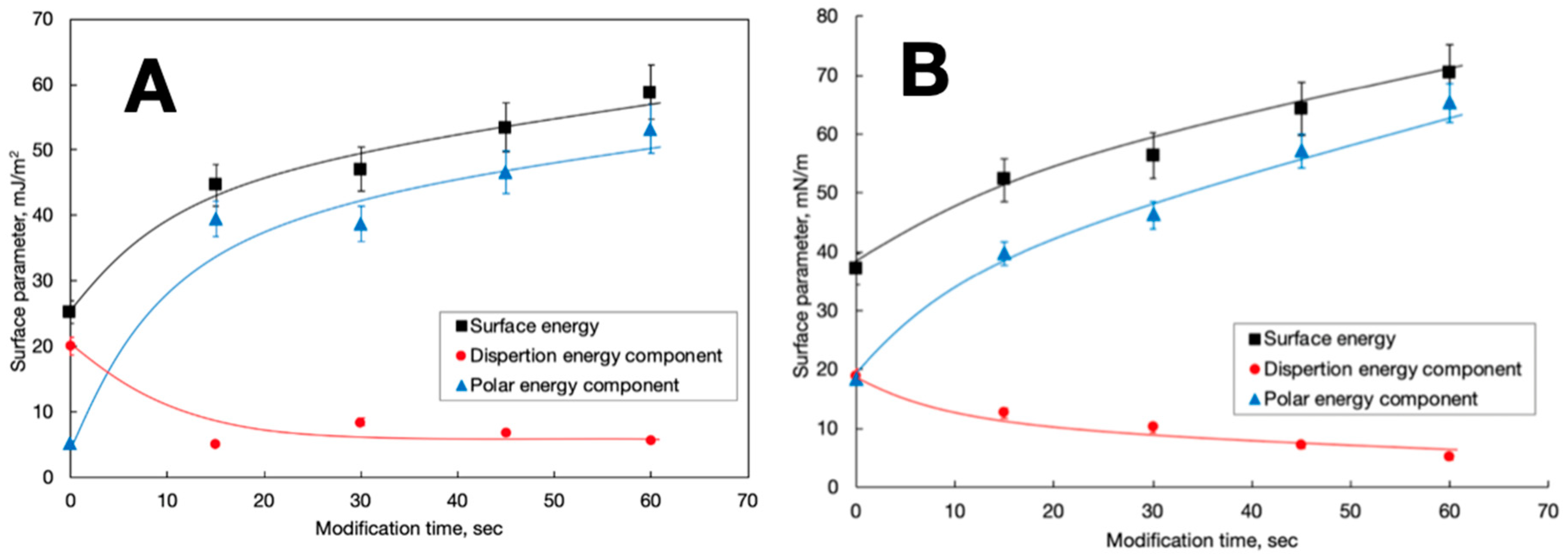
As follows from the histogram, an increase in the polar component with a rise in the discharge current led to a decrease in the contact angle and brought the main contribution to the change in the total free surface energy for all LDPE samples. Since, at a discharge current of 60 mA, almost the maximum value of the free surface energy was reached. This current value was subsequently used in electro-induced multi-gas modification to minimize the thermal action. Similarly, the optimal modification time was also chosen. Figure 4 and Figure 5 show the dependences of the parameter values characterizing the change in the surface properties of the LDPE and PET substrate (lines—calculated values, dots—experimental ones) on the duration of the electro-induced multi-gas modification process.
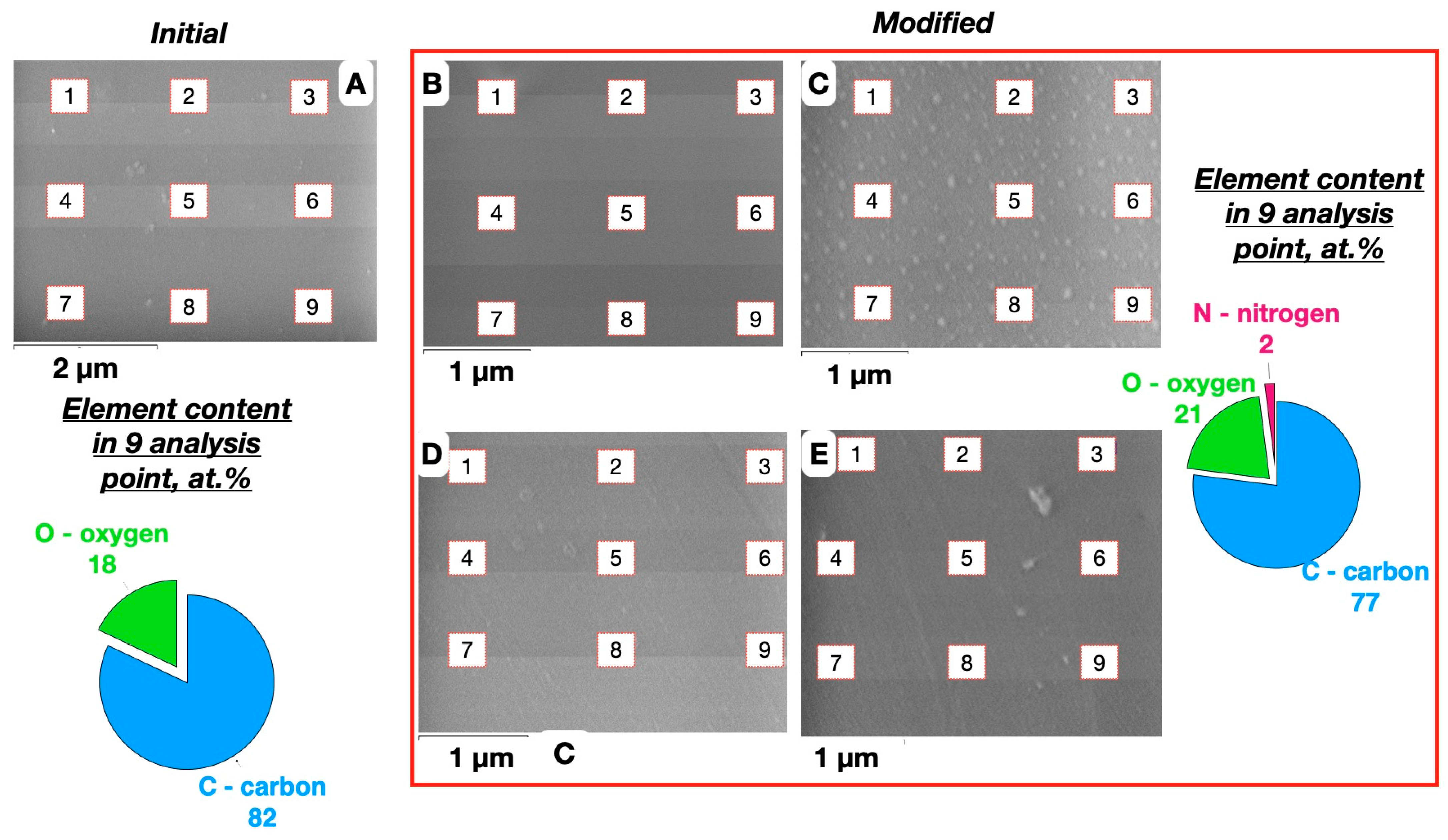
Since the change in wetting contact angles and in the free surface energy slowed down around 60 s of modification, a further increase in the duration seems to be unnecessary due to the need to minimize the thermal action. Note that for the concerned substrates, the change in the total surface energy was achieved mainly due to its polar component, which is associated with the oxidative activity of the gas mixture and the appearance of polar oxygen-containing (carbonyl, carboxyl) groups in the samples’ surface layers. This is confirmed by the results of the SEM and EDS analysis (Figure 6 and Figure 7) of the modified LDPE-substrates.
The EDS analysis (Figure 6) demonstrates that the process of an electro-induced multi-gas modification of an LDPE-substrate contributes to a uniform 2–3 times increase in the oxygen and, accordingly, the oxygen-containing functional groups’ concentration. The source of nitrogen (~2 mass.%) on the modified LDPE-substrate surface is probably the electro-induced chemical reactions of the polymer matrix and atmospheric nitrogen. Similar results are also observed for PET substrates at different durations of plasma-chemical treatment (Figure 7).
The relations between the magnitude of the surface energy and the adhesion of the filament to the polymer substrate surface were then established experimentally (Figure 8).
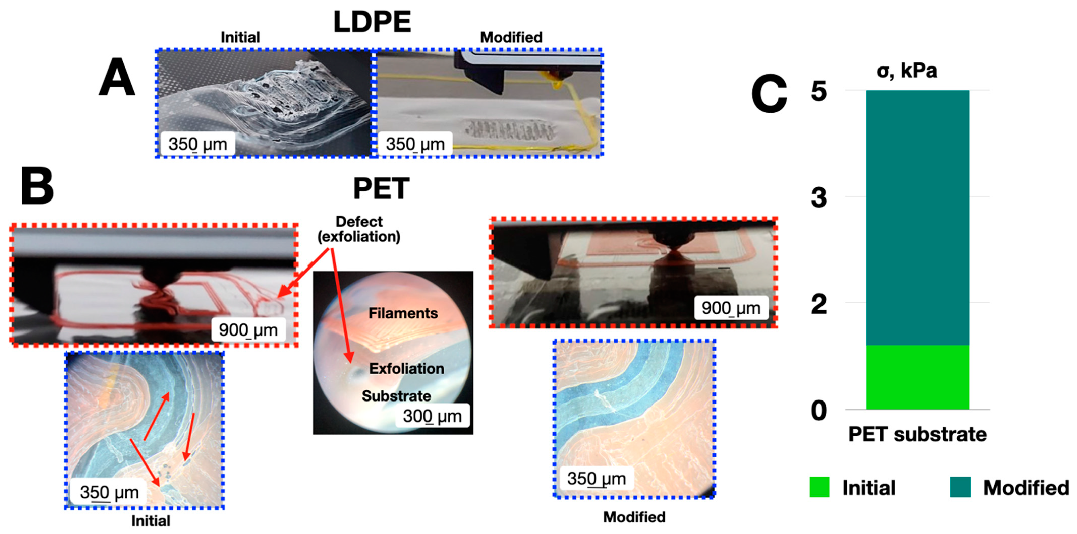
There was no reliable fixation of the PLA filament on the original LDPE substrates. The modified LDPE was not suitable for microdevice element manufacture due to the thermal degradation of the polymer surface during filament deposition (Figure 8A). Printing defects were observed on the surface of the original PET films (caused by unreliable fixation of the PLA filament to the surface due to low adhesion to the initial polymer). This was evidenced by the quantitative values of the strength when tearing the test objects from the polymer surface (Figure 8B). A twofold increase in the surface energy (Figure 5) due to plasma-chemical treatment provided a five-fold increase (5 kPa) in the adhesion of the filament to the modified PET surface and thermal degradation did not appear. Thus, it was possible to form microfluidic features on the nanostructured PET surface.
To assess the change in the surface morphology of the modified substrates, it was necessary to determine the SEM magnification, which would then allow us to demonstrate the corresponding changes. We analyzed the magnifications of 2500×, 10,000×, 15,000×, and 20,000× to find the optimal SEM-measurement mode. The variation-rotational pictures approach was used, i.e., cutting out a 401 × 401 pixel square, we rotated it nine times in a horizontal plane with a 10 degree step and averaged the pixel brightness for each pixel point location (Figure 9).
For the central 256 × 256 square pixel zone we found the mean value, standard deviation, and variation coefficient of the averaged pixel brightness. The dependences of the obtained values on the SEM image magnification are shown in Figure 10.
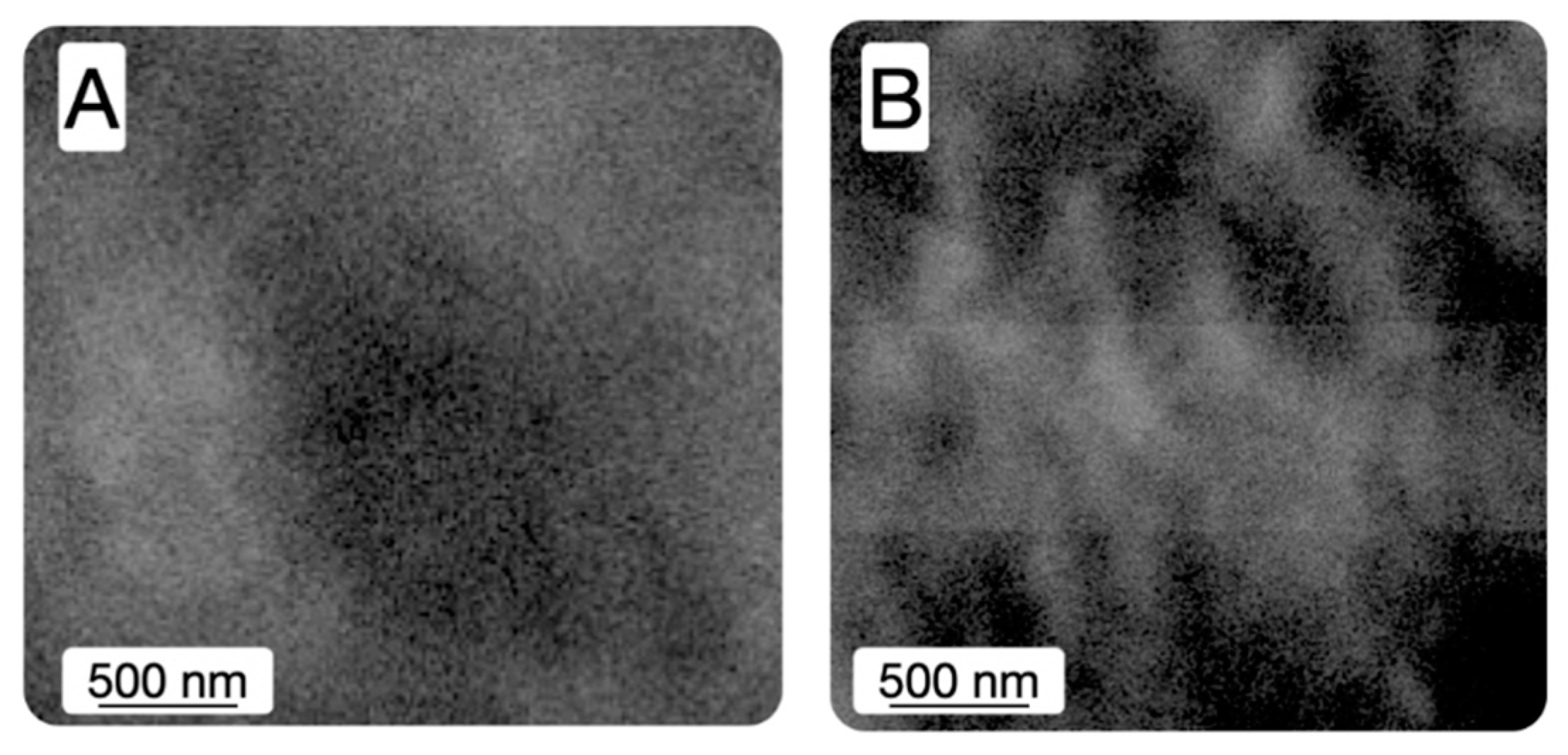
The average value of the pixels’ brightness of the variation-rotation pictures for different magnifications remained almost unchanged (red ellipse). This testifies to the high quality of the adjustment of the measuring equipment and the technique of measurement performance by the SEM operator. Differences between the nanotextures of the initial and modified samples at 20k magnification were observed but may be questioned due to the high error values (yellow circle). In addition, the observed maximum of the mean variation coefficient value V (green circle) was seen at an optimum magnification level of 10,000 (10 k). The SEM images at 10k magnification for the original and 60-second electro-induced multi-gas treated LDPE substrates are shown in Figure 11.
In our previous paper [73], we formulated and tested the concept of constructing a model of the polymer material surface structure based on the corresponding SEM-image expansion into a two-dimensional Fourier series:
I x , y a 0 2   +   k = 1 N / 8 a k · c o s 2 π k x | L · c o s 2 π k y | L   +   b k · c o s 2 π k x | L · s i n 2 π k y | L   +   c k · s i n 2 π k x | L · c o s 2 π k y | L   +   d k · s i n 2 π k x | L · s i n 2 π k y | L
We called «the morphological spectrum» the two-dimensional array:
A k l = a k l 2   +   b k l 2   +   c k l 2   +   d k l 2 · 1   +   φ k l   +   1 φ k l 2 ,
where:
φ k l = a k l · d k l b k l · c k l a k l 2   +   b k l 2   +   c k l 2   +   d k l 2
when a 0 / 2 is the average pixel brightness of the SEM-image and the (k, l)-pair are the biharmonic indices.
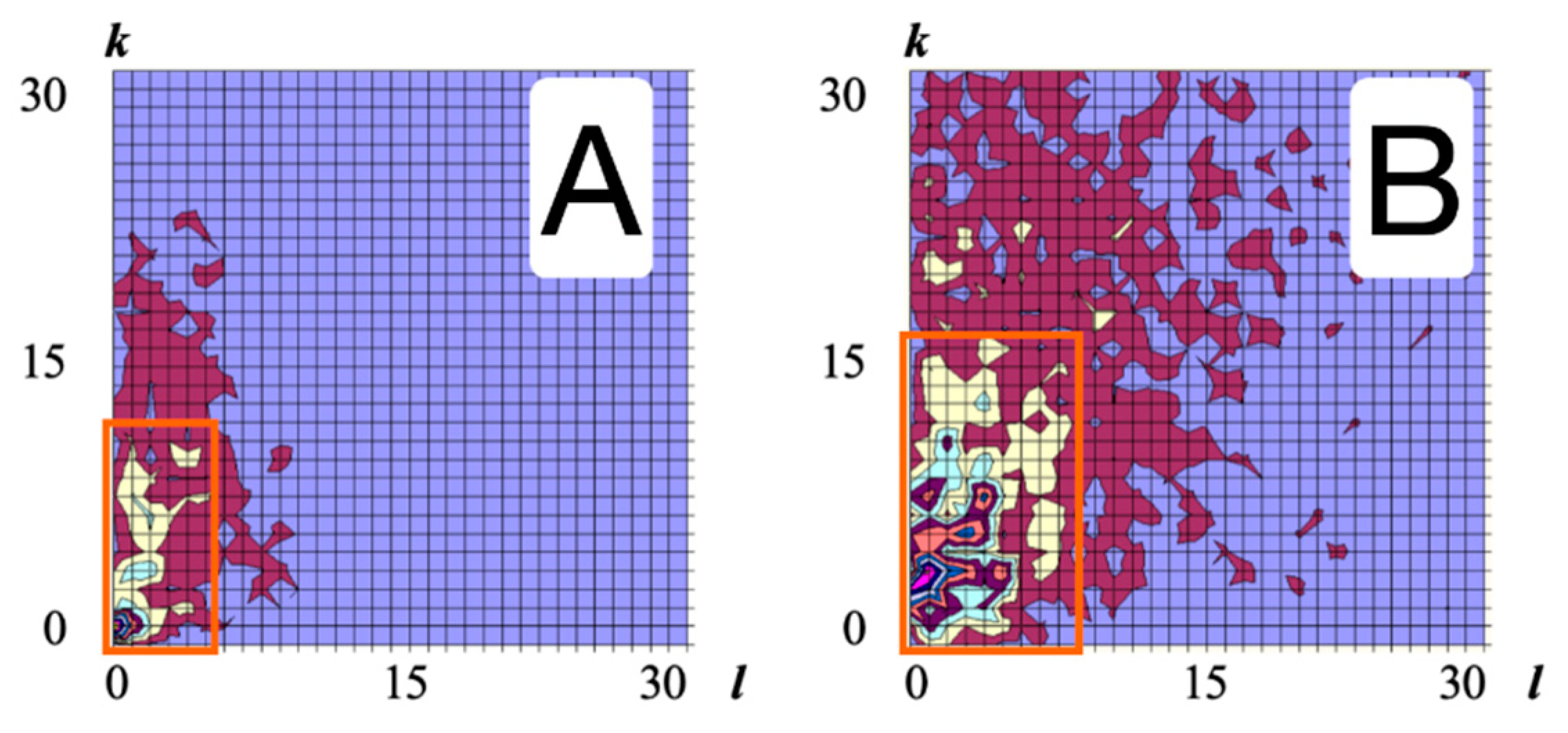
A convenient indicative matrix characteristic of surface heterogeneity is the morphological spectrum [73,74]. Calculating ones for the corresponding SEM images (Figure 11) made it possible to estimate the degrees of the experimental samples’ textural inhomogeneities. The region of the predominant localization of the spectrum of the modified surface increased by more than two times compared to the original one (Figure 12). This fact clearly and quantitatively shows a significant growth in the samples’ textural heterogeneity of the modified surface.
The alteration of the surface nanotexture under the electro-induced multi-gas modification was explained by the electro-induced partial transformation of the amorphous-crystalline structure of the polymer matrix. Electro- and chemo-thermal influences led to numerous acts of local melting of the amorphous cells of the surface. During and after the recrystallization, oxygen ion oxidation occurred in the reactor atmosphere and fixed the changes in the transformed nanotexture of the hydrophilized surface practically without a «gravimetrical trace».

4. Conclusions

Electro-induced multi-gas modification is an effective tool for improving the energy characteristics of the LDPE and PET surface. Using the best (providing the highest representativeness) magnification in the SEM-image formation procedure (which we established by the original variation-rotation pictures technique) we showed that the degrees of textural and morphological heterogeneity of the modified polymer films increased at least twice compared to the original value. Although the traditional gravimetric measurements did not reveal significant changes in the chemical composition of the samples, we established (using the EDS-analysis technique) the appearance of nitrogen and a ~2.5-fold increase in the oxygen content in the modified surface layers of the LDPE and PET films. In addition, we optimized, in terms of the current magnitude and process duration, the modification mode using the results of direct wetting contact angle measurements and the corresponding free surface energy value calculations.
The plasma-chemical modification of PET contributes to a significant increase (~5 times) in filament-to-PET-substrate surface adhesion (due to chemical-morphological transformations). It makes it possible to use extrusion additive prototyping for the formation of microfluidic elements and microdevices on structured polymer substrates for practical applications in microfluidics and printed sensors and for creating nature-like polymeric surface structures.

Author Contributions

F.D. Conceptualization, Writing—original draft, Writing—review and editing; G.R. Methodology, Writing—review and editing; A.E. Validation, Resources; Y.R. Software, Methodology; I.T. Visualization, Resource; V.N. Project administration, Writing—original draft. Funding acquisition. All authors have read and agreed to the published version of the manuscript.

Funding

This work was carried out with the financial support of the Ministry of science and higher education of the Russian Federation (State assignment FZRR-2023-0003).

Data Availability Statement

Not applicable.

Conflicts of Interest

The authors declare no conflict of interest.

References

  1. Bressers, H.J.L.; van Driel, W.D.; Jansen, K.M.B.; Ernst, L.J.; Zhang, G.Q. Correlation between chemistry of polymer building blocks and microelectronics reliability. Microelectron. Reliab. 2007, 47, 290–294. [Google Scholar] [CrossRef]
  2. Krebs, F.C. Pad printing as a film forming technique for polymer solar cells. Sol. Energy Mater. Sol. Cells 2009, 93, 484–490. [Google Scholar] [CrossRef]
  3. Matyushin, V.; Schalkhammer, T.; Rauter, H.; Alguel, Y.; Pittner, F. Nanotechnology for smart polymer optical devices. Macromol. Symp. 2004, 217, 109–133. [Google Scholar]
  4. Zhang, T.; Amin, I.; Sheng, W.; Jordan, R.; Rodriguez, R.D.; Gasiorowski, J.; Rahaman, M.; Kalbacova, J.; Sheremet, E.; Zahn, D.R.T. Bottom-up fabrication of graphene-based conductive polymer carpets for optoelectronics. J. Mater. Chem. C 2018, 6, 4919–4927. [Google Scholar] [CrossRef]
  5. Herrero, J.; Guillén, C. Transparent films on polymers for photovoltaic applications. Vacuum 2002, 67, 611–616. [Google Scholar] [CrossRef]
  6. Zhang, J.; Zhou, T.; Wen, L.; Zhang, A. Fabricating metallic circuit patterns on polymer substrates through laser and selective metallization. ACS Appl. Mater. Interfaces 2016, 8, 33999–34007. [Google Scholar] [CrossRef] [PubMed]
  7. Jiang, X.; Zhao, X.; Li, J.; Lin, S.; Zhu, H. Recent developments in graphene conductive ink: Preparation, printing technology and application. Chin. Sci. Bull. 2017, 62, 3217–3235. [Google Scholar] [CrossRef]
  8. Kravtsova, V.D.; Umerzakova, M.B.; Korobova, N.E.; Vertyanov, D.V. Copper-containing compositions based on alicyclic polyimide for microelectronic applications. Russ. Microelectron. 2018, 47, 455–459. [Google Scholar] [CrossRef]
  9. Molji, C.; Renjith, S.; Sudha, J.D.; Jinesh, K.B. Macroscopically oriented (3-pentadecyl phenol) dangled fluorene based conductive polymer through side chain engineering for microelectronics. Express Polym. Lett. 2019, 13, 1027–1040. [Google Scholar] [CrossRef]
  10. Mukhin, N.; Sokolova, I.; Chigirev, D.; Schmidt, M.-P.; Rudaja, L.; Lebedeva, G.; Bol’shakov, M.; Kastro, R.; Hirsch, S. Composite ferroelectric coatings based on a heat-resistant polybenzoxazole polymer matrix. Coatings 2020, 10, 286. [Google Scholar] [CrossRef] [Green Version]
  11. Ivanov, A.A. Polymer composite materials for semiconductor optoelectronics and microelectronics. Biosci. Biotechnol. Res. Asia 2015, 12, 239–245. [Google Scholar] [CrossRef]
  12. Agrawal, A.; Satapathy, A. Thermal and dielectric behaviour of polypropylene composites reinforced with ceramic fillers. J. Mater. Sci. Mater. Electron. 2014, 26, 103–112. [Google Scholar] [CrossRef]
  13. Lee, J.-W.; Kil Mun, K.; Yoo, Y.T. A comparative study on roll-to-roll gravure printing on PET and BOPP webs with aqueous ink. Prog. Org. Coatings 2009, 64, 98–108. [Google Scholar] [CrossRef]
  14. Siau, S.; Vervaet, A.; Van Calster, A.; Van Vaeck, L.; Schacht, E.; Demeter, U. Adhesion strength of the epoxy polymer/copper interface for use in microelectronics. J. Electrochem. Soc. 2005, 152, C442–C455. [Google Scholar] [CrossRef]
  15. Czvikovszky, T. Expected and unexpected achievements and trends in radiation processing of polymers. Radiat. Phys. Chem. 2003, 67, 437–440. [Google Scholar] [CrossRef]
  16. Nazarov, V.G.; Кoндратoв, A.P.; Stolyarov, V.P.; Evlampieva, L.A.; Baranov, V.A.; Gagarin, M.V. Morphology of the surface layer of polymers modified by gaseous fluorine. Polym. Sci. Ser. A 2006, 48, 1164–1170. [Google Scholar] [CrossRef]
  17. Kumar, A.; Jang, S.Y.; Padilla, J.; Otero, T.F.; Sotzing, G.A. Photopatterned electrochromic conjugated polymer films via precursor approach. Polymer 2008, 49, 3686–3692. [Google Scholar] [CrossRef]
  18. Nazarov, V.G. Multiple surface structures in polyolefins formed by modification methods. J. Appl. Polym. Sci. 2005, 95, 1198–1208. [Google Scholar] [CrossRef]
  19. Nazarov, V.G. Structure and composition of the surface layer in polymers modified by elemental fluorine. J. Appl. Polym. Sci. 2005, 95, 897–902. [Google Scholar] [CrossRef]
  20. Nazarov, V.; Stolyarov, V.; Gagarin, M. Simulation of chemical modification of polymer surface. J. Fluor. Chem. 2014, 161, 120–127. [Google Scholar] [CrossRef]
  21. Nazarov, V.G.; Doronin, F.A.; Evdokimov, A.G.; Rytikov, G.O.; Stolyarov, V.P. Oxyfluorination-Controlled Variations in the Wettability of Polymer Film Surfaces. Colloid J. 2019, 81, 146–157. [Google Scholar] [CrossRef]
  22. Nazarov, V.G.; Stolyarov, V.P.; Doronin, F.A.; Evdokimov, A.G.; Rytikov, G.O.; Brevnov, P.N.; Zabolotnov, A.S.; Novokshonova, L.A.; Berlin, A.A. Comparison of the Effects of Some Modification Methods on the Characteristics of Ultrahigh-Molecular-Weight Polyethylene and Composites on Its Basis. Polym. Sci. Ser. A 2019, 61, 325–333. [Google Scholar] [CrossRef]
  23. Wang, W.; Meng, Q.; Li, Q.; Liu, J.; Jin, Z.; Zhou, M.; Zhao, K. Chitosan derivatives and their application in biomedicine. Int. J. Mol. Sci. 2020, 21, 487. [Google Scholar] [CrossRef] [Green Version]
  24. Chauhan, S.; Jain, N.; Nagaich, U. Nanodiamonds with powerful ability for drug delivery and biomedical applications: Recent updates on in vivo study and patents. J. Pharm. Anal. 2020, 10, 1–12. [Google Scholar] [CrossRef] [PubMed]
  25. Elskens, J.P.; Elskens, J.M.; Madder, A. Chemical modification of aptamers for increased binding affinity in diagnostic applications: Current status and future prospects. Int. J. Mol. Sci. 2020, 21, 4522. [Google Scholar] [CrossRef] [PubMed]
  26. Shum, K.T.; Tanner, J.A. Differential inhibitory activities and stabilisation of DNA aptamers against the SARS coronavirus helicase. Chembiochem 2008, 9, 3037–3045. [Google Scholar] [CrossRef]
  27. Holt, K.B. Diamond at the nanoscale: Applications of diamond nanoparticles from cellular biomarkers to quantum computing. Philos. Trans. R. Soc. A Math. Phys. Eng. Sci. 2007, 365, 2845–2861. [Google Scholar] [CrossRef]
  28. Raty, E.J.-Y.; Galli, G. Ultradispersity of diamond at the nanoscale. Nat. Mater. 2003, 2, 792–795. [Google Scholar] [CrossRef]
  29. Mostovoy, A.S.; Vikulova, M.A.; Lopukhova, M.I. Reinforcing effects of aminosilane-functionalized h-bn on the physicochemical and mechanical behaviors of epoxy nanocomposites. Sci. Rep. 2020, 10, 10676. [Google Scholar] [CrossRef]
  30. Lee, H.; Lim, S.; Birajdar, M.; Lee, S.-H.; Park, H. Fabrication of FGF-2 immobilized electrospun gelatin nanofibers for tissue engineering. Int. J. Biol. Macromol. 2016, 93, 1559–1566. [Google Scholar] [CrossRef] [PubMed]
  31. Chahal, S.; Hussain, F.S.J.; Kumar, A.; Yusoff, M.M.; Rasad, M.S.B.A. Electrospun hydroxyethyl cellulose nanofibers functionalized with calcium phosphate coating for bone tissue engineering. RSC Adv. 2015, 5, 29497–29504. [Google Scholar] [CrossRef] [Green Version]
  32. Rezvani, Z.; Venugopal, J.R.; Urbanska, A.M.; Mills, D.K.; Ramakrishna, S.; Mozafari, M. A bird’s eye view on the use of electrospun nanofibrous scaffolds for bone tissue engineering: Current state-of-the-art, emerging directions and future trends. Nanomed. Nanotechnol. Biol. Med. 2016, 12, 2181–2200. [Google Scholar] [CrossRef] [PubMed]
  33. Sakdaronnarong, C.; Sangjan, A.; Boonsith, S.; Kim, D.C.; Shin, H.S. Recent developments in synthesis and photocatalytic applications of carbon dots. Catalysts 2020, 10, 320. [Google Scholar] [CrossRef] [Green Version]
  34. Castro-Muñoz, R.; Ahmad, M.Z.; Fíla, V. Tuning of nano-based materials for embedding into low-permeability polyimides for a featured gas separation. Front. Chem. 2020, 7, 897. [Google Scholar] [CrossRef] [PubMed] [Green Version]
  35. Lonergan, M.C.; Cheng, C.H.; Langsdorf, B.L.; Zhou, X. Electrochemical characterization of polyacetylene ionomers and polyelectrolyte-mediated electrochemistry toward interfaces between dissimilarly doped conjugated polymers. J. Am. Chem. Soc. 2002, 124, 690–701. [Google Scholar] [CrossRef] [PubMed]
  36. Maex, K.; Shamiryan, D.; Iacopi, F.; Brongersma, S.H.; Baklanov, M.R.; Yanovitskaya, Z.S. Low dielectric constant materials for microelectronics. J. Appl. Phys. 2003, 93, 8793–8841. [Google Scholar] [CrossRef]
  37. Menegatti, E.; Berardi, D.; Messina, M.; Giachino, O.; Restagno, G.; Roccatello, D.; Ferrante, I.; Spagnolo, B.; Cognolato, L. Lab-on-a-chip: Emerging analytical platforms for immune-mediated diseases. Autoimmun. Rev. 2013, 12, 814–820. [Google Scholar] [CrossRef]
  38. Junkar, I. Plasma treatment of amorphous and semicrystalline polymers for improved biocompatibility. Vacuum 2013, 98, 111–115. [Google Scholar] [CrossRef]
  39. Popelka, A.; Kronek, J.; Novák, I.; Kleinová, A.; Mičušík, M.; Špírková, M.; Omastová, M. Surface modification of low-density polyethylene with poly(2-ethyl-2-oxazoline) using a low-pressure plasma treatment. Vacuum 2014, 100, 53–56. [Google Scholar] [CrossRef]
  40. Louzi, V.C.; Campos, J.S.D.C. Corona treatment applied to synthetic polymeric monofilaments (PP, PET, and PA-6). Surf. Interfaces 2019, 14, 98–107. [Google Scholar] [CrossRef]
  41. Dai, L.; Xu, D. Polyethylene surface enhancement by corona and chemical co-treatment. Tetrahedron Lett. 2019, 60, 1005–1010. [Google Scholar] [CrossRef]
  42. Udomluck, N.; Park, H.; Koh, W.-G.; Lim, D.-J. Recent developments in nanofiber fabrication and modification for bone tissue engineering. Int. J. Mol. Sci. 2020, 21, 99. [Google Scholar] [CrossRef] [Green Version]
  43. Siow, K.S.; Britcher, L.; Kumar, S.; Griesser, H.J. Plasma methods for the generation of chemically reactive surfaces for biomolecule immobilization and cell colonization—A review. Plasma Process. Polym. 2006, 3, 392–418. [Google Scholar] [CrossRef]
  44. Chen, J.-P.; Su, C.-H. Surface modification of electrospun PLLA nanofibers by plasma treatment and cationized gelatin immobilization for cartilage tissue engineering. Acta Biomater. 2011, 7, 234–243. [Google Scholar] [CrossRef]
  45. Ho, M.-H.; Hou, L.-T.; Tu, C.-Y.; Hsieh, H.-J.; Lai, J.-Y.; Chen, W.-J.; Wang, D.-M. Promotion of cell affinity of porous PLLA scaffolds by immobilization of RGD peptides via plasma treatment. Macromol. Biosci. 2006, 6, 90–98. [Google Scholar] [CrossRef] [PubMed]
  46. Sanders, J.E.; Lamont, S.E.; Karchin, A.; Golledge, S.L.; Ratner, B.D. Fibro-porous meshes made from polyurethane micro-fibers: Effects of surface charge on tissue response. Biomaterials 2005, 26, 813–818. [Google Scholar] [CrossRef]
  47. Manakhov, A.; Kedronová, E.; Medalová, J.; Cernochová, P.; Obrusník, A.; Michlícek, M.; Shtansky, D.V.; Zajíčková, L. Carboxyl-anhydride and amine plasma coating of PCL nanofibers to improve their bioactivity. Mater. Des. 2017, 132, 257–265. [Google Scholar] [CrossRef]
  48. Vesel, A.; Primc, G.; Zaplotnik, R.; Mozetič, M. Applications of highly non-equilibrium low-pressure oxygen plasma for treatment of polymers and polymer composites on an industrial scale. Plasma Phys. Control Fusion 2020, 62, 024008. [Google Scholar] [CrossRef]
  49. Karakassides, A.; Ganguly, A.; Papakonstantinou, P.; Tsirka, K.; Paipetis, A.S. Radi-ally grown graphene nanoflakes on carbon fibers as reinforcing interface for polymer composites. ACS Appl. Nano Mater. 2020, 3, 2402–2413. [Google Scholar] [CrossRef] [Green Version]
  50. Lapenna, A.; Fracassi, F.; Armenise, V.; Angarano, V.; Palazzo, G.; Fanelli, F.; Mal-lardi, A. Direct exposure of dry enzymes to atmospheric pressure non-equilibrium plas-mas: The case of tyrosinase. Materials 2020, 13, 2181. [Google Scholar] [CrossRef]
  51. Pagliusi, P.; Audia, B.; Provenzano, C.; Cipparrone, G.; Piñol, M.; Oriol, L. Tunable surface patterning of azopolymer by vectorial holography: The role of photoanisotropies in the driving force. ACS Appl. Mater. Interfaces 2019, 11, 34471–34477. [Google Scholar] [CrossRef] [PubMed]
  52. Sochol, R.D.; Sweet, E.; Glick, C.C.; Wu, S.Y.; Yang, C.; Restaino, M.; Lin, L. 3D printed microfluidics and microelectronics. Microelectron. Eng. 2018, 189, 52–68. [Google Scholar] [CrossRef]
  53. Choong, Y.Y.C.; Tan, H.W.; Patel, D.C.; Choong, W.T.N.; Chen, C.H.; Low, H.Y.; Tan, M.J.; Patel, C.D.; Chua, C.K. The global rise of 3D printing during the COVID-19 pandemic. Nat. Rev. Mater. 2020, 5, 637–639. [Google Scholar] [CrossRef] [PubMed]
  54. Ward, K.; Fan, Z.H. Mixing in microfluidic devices and enhancement methods. J. Micromech. Microeng. 2015, 25, 094001. [Google Scholar] [CrossRef] [Green Version]
  55. Waheed, S.; Cabot, J.M.; Macdonald, N.P.; Paull, B.; Breadmore, M.C.; Lewis, T.; Guijt, R.M. 3D printed microfluidic devices: Enablers and barriers. Lab A Chip Miniat. Chem. Biol. 2016, 16, 1993–2013. [Google Scholar] [CrossRef] [Green Version]
  56. Razavi Bazaz, S.; Rouhi, O.; Raoufi, M.A.; Ejeian, F.; Ebrahimi Warkiani, M.; Asadnia, M.; Jin, D. 3D printing of inertial microfluidic devices. Sci. Rep. 2020, 10, 5929. [Google Scholar] [CrossRef] [Green Version]
  57. Saghir, N.; Aggarwal, A.; Soneji, N.; Valencia, V.; Rodgers, G.; Kurian, T. A comparison of manual electrocardiographic interval and waveform analysis in lead 1 of 12-lead ECG and Apple Watch ECG: A validation study. Cardiovasc. Digit. Health J. 2020, 1, 30–36. [Google Scholar] [CrossRef]
  58. Zhao, Y.; Wang, B.; Hojaiji, H.; Wang, Z.; Lin, S.; Yeung, C.; Lin, H.; Nguyen, P.; Chiu, K.; Salahi, K.; et al. A wearable freestanding electrochemical sensing system. Sci. Adv. 2020, 6, eaaz0007. [Google Scholar] [CrossRef] [Green Version]
  59. Tison, G.H.; Sanchez, J.M.; Ballinger, B.; Singh, A.; Olgin, J.E.; Pletcher, M.J.; Vittinghoff, E.; Lee, E.S.; Fan, S.M.; Gladstone, R.A.; et al. Passive detection of atrial fibrillation using a commercially available smart watch. JAMA Cardiol. 2018, 3, 409–416. [Google Scholar] [CrossRef] [Green Version]
  60. Sequeira, N.; D’Souza, D.; Angaran, P.; Aves, T.; Dorian, P. Common wearable devices demonstrate variable accuracy in measuring heart rate during supraventricular tachycardia. Heart Rhythm. 2020, 17, 854–859. [Google Scholar] [CrossRef]
  61. Kang, Z.; Zhang, Y.; Zhou, M. AgNPs@CNTs/Ag hybrid films on thiolated PET substrate for flexible electronics. Chem. Eng. J. 2019, 368, 223–234. [Google Scholar] [CrossRef]
  62. Kondratov, A.P.; Nagornova, I.V.; Varepo, L.G. Tenso-resistive printed sensors forf lexible elements of systems and mechanisms. J. Phys. Conf. Ser. 2019, 1210, 012067. [Google Scholar] [CrossRef]
  63. Deganello, D.; Cherry, J.A.; Gethin, D.T.; Claypole, T.C. Impact of metered ink volume on reel-to-reel flexographic printed conductive networks for enhanced thin film conductivity. Thin Solid Film. 2012, 520, 2233–2237. [Google Scholar] [CrossRef]
  64. Deganello, D.; Cherry, J.A.; Gethin, D.T.; Claypole, T.C. Patterning of micro-scale conductive networks using reel-to-reel flexographic printing. Thin Solid Film. 2010, 518, 6113–6116. [Google Scholar] [CrossRef]
  65. Núñez, C.G.; Navaraj, W.T.; Polat, E.O.; Dahiya, R. Energy-autonomous, flexible, and transparent tactile skin. Adv. Funct. Mater. 2017, 27, 1606287. [Google Scholar] [CrossRef] [Green Version]
  66. Walker, B.W.; Annabi, N.; Portillo Lara, R.; Hsiang Yu, C.; Kimball, W.; Mogadam, E. Rational design of microfabricated electroconductive hydrogels for biomedical applications. Prog. Polym. Sci. 2019, 92, 135–157. [Google Scholar] [CrossRef] [Green Version]
  67. Khan, S.; Ali, S.; Bermak, A. Recent developments in printing flexible and wearable sensing electronics for healthcare applications. Sensors 2019, 19, 1230. [Google Scholar] [CrossRef] [Green Version]
  68. Available online: https://pinshape.com/items/40493-3d-printed-lesson-of-design-of-microfluidics-channels (accessed on 18 December 2022).
  69. El Moumen, A.; Tarfaoui, M.; Lafdi, K. Modelling of the temperature and residual stress fields during 3D printing of polymer composites. Int. J. Adv. Manuf. Technol. 2019, 104, 1661–1676. [Google Scholar] [CrossRef]
  70. Hilberman, M.; Hogan, J.S.; Peters, R.M. The effects of carbon dioxide on pulmonary mechanics in hyperventilating, normal volunteers. J. Thorac. Cardiovasc. Surg. 1976, 71, 268–273. [Google Scholar] [CrossRef]
  71. Kerolli-Mustafa, M.; Çadraku, H.; Musliu, A. Surface characterization of glas fibers made from jarosite waste using contact angle measurements. IFAC-PapersOnLine 2016, 49, 196–199. [Google Scholar] [CrossRef]
  72. Doronin, F.; Rudyak, Y.; Rytikov, G.; Evdokimov, A.; Nazarov, V. 3D-printed planar microfluidic device on oxyfluorinated PET-substrate. Polym. Test. 2021, 99, 107209. [Google Scholar] [CrossRef]
  73. Drozdov, S.; Nazarov, V.; Nozdrachev, S.; Rudyak, Y.; Rytikov, G. The polymer composites’ morphological structure simulation. Nanosyst. Phys. Chem. Math. 2017, 8, 137–145. [Google Scholar] [CrossRef] [Green Version]
  74. Petrushin, V.N.; Rudyak, Y.V.; Rytikov, G.O. The representativeness of the statistical data frame in the quantitative image analysis. ITM Web Conf. 2018, 18, 01007. [Google Scholar] [CrossRef] [Green Version]
Figure 1. Schematic of a plasma-chemical plant for PET modification (A); configuration of microfluidic elements [68] (B); and schematic diagram of 3D printing by (FFF) (C) [69].
Processes 11 00774 g001
Figure 2. The 3D-printed test objects on the surface of the PET-substrate (A); the diagram of the device for sample fixing on the Instron 3382 bursting machine: 1—the metal cylinder with an adhesive layer; 2—the test object; 3—the PET-substrate; 4—the Kevlar twisted thread; 5—the tested sample; 6—the double-sided adhesive tape; 7—the rubber gasket; 8 –the upper steel plate with a hole for the metal cylinder; 9—the lower steel plate; 10—the nut; 11—the bolt (B) [72].
Processes 11 00774 g002
Figure 3. The histograms of the 15-s modified LDPE-substrates’ wetting contact angle (blue), polar component (green), and total value (orange) of the free surface energy dependence on the discharge current values.
Processes 11 00774 g003
Figure 4. The dependences of the LDPE (A) and PET (B) substrates’ wetting contact angle with distilled water (1) and with ethylene glycol (2) on the duration of electro-induced multi-gas modification.
Processes 11 00774 g004
Figure 5. The dependences of the LDPE (A) and PET (B) substrates’ free surface energy and its components on the duration of electro-induced multi-gas modification.
Processes 11 00774 g005
Figure 6. The SEM and EDS analyses (in weight %) of the two micron surface layers of the initial (A) and treated (B) LDPE-substrates. C—carbon; N—nitrogen; O—oxygen.
Processes 11 00774 g006
Figure 7. The SEM and EDS analyses (in weight %) of the two micron surface layers of the initial (A) and treated 15 s (B); 30 s (C); 45 s (D); and 60 s (E) PET-substrates. C—carbon; N—nitrogen; O—oxygen.
Processes 11 00774 g007
Figure 8. Optical quality control of microdevice elements’ reproduction on the initial and modified LDPE—(A) and PET—(B) (printing defects are indicated by red arrows); the PLA filament peel strength—(C).
Processes 11 00774 g008
Figure 9. The variation-rotational pictures for the initial—(A) and the modified—(BE) samples obtained from the SEM images of different magnification: 20 k—(A,B); 15 k—(C); 10 k—(D); and 2.5 k—(E).
Processes 11 00774 g009
Figure 10. The mean (A), standard deviation (B), and variation coefficient (C) values for the variation-rotational pictures obtained from the SEM images under the different magnification levels (2.5 k; 10 k; 15 k, and 20 k). (INI—initial sample at 20k magnification; others—modified, different magnification). The red ellipse and yellow and green circles are explained in the text.
Processes 11 00774 g010
Figure 11. The SEM images at 10 k magnification of the original (A) and the modified (B) LDPE-substrates’ surfaces.
Processes 11 00774 g011
Figure 12. The SEM images’ morphological spectra of the initial—(A) and the modified—(B) samples; k, l—the biharmonic indexes. The orange rectangles show the localization zones of the spectra.
Processes 11 00774 g012
Disclaimer/Publisher’s Note: The statements, opinions and data contained in all publications are solely those of the individual author(s) and contributor(s) and not of MDPI and/or the editor(s). MDPI and/or the editor(s) disclaim responsibility for any injury to people or property resulting from any ideas, methods, instructions or products referred to in the content.