
Study of Scavenging and Combustion Processes for Small Two-Stroke Aviation Heavy Fuel Direct Injection Engines

1
School of Energy and Power Engineering, Beihang University, Beijing 100191, China
2
Research Institute of Aero-Engine, Beihang University, Beijing 100191, China
3
Wuhan Second Ship Design and Research Institute, Wuhan 430205, China
4
Aero Engine Academy of China, Beijing 100191, China
5
Department of Aviation Engineering, Civil Aviation University of China, Tianjin 300300, China
6
Beihang Hangzhou Innovation Institute Yuhang, Hangzhou 310023, China
*
Author to whom correspondence should be addressed.
Processes 2023, 11(2), 583; https://doi.org/10.3390/pr11020583
Submission received: 31 December 2022
/
Revised: 8 February 2023
/
Accepted: 10 February 2023
/
Published: 14 February 2023
(This article belongs to the Section Energy Systems)
Abstract
:Heavy-fuel aviation piston engines (HF-APEs) are widely used in general aviation and unmanned aerial vehicle (UAV) due to their safety and fuel economy. This paper describes a numerical and experimental study of scavenging and combustion processes on a 2-Stroke Direct Injected HF-APEs for light aircraft, with its cylinder specifically designed as cross scavenging. A 3-Dimentional transient model of in-cylinder flow and combustion process is established by the Forte platform, and the engine test system is set up. By comparing the simulation results to the experimental results, it showed that multi-ports cross scavenging can generate unbalanced aerodynamic torque in the cylinder. In the compression process, the swirl ratio (SR) gradually increases, and the peak SR reaches 15. Moreover, approximately 25% of exhaust residual gas in the cylinder is conducive to the fuel atomization and evaporation process in a high-altitude environment. When the injection timing is between −8 °CA and −16 °CA, the engine has the optimal power and economy performance at different altitudes. Finally, when the injection advance angle moves forward by 4 °CA, the maximum pressure increases by 2 MPa, with the rising rate decreasing gradually. The results have important significance for the development of the combustion system of small 2-Stroke Direct Injected HF-APEs.
1. Introduction
As is well known, aviation piston engines (APEs) are developing toward high power density [1]. Compared with four-stroke engines, the high-speed two-stroke engine for light aircraft has higher specific power per weight and displacement volume, as well as better thermal efficiency [2]. In recent years hybrid power systems are gradually developed in general aviation due to their excellent power performance and economic performance [3]. However, the series-parallel hybrid system is not suitable for small UAVs because it requires transmission systems [4,5]. In addition, the current controller cannot fulfill all the tasks faultlessly in the energy management process [6]. Therefore, small internal combustion (IC) engines are still the main powerplants of model airplanes [7]. The design parameters of the combustion chamber and the operating conditions of APEs have a direct impact on combustion and emission characteristics [8]. It can be predicted that HF-APEs will gradually replace the existing aviation gasoline engines and become the main power system of general aviation aircraft, as well as long-endurance UAVs in the future [9]. For an aircraft diesel engine, the priorities for optimization are reliability and performance [10,11]. Due to the small displacement and high-speed reciprocating motion of the cylinder, the fuel-air mixing, combustion space, and time are greatly limited during direct injection in the cylinder, and combustion organization is difficult [12]. Excessive fuel accumulation on the surface of the combustion chamber due to the contradiction between the fuel spray penetration distance and the combustion chamber diameter, increased smoke emissions at high loads [13]. Therefore, the analysis of scavenging and combustion processes of heavy fuel direct injection small APEs is the key to improving the comprehensive performance of the engine [14].
It was found that the DI combustion system yields several advantages: better take-off performance (higher power output), lower fuel consumption at cruise conditions, improved altitude performance, and reduced cooling requirements [15]. Carlos J. used the heat release analysis method to investigate the factor, which influences pilot-injection combustion [16]. Busch S et al. from Sandia National Laboratories, compared the combustion performance of three different types of pistons, which showed that the stepped-lip piston led to higher thermal efficiency [17]. Yang et al. analyzed the interactions between sprays and sprays with swirls using Flame Image Velocimetry (FIV), which showed that swirls could enhance the mixing [18]. Le M K et al. investigated the flame-moving process in a small heavy fuel engine by optical method, which showed that the spray hit the combustion chamber wall soon after the start of injection and a part of them would rebound while others would expand along the combustion chamber wall [19]. Pradeep M. summarized several conclusions and analyzed the trend of development in a small naturally aspirated CRDI diesel engine [20]. Based on the particle sampling method of thermophoresis, Zhang Y L et al. found that half of the combustion flame propagated against the swirl, while the other half developed in the same direction due to the influence of the swirl in the small-bore diesel engine [21]. Francesco B et al. proposed a method in which the fuel is injected into the combustion chamber intermittently, which leads to the fresh air being less diluted by the residual gas and the combustion efficiency increasing [22]. Xue M established the simulation model of in-cylinder combustion of piston aviation and verified by experiments, which state that the combustion center of gravity will increase by increasing the ignition advance angle [23]. Pan Z J et al. analyzed the impact of combustion chamber diameter and depth on emissions, which showed that properly reducing combustion chamber diameter and diameter-depth ratio can reduce emissions [24].
Zhou Y et al. analyzed the trends of cutting-edge technologies and the theory of gas exchange [25,26]. James W. G. compared different scavenging systems for 2-stroke engines, which showed that the opposed-piston has the best scavenging effect and the highest thermal efficiency, because the structure can achieve maximum thermal expansion and minimum heat loss [27]. In order to increase the engine braking power during take-off and reduce the engine fuel consumption under cruise conditions, Carlucci A P et al. analyzed the characteristics of a two-stroke uniflow diesel engine and compared the simulations to the test data [28]. In order to improve combustion efficiency, Hu CM et al. proposed the application of the AADI system in spark-ignition piston aero-engine [29]. Xu Z et al. predicted the high altitude performance of Poppet-valves 2-Stroke (PV2S) aircraft diesel engine, and the results showed that the high altitude power loss of the PV2S engine was more serious than the traditional two-stroke engine [30,31]. Chen Y L et al. used different swirl ratio tests to study the effect of intake swirl on engine combustion performance, the results showed that the best fuel/air mixture and combustion performance were obtained in the direct injection diesel engine without intake swirl [32]. Pavel B et al. proposed a method to analyze the correlation between the residual gas fraction in the exhaust port and the residual gas fraction in the cylinder using the scavenging curve [33]. Despite a large number of experimental investigations that have been implemented to explore the small two-stroke engine performance, there is no systematic treatment of combustion characteristics and altitude characteristics with a small two-stroke engine.
Yusuf A.A. et al. studied the effects of spark timing and alternative fuels on engine performance, combustion, and tailpipe emissions [34]. Shirvani S. et al. have conducted extensive research. He examined the effects of a number of nozzles, injection pressure, fuel line angle, and the start of injection (SOI) in two-stroke engines. Results revealed that advancing the start of injection by two crank angle degrees (CAD) can reduce soot emissions by 16%, and with the strategy of pre-injection, NOx is reduced by 37% [35]. Mitianiec W. studied the combustion behavior with different piston positions and asymmetric scavenging timing. They reported that earlier opening of exhaust ports can decrease CO emission because of a lower combustion temperature [36]. Chang C. and Wei M.X.’s experiments on two-stroke APEs studied the impact of the mixture concentration on the cylinder pressure, cylinder temperature, and engine power, the results show that a rich mixture with early Injection advance angle has a better effect on the knock suppression [37]. Zhenfeng Z. et al. through CFD to analyze aviation kerosene combustion characteristics, and reported that a worse equivalence ratio led to knocking combustion [38].
Therefore, to orderly organize the airflow and accelerate spray and air mixing in the cylinder of the two-stroke heavy fuel direct injection engine [39]. A detailed study into the performance of the small two-stroke HF-APEs is presented in this article, which incorporates experimental and computational fluid dynamics (CFD) analysis to explore the optimization direction of scavenging and combustion systems for small heavy fuel direct injection engines.
2. Experimental
2.1. Engine Description
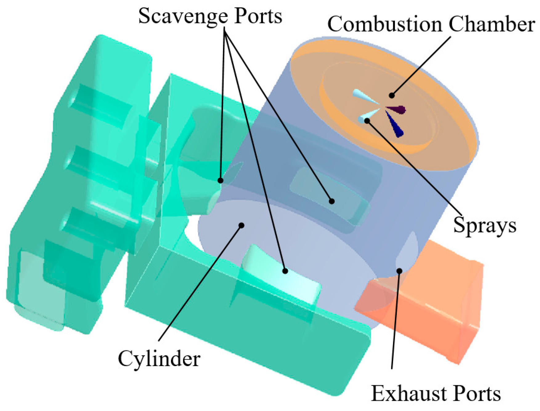
A small 2-stroke APEs adopts a cross-flow scavenging system, which has three intake ports, and one exhaust port. The combustion system is configured with a direct-injection and bowl-shaped combustion chamber. The actual engine is illustrated in Figure 1. The type and geometric parameters of the engine are shown in Table 1.
2.2. Experimental Set Up
The schematic diagram of the experimental system is shown in Figure 2, which includes the flow system, a cylinder pressure sensor, and a dynamometer test system.
The Roots blower simulation intake supercharging system, with a variable-frequency drive to adjust the volumetric flow into the air bottle. Firstly, the working fluid flows into an air bottle, which keeps intake pressure constant by a spill valve at the head. Setting up the air volumetric flow rate is 16 L/s and the error is within ±5%. Then, the air from air bottle to the air box, enters two cylinders through intake ports symmetrically. The engine and measuring modules are assembled as shown in Figure 3. The airflow meter and air pressure meter can measure the mass of air entering the engine at a constant speed [40]. The cylinder pressure sensor collects, analyzes, and stores the cylinder pressure signal in the combustion process of the engine in real-time. The phase sensor can measure the start of injection and the end of the injection. In this paper, the rate of injection profile of nozzles was measured by the momentum flux method [41]. Figure 4 shows a test bench for measuring fuel injection speed. A pressure sensor is installed at a certain distance from the nozzle outlet to measure the impact force of the spray. The change of velocity before and after the impact of liquid drops in the direction perpendicular to the sensor surface is equal to the impact velocity of liquid drops.
Detailed parameters are shown in Table 2.
The shape of the scavenging ports and the exhaust port is rectangular, whose lower boundary is just flush with the piston at the bottom dead center (BDC).
3. CFD Simulation
3.1. Mesh and Initial Boundary Condition Settings
Ansys Forte is used in the simulation [42]. Import a complete 3-D geometric model to simulate the working process of a small two-stroke heavy fuel direct injection engine for grid generation, and use the grid generation tool provided by Forte for pre-processing, while adjusting the grid size near the airport. The tetrahedron grid is used for the calculation of the intake and exhaust port area, and the hexahedron grid is used for the calculation of the intake and exhaust ports and cylinder volume, which is dynamic grid. The three-dimensional transient calculation mode is selected. A single cylinder is taken for calculation because the working conditions of the two cylinders are the same. RNG k-ε Turbulence model and standard wall function are adopted, and the calculation step is 1 °CA crankshaft angle.
The global mesh size is specified as 2 mm, the mesh preview of the combustion chamber is shown in Figure 5. A total of 329,023 meshes are generated.
The simulated inlet and outlet adopt pressure boundary conditions and keep the pressure constant. To simulate the coupling relationship with the supercharger. The inlet is set to the theoretical pressure behind the compressor, and the outlet is set to the theoretical pressure in front of the turbine. The relevant boundary and initial conditions for calculation are shown in Table 3.
The fuel injection system is configured with a 4-hole solid-cone mechanical injector. As a common application in CFD simulations, the most commonly used is the quasi-steady spray cone angle [43]. The spray cone angle is set to 15 degrees, the included angle between fuel jets is set to 150° and the temperature of spray droplets in the nozzle chamber is about 400 K. These settings are consistent with the physical object absolutely. Assuming a constant discharge coefficient is 0.7 based on the momentum measurement method. The injection strategy adopts single pulse injection and the droplet size distribution is set to Uniform Size. The Kelvin-Helmholyz/Rayleigh-Taylor (KH/RT) model is adopted for atomization and droplet breakup, which can improve the temperature dependence of the fuel penetration and predict a better distribution of droplet size [44,45]. In this study, we set the model constants in Appendix A. Adjust the liquid penetration by decreasing the RT constant, the parent parcel breaks up to form new droplets with different KH constants. Using a discrete multi-component (DMC) fuel-vaporization model to represent the vaporization of spray droplets, DMC is formulated to track each component of the fuel regardless of the direction of the process [46,47]. The Adaptive Collision Mesh Model is used in modeling droplet collision and coalescence [48]. The gas entrainment constant in the gas phase jet model is set to 0.5.
3.2. Validation of the Model
In order to verify the accuracy of the simulation model generated in Forte, this work compared the simulation results to the test data, the results are shown in Figure 6. Results show that the maximum error of cylinder pressure calculated by simulation and measured by the test is about 3%, the combustion phase is basically consistent, therefore, considering the simulation model is reliable and accurate.
According to Table 4 working conditions, the characteristics of fuel atomization and evaporation, combustion, and scavenging processes of small two-stroke heavy fuel direct injection engines were analyzed based on the simulation model.
3.3. Fuel Atomization and Evaporation Process
As reported in Figure 7, the swirl velocity in the combustion chamber gradually increases with the piston compression process. The peak swirl ratio (SR) reaches 15, which is of great significance for accelerating the mixing of fuel and air, accelerating the heat transfer of air to fuel droplets, and shortening the ignition delay period. It can be seen from Figure 8, the fuel spray will deflect along the direction of the swirl due to the influence of the swirl. After the fuel hits the wall of the combustion chamber, it continues to move along the wall of the combustion chamber in the direction of the swirl.
Figure 9 shows the change of the spray mass in the cylinder with the crankshaft angle. It can be seen from the figures that, fuel injection starts at −8 °CA and spray mass reaches the maximum at −2 °CA. Then, the fuel vapor content starts to decrease, and evaporation and combustion occur at the same time.
3.4. Combustion Process
The combustion phases are identified from the heat release. Identified combustion parameters are presented: The combustion phase is determined by the total heat release, and the main combustion parameters are as follows: Start of injection (SOI), start of combustion (SOC) which indicate a total heat release of 5%, end of injection (EOI), and end of combustion (EOC) which indicate total heat release 95% [49].
As shown in Figure 10, at −8 °CA, the gas temperature in the cylinder is about 800 K. At −4 °CA, there is an area lower than the compression temperature in the temperature field due to the heat absorption of fuel spray gasification. At TDC, there is an obvious combustion reaction in the sprays area, and the combustion area rotates in the direction of the swirl. The temperature in the center of the combustion chamber is 400 K lower than in other areas, which is of great significance for protecting the nozzle.
It can be seen from Figure 11, at −4 °CA, the fuel has reached the area with the strongest swirl in the combustion chamber, and the atomization effect is enhanced. The temperature in the cylinder has increased, and the fuel evaporation rate and heat release rate both accelerated. At the EOI (−2 °CA), the mass of fuel vapor in the cylinder reaches the maximum value of 5.5 mg. In the early stage, the fuel in the cylinder evaporates and absorbs heat. After the fuel is injected into the cylinder, most of the fuel is in an oxygen-deficient environment, so the combustion rate is relatively slow. As the temperature in the cylinder increases, the heat release rate increases, and the fuel evaporation rate is less than the rate of vapor consumption, the content of fuel vapor in the cylinder decreases rapidly. At 2 °CA, the content of combustible steam in the cylinder continues to decrease, so the chemical heat reaction rate decreases. It can be seen from Figure 12 that, at 8 °CA, the separate flame areas in the cylinder diffuse and converge, igniting the CO generated at the high-temperature oxygen-rich boundary (flame front), and the chemical reaction rate slightly increases, then the chemical reaction rate gradually decreases until a combustion cycle is completed.
The scavenging process directly affects the exhaust gas residual (EGR) coefficient in the cylinder. Excessive internal EGR can accelerate the evaporation rate of fuel droplets, but the reduction of fresh charge will reduce the combustion speed, reduce fuel consumption and reduce maximum power.
In this study, Cross scavenging is adopted. Figure 13 shows the change of CO2 mass fraction in the cylinder with a crankshaft angle during scavenging. It can be seen from Figure 14 that between 110 °CA and 120 °CA, the engine exhausts freely, and about 50% of the exhaust gas in the cylinder is discharged. At 130 °CA, the scavenging port opened while the pressure in the cylinder is greater than the pressure of charge. The high-temperature gas in the cylinder flows back into the scavenging port, and the cylinder is still in the process of free exhaust. At 150 °CA, the scavenging port pressure has been higher than the cylinder pressure. At 170 °CA, there is no CO2 in the scavenging port, and the CO2 mass fraction near the exhaust port decreases, which indicates that the fresh air has gradually diluted the gas in the cylinder. At 250 °CA, the scavenging port is closed before the exhaust port and the fresh charge in the cylinder decreases. After the exhaust port is closed, the EGR coefficient is about 25% [50].
4. Results and Discussion
4.1. Combustion Characteristics at Different Altitudes
Figure 15 shows the change of maximum combustion pressure with altitude at 2400 rpm. It can be seen that with the increase of altitude, the maximum pressure in the cylinder decreases, and the engine’s power capacity gradually decreases. At 5000 m above sea level, the engine’s power capacity has decreased by about 40%. This is because the intake air mass flow decreases with the increase in altitude, resulting in a decrease in the cumulative heat release from combustion.
Figure 16 shows the change of NOx with altitude. NOx emission increases with the increase in altitude. NOx generation of HF-APEs is determined by combustion temperature, oxygen concentration, and high temperature duration in the cylinder. Higher altitude will also reduce the oxygen content in the cylinder, which will inhibit the generation of NOx. Therefore, the main factor for the increase in NOx emission is the increase in average combustion temperature, that is, the average combustion temperature under the same load increases with the increase in altitude.
4.2. Combustion Characteristics at Different Injection Timing
It can be seen from Figure 17 that the maximum brake pressure in the cylinder increases significantly with the increase of injection advance angle, that is, the injection advance angle moves forward by 4 °CA, the maximum pressure increases by 2 MPa, and the rising rate decreases gradually. In addition, the phase of the maximum pressure moves forward with the increase of injection advance angle. When the injection advance angle moves forward by 4 °CA, the phase of the maximum pressure moves forward by 0.5 °CA. Analysis shows that the fuel injection quantity is fixed, and the increase of the injection advance angle will lead to the increase of the mass of the fuel-air mixture formed during the ignition delay period, which will promote the premixed combustion process in the cylinder. Thus, the combustion pressure in the cylinder rises rapidly, and the maximum brake pressure in the cylinder increase. It can be seen from the area enclosed by the pressure curve that the power performance of the engine has been improved.
Table 5 summarizes the characteristic parameters of the in-cylinder combustion process at different injection advance angles. It can be seen that when the injection advance angle moves forward from −8 °CA to −16 °CA, the combustion center (CA50) moves forward, which has a greater impact on the maximum brake pressure in the cylinder. When the injection advance angle is moved forward, the combustion center is almost unchanged. When the injection advance angle is greater than 16 °CA before the TDC, the combustion center is almost unchanged.
Therefore, adjusting the injection advance angle can change the combustion law of the APEs, which is conducive to the power recovery of the APEs in the high-altitude environment. However, with the increase of injection advance angle, the rate of pressure rise in the cylinder will also increase, making the moving parts of the piston engine subject to strong mechanical impact load, and even reducing the reliability and service life of the APEs.
4.3. Combustion Characteristics at Different Operating Conditions
It can be seen from Figure 18, there are some differences in fuel injection mass flow rate at different speeds, however, when the speed exceeds 1800 rpm, the rising section of the fuel injection mass flow rate basically coincides. This trend is the same with different engine loads. In this study, the maximum fuel injection mass flow rate of the engine is 27.5 g/s.
It can be seen from Figure 19 that the heat release rate of combustion in the cylinder decreases with the increase in engine speed, and the combustion duration is prolonged. When the engine speed increased from 1200 rpm to 2400 rpm, the combustion duration extended by 57%. The maximum temperature in the cylinder decreases with the increase of engine speed. It is mainly due to the decrease of the mass of the fuel-air mixture formed during the ignition delay, the decrease of the proportion of fuel-air premixed in the whole process, and the gradual increase of diffusion combustion with the increase of engine speed.
It can be seen from Figure 20, the rising range of fuel mass flow rate basically coincides with different engine loads. The combustion heat release rate in the cylinder increases with the increase of engine load. When the engine load is increased from 25% to 100%, the HRR is increased by about four times. According to the analysis, with the increase of load, the mass of the fuel-air mixture formed during the ignition delay period increases, which leads to the proportion of premixed combustion in the whole combustion process increasing, and the diffusion combustion gradually weakening.
5. Conclusions
The two-stroke HF-APEs have the characteristics of high power density and simple structure, which makes them widely used in motorboats, unmanned aerial vehicles, and other fields. In this study, the scavenging and combustion processes of the engine at 2400 rpm, 298 K intake air temperature, and −8 °CA injection advance angle were adopted. The calculation results of different altitudes, different injection advance angles, and different operating conditions are analyzed, and the following conclusions are obtained.
- (1)
- the multi-ports cross-flow scavenging scheme can generate unbalanced aerodynamic torque in the cylinder, and with the piston moving upward, a high intake swirl ratio will be generated in the combustion chamber, and the peak swirl ratio (SR) reaches 15.
- (2)
- The small two-stroke heavy fuel direct injection engine mainly uses diffusion combustion, and the swirl intensity has an important influence on the in-cylinder atomization and combustion process of the small two-stroke heavy fuel engine. When the engine speed increased from 1200 rpm to 2400 rpm, the combustion duration extended by 57%. Moreover, when the engine load is increased from 25% to 100%, the HRR is increased by about four times.
- (3)
- The internal EGR of small two-stroke APEs increases the intake air temperature, accelerates the fuel atomization and evaporation process, and has a positive impact on shortening the ignition delay period and improving the combustion speed.
- (4)
- At different altitudes, the combustion center can be adjusted by adjusting the injection advance angle to ensure the power and economy of the engine. When the injection advance angle moves forward by 4 °CA, the maximum pressure increases by 2 MPa, and the rising rate decreased gradually.
At present work, the influence of injection strategy and combustion chamber shape on the combustion and scavenging process is not studied. Obviously, the combustion time and space of small HF-APEs are greatly limited. The current research does not consider the changes in flow field intensity and scavenging efficiency caused by altitude changes. In future work, we should pay attention to the design of the combustion chamber shape, and improve the matching of the fuel injection system and combustion system. A control strategy suitable for small HF-APEs should be studied, which can flexibly adjust the injection timing and match the external environment. It is of great significance to optimize the performance of small HF-APEs.
Author Contributions
Conceptualization, L.S. and Z.X.; methodology, S.D. and Y.Z.; software, S.Z. and K.Z.; validation, L.S., and Z.X.; formal analysis, L.S.; investigation, T.Y.; resources, Y.Z.; data curation, Y.Z.; writing—original draft preparation, L.S.; writing—review and editing, S.Z.; visualization, Y.Z.; supervision, Z.X.; project administration, Y.Z. All authors have read and agreed to the published version of the manuscript.
Funding
This work was funded by the Basic Research Program of the National Nature Science Foundation of China, grant number [52206131], [U2233213] and [51775025], Science Center for Gas Turbine Project [P2022-A-I-001-001] and Zhejiang Provincial Natural Science Foundation of China grant number [LQ22E060004].
Institutional Review Board Statement
Not applicable.
Informed Consent Statement
Not applicable.
Data Availability Statement
The data used to support the findings of this study are included within the article.
Acknowledgments
This work was funded by the Basic Research Program of the National Nature Science Foundation of China, grant number [52206131], [U2233213] and [51775025], Science Center for Gas Turbine Project [P2022-A-I-001-001] and Zhejiang Provincial Natural Science Foundation of China grant number [LQ22E060004].
Conflicts of Interest
The authors declare no conflict of interest.
Appendix A

Table A1.
KH/RT Setting in Forte [39].
Table A1.
KH/RT Setting in Forte [39].
| KH Model Constants | |
|---|---|
| Size Constant of KH Breakup | 1.0 |
| Time Constant of KH Breakup | 40.0 |
| Critical Mass Fraction for New Droplet Generation | 0.03 |
| RT Model Constants | |
| Size Constant of RT Breakup | 0.15 |
| Time Constant of RT Breakup | 1.0 |
| RT Distance Constant | 1.9 |
References
- Ding, S.; Yue, S. Analysis on development trend and key technology of aircraft heavy fuel piston engine. J. Aerosp. Power 2021, 36, 1121–1136. [Google Scholar]
- Grabowski, K.; Pietrykowski, P. The zero-dimensional model of the scavenging process in the opposed-piston two-stroke aircraft diesel engine. Propuls. Power Res. 2019, 8, 300–309. [Google Scholar] [CrossRef]
- Peng, D.; Zhao, J. Performance comparison of series–parallel hybrid transmissions with multiple gears and modes based on efficiency model. Energy Convers. Manag. 2022, 274, 116442. [Google Scholar]
- Xu, X.; Zhao, J. Comparative study on fuel saving potential of series-parallel hybrid transmission and series hybrid transmission. Energy Convers. Manag. 2022, 252, 114970. [Google Scholar] [CrossRef]
- Yu, Z.; Hong, Z. Investigation on transient dynamics of rotor system in air turbine starter based on magnetic reduction gear. J. Adv. Manuf. Sci. Technol. 2021, 1, 2021009. [Google Scholar]
- Peng, D.; Zhao, J. Practical application of energy management strategy for hybrid electric vehicles based on intelligent and connected technologies: Development stages, challenges, and future trends. Renew. Sustain. Energy Rev. 2022, 170, 112947. [Google Scholar]
- Polanka, M.D.; Rittenhouse, J.A. Dependence of Small Internal Combustion Engine’s Performance on Altitude. J. Propuls. Power 2014, 30, 1328–1333. [Google Scholar]
- Litrico, G.; Puduppakkam, K. Predicting the Combustion Behavior in a Small-Bore Diesel Engine; SAE: Warrendale, PA, USA, 2021. [Google Scholar]
- Wei, S.; Sun, L. Study of combustion characteristics of diesel, kerosene (RP-3) and kerosene-ethanol blends in a compression ignition engine. Fuel 2022, 317, 123468. [Google Scholar] [CrossRef]
- Szedlmayer, M.T.; Kim, K.S.; Gondol, D.J. Combustion Optimization in an Unmanned Aerial Vehicle Diesel Engine. In Proceedings of the 2018 Joint Propulsion Conference, Cincinnati, OH, USA, 9–11 July 2018. [Google Scholar]
- Yu, Z.; Tong, X. Digital-twin-driven geometric optimization of centrifugal impeller with free-form blades for five-axis flank milling. J. Manuf. Syst. 2021, 58, 22–35. [Google Scholar]
- Dongrun, C. Matching Study of Combustion Chamber Geometry Parameters and Spray Characteristics of DI Diesel Engine. Master’s Thesis, Jilin University, Jilin, China, 2022. [Google Scholar]
- Nishida, K.; Ogawa, T. Small Bore Diesel Engine Combustion Concept; SAE: Warrendale, PA, USA, 2015. [Google Scholar]
- Zheng, X.; Ji, Z. Effect of scavenge port angles on flow distribution and performance of swirl-loop scavenging in 2-stroke aircraft diesel engine. Chin. J. Aeronaut. 2021, 34, 105–117. [Google Scholar]
- Mattarelli, E.; Paltrinieri, F. 2-Stroke Diesel Engine for Light Aircraft: IDI vs. DI Combustion Systems; SAE: Warrendale, PA, USA, 2010. [Google Scholar]
- Carlos, J.M.; Ola, S. Investigation of Small Pilot Combustion in a Heavy-Duty Diesel Engine; SAE: Warrendale, PA, USA, 2017; Volume 10. [Google Scholar]
- Busch, S.; Zha, K. Experimental and Numerical Studies of Bowl Geometry Impacts on Thermal Efficiency in a Light-Duty Diesel Engine; SAE: Warrendale, PA, USA, 2018. [Google Scholar]
- Yang, J.; Rao, L. The influence of inter-jet spacing and jet-swirl interaction on flame image velocimetry (FIV) derived flow fields in a small-bore diesel engine. Int. J. Engine Res. 2022, 23, 2060–2072. [Google Scholar] [CrossRef]
- Minh, K.L.; Zhang, R. The development of hydroxyl and soot in a methyl decanoate-fuelled automotive-size optical diesel engine. Fuel 2016, 166, 320–332. [Google Scholar]
- Menon, P.; Kamble, T. A computational study and experiments to investigate the combustion and emission characteristics of a small naturally aspirated diesel engine through changes in combustion chamber geometry, injection parameters and EGR. IOP Conf. Ser. Mater. Sci. Eng. 2020, 912, 042031. [Google Scholar] [CrossRef]
- Zhang, Y.; Kim, D. In-flame soot particle structure on the up- and down-swirl side of a wall-interacting jet in a small-bore diesel engine. Proc. Combust. Inst. 2019, 37, 4847–4855. [Google Scholar] [CrossRef]
- Balduzzi, F.; Romani, L. Intermittent Injection for a Two-Stroke Direct Injection Engine. SAE Int. J. Adv. Curr. Pract. Mobil. 2020, 2, 1013–1021. [Google Scholar]
- Xue, M. Simulation Study on Combustion Characteristics of Piston Aviation Kerosene Engine. Intern. Combust. Engine Parts 2019. [Google Scholar] [CrossRef]
- Pan, Z.; Yu, D. Regular Analysis of Aero-Diesel Piston Engine between Combustion Chamber Size and Emission. Int. J. Aerosp. Eng. 2019, 2019 Pt. 2, 1–12. [Google Scholar] [CrossRef]
- Yu, Z.; Li, X. Technologies and studies of gas exchange in two-stroke aviation piston engine: A review. Chin. J. Aeronaut. 2022; in press. [Google Scholar] [CrossRef]
- Xu, Z.; Ji, F. Digital-twin-driven optimization of gas exchange system of 2-stroke heavy fuel aircraft engine. J. Manuf. Syst. 2021, 58, 132–145. [Google Scholar] [CrossRef]
- James, W.; Robert, A. 2-Stroke Engine Options for Automotive Use: A Fundamental Comparison of Different Potential Scavenging Arrangements for Medium-Duty Truck Applications; SAE: Warrendale, PA, USA, 2019. [Google Scholar]
- Carlucci, A.P.; Ficarella, A. Performance optimization of a Two-Stroke supercharged diesel engine for aircraft propulsion. Energy Convers. Manag. 2016, 122, 279–289. [Google Scholar] [CrossRef]
- Hu, C.; Zhang, Z. Research on application of asymmetrical Pre-chamber in Air-Assisted direct injection kerosene engine. Appl. Therm. Eng. 2022, 204, 117919. [Google Scholar] [CrossRef]
- Zheng, X.; Ji, F. High-altitude performance and improvement methods of poppet valves 2-stroke aircraft diesel engine. Appl. Energy 2020, 276, 115471. [Google Scholar]
- Zheng, X.; Ji, F. Simulation and Experimental Investigation of Swirl-Loop Scavenging in two-Stroke Diesel Engine with two-Poppet Valves. Int. J. Engine Res. 2021, 22, 2021–2034. [Google Scholar]
- Chen, Y.; Li, X. Effects of intake swirl on the fuel/air mixing and combustion performance in a lateral swirl combustion system for direct injection diesel engines. Fuel 2021, 286, 119376. [Google Scholar] [CrossRef]
- Brynych, P.; Macek, J. Representation of Two-Stroke Engine Scavenging in 1D Models Using 3D Simulations; SAE: Warrendale, PA, USA, 2018. [Google Scholar]
- Yusuf, A.A.; Inambao, F.L. Impact of n-butanol-gasoline-hydrogen blends on combustion reactivity, performance and tailpipe emissions using TGDI engine parameters variation. Sustain. Energy Technol. Assess. 2020, 40, 100773. [Google Scholar] [CrossRef]
- Shirvani, S.; Shirvani, S. Effects of Injection Parameters and Injection Strategy on Emissions and Performance of a Two-Stroke Opposed-Piston Diesel Engine; SAE International: Warrendale, PA, USA, 2020. [Google Scholar]
- Mitianiec, W. Improvement of Working Parameters in an Opposed Piston CI Two-Stroke Engine by Modelling Research; SAE: Warrendale, PA, USA, 2020. [Google Scholar]
- Chang, C.; Wei, M. Effect of key parameters on knock suppression in a two-stroke spark ignition engine with aviation kerosene fuel. Power Energy 2019, 233, 1047–1055. [Google Scholar] [CrossRef]
- Zhao, Z.; Cui, H. Numerical investigation on combustion processes of an aircraft piston engine fueled with aviation kerosene and gasoline. Energy 2022, 239, 122264. [Google Scholar] [CrossRef]
- Lei, Z.; Hao, L. Numerical Simulation and Optimization for Combustion of An Opposed Piston Two-Stroke Engine for Unmanned Aerial Vehicle (UAV); SAE Technical Papers; SAE International: Warrendale, PA, USA, 2020. [Google Scholar]
- Zhou, Y.; Shao, L. Numerical and Experimental Investigation on Dynamic performance of Bump Foil Journal Bearing Based on Journal Orbit. Chin. J. Aeronaut. 2021, 34, 586–600. [Google Scholar] [CrossRef]
- Ge, H.; Johnson, J.E. A Comparison of Computational Fluid Dynamics Predicted Initial Liquid Penetration Using Rate of Injection Profiles Generated Using Two Different Measurement Techniques; SAGE Publications Sage: Warrendale, PA, USA, 2019. [Google Scholar]
- Ansys Forte, Version 20.2; Ansys Inc.: Canonsburg, PA, USA, 2020.
- Tang, M.; Pei, Y.; Zhang, Y.; Tzanetakis, T.; Traver, M.; Cleary, D.; Quan, S.; Naber, J.; Lee, S.-Y. Development of a Transient Spray Cone Angle Correlation for CFD Simulations at Diesel Engine Conditions. In WCX World Congress Experience; SAE International: Warrendale, PA, USA, 2018. [Google Scholar]
- Beale, J.C.; Reitz, R.D. Modeling spray atomization with the Kelvin-Helmholtz/Rayleigh-Taylor hybrid model. At. Sprays 1999, 9, 623–650. [Google Scholar]
- Su, T.F.; Patterson, M.A. Experimental and Numerical Studies of High Pressure Multiple Injection Sprays. In International Congress & Exposition; SAE International: Warrendale, PA, USA, 1996. [Google Scholar]
- Ra, Y.; Reitz, R.D. A vaporization model for discrete multi-component fuel sprays. Int. J. Multiph. Flow 2009, 35, 101–117. [Google Scholar] [CrossRef]
- Ray, S.C.; Nishida, K.; McDonell, V.; Ogata, Y. Effects of full transient Injection Rate and Initial Spray Trajectory Angle profiles on the CFD simulation of evaporating diesel sprays-comparison between singlehole and multi hole injectors. Energy 2023, 263, 125796. [Google Scholar]
- Hou, S.; Schmidt, D.P. Adaptive collision meshing and satellite droplet formation in spray simulations. Int. J. Multiph. Flow 2006, 32, 935–956. [Google Scholar] [CrossRef]
- Tao, J. The study of Active Control Method of Combustion Process Based on Target Heat Release Law of High Speed DI Engine. Ph.D. Thesis, Jilin University, Jilin, China, 2019. [Google Scholar]
- Liu, Y. Numerical Simulation of Combustion Process of Small Heavy Fuel Piston Engine. Master’s Thesis, Nanjing University of Aeronautics and Astronautics, Nanjing, China, 2020. [Google Scholar]
Figure 1.
Configuration of the actual engine.

Figure 2.
Schematic diagram of the experimental system.

Figure 3.
Modules of aircraft piston engine test system.

Figure 4.
Rate of injection profile test bench.

Figure 5.
Mesh preview of the combustion chamber.

Figure 6.
Comparison of simulation and test cylinder pressure.

Figure 7.
Swirl Velocity in Combustion Chamber.

Figure 8.
Velocity vector diagram of heavy fuel.

Figure 9.
Variation of fuel vapor mass in a cylinder with crankshaft angle.

Figure 10.
Distribution of Temperature Field in Cylinder at Different Times.

Figure 11.
Chemical Heat Reaction Rate at Different Times.

Figure 12.
Variation of heat release rate and CO with crankshaft angle.

Figure 13.
Variation of CO2 Mass Fraction with Crankshaft Angle in Scavenging Process.

Figure 14.
Variation of CO2 Distribution on Cylinder Meridional Surface during Cross Scavenging.

Figure 15.
Variation of combustion pressure in cylinder with altitude.

Figure 16.
NOx emission at different altitudes.

Figure 17.
Variation of cylinder pressure with injection advance angle.

Figure 18.
Injection Rate figure for each of the conditions.

Figure 19.
Variation of heat release rate with rotating speed.

Figure 20.
Variation of heat release rate with load.

Table 1.
The type and geometric parameters of engine.
| Parameter | Value |
|---|---|
| Engine Type | Opposed Cylinder 2 Stroke |
| Displaced volume | 400cc |
| Scavenging type | Cross Scavenging |
| Number of Ports | 3 inlet + 1 exhaust |
| Bore × Stroke | 65.5 mm × 60 mm |
| Air Metering | Turbocharger |
| Combustion System | Direct Inject |
| Combustion Chamber Shape | Bowl-shape |
| Compression ratio | 16 |
| Fuel Metering | Mechanical Injection (in-line pump) |
| Rated speed | 2400 rpm |
| Scavenging Ports area | 771.65 mm2 |
| Exhaust port area | 640.18 mm2 |
| Scavenge port open/close after top dead center (ATDC) | 120–240 °CA |
| Exhaust port open/close ATDC | 107–253 °CA |
| nozzle × hole diameter | 4 × 0.18 mm |
| Fuel spray angle | 150 degrees |
| Spray cone angle | 15 degrees |
Table 2.
Equipment parameters.
| Measure | Name | Measuring Range |
|---|---|---|
| Inlet pressure | Kistler 4007BA20F | 0–0.5 MPa |
| Outlet pressure | SYG313 | 0–0.5 MPa |
| Inlet flow | GHR-01HDN502N | 0.5–452 kg/h |
| Inlet temperature | PT100 | −50 °C–200 °C |
| Outlet temperature | K-Type Thermocouple | 0–900 °C |
| Data acquisition | NI-PXIE-1078 | 250 MB/s |
| Dynamometer | ACD-30C | 30 kW |
| Cylinder pressure | OP052A | 0–300 bar |
| Injection phase sensor | 4065A | 0–1000 bar |
Table 3.
Calculation boundary and initial conditions.
| Boundary and Initial Conditions | Value |
|---|---|
| Air Composition | air (N2,O2) |
| Intake pressure | 0.2 MPa |
| Exhaust pressure | 0.12 MPa |
| Intake temperature | 298 K |
| Cylinder head temperature | 400 K |
| Cylinder wall temperature | 400 K |
| Piston top temperature | 450 K |
| turbulent kinetic energy | 10,000/(cm2/sec2) |
Table 4.
Simulation Conditions.
| Parameters | Value |
|---|---|
| Engine speed(rpm) | 2400 |
| Injected mass(mg) | 9 |
| Injected timing(°CA) | −8ATDC |
Table 5.
Combustion Process Parameters with Different Injection Timing.
| Injection Timing (°CA) | −8 | −12 | −16 | −20 | −24 |
|---|---|---|---|---|---|
| Start of Combustion (°CA) | −3.9 | −6 | −7.9 | −9.9 | −9.9 |
| ignition delay (°CA) | 4.1 | 6 | 8.1 | 10.1 | 14.1 |
| End of Combustion (°CA) | 22.1 | 18.1 | 18 | 16.2 | 16.1 |
| Combustion duration (°CA) | 26 | 24.1 | 25.9 | 26.1 | 26.0 |
| CA50 (°CA) | 8.05 | 4.0 | 2.0 | 2.0 | 2.1 |
Disclaimer/Publisher’s Note: The statements, opinions and data contained in all publications are solely those of the individual author(s) and contributor(s) and not of MDPI and/or the editor(s). MDPI and/or the editor(s) disclaim responsibility for any injury to people or property resulting from any ideas, methods, instructions or products referred to in the content. |
© 2023 by the authors. Licensee MDPI, Basel, Switzerland. This article is an open access article distributed under the terms and conditions of the Creative Commons Attribution (CC BY) license (https://creativecommons.org/licenses/by/4.0/).
Share and Cite
MDPI and ACS Style
Shao, L.; Zhou, Y.; Zhao, S.; Yu, T.; Zhu, K.; Ding, S.; Xu, Z. Study of Scavenging and Combustion Processes for Small Two-Stroke Aviation Heavy Fuel Direct Injection Engines. Processes 2023, 11, 583. https://doi.org/10.3390/pr11020583
AMA Style
Shao L, Zhou Y, Zhao S, Yu T, Zhu K, Ding S, Xu Z. Study of Scavenging and Combustion Processes for Small Two-Stroke Aviation Heavy Fuel Direct Injection Engines. Processes. 2023; 11(2):583. https://doi.org/10.3390/pr11020583
Chicago/Turabian StyleShao, Longtao, Yu Zhou, Shuai Zhao, Tao Yu, Kun Zhu, Shuiting Ding, and Zheng Xu. 2023. "Study of Scavenging and Combustion Processes for Small Two-Stroke Aviation Heavy Fuel Direct Injection Engines" Processes 11, no. 2: 583. https://doi.org/10.3390/pr11020583
Note that from the first issue of 2016, this journal uses article numbers instead of page numbers. See further details here.