
Experimental and Numerical Investigation on Effects of Pin Diameter on Multi-Point Forming

1
Department of Mechanical Engineering, Adiyaman University, Adiyaman 02040, Turkey
2
Department of Mechanical Engineering, Gaziantep University, Gaziantep 27310, Turkey
*
Author to whom correspondence should be addressed.
Processes 2023, 11(2), 387; https://doi.org/10.3390/pr11020387
Submission received: 26 December 2022
/
Revised: 13 January 2023
/
Accepted: 25 January 2023
/
Published: 27 January 2023
(This article belongs to the Section Manufacturing Processes and Systems)
Abstract
:Multi-point forming (MPF) is an advanced and flexible method to form sheet metal workpieces. Although there are studies investigating different aspects of this method, the studies on the effects of pin diameter on sheet and pin contact on MPF are insufficient. In this study, pins with diameters of 10, 12, and 14 mm were used to investigate the damage factor, effective stress distribution, and required forming loads of three forms of aluminum 1100 parts in finite element simulations. In addition, experimental works were conducted for the 12 mm pin and the forming loads and the thinning on the contact points of pin and formed sheet metal parts were compared with the simulations. The 14 mm pin forming provided the highest effective stress distributions and the damage factors of 0.448, 0.770, and 0.329 were obtained for form1, form2, and form3, respectively. The percentage errors between experimental works and simulations using 12 mm pin forming were calculated as 7.4, 5.1, and 2.4% for all forms 1 to 3. In conclusion, pin diameter was shown to have significant effects on the MPF process. Larger diameter pins resulted in higher loads and tearing of sheet metal.
1. Introduction
Sheet metal parts with 3D shapes are mainly used in the automotive and aircraft industries. Sheet metals of this type are formed using the sheet metal forming process. However, throughout the design phase, these sectors require the creation of a variety of die sets for sheet metal components. This increases the production cost per part. Since multi-point forming (MPF) may alter the shape of the die by employing adjustable pins, it minimizes the cost of component design and prototyping. In addition, multi-point forming is appropriate for small batches and rapid production. The term “multi-point forming” was first mentioned in 1992 [1]. Walczyk and Hardt [2] investigated the design and analysis of reconfigurable discrete die forming for sheet metal. In that study, discrete die design concepts were devised, and their production was utilized. Matrix of separated pins and densely packed pins were identified as the two forms of reconfigurable die architecture. Densely packed pins configurations were used to carry the high forming load that occurred in discrete die forming. To construct the densely packed pins formation, side clamping, single pressing wall clamping, and friction between pins and pin–clamping wall were examined. Supplying a backing pressure with a fluid-filled bladder and an element matrix row divider, which are rigidly fixed to the die frame, was stated to enhance the forming load capacity of discrete dies. Some examples were also examined in the article. General designing procedures for discrete die were outlined as a conclusion.
For 3D-shaped sheet metal parts, Li et al. [3] suggested the four types of multi-point forming, multi-point die, multi-point half die, multi-point press, and multi-point half press, and examined the differences in the forming process of these types. Varying deformation paths and sectional MPF types were studied in [4]. The dimple defect and wrinkling were also investigated. It was concluded that varying deformation path MPF is convenient for eliminating these defects and sectional MPF is used for large-sized parts for a small press. Cai and Li [5] investigated the elastic–plastic material model for finite element simulation of a multi-point sheet forming process and an incremental displacement approach on the basis of an updated Lagrangian formulation. An effective algorithm was explained for the integration of stresses. The penalty method was used as a model for discontinuous contact between punch and sheet and the Coulomb model was used as the friction law of elastic–plastic models. The procedure for finite element simulation of MPF was first stated in that paper as a conclusion. In another study on the apparatus and principles of multi-point forming of sheet metal [6], multi-point die forming and multi-point press forming were defined as two main sections of MPF and the forming capability of MPF was also investigated. In the apparatus section, the process elements and working principles were explained. Design principles and adjustment modes were stated in the conclusion. According to computer-aided design data, the shape of the die rapidly changes, and a rapid forming process was accomplished to obtain the desired part. Qian et al. [7] investigated the two types of multi-point forming, multi-step forming and sectional forming on dish head shape. Forming principles and characteristics of these methods on the stress distribution and strain were compared. Numerical simulations and experimental studies were carried out. In sectional multi-point forming, poignant shape change between the unformed region and formed region was eliminated as a result. Additionally, a good forming region was obtained in the transition region. Improving forming quality, dimple, and wrinkling elimination, and optimizing deformation path were achieved in multi-step forming. Experimental results also corresponded with numerical simulations. The dimple and wrinkling problems are the main problems in MPF forming. The flexible blank holder method and optimization process were employed to decrease or eliminate the dimple and wrinkling problems in MPF [8,9]. Ling et al. studied the effects of square pins with follower tips on MPF in experimental and theoretical ways. In the experimental section, pins were arranged to obtain constant curvature (convex shape). Theoretical and analytical results were verified by experimental results in the article. An analytical model was presented to examine the springback of the sheet as in their conclusion [10]. Yong et al. [11] investigated employing the MPF for creep age forming (CAF). Creep age forming was stated as forming and strengthening aluminum alloys of large- or extra-large-sized parts for aircraft with exposure to creep and artificial aging processes. In the MPF section, a spare-type die was utilized, and the effect of pin arrangement was studied experimentally and numerically. It was stated that pin number directly affected the final shape geometry of the blank after CAF. Due to the springback nature, it has been emphasized that the shape accuracy of the parts shaped after CAF is very sensitive to loading with the SMPF tool. Li et al. [12] combined the ultrasonic vibration and MPF to increase the formability of 2024-O aluminum alloy sheets that were used as workpiece material. By performing multi-point forming experiments, ABAQUS/EXPLICITE finite element simulation and theory were used together to help verify the research. That paper presented the effect with ultrasonic vibration and without ultrasonic vibration with different times (0.5, 1, and 2 s) on the results and different frequencies on stress, strain, and springback analysis. Their results showed that the stress decreases when ultrasonic vibration time increases, and it was found that there was no significant change in strain. As a conclusion, the model with ultrasonic vibration effectively reduced the springback in comparison to the model without vibration. Due to the shorter duration of action, the effect was more significant. Additionally, 1 s loading gave the best performance among the different vibration loading times. Teng et al. [13] studied the flexible 3D stretch bending (FSB) technique that bends and deforms profiles using multi-point die rather than conventional die. The die set was used to create a product profile with various contour structures thanks to the position of a multi-point die that can be changed in both the horizontal and vertical directions. In different areas, forming accuracy changed due to the non-contact and contact area between the profile surface and multi-point die. Axial normal stress and bending moment were examined between profile and roller dies on the area of non-contact and contact in experimental and numerical ways. The contact area axial normal stress obtained was smaller compared to the non-contact area and it fluctuated slightly. The profile’s bending moment was found to be higher in the contact area than in the non-contact area, but it gradually fell to near zero from the contact area to the non-contact area.
A polyurethane pad was also used between the sheet and die to reduce the forming defects of sheet and aligning time of lower and upper dies. Variable thickness for waffle-shape elastic pad was used to investigate forming the DC05 steel workpiece in case of applying a variable punch load. It was presented that the elastic pad thickness, pad cut-out base radius, and pad cut-out profile radius were the most important parameters. Optimum parameters were obtained for the pad thickness, pad cut-out base radius, and pad cut-out profile radius as 3.01, 2.37, and 10 mm, respectively [14]. Tolipov et al. studied hole-type rubber punches replacing the upper die for multi-point forming to reduce the pin arrangement time. Hole size and type of rubber punch and the effect of compression ratio on forming defects were investigated with experimental and finite element methods. Hole size, hole shape, and compression ratio were significant for shape and thickness variation. For wrinkling, hole size was a considerable parameter. Circular hole type, hole size of 9 mm, and 75% compression ratio were stated as preferable parameters as a conclusion in that study [15].
As seen in the literature, there is a lack of studies on the effect of pin diameter in multi-point forming with the contact of pin and sheet. In this study, the MPF process in three different shape formations, V-type part, wavy shape, and 3D free-form surface, were investigated numerically using 10, 12, and 14 mm pin diameters. The validation of the finite element results was achieved through an experimental study conducted on 12 mm diameter pins. The effect of pin diameters on different shapes was intended to be shown by examining the stress distribution, damage factor, required forming load, and thinning of sheet metal on the contact points of pin and formed parts.
2. Experimental Study and Finite Element Simulations
2.1. Experimental Setup Design
A multi-point forming die set with 7 × 7 matrices was constructed to perform experimental studies. All components of die set material were selected as AISI 4140 steel due to its mechanical properties [16]. A photo of the die set and constructed bottom die is shown in Figure 1. Pins were connected to plates with M8 grade 10.8 bolts to arrange the pin height as well as the die-forming shape. Additionally, plates had M8 holes and each hole was located at a distance of 15 mm away from the other. In the experimental study, a pin with a 12 mm diameter and 87 mm length was utilized to form three different forms and to verify the finite element simulations, as shown in Figure 2. The pin also has a 45 mm length of internal M8 thread, and its tip was rounded with a radius of 6 mm.
An aluminum alloy AISI Al 1100 (ASTM B209) sheet with 0.5 mm thickness was used in finite element analyses and experiments. Owing to low density, and high strength-to-weight ratio, Al 1100 has wide usage areas. The chemical composition of the workpiece material is given in Table 1.
Tensile tests were conducted on sheet metal with ASTM E8 standard using a Shimadzu AG-X machine manufactured in Shimadzu Corporation, Tokyo, Japan with a 1 mm/min test speed on dog-bone-shaped specimens. Test results are shown in Figure 3. A yield strength of approximately 75 MPa and a tensile strength of 112 MPa were acquired from tests. The specimen after the tensile test is shown in Figure 4.
The final shape of the sheet parts was obtained from a 150 × 150 mm sheet blank. Form1 was a V-type part, form2 was a wavy shape, and form3 was a 3D free-form surface. The technical drawings of the three forms are shown in Figure 5.
A Utest universal testing machine with a 20 kN maximum load capacity was used as the press source. The press head moved at a 1 mm/min stroke rate to form sheet metal at room temperature. SEA 40 oil was also utilized at the contact between the sheet and the pins for lubrication. In every 1 mm stroke, the load was acquired from the testing machine. The photos of the sheets during forming for forms1–3 are shown in Figure 6. The geometry of the forming areas of the die set was achieved by adjusting the pin height individually. Firstly, the forming area of the sheet metal was divided into 7 × 7 matrices, and then the necessary heights of pins were calculated from CAD data with Solidworks Premium 2018 ver. SP 0.0 software.
2.2. Finite Element Modeling
A finite element model was developed using DEFORM-3D Ver 6.1 to investigate the pin diameter effect of formations. Each model was constructed with pins of 10, 12, and 14 mm diameters. To reduce the computing time in simulations, pins and plates were modeled as rigid bodies, as a consequence the material was not attached and the mesh was not created for rigid bodies in DEFORM-3D. The workpiece material was modeled as elastoplastic material. The DEFORM-3D database includes elastoplastic material properties of AL 1100 for cold forming. The consistency was shown between the flow stress–strain curve of Al 1100 in the database and the calculated flow stress–strain curve after conducting the tensile test, as shown in Figure 7.
In DEFORM-3D ver. 6.1 software, the fracture criterion should be defined to examine crack formation in sheet metal. Normalized Cockroft & Latham was selected as the fracture criterion that is a more suitable criterion in the metal forming process due to the precision of strain [17]. This criterion explains that the fracture occurs when the effective strain reaches the critical value expressed in Equation (1):
where is the fracture strain, is the maximum principal tensile stress, and C is the critical value or damage factor. The and are effective stress and effective strain, respectively. The regardless working operation, critical value C, can be evaluated by a tensile test. Damage factor of Al 1100 was defined as 0.34 which was acquired from the conducted tensile test.
The friction must be defined at the contact between pins and sheet metal. Friction was assumed as Coulomb’s model and assigned as 0.1 [18]. Moreover, mesh is also important in finite element modelling section. Automated mesh generator (AMG) was utilized in DEFORM-3D to provide optimum re-meshing and to solve large deformations in forming process. Tetrahedral mesh type was assigned as element type. The mesh number was tried until it had no effect on the parameters and the element and node numbers were determined by taking a mesh above that number. The numbers of elements and nodes of sheet metal for all formations are shown in Table 2. Top die was selected as the primary die to form sheet metal with 1 mm/min on the -Y-axis.
3. Results and Discussion
3.1. Effective Stress Distribution
Stress in sheet metal forming directly affected the formability of sheet metal, as mentioned in [19]. Effective stress distributions for 10, 12, and 14 mm diameter pins on form1 sheet metal from finite element analysis is shown in Figure 8. Effective stress distributions on form1 with 10 mm and 12 mm diameter pins were obtained as 83.747 MPa and 92.695 MPa, respectively. However, the effective stress distribution of 14 mm pin forming was acquired as 119.817 MPa which was nearly 30% higher than the 10 mm diameter pin forming operation. In MPF forming operation, localized stress was encountered as shown in Figure 8 due to touching the pins to the sheet metal [4]. The rate of material wrapping around the 14 mm diameter pin was higher than the other two pin diameters because of the larger contact area. Therefore, the material did not flow to take form easily and so higher localized stress was the result.
Form2 is more complicated in shape than form1 and more squeezing areas were observed in form2, as shown in Figure 9. The maximum effective stresses calculated on form2 for 10 mm, 12 mm, and 14 mm diameter pins were 108.97, 113.217, and 122.669 MPa, respectively. The maximum effective stress for a 14 mm diameter pin was calculated as 12.57% and 7.7% higher than 10 mm and 12 mm diameter pin forming, respectively.
Form3 has a 3D free-form surface, therefore it has one more forming dimension than form1 and form2 which have required two-dimensional forming. MPF forming is a very flexible method for 3D parts as mentioned in the literature [2,3,4,5,6]. The stress distribution for form3 is shown in Figure 10. The maximum effective stresses were calculated as 93.973 MPa, 104.121 MPa, and 120.803 MPa for the pin diameters of 10, 12, and 14 mm, respectively. Additionally, the 14 mm diameter pin showed 22.2% and 13.8% higher stress than the 10 mm and 12 mm diameter pins, respectively.
3.2. Damage on the Sheets
Tearing is one of the problems encountered in sheet metal forming [20]. If the material reaches the maximum defined damage factor in DEFORM-3D, crack forms and the sheet starts to tear.
The damage factors for form1 were obtained from the simulations as 0.196, 0.210, and 0.448 for forming with 10, 12, and 14 mm diameter pins, respectively, as shown in Figure 11. Compared to the maximum damage factor for Al 1100, 0.34, tearing occurs in 14 mm diameter pin forming. In form2, the calculated damage factors from the simulations were 0.319, 0.336, and 0.770 for forming with 10, 12, and 14 mm diameter pins, respectively (see Figure 12). Tearing was observed for forming with the largest pin diameter. No tearing was observed in the 12 mm diameter pin forming where the damage value reached almost critical.
For the 3D free-form shape (form3), damage factor values were acquired as 0.282, 0.296, and 0.329 for pins with small to large diameters. No tearing was observed for this shape, however, the 14 mm diameter pin showed a damage factor that is near the critical value, as shown in Figure 13.
3.3. Forming Load
Forming load is also an important parameter in forming operations. In this way, the required press capacity can be determined. Figure 14 shows the comparison of forming loads of the three forms with different diameter pins. As shown in the figure, forming loads increase gradually with the stroke and they have relatively lower values until the localized forming of the sheet begins. The rapid increases in the loads were observed when the squeezing and the final shape of forming took place, as indicated by [15]. For form1, maximum loads were acquired as 4198 N, 6302 N, and 8524 N for 10 mm, 12 mm and 14 mm pins, respectively. Higher forming loads were calculated for form2, as occurred with the effective stress distribution. The maximum loads for form2 were obtained as 6529 N, 8675 N, and 11,166 N with increasing pin diameter. The maximum loads were acquired as 3651 N, 4636 N, and 5068 N for form3, similarly. For all forms, the maximum loads were predicted in forming with 14 mm diameter pins, as was calculated for effective stress distribution.
The experimental study was conducted using a 12 mm pin for the three forms. The forming load–stoke curves of the experimental study and the corresponding FEA results are shown in Figure 15. The maximum forming loads were 6805 N, 9142 N, and 4751 N for form1, form2, and form3, respectively. The percentage errors between the experimental and FEA 7.4, 5.1, and 2.4% were calculated for the three forms, respectively.
When the graphs were examined, it was seen that the graphs show similar trends. Therefore, the FE modeling and the analysis results are validated and confident. The final shapes of the workpieces after the experimental study are shown in Figure 16. The dimples can be easily seen on the surface of the parts. In MPF, the stress concentration is localized on the contact area between the pin and sheet metal which causes the generation of dimples. To distribute these localized stresses and prevent dimple formations, interlayer elastic cushions can be utilized. Thus, these defects can be eliminated by employing the polyurethane and rubber pad; however, this application increases the maximum load excessively [4,15].
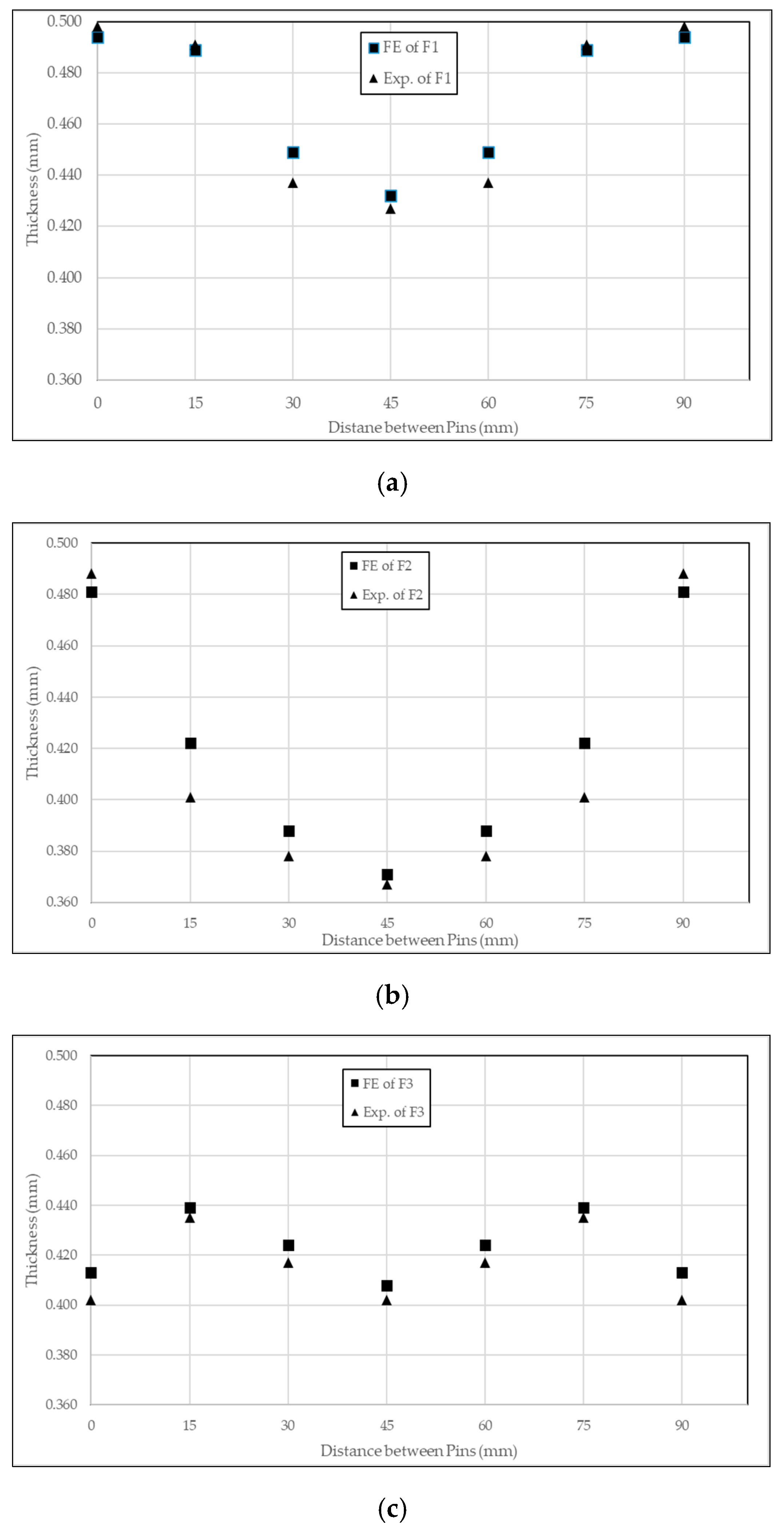
Thinning of the sheets on dimple points was also measured in the finite element model and experimental parts. In Deform 3D, slicing tools were used to measure the points on lines in Figure 16. In the experimental parts, a micrometer was utilized to measure thinning on these points. Form1 and form2 lines were constructed from left to right and the line of form3 was along the diagonal. The measured thickness of the experimental and FE analysis parts of 12 mm forming is shown in Figure 17. For form1 and form2, the highest thinning of sheet metal was measured on point 4, the middle point of the lines. On form1, the thickness of the sheet metal part was obtained as 0.432 mm and 0.427 mm for FE and experimental, respectively. Form2 had 0.371 mm and 0.367 mm thicknesses. In form 3, the highest thinning was observed at points 1, 4, and 7 due to the geometry of the 3D free-form surface. The thickness was acquired as 0.413 mm and 0.403 mm for points 1 and 7 and 0.408 mm and 0.402 mm for point 4. Thickness graphs showed similar trends as were seen in load graphs . Therefore, it was considered that finite element modeling seems to be reliable. The maximum thinning point of form1 is in accordance with the study performed in [21]. In that study, MPF and multi-point forming with individually controlled force-displacement (MPF-ICFD) was performed on 1060 aluminum alloy with 2 mm thickness to give the form similar to form1 in this study. It was concluded that MPF-ICFD proved to generate less thickness variation and thinning.
4. Conclusions
The finite element analysis and experiments were conducted to understand the effect of pin diameter on multi-point forming. This study yielded the followings:
- Different forms of parts were formed in one MPF die by changing the length of pins according to the required part geometry. Thanks to this, it can be said that MPF is cost- and time-effective.
- It was observed that the effect of diameter was directly related to the forming of sheets. The larger diameter of the pin results in higher loads and stress on sheet metal parts.
- In complexly shaped parts, as the pin diameter increases, the material flow is more difficult. This situation showed that a higher load, hence a higher capacity press was required.
- Dimples and thinning of the sheet are unwanted defects but they cannot be completely eliminated in multi-point forming if the workpiece and punch are in contact.
Author Contributions
Conceptualization, M.T. and O.E.; methodology, M.T. and O.E.; software, M.T.; validation, M.T., O.E. and K.E.E.; formal analysis, M.T. and K.E.E.; investigation, M.T.; resources, M.T.; data curation, M.T. and K.E.E.; writing—original draft preparation, M.T. and K.E.E.; writing—review and editing, O.E.; visualization, M.T. and K.E.E.; supervision, O.E.; project administration, O.E. All authors have read and agreed to the published version of the manuscript.
Funding
This work is funded by the University of Gaziantep Scientific Research Projects Governing Unit (BAP) Gaziantep, Turkey (RM.21.01).
Data Availability Statement
Not applicable.
Conflicts of Interest
The authors declare no conflict of interest. The funders had no role in the design of the study; in the collection, analyses, or interpretation of data; in the writing of the manuscript; or in the decision to publish the results.
References
- Li, M.Z.; Nakamura, K.; Watanabe, S. Study of the basic principles (first report research on multi-point forming for sheet metal). In Proceedings of the Japanese Spring Conference for Technology of Plasticity, May 1992; pp. 519–522. [Google Scholar]
- Walczyk, D.F.; Hardt, D.E. Design and analysis of reconfigurable discrete dies for sheet metal forming. J. Manuf. Syst. 1998, 17, 436–454. [Google Scholar] [CrossRef]
- Li, M.; Liu, Y.; Su, S.; Li, G. Multi-point forming: A flexible manufacturing method for a 3-d surface sheet. J. Mater. Process. Technol. 1999, 87, 277–280. [Google Scholar] [CrossRef]
- Li, M.Z.; Cai, Z.Y.; Sui, Z.; Yan, Q.G. Multi-point forming technology for sheet metal. J. Mater. Process. Technol. 2002, 129, 333–338. [Google Scholar] [CrossRef]
- Cai, Z.Y.; Li, M.Z. Finite element simulation of multi-point sheet forming process based on implicit scheme. J. Mater. Process. Technol. 2005, 161, 449–455. [Google Scholar] [CrossRef]
- Liu, C.; Li, M.; Fu, W. Principles and apparatus of multi-point forming for sheet metal. Int. J. Adv. Manuf. Technol. 2008, 35, 1227–1233. [Google Scholar] [CrossRef]
- Qian, Z.R.; Li, M.Z.; Tan, F.X. The analyse on the process of multi-point forming for dish head. J. Mater. Process. Technol. 2007, 187, 471–475. [Google Scholar] [CrossRef]
- Liu, Y.; Li, M.; Ju, F. Research on the process of flexible blank holder in multi-point forming for spherical surface parts. Int. J. Adv. Manuf. Technol. 2017, 89, 2315–2322. [Google Scholar] [CrossRef]
- Abebe, M.; Lee, K.; Kang, B.S. Surrogate-based multi-point forming process optimization for dimpling and wrinkling reduction. Int. J. Adv. Manuf. Technol. 2016, 85, 391–403. [Google Scholar] [CrossRef]
- Zhu, L.; Liang, Q.; Yu, T.; Yuan, P.; Hu, Y. Experimental and theoretical study of constant curvature multi-square punch forming process of strips under follower load. Int. J. Mech. Sci. 2019, 156, 462–473. [Google Scholar] [CrossRef]
- Li, Y.; Shi, Z.; Rong, Q.; Zhou, W.; Lin, J. Effect of pin arrangement on formed shape with sparse multi-point flexible tool for creep age forming. Int. J. Mach. Tools Manuf. 2019, 140, 48–61. [Google Scholar] [CrossRef]
- Xinqi, L.; Shicheng, H. Numerical Simulation and Experimental Research on Multi-Point Forming of Aluminum Alloy Sheets Based on Ultrasonic Vibration. Math. Probl. Eng. 2022, 2022, 7688376. [Google Scholar] [CrossRef]
- Teng, F.; Liang, J.; Wang, S.; Han, Q. Effect of Axial Normal Stress and Bending Moment between Contact and Non-Contact Zone on Forming Accuracy for Flexible Stretch Bending Formation. Metals 2022, 12, 1168. [Google Scholar] [CrossRef]
- Moheen, M.; Abdel-Wahab, A.; Hassanin, H.; Essa, K. Reconfigurable Multipoint Forming Using Waffle-Type Elastic Cushion and Variable Loading Profile. Materials 2020, 13, 4506. [Google Scholar] [CrossRef]
- Tolipov, A.; Hassanin, H.; El-Sayed, M.A.; Eldessouky, H.M.; Alsaleh, N.A.; Alfozan, A.K.; Essa, K.; Ahmadein, M. Multipoint Forming Using Hole-Type Rubber Punch. Metals 2022, 12, 491. [Google Scholar] [CrossRef]
- Borchers, F.; Clausen, B.; Ehle, L.C.; Eich, M.; Epp, J.; Frerichs, F.; Hettig, M.; Klink, A.; Kohls, E.; Lu, Y.; et al. The Influence of Former Process Steps on Changes in Hardness, Lattice and Micro Structure of AISI 4140 Due to Manufacturing Processes. Metals 2021, 11, 1102. [Google Scholar] [CrossRef]
- Engin, K.; Eyercioglu, O. The Effect of the Thickness-to-Die Diameter Ratio on the Sheet Metal Blanking Process. Stroj. Vestn. J. Mech. Eng. 2017, 63, 501–509. [Google Scholar] [CrossRef] [Green Version]
- Semiatin, S.L. Forming and Forging ASM Handbook, 9th ed.; ASM International: Phoenix, AZ, USA, 1996; pp. 796–814. [Google Scholar]
- Smith, L.M.; Averill, R.C.; Lucas, J.P.; Stoughton, T.B.; Matin, P.H. Influence of transverse normal stress on sheet metal formability. Int. J. Plast. 2003, 19, 1567–1583. [Google Scholar] [CrossRef]
- Dib, M.; Ribeiro, B.; Prates, P. Model Prediction of Defects in Sheet Metal Forming Processes. In Proceedings of the Engineering Applications of Neural Networks 19th International Conference, Bristol, UK, 3–5 September 2018; pp. 169–180. [Google Scholar] [CrossRef]
- Jia, B.B.; Chen, G.; Wang, W.W.; Shen, Y.; Gu, Y. Deformation characteristics and forming force limits of multi-point forming with individually controlled force–displacement. Int. J. Adv. Manuf. Technol. 2022, 123, 1565–1576. [Google Scholar] [CrossRef]
Figure 1.
Representation of (a) die set; (b) Constructed bottom die.
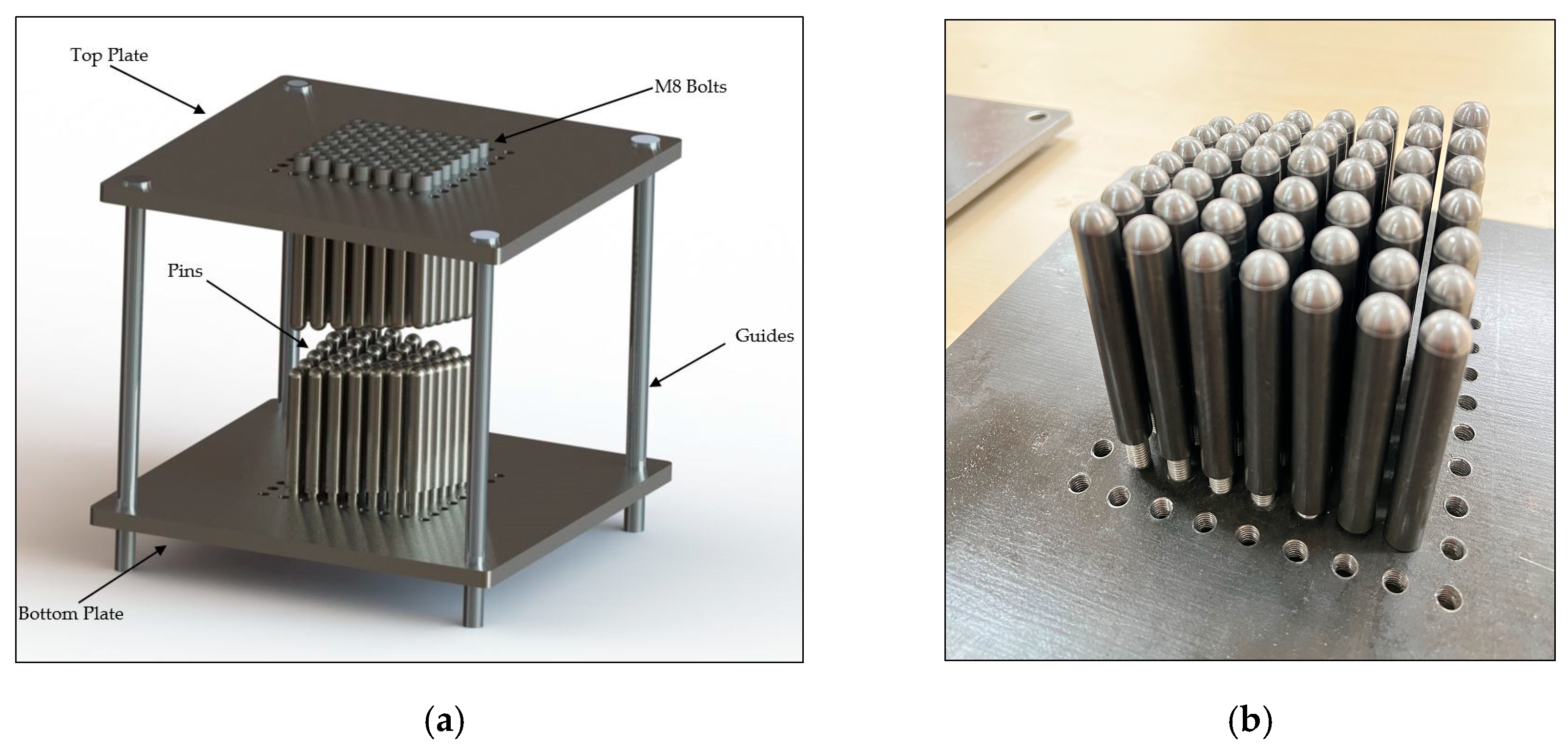
Figure 2.
(a) Pin length; (b) Pin Diameter; (c) Technical drawing of pin.

Figure 3.
Tensile test results.
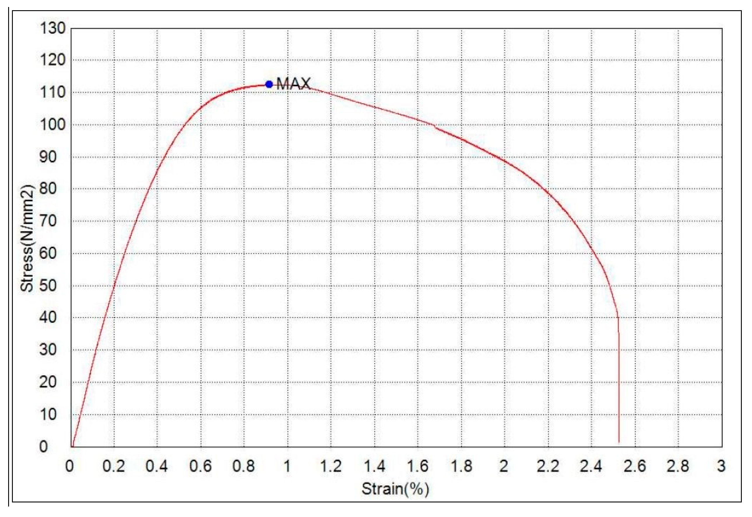
Figure 4.
Aspect of tensile test specimen.
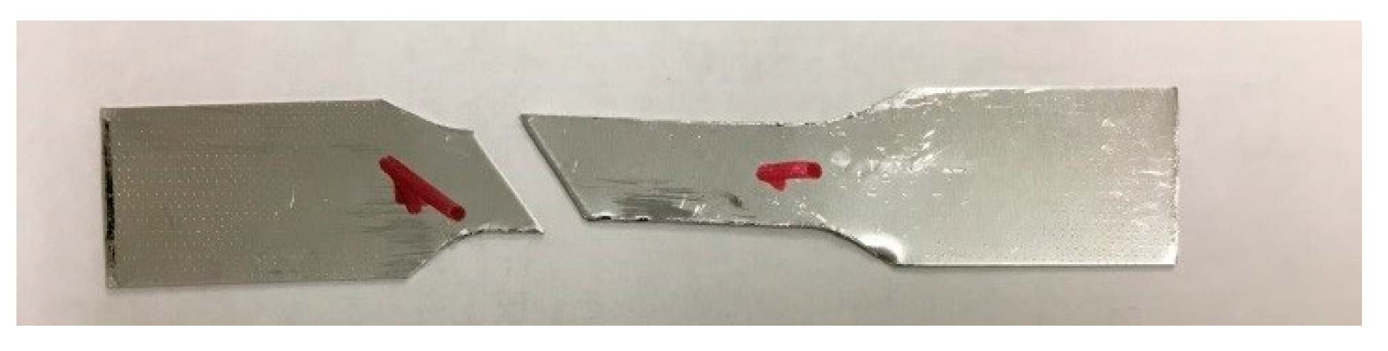
Figure 5.
Geometry of Al1100 parts (a) form1; (b) form2; (c) form3.
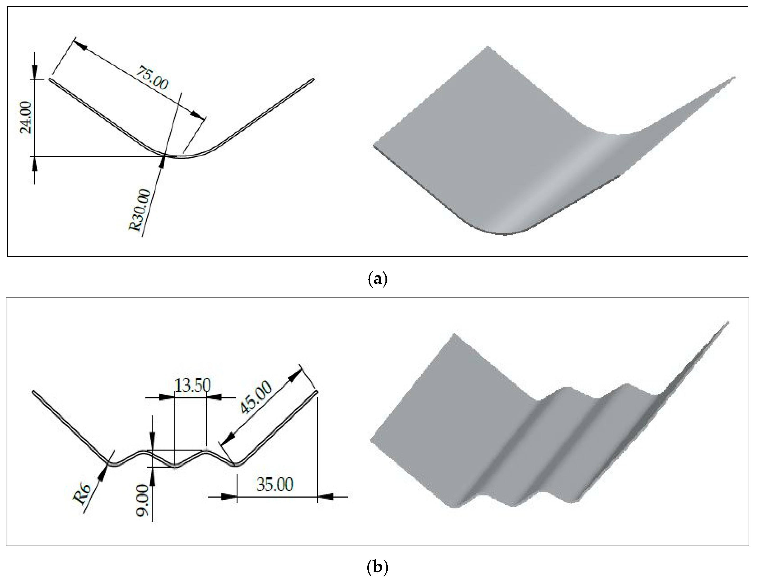
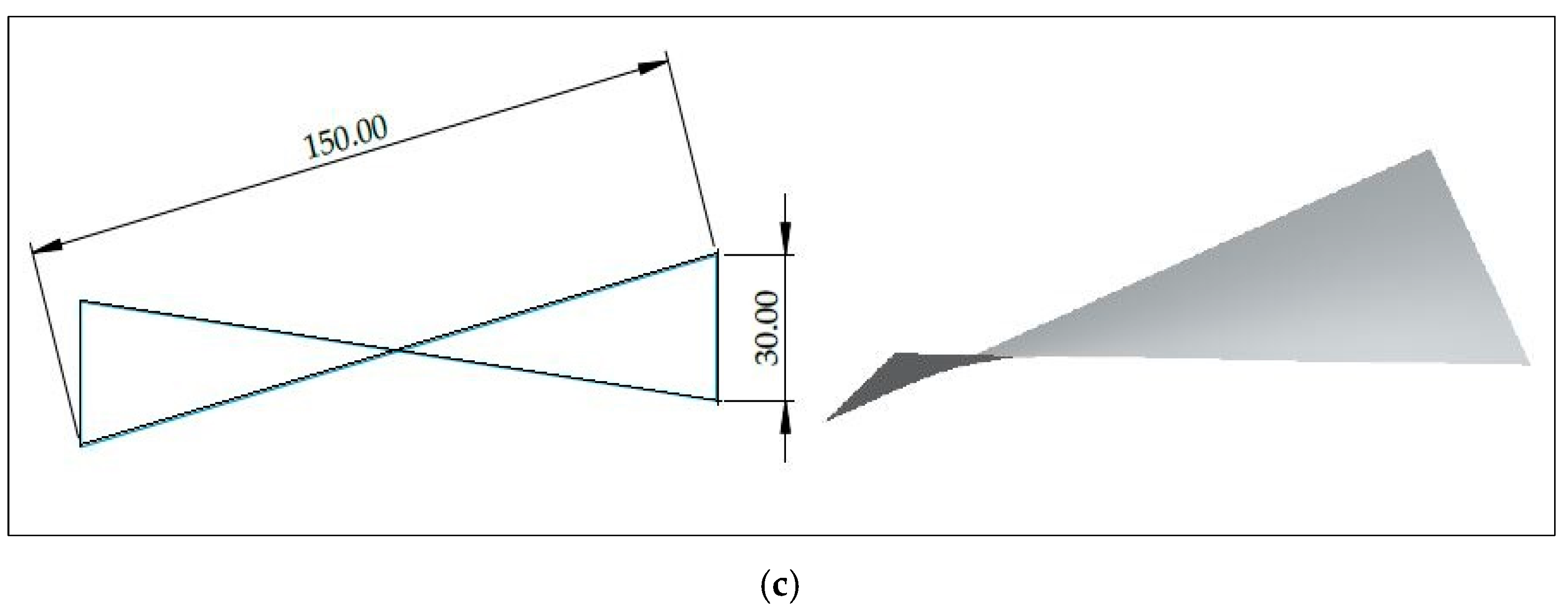
Figure 6.
The photos of the sheets during forming with 12 mm diameter pins (a) form1; (b) form2; (c) form3.
Figure 6.
The photos of the sheets during forming with 12 mm diameter pins (a) form1; (b) form2; (c) form3.
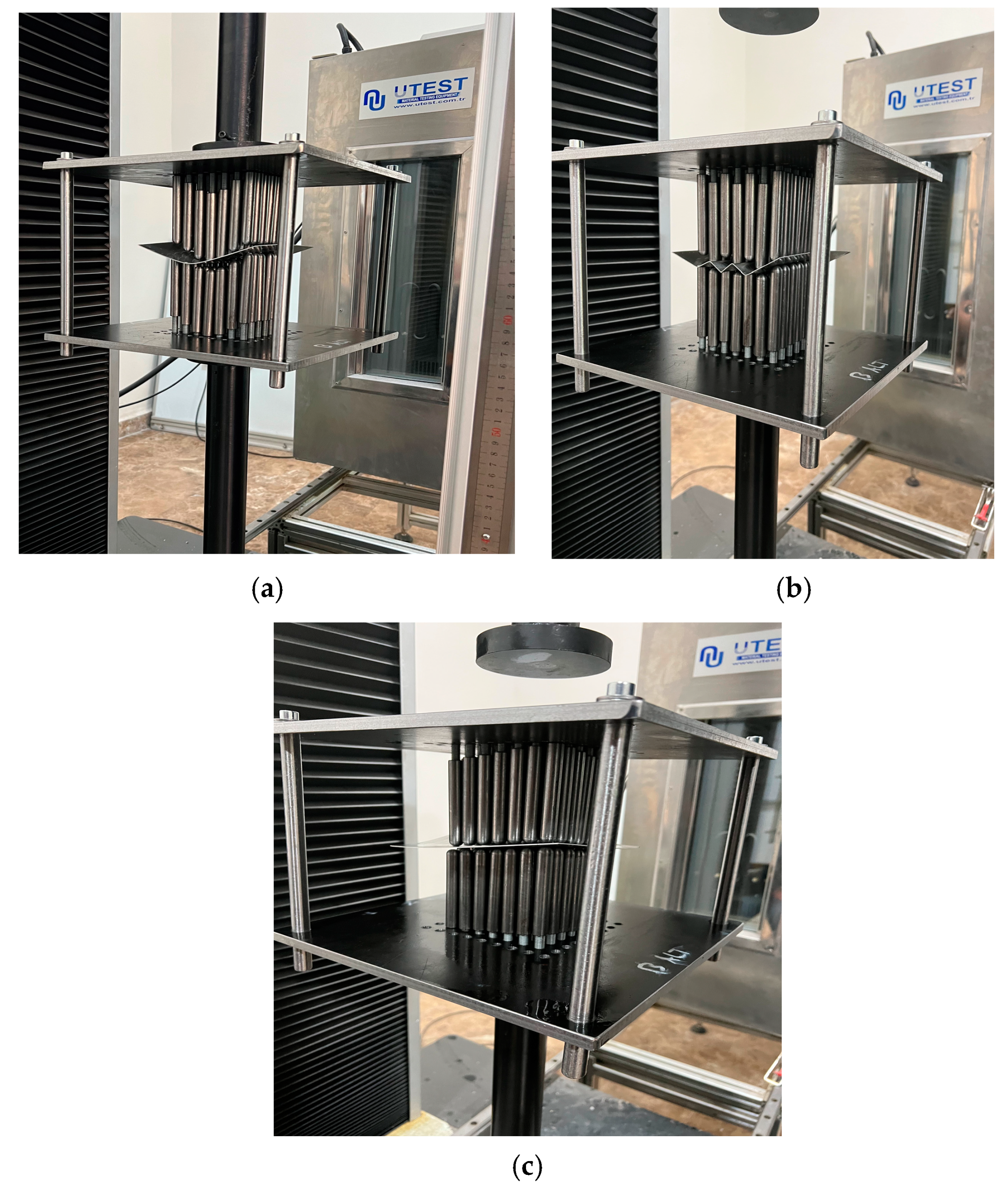
Figure 7.
Flow stress–strain curve of Al 1100.
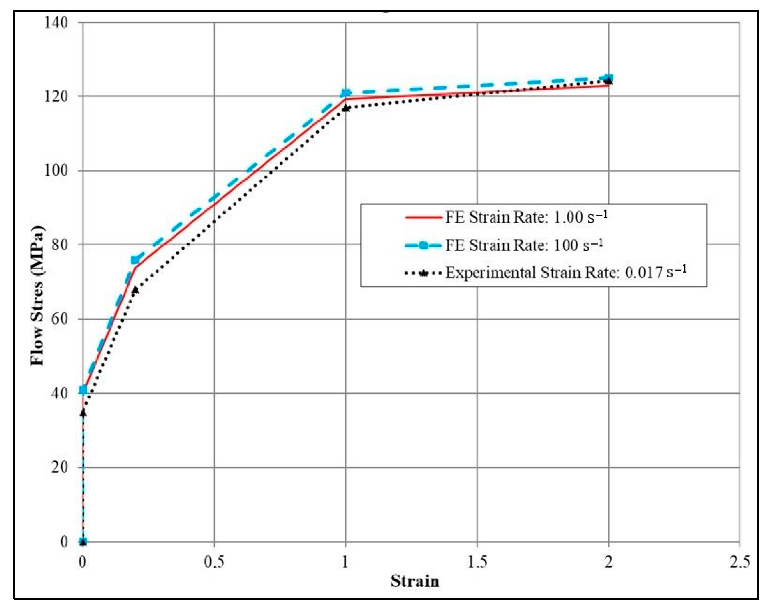
Figure 8.
Effective stress distribution of form1 with a pin diameter of (a) 10 mm; (b) 12 mm; (c) 14 mm.
Figure 8.
Effective stress distribution of form1 with a pin diameter of (a) 10 mm; (b) 12 mm; (c) 14 mm.
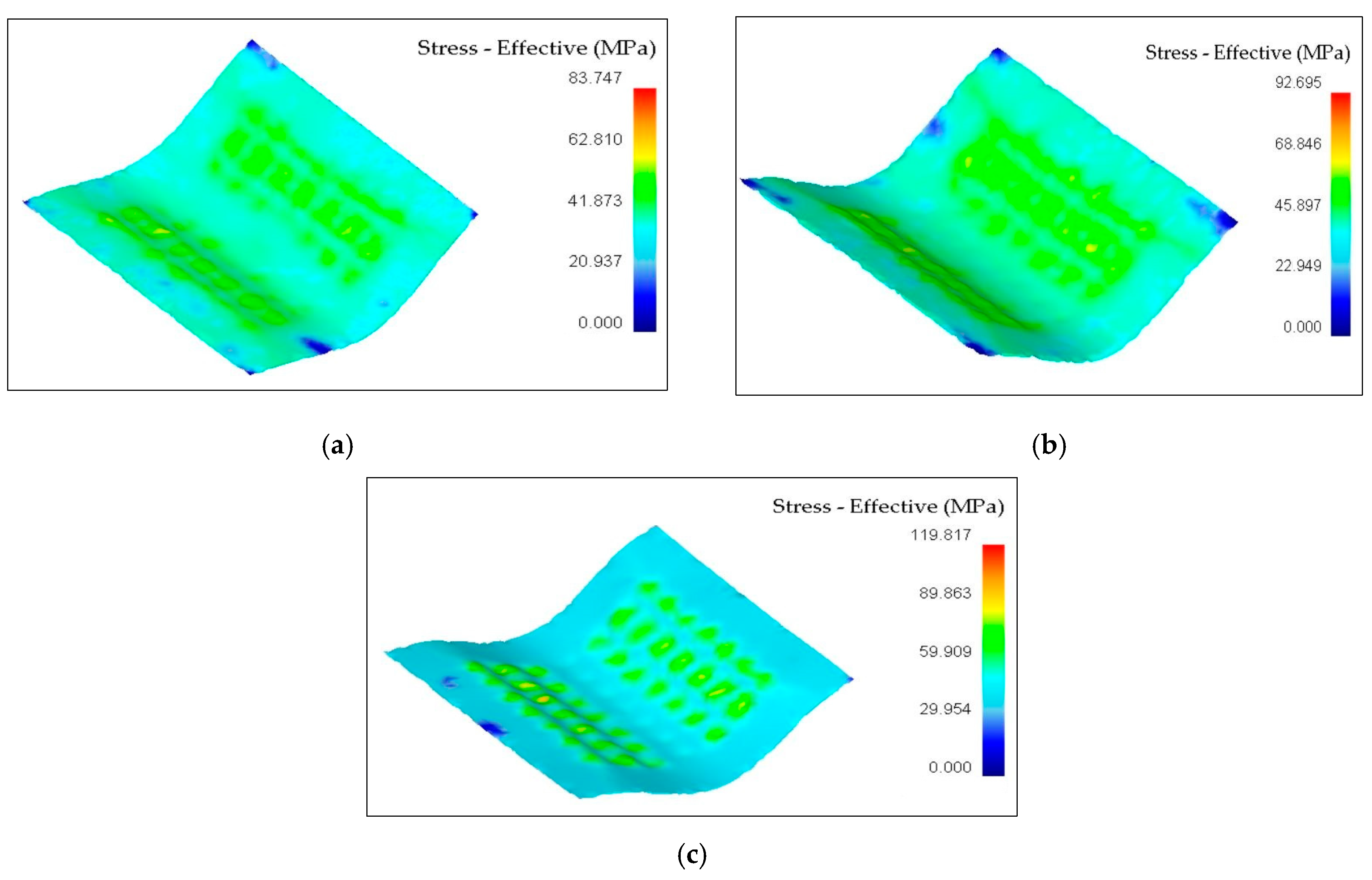
Figure 9.
Effective stress distribution of form2 with a pin diameter of (a) 10 mm; (b) 12 mm; (c) 14 mm.
Figure 9.
Effective stress distribution of form2 with a pin diameter of (a) 10 mm; (b) 12 mm; (c) 14 mm.
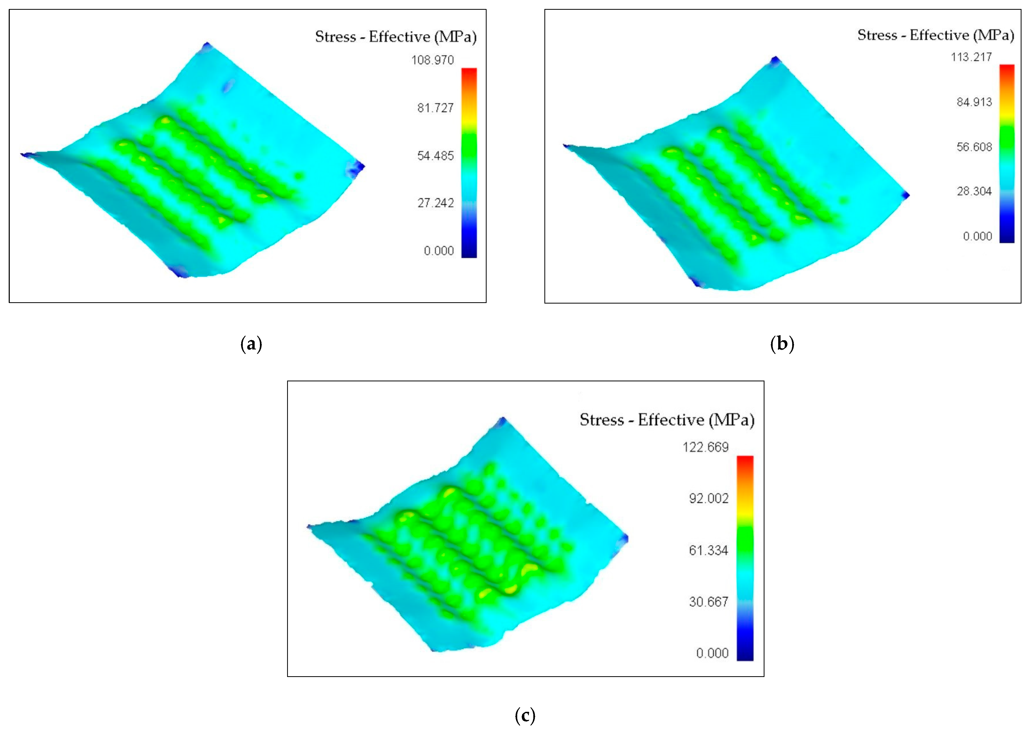
Figure 10.
Effective Stress Distribution of form3 with a pin diameter of (a) 10 mm; (b) 12 mm; (c) 14 mm.
Figure 10.
Effective Stress Distribution of form3 with a pin diameter of (a) 10 mm; (b) 12 mm; (c) 14 mm.

Figure 11.
Damage factors of form1 with (a) 10 mm pins; (b) 12 mm pins; (c) 14 mm pins.

Figure 12.
Damage factors of form2 with (a) 10 mm pins; (b) 12 mm pins; (c) 14 mm pins.
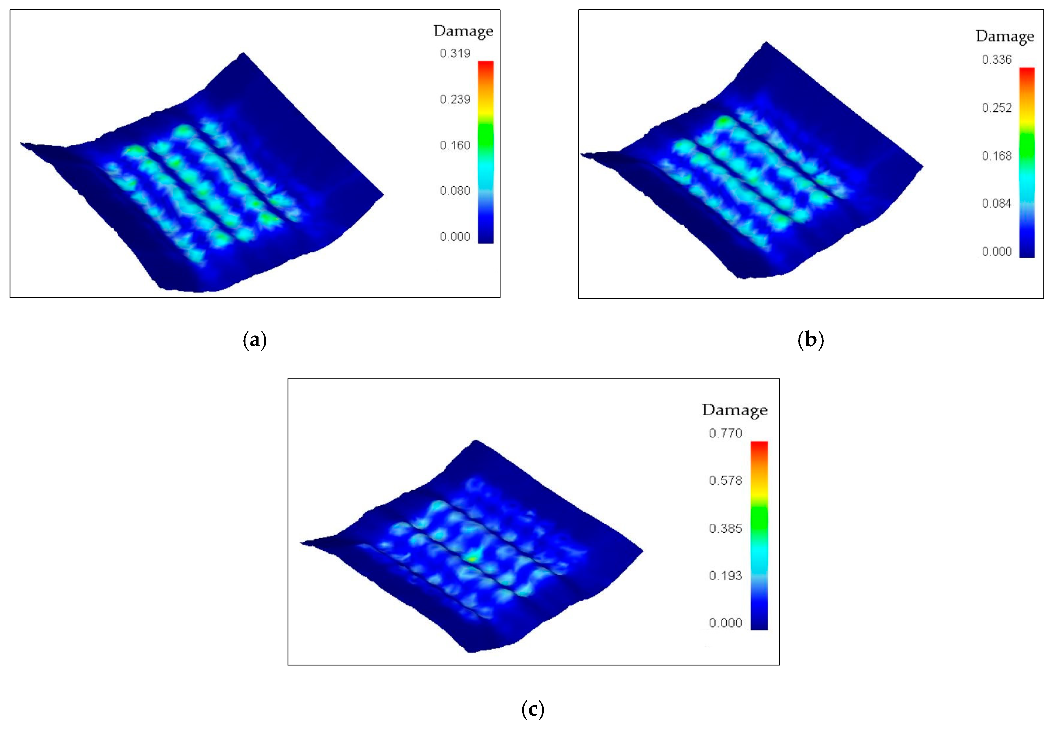
Figure 13.
Damage factors of form3 with (a) 10 mm pins; (b) 12 mm pins; (c) 14 mm pins.
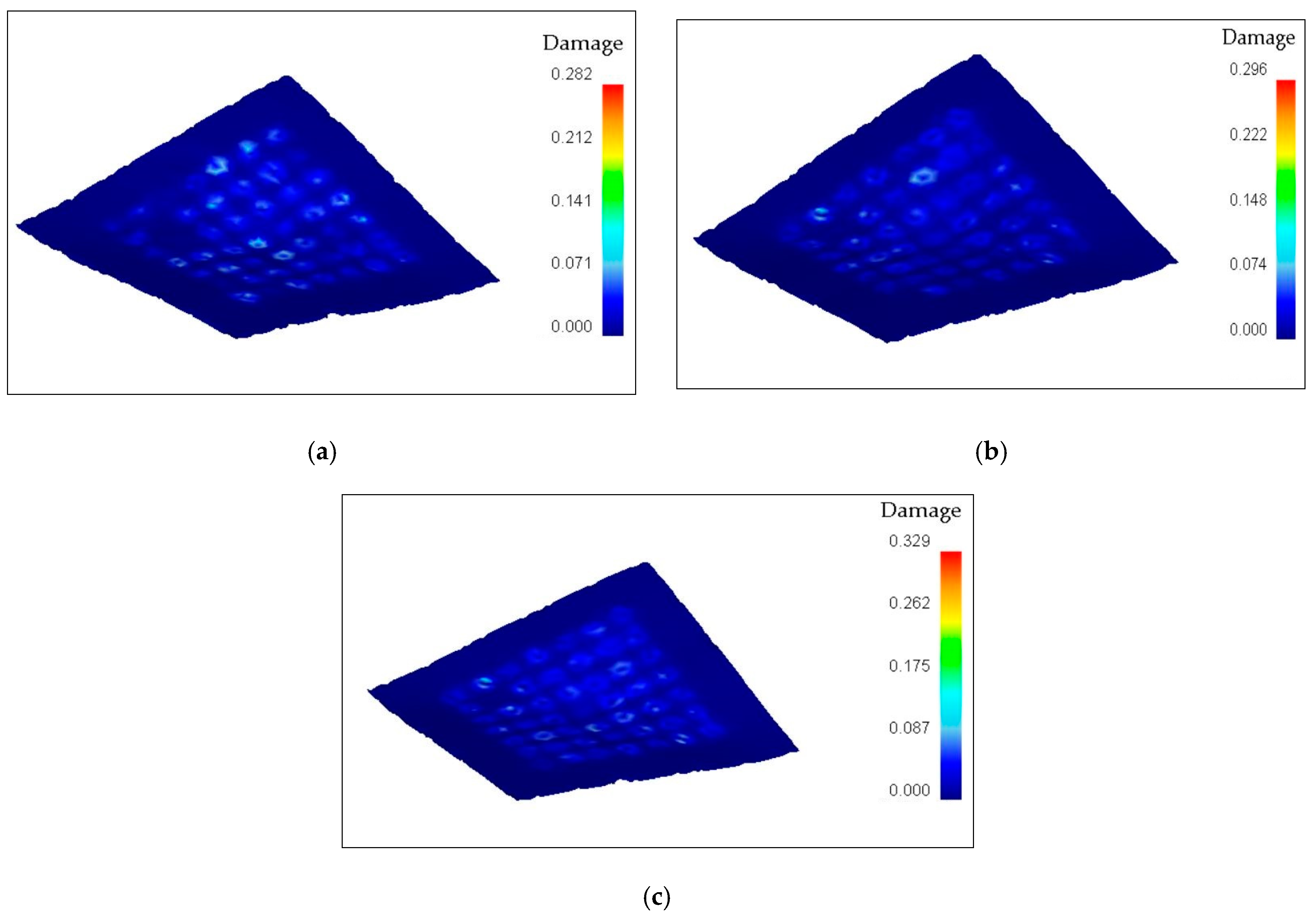
Figure 14.
Forming load–stroke graphs from numerical simulations of (a) form1; (b) form2; (c) form3.
Figure 14.
Forming load–stroke graphs from numerical simulations of (a) form1; (b) form2; (c) form3.
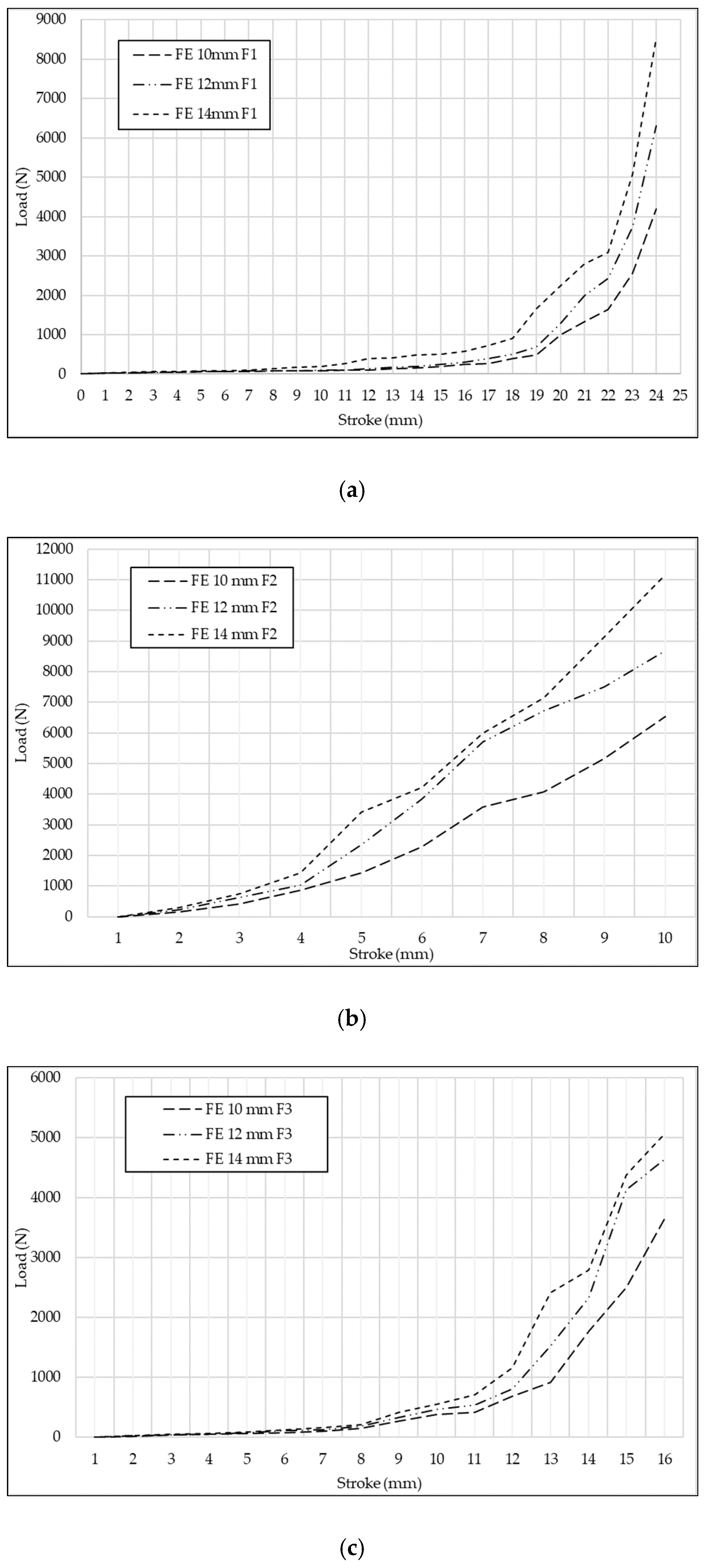
Figure 15.
Comparison of load between simulations and experiments (a) form1; (b) form2; (c) form3.
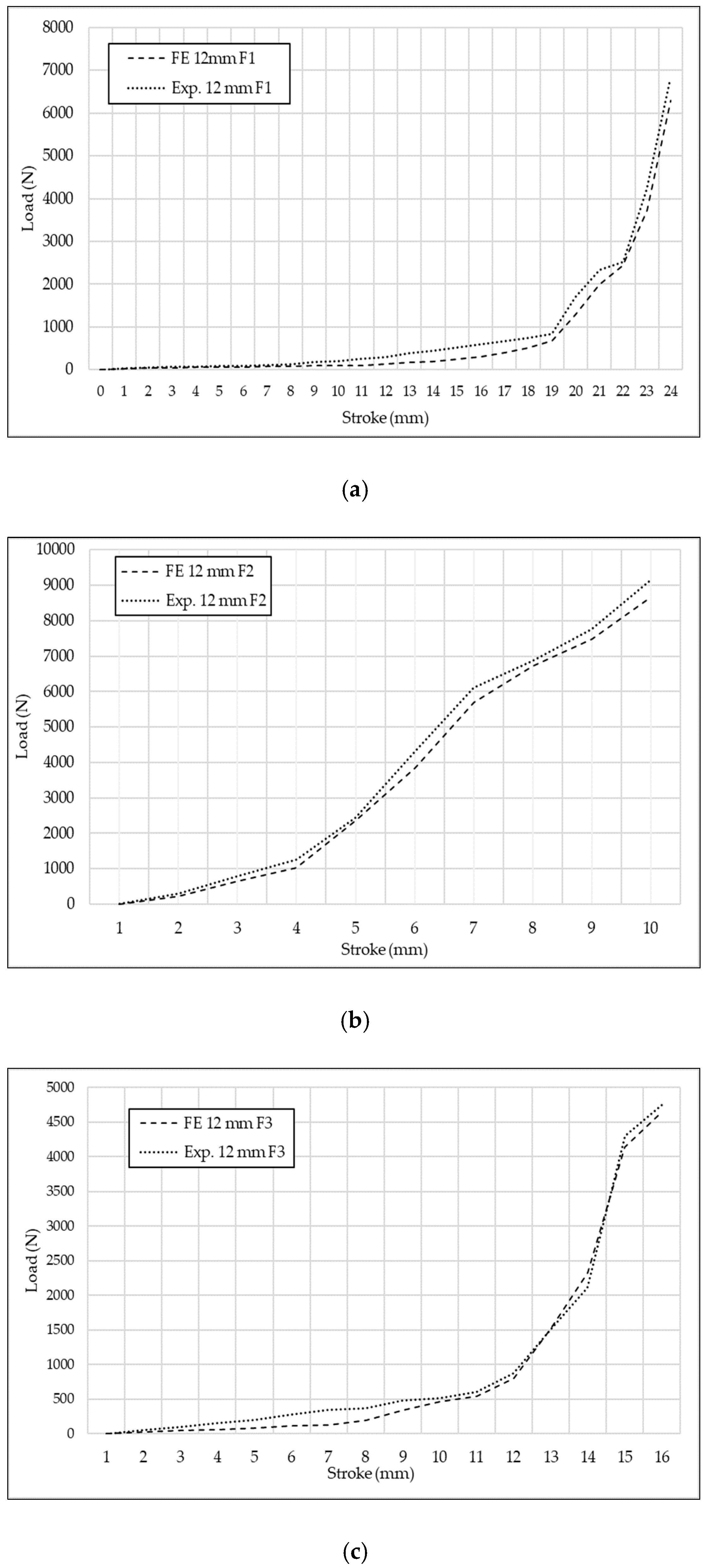
Figure 16.
The parts after experiments (a) form1; (b) form2; (c) form3.

Figure 17.
Comparison of thicknesses between simulations and experiments (a) form1; (b) form2; (c) form3.
Figure 17.
Comparison of thicknesses between simulations and experiments (a) form1; (b) form2; (c) form3.

Table 1.
Chemical composition of the sheet, as supplied.
| Si | Cu | Mn | Zn | Fe | Al |
|---|---|---|---|---|---|
| 0.081 | 0.117 | 0.049 | 0.72 | 0.09 | Balance |
Table 2.
Element and Node Numbers.
| Pin Diameter | Forms | No. of Elements | No. of Nodes |
|---|---|---|---|
| 10 mm | Form1 Form2 Form3 | 17,683 | 6037 |
| 12 mm | Form1 Form2 Form3 | 17,683 | 6037 |
| 14 mm | Form1 Form2 Form3 | 17,683 | 6037 |
Disclaimer/Publisher’s Note: The statements, opinions and data contained in all publications are solely those of the individual author(s) and contributor(s) and not of MDPI and/or the editor(s). MDPI and/or the editor(s) disclaim responsibility for any injury to people or property resulting from any ideas, methods, instructions or products referred to in the content. |
© 2023 by the authors. Licensee MDPI, Basel, Switzerland. This article is an open access article distributed under the terms and conditions of the Creative Commons Attribution (CC BY) license (https://creativecommons.org/licenses/by/4.0/).
Share and Cite
MDPI and ACS Style
Tandogan, M.; Eyercioglu, O.; Engin, K.E. Experimental and Numerical Investigation on Effects of Pin Diameter on Multi-Point Forming. Processes 2023, 11, 387. https://doi.org/10.3390/pr11020387
AMA Style
Tandogan M, Eyercioglu O, Engin KE. Experimental and Numerical Investigation on Effects of Pin Diameter on Multi-Point Forming. Processes. 2023; 11(2):387. https://doi.org/10.3390/pr11020387
Chicago/Turabian StyleTandogan, Mahmut, Omer Eyercioglu, and Kaan Emre Engin. 2023. "Experimental and Numerical Investigation on Effects of Pin Diameter on Multi-Point Forming" Processes 11, no. 2: 387. https://doi.org/10.3390/pr11020387
Note that from the first issue of 2016, this journal uses article numbers instead of page numbers. See further details here.