Article

Improving Exoskeleton Functionality: Design and Comparative Evaluation of Control Techniques for Pneumatic Artificial Muscle Actuators in Lower Limb Rehabilitation and Work Tasks

Electrical Engineering Department, Faculty of Engineering, University of Santiago of Chile (USACh), Santiago 9170022, Chile
*
Author to whom correspondence should be addressed.
Processes 2023, 11(12), 3278; https://doi.org/10.3390/pr11123278
Submission received: 21 October 2023 / Revised: 18 November 2023 / Accepted: 20 November 2023 / Published: 23 November 2023
(This article belongs to the Special Issue Design and Control of Complex and Intelligent Systems)

Abstract

:
The study of lower limbs has become relevant in recent years. Lower limbs have several classifications, but the most widespread categories are robots for patient rehabilitation and robots for work tasks. Two of the main pillars in the development of exoskeletons are actuators and control strategies. Pneumatic artificial muscles are similar to human muscles in their function. This work focuses on this similarity to develop control techniques for this type of actuator. The purpose of this investigation is to design, evaluate, and compare the effectiveness of three different control systems—the proportional–integrative–derivative (PID) system, the sliding mode control (SMC) system, and the fuzzy logic controller (FLC) system—in executing precise trajectory tracking using an exoskeleton and including very realistic dynamic considerations. This study aims to design and implement these controllers and assess their performance in following three distinct trajectories, thereby determining the most efficient and reliable control method for exoskeleton motion. Additionally, the analysis centers on both the response of the controllers to external perturbations and the reaction of the controllers when the time delay inherent to their dynamic is added to the mathematical model. Finally, the results are compared, revealing through the analysis of performance indexes and time response that the FLC is the controller that exhibits the best global results in the tracking of the different trajectories. This work demonstrates that, for the system in question, the action of adding a time delay in the actuator causes the FLC and PID controllers to maintain a similar response, which is obtained without the delay action, in contrast to the system with an SMC controller. However, the same does not occur when including other dynamic factors, such as disturbances external to the system.

Graphical Abstract

1. Introduction

Since its origins, robotics has been intrinsically related to the interaction between humans and machines. Initially, robots were intended to replace human operators in the performance of repetitive and risky tasks and activities that required more precision. In recent decades, scientific–technical advances have made great strides. This has led to increasing contact between humans and robots, allowing robots to interact, help, serve, and explore next to human beings. Thanks to this, robotics is present in several daily life activities, for example, in the industrial, entertainment, and military fields.
Medicine is one of the fields that has benefited the most from the scientific–technical advances associated with robots, which day by day materialize in the manufacturing of tools for assisting medical work and helping patient rehabilitation.
Since the 1970s, robots have been used for rehabilitation purposes. These applications initially were centered on the substitution of lost functions in individuals with physical disabilities through the use of devices such as robot orthosis, workstations, feeding devices, and robotic wheelchairs [1].
The study of robots used for the physical rehabilitation of patients has become crucial. In general, the objective of rehabilitation is to recover the patient from a physical impediment or disability and improve his mobility, functional capacity, and quality of life. Disabilities could be the result of a stroke, an injury, or a neurological condition. In this context, the concept of the exoskeleton arises. An exoskeleton is a structure to be used on the human body as a piece of clothing, i.e., a wearable robot (WR), whether to complement the function of a limb or to completely replace it. Exoskeletons combine human intelligence and machine strength and thus enhance the intelligence of the machine and the power of the human operator. As a result, the human operator can achieve goals that he would not be able to reach on his own [2].
Studies have shown [3,4,5] that one of the most frequent causes of disability is lower limb injuries. These injuries may have different origins, such as car accidents, sport injuries, aging, degenerative and congenital diseases, and unhealthy lifestyles. To improve the quality of life of people who have suffered any of the injuries above, rehabilitation therapies are necessary, as they play a key role in maintaining, recovering, and developing movement in the affected limb. These therapies may consist of exercise and minimal interaction between physiotherapist and patient by means of exoskeletons [6]. There is another type of robot able to add external power to the leg joints through mechanical actuators, which are used in everyday life as walking assistance [7]. It is well known that effective recovery from motor impairment of the lower limbs requires intensive limb training [8]. One of the most widely used exoskeletons is the cyborg-type robot called the Hybrid assistive limb (HAL), which improves and/or increases the body function of a user [5] and helps a person with physical disabilities to move, enabling a torque higher than the usual (Figure 1a). Another widespread exoskeleton used in rehabilitation is Lokomat [9], shown in Figure 1b, a robotic orthotic device that provides variable body weight support and assistance to the patient’s lower limbs when he walks on a treadmill. The exoskeleton known as Motomed letto 2 is another robot that balances the lack of movement in patients prostrated in bed [10]. Patients can use it to train their legs or arms from a bed in passive mode, assisted by a motor, or in active mode, as shown in Figure 1c, preventing muscle atrophy and enabling contracture prophylaxis. The ReWalk exoskeleton, created by someone suffering from paraplegia due to a traffic accident [11], is used to help people with paraplegia. This exoskeleton offers two systems: ReWalk Personal 6.0 for personal use and ReWalk Rehabilitation for use in clinics from the company [12].
The development of new exoskeletons is constantly evolving due to the many challenges in improving their performance, reducing their weight, and increasing their adaptability to users. Although affordability, ease of use, and comfort were prioritized in the past, more advanced exoskeleton improvements can enable the transition from exercise to social interaction and, finally, their use in daily activities [13].
Undoubtedly, the development of control strategies is a relevant topic in the development of exoskeletons. Therefore, different control algorithms have been developed in recent years, from simple solutions with proportional–integrative–derivative (PID) controllers to more complex solutions that use controllers implemented with neural networks.
Currently, there are diverse classifications for control strategies, and one of the most complete was conducted in ref. [14], in which control algorithms were categorized according to the human–robot interaction model, specifically based on:
  • Signals from the human body.
  • Force signals from the interaction between the human being and the exoskeleton.
  • Signals from the exoskeleton.
Human–robot interaction is based on the measurement of signals from the human body, which directly reflect the intention of human movement. Studies have demonstrated that a treatment is effective only when the patient actively contributes to movement [15,16], which is not always the case when robots are guiding a human being in predefined trajectories. To record this information, two sensing techniques are usually employed: electroencephalography (EEG) and electromyography (EMG).
EEG is responsible for capturing the intention of movement, while EMG records muscle intensity, allowing exoskeletons to compensate for muscular activity and perform desired movements. This synergy between both techniques is essential for the effective control of exoskeletons and contributes to the field of assisted robotics. Table 1 presents the main characteristics of these two sensing techniques is presented below.
Increasingly, EEG signals are being employed in the lower limbs to promote active patient participation in rehabilitation, stimulating the corticospinal pathways and facilitating cerebral reorganization post-injury [17]. The SSVEP (steady state visual evoked potential) system streamlines lower limb control through therapist-assigned tasks, during which EEG signals are recorded and processed to interpret user intent [17]. On the other hand, the NeuroRex system combines the Rex exoskeleton with a brain–computer interface (BCI) to enable independent walking, coordinating cerebral and manual control with autonomous robot algorithms [18]. Widely studied EMG signals possess the capability to predict desired movements, even in cases of muscle weakness [19,20]. Additionally, they are used to estimate joint angles and enhance exoskeleton stability [21,22], as well as to predict movement in hemiplegic patients, utilizing EMG signals from unaffected limbs [23].
The utilization of force signals derived from the interaction between individuals and exoskeletons is of paramount importance in the field of exoskeleton control, serving as a fundamental complement to signals originating from the human body. These interaction force signals, stemming from various sources such as user movements and exoskeleton responses, play multifaceted roles in exoskeleton control [12]. They encompass force detection, enabled through the integration of force sensors within exoskeletons, providing real-time feedback on the forces exchanged during physical interaction. Moreover, interaction force signals facilitate force control, allowing algorithms to dynamically adjust the assistance levels and the compliance of exoskeletons in response to detected forces, thereby ensuring safe and effective interaction. Additionally, these signals are pivotal in ensuring safety and collision avoidance, as exoskeletons such as HAL-5 can respond to unusually high forces by activating safety mechanisms or modifying their behavior, thus preventing potential injuries or discomfort [14,24]. Furthermore, the analysis of interaction force signals yields valuable insights into user intentions, movements, and preferences, serving as a foundation for enhancing control algorithms. This, in turn, enables the implementation of adaptive or learning-based approaches for exoskeleton control, ultimately elevating the overall user experience and performance [24].
A critical aspect in the control strategies for exoskeletons lies in the utilization of signals acquired directly from the exoskeletons themselves. This classification underscores the pivotal role of sensor data, encompassing a diverse array of sensors. Encoders and potentiometers deliver angular position information, elucidating joint configurations and movements. Force and momentum sensors, including load cells, facilitate the precise quantification of forces and momenta exerted on joints or contact points. Inertial sensors, notably accelerometers and gyroscopes, furnish data on linear acceleration, angular velocity, and exoskeleton orientation, which are pivotal for comprehending movements and positional alterations. Pressure sensors, occasionally integrated into exoskeletons, discern pressure distribution across user contact surfaces, thereby enabling adaptive responses based on contact forces. Furthermore, the BLEEX (Berkeley lower extremity exoskeleton) [25] exemplifies a control system that exclusively relies on exoskeleton-derived information, eliminating the need for human body signals or interactive forces to predict movement intentions. This approach, while reducing reliance on additional interfaces, demands a robust dynamic model for optimal performance. The amalgamation of these sensor-based signals propels the evolution of exoskeleton control strategies, offering enhanced functionality and adaptability in a myriad of applications.
In ref. [26], the control system of an exoskeleton is classified according to its model system, physical parameters, hierarchy, and usage. However, such systems add additional control challenges [27]. The choice of precise models is paramount [26], aligning with control engineering principles, with dynamic and muscle-based models playing complementary roles [26]. The use of experimental data, such as EMG signals [28], supports model validation, while the application of artificial intelligence, exemplified by wavelet neural networks [28], highlights how computational innovation can enhance accuracy. Furthermore, the consideration of parametric models, such as the “hill-based” model [29], adds depth to muscle-based modeling, enabling predictions of muscular forces based on neuromuscular activity and joint dynamics. It is crucial to remember that the implementation of exoskeletons raises ethical and practical issues [30] that must also be addressed in the research and development of these systems.
Another common controller classification is found in ref. [26], in which controllers are categorized according to physical parameters such as their position, torque/force, and force interaction. In the first case, the control scheme is often used to guarantee that the joints of an exoskeleton turn in the desired angle and is generally implemented as a low-level controller. The second controller of this classification (torque/force) is applied as a high-level controller. Its main objective is to provide adequate assistance to the user when performing a task, with an impedance or admittance controller as a possible controller for the interaction force. The basic notion of an impedance controller is that it accepts the position and produces the force, while the reverse is true for admittance controllers, which accept the force and produce the position.
According to their use, the control system of an exoskeleton can be classified into three primary categories: virtual reality controllers for upper limb applications, teleoperation controllers facilitating remote robotic collaboration, and gait controllers primarily targeting lower limb exoskeletons. Gait controllers, exemplified by the LOPES (power-extremity powered exoskeleton) [31], employ intricate hierarchical control structures to ensure patient safety and optimize therapy outcomes. Innovative approaches, such as sensors and SEA (series elastic actuator)-type controllers [32], electromagnetic drives [33] in the AUTONOMYO exoskeleton, and versatile control interfaces such as EEG and joysticks [34] in the Auto-LEE (autonomous lower extremity exoskeleton), expand the horizons of exoskeleton functionality. Pioneering systems such as BioComEx [35], featuring elastic actuation and variable rigidity, offer promising solutions for rehabilitation and enhanced mobility, while the THKAF (trunk–hip–knee–ankle–foot) device [36] reduces muscular activity, benefiting older individuals and those with disabilities. The Wearable Walking Helper (WWH) [37] demonstrates notable improvements in gait performance, underlining the transformative potential of exoskeletons across diverse domains.
On the other hand, actuators are critical components in the field of exoskeletons. They are responsible for producing motion and providing the necessary force to assist or augment the wearer’s movements. The choice of actuators can significantly impact the design, performance, and usability of an exoskeleton. Several types of actuators are commonly used in exoskeleton systems. Brushless DC motors are widely used in exoskeletons due to their high power-to-weight ratio and efficient operation. They provide torque and angular displacement for joint movements. Additionally, their precise control capabilities are essential for creating natural and smooth motions. Due to their previously mentioned characteristics, ref. [38] highlights that brushless DC motors are the most commonly used actuator in LLEs (lower limb exoskeletons). This type of actuator was recently used in the design of a joint for a pediatric lower limb exoskeleton for children from 6–11 years old, with the orthosis being controlled through state feedback during gait tracking [39]. This type of actuator is also combined with harmonic drive gears in LLEs developed for children with cerebral palsy, as this fusion offers high efficiency. In the case of the three degrees of freedom exoskeleton (hip–knee–ankle) developed by [40], which employs the aforementioned combination, a proportional–derivative (PD) impedance control with gravity compensation is used. Unlike some other types of actuators, such as series elastic actuators, brushless DC motors can be inherently rigid. This can make the exoskeleton’s motion less natural or means the user may perceive less feedback during movement.
Another commonly used type of actuator is the stepper motor. This kind of actuator is used for applications that require precise and controlled angular movements, such as gait assistance or rehabilitation exercises. It operates in discrete steps, allowing for accurate joint positioning. This type of actuator can be controlled in an open loop as long as the motor allows it, as is the case with the exoskeleton developed by [41]. Various control algorithms have been employed in exoskeletons equipped with stepper motor actuators, as in the development of a PID controller using a neuro-fuzzy controller as a compensator [42] for 3-DoF LLE control, which yielded excellent results when compared to a standalone PID controller. Despite being proposed in cases such as [43,44], it’s worth noting that the size and weight of stepper motors must be balanced with their power and torque capabilities, and they can also consume a significant amount of energy, which can be a challenge given the need for exoskeletons to be mobile and battery-operated.
Linear actuators convert rotary motion into linear motion and are often used to create push–pull movements in exoskeletons, as in the knee extension assistance device designed in [45], which was used to perform the function of standing–sitting–standing. This type of actuator allows precise control of speed, position, and force [46,47]. It’s worth noting that in some cases, the range of motion for these actuators is limited, and some of them require regular maintenance.
Hydraulic actuators are known for their high force output, making them suitable for heavy-duty exoskeletons used in industrial or military applications. However, they are less common in wearable exoskeletons due to their size and complexity. Nevertheless, some researchers have employed them, as seen in [48], where they were used in a rehabilitation exoskeleton. For their control, a fault-tolerant neural controller is designed based on a nonlinear observer. In ref. [49], a neural sliding mode repetitive learning control based on a disturbance observer was used for an exoskeleton equipped with this type of actuator. Despite the ability of this actuator to generate high torque, it comes with disadvantages such as the need for more robust control, as well as a requirement for additional components in hydraulic systems to perform their operation.
Recently, actuators known as shape memory alloys (SMAs) have been used in exoskeletons. SMAs are materials that change shape in response to temperature changes. They are employed in some exoskeleton designs to create lightweight and compact actuators for applications such as hand rehabilitation. Despite their primary use in hand applications, they can also be found in some lower limb exoskeletons, as is the case in the knee exoskeleton designed by [50], where a PID controller for the SMA actuator was used. It’s important to note that in these types of actuators, repeated phase transformation cycles can lead to material fatigue over time. Additionally, while heating SMAs to activate their shape memory effect is straightforward, rapid cooling is often necessary for fast actuation cycles. This can be a challenge, especially in compact designs. One of the main challenges posed by SMAs is their use in exoskeletons that require quick responses and high force output.
Series elastic actuators (SEAs) have attracted significant attention due to their ability to maintain low impedance across various frequency ranges [39]. Control strategies for SEAs show remarkable diversity and include the use of proportional–integral (PI) controllers enhanced with speed feedback to improve movement precision and stability [51,52]. Furthermore, the introduction of radial basis function (RBF) neural networks has emerged as a promising approach to enhance the precision of exoskeleton movements, effectively addressing inherent uncertainties in system models [53].
The pursuit of high-performance decoupled torque controllers specifically designed for SEAs is an ambitious undertaking. These controllers must accommodate a wide range of operational scenarios in exoskeletons, dealing with significant parametric uncertainties, nonlinearities, and unmodeled uncertainties in the system. In conjunction with these efforts, the development of robust adaptive algorithms that effectively compensate for these uncertainties is of utmost importance [54].
A distinctive research path is characterized by investigations aimed at enhancing the force precision of SEAs through careful sensor placement and the integration of internal control feedback loops [55]. The inherent benefits of SEAs, including their compact size and cost-effectiveness, make them a preferred choice for lower limb exoskeletons [56]. The pursuit of innovation in SEA technology has given rise to the development of variable rigidity SEAs reinforced by robust controllers based on acceleration, significantly expanding their range of applications, particularly in industrial settings [57]. Safety considerations remain of utmost importance, as exemplified by velocity-sourced series elastic actuators, which demonstrate an ability to mitigate the risk of head injuries during collisions, thus enhancing their suitability for exoskeletons that prioritize safe force and torque transmission [58].
The evolution of SEA technology also encompasses the development of innovative actuator designs, as exemplified by the introduction of the conjugate cylindrical cam-based nonlinear actuator, referred to as N3CSEA. This groundbreaking actuator configuration aims to improve joint performance in knee orthoses, thus contributing to a reduction in energy consumption and addressing the control complexities associated with conventional SEAs [59]. Furthermore, it’s important to note that while SEAs offer advantageous features, they also have certain limitations, particularly their inherent low damping dynamics. To address this limitation, researchers have undertaken efforts to enhance the damping performance of SEAs through a linear control architecture. This architectural innovation involves the implementation of cascade control schemes with the integration of three distinct controllers, namely, proportional–integral controllers, proportional–derivative controllers, and a specialized generalized controller tailored for damping oscillations. To overcome challenges related to frequency–domain constraints, an optimization framework that encompasses both frequency and time-domain objectives is presented. Robust design considerations are essential to account for model imbalances resulting from the underestimation of motor coupling effects. The effectiveness of this advanced control architecture is substantiated through empirical validation, demonstrating improved damping performance in real-world scenarios subject to external disturbances [60].
The choice of actuator type depends on the specific application and requirements of the exoskeleton. Factors such as weight, power consumption, force output, precision, and cost play a crucial role in determining the most suitable actuation system. In many cases, a combination of actuator types may be used to optimize the exoskeleton’s performance and functionality. Additionally, advanced control algorithms and sensory feedback systems are often integrated to ensure safe and natural user interaction with the exoskeleton.
In the healthcare sector, one of the primary benefits associated with exoskeletons is the reduction in clinical costs related to assisting and rehabilitating individuals with neurological and age-related disorders. Actuators, one of the most important components of exoskeletons, also contribute to their reduced weight and improved accessibility. Depending on the control signals they receive, actuators have the capability to generate the necessary forces and torques for carrying out required movements. While pneumatic artificial muscle (PAM)-type actuators are less commonly used in exoskeletons, they offer two essential features: their operation mimics that of a natural human muscle, and they can generate substantial force and torque.
Pneumatic artificial muscles, also known as pneumatic muscles [61] or pneumatic actuators, are gaining attention in the exoskeleton field. PAMs consist of an elastomeric bladder encased in a woven sleeve. When pressurized, they contract and expand, mimicking the behavior of human muscles. PAMs are lightweight, highly compliant, and provide a more natural range of motion, making them suitable for wearable exoskeletons [62]. PAMs may have a slightly slower response time compared to other actuation methods, which can pose a challenge in applications requiring rapid reflexive actions. That is why, in our study, we analyzed the effects of introducing time delay into the control system. This type of actuator tends to be more complex to control than the conventional actuators mentioned earlier.
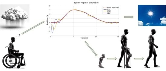
Almost all studies that present a control strategy for a PAM only compare the proposed controller with a PID controller. However, as shown in this work, one of the most employed techniques for commanding this type of actuator is sliding mode control (SMC). Therefore, this work addresses the design and implementation of three controllers —proportional–integrative–derivative controllers, sliding mode controllers, and fuzzy logic controllers (FLCs)—using each of them in the tracking of three different trajectories performed by an exoskeleton. Additionally, the analysis centers on both the response of the controller to external disturbances and the reaction of controllers when the time delay inherent to their dynamic is added to the mathematical model. Finally, the results are compared, revealing through the analysis of performance indexes and time response that the FLC is the controller that exhibits the best global results in the tracking of the different trajectories. There are very few studies that consider and relate topics such as those addressed in this work; additionally, there are even fewer studies that examine control techniques applied to the same exoskeleton and that do not include time delays, external disturbances, data from physical actuators, etc., when addressing this topic in the same work.
This article is divided into five sections. Section 2 reviews the pneumatic muscles used in exoskeletons. Section 3 introduces the dynamics of pneumatic artificial muscles and their antagonistic configuration. Section 4 presents the design of controllers and a comparison of their performances. Lastly, the conclusions of this work are addressed in Section 5.

2. PAMs in Exoskeletons

Actuator selection in the context of exoskeletons depends on crucial considerations of safety and performance. A pivotal concern is the capability to guarantee user safety even in unexpected or challenging situations. According to their actuators, exoskeletons can be classified into exoskeletons driven by motors, by pneumatic artificial muscles, and by a combination of both. In the bibliography consulted, the authors proposed that one of the most important aspects in the design of an exoskeleton is the proper selection of its actuators [38,63,64,65,66].
An actuator can be classified as active or passive depending on the source of its movement. An active exoskeleton uses a source of energy to activate its actuators, and can be electric, pneumatic, or hydraulic. In turn, a passive exoskeleton is a device without an energy source that employs kinematic forces, for example, through the use of springs and dampers.
Most exoskeletons employ direct current (DC) motors to perform movements. However, in recent years, series elastic actuators (SEAs) have been used and diverse studies about their control have been conducted. Contrary to rigid actuators, SEAs contain an elastic element in a series that provides them with several unique properties, including low impedance of mechanical output, tolerance to impact loads, increases in their maximum output power, and passive storage of mechanical energy.
In the case of PAMs, these do not have sliding mechanical parts, and therefore there is no external friction. PAMs have the peculiarity of being exceptionally light and able to reach close power/weight and power/volume relationships compared with other types of actuators. The main limitations of PAMs are high hysteresis and their non-linear force contraction features, which result in a complex design and mechanical control, especially when large ranges of movements and high torques are required. Despite this, their use is more frequent in exoskeletons, as they can more closely simulate the natural behavior of a human muscle.
The study conducted by [67] proposes that of the 52 exoskeletons used as samples for actuation, 66% employ SEAs as actuators, whereas 17% use pneumatic actuation, of which only 3% employ PAMs.

Pneumatic Artificial Muscles

PAMs are inverse bellows, i.e., they contract with inflation. Their force does not only depend on pressure, but also on their inflation state, which constitutes a second spring-like behavior. In addition, they are extremely light because their central element is no more than a membrane; however, they can still transfer the same quantity of energy as cylinders because they operate within the same pressure and volume ranges. Therefore, PAMs are very resourceful when employed to drive exoskeletons and mobile robots.
Inside pneumatic artificial muscles, also known as McKibben pneumatic artificial muscles, fluidic muscles, or biomimetic actuators, is a tubular actuator characterized by a reduction in actuation length when pressurized [68]. The most renowned member of the McKibben muscle family was invented in the 1950s by the physician Joseph L. McKibben, who used it as an orthopedic device for patients with polio. Additionally, PAMs were first commercialized by the Bridgestone rubber company of Japan in the 1980s.
PAMs are significantly lighter actuators characterized by a smooth, accurate, and fast response; additionally, they are able to produce a significant force when completely stretched [69]. As shown in Figure 2, there are numerous actuators of this type.
Some of the multiple advantages of PAM-type actuators are their capacity to provide high-power outputs with relatively light weights and their satisfaction of the need for safety, simplicity, and lightness in human–robot interactions. These characteristics, alongside the fact that PAMs have properties similar to human muscle, make PAMs a promising actuator option for therapeutic devices designed as rehabilitation therapy for patients with degenerative muscle diseases, limb deterioration, or neurological lesions affecting their kinetic abilities. However, PAMs have some important drawbacks, mainly regarding their control. Due to their high nonlinearity, several problems need to be solved, i.e., a difficulty in achieving accurate force and motion control and slow responses to control inputs [70]. Despite these inconveniences, the use of PAMs is increasing in the medical field, especially in rehabilitation. For example, the exoskeleton developed in [71] consists of a hip orthosis equipped with PAMs to assist movements in the lower limbs when a patient has a physical disability.
PAMs find diverse applications in the realm of exoskeletons, including knee rehabilitation, as elucidated in [72]. Here, a sophisticated control algorithm leveraging a neural network is advanced for a one-degree of freedom (DoF) manipulator robot, which serves as an instrumental component in knee rehabilitation efforts. Experimental validation is conducted, underscoring the efficacy of the proposed control strategy across varying patient conditions and therapeutic regimens. Furthermore, PAMs’ versatility extends to innovative motorized orthoses, as highlighted in [73], designed to facilitate intensive home-based gait training for individuals grappling with neurological disorders. In a notable departure, ref. [74] showcases the integration of PAMs within a robotic arm operating with energy assistance, outfitted with rubber PAMs concealed beneath exoskeleton suits to faithfully replicate the actions of bi-articular muscles. Meanwhile, ref. [75] presents the development of a lower limb exoskeleton tailored to fortify and actively aid in gait training. This cutting-edge exoskeleton harnesses the power of PAMs to propel both leg orthoses, ushering in new prospects for gait rehabilitation.
In ref. [76], the development of isokinetic equipment driven by PAMs is presented for hip and knee joint recovery exercises. Another application of this type of actuator is shown in [77], in which a new knee joint rehabilitation device is tested for controlled active movement (CAM) therapy. This system is a re-design of an originally passive CAM device called CAMOped, which consists of a device with an adjustable mechanical resistance thanks to the use of torque-controlled PAMs. These actuators are inherently compatible and can produce both variable resistance and variable rigidity through contraction.
In ref. [78], tracking control for PAM-based rehabilitation is introduced, which employs a multiple-input–multiple-output (MIMO) echo state network (ESN). Due to the intrinsic characteristics of an exoskeleton using PAMs, i.e., nonlinearities, time-varying parameters, hysteresis, unmodelled uncertainties, etc., modelling the system accurately is challenging. Therefore, MIMO ESN is used to approach the dynamic model of the PMA-driven exoskeleton with a nonlinear autoregressive exogenous model. Additionally, the construction of a single layer network (SLN) is proposed to solve the quadratic programming problem over a finite horizon. The employed control strategy is asymptotically stable when the MIMO ESN is able to approximate the dynamics of this type of actuator. Additionally, this control strategy performed better than the traditional approach in trajectory tracking tasks.
In ref. [79], a PAM-based rehabilitation lower limb exoskeleton is proposed. To achieve this, an experimental platform based on the DSPACE (digital signal processing and control engineering) system is developed and a fuzzy adaptive PID controller is applied. The results of these experiments show that adding pre-feedback control based on fuzzy adaptive PID controllers can significantly reduce the response time of the system. Additionally, an elevated level of coordination is noticed between user swing motion and the exoskeleton’s leg.
Robot-assisted therapy significantly helps in the rehabilitation of older people and patients with neurological lesions. Therefore, in ref. [80], a PAM-based exoskeleton is developed that has an innovative design to improve user comfort during walking. To control this exoskeleton, a model-free control strategy known as proxy-based sliding mode control is proposed.
Despite diverse advantages, the non-linearities inherent to PAM hysteresis have a strong influence on the precision of PAM trajectory tracking. Furthermore, systems actuated by PAMs imply high economic costs, although these have decreased in recent years.
The modified Prandtl–Ishlinskii (MPI) model proposed in ref. [81] allows for the characterization of the asymmetrical hysteresis and compensation of PAMs through the use of rapid commutation valves. The parameters of the model proposed are identified using the Levenberg–Marquardt (L-M) method. In turn, cascade control is employed to compensate for non-linear length/pressure hysteresis, thereby reducing costs. Rapid commutation valves based on the inverse MPI model are employed for the control of trajectory tracking. The effectiveness of this control scheme has been demonstrated experimentally.
In ref. [82], a humanoid lower limb exoskeleton (HLLE) activated by PAMs is presented, which is manufactured according to the McKibben principle. In addition, a fuzzy self-tuning PID (FSPID) control based on pulse-width modulation (PWM) is built. Additionally, inertial measurement units (IMU) are installed in specific parts of the HLLE to obtain accurate information concerning its movements and thus provide timely feedback for the control system.
A control strategy for a high conformity lower limb rehabilitation system called AIRGAIT is proposed in ref. [83]. The trajectory tracking control employed in this orthosis is based on a modified calculated pair control that uses a fractional derivative. In addition, this work proposes a new method for the control of robot orthosis compliance, which is employed in an assistance training strategy as necessary.
There is no doubt that PAMs have emerged as a promising actuation technology for powered exoskeletons due to their high power-to-weight ratio, compliance, and customizability compared to traditional actuators such as electric motors. Unlike electric motors, which provide rotary motion, PAMs contract linearly like biological muscles when pressurized with air, enabling more biomimetic and compliant actuation.
A key advantage of PAMs is their inherent compliance and shock absorption capabilities. Exoskeletons designed around rigid actuators can cause discomfort or injury if a collision occurs. In contrast, the natural compliance of PAMs provides a “cushioning” effect that enhances safety. This is especially important for physical human–robot interaction in rehabilitation or assistive applications.
Furthermore, PAMs can be customized in terms of size and contraction force by changing parameters such as diameter and length. This facilitates the modular design of exoskeletons tailored to individual user anatomy and strength requirements. Conventional motors are more limited in scalability and configurability.
However, the nonlinear hysteretic behavior of PAMs presents challenges for precise control. Advanced control strategies are needed to account for the complex dynamics. Two promising trends in PAM control systems are model-based methods such as sliding mode control and model predictive control, as well as data-driven methods such as neural networks. These can provide the robust and adaptive control needed for safe and seamless human–exoskeleton interaction.
In summary, pneumatic artificial muscles hold great promise as actuators for exoskeletons due to their biomechanical compliance, customizability, and high-power density. Continued research into modeling and control will be critical to overcoming their nonlinear dynamics and enabling their adoption in advanced assistive devices. The development of soft wearable robots driven by PAMs could lead to a higher quality of life for many patient populations, according to leading researchers.

3. Dynamics of Pneumatic Artificial Muscles

Several researchers have proposed mathematical models for PAMs. The most representative is the three-element phenomenological model, which includes a spring element, a damping element, and a force element, all of which are connected in parallel, as shown in Figure 3 [84]. The coefficients of each element can be expressed as an internal pressure of the muscle, P. Then, defining x as the variation in the free end position, the motion equation is given by:
M x ¨ + i = 1 m B i P x ˙ i + i = 1 n K i P x i = F P M g
K P = k 0 + k 1 P
B P = b 0 + b 1 P = b 0 i + b 1 i P b 0 d + b 1 d P
F P = f 0 + f 1 P
where x, P, M, Bi(P), m, Ki(P), n, F(P), and g represent the movement of the PAM, the pressure, the load mass, the i-th order of the damping coefficient, the damping polynomial order, the i-th order of the spring constant, the order of the spring polynomial, the contractile force, and the gravitational acceleration, respectively. These coefficients are valid in the following range of pressure values P: 2 ≤ P ≤ 6 bar. In turn, the value of B depends on whether the PAM is being inflated or not, which is represented by the subindexes i (inflation) and d (deflation) [84].
After reorganizing (1), the movement equation for a mass, M, obtained is the following:
F m = M · α = F P B P x ˙ K P x
where F m is the force exerted on a mass, M , and α or x ¨ + g is the acceleration term of the mass, with g = 9.81 m/s2.
For this work, the parameter values in Table 2 were selected, which correspond to the mathematical model of the pneumatic muscles of the company FESTO [85]. The PAM to be used for the simulations is composed of a contractile flexible tube and joints. The contractile flexible tube consists of a rubber membrane and an internal fabric of aramid threads. The membrane hermetically encloses the operating medium. The threads contribute to robustness and force transmission. When internal pressure is applied, the perimeter of the tubular membrane expands. This results in a pulling force and a contraction movement along the longitudinal axis.

Antagonistic Configuration of PAMs

Since PAMs only produce force in one direction, the connection between two muscles is necessary to generate rotational movement. This connection is known as an antagonistic configuration, which is shown in Figure 4. Rotational movement is generated with a transmission via a cable, using a pulley with an r radius and ensuring that the cable is tense enough to avoid sliding and loss of traction.
Considering how people’s movements are produced by their muscles, each of these muscles is assigned, by analogy, to the biceps (b) and triceps (t) groups in order to differentiate the direction of movement. Therefore, the torque produced by these artificial muscles can be represented as follows:
τ = τ b   τ t = b t · r
where τ b and τ t are the torque generated by each artificial muscle and r is the radius of the pulley. Then:
τ b = f b P b b P s ˙ b k b P s b · r
τ t = f t P b t P s ˙ t k t P s t · r
In Equation (7), s b and s t denote the length of the biceps and triceps contraction, respectively. In this way, a positive rotation is obtained through the active force generated by the biceps inflation while the triceps deflates without active contribution to movement. For a negative rotation, the triceps needs to generate the force that drives joint rotation while the biceps remain passive.
The total torque can be expressed in terms of the joint angle, θ , using the following kinematic relationships:
s b = r · θ π 6 ;   s t = r · π 6 θ
In the first stage of the actuation strategy, each PAM is inflated at a positive initial pressure. Subsequently, joint rotation is obtained through the antagonistic control of the PAM pair pressure. A positive/negative rotation of the joint requires an increase/decrease in the Pb pressure of the biceps and a decrease/increase in the Pt pressure of the triceps. Therefore, antagonistic actuation can be formulated as:
P b = P 0 + P , P t = P 0 P
where P0 is the initial pressure and ΔP is the difference in pressure. P0 is used as a variable manipulated in the control of antagonistic pressure. It should be underscored that the antagonistic strategy simplifies movement control since only one control variable, i.e., the difference in pressure, ΔP, is used for activating the joint through two PAMs. Consequently, the dynamics of each biomechatronic joint can be described as:
I l θ ¨ + ζ θ ˙ + τ g θ + d = τ
where Il denotes the inertia of the link, ζ is the viscous friction coefficient in the joint, τ g (θ) denotes the gravity torque, τ is the control input torque, and d represents the unknown external input disturbance that incorporates some external disturbances, such as a load variations or disturbance torque, which are not modeling imbalances, unknown parametric uncertainties, friction non-linearities, etc.
Considering that the PAMs that power the joint are identical, the parameters of the spring elements can be denoted by: k0b = k0t = k0 and k1b= k1t = k1.
From Equations (9) and (10), the following phenomenological model that represents the joint dynamics can be obtained:
I l θ ¨ + ζ + β · θ ˙ + ε · θ + τ g θ + d = δ + σ θ ˙ · u
where u = Δp is the difference in pressure and corresponds to the control input of the close loop. In addition:
ε = 2 r 2 · k 0 + k 1 P 0
β = r 2 · b 0 b + b 0 t + P 0 b 1 b + b 1 t
δ = 2 r · f 1 k 1 π 3 r 2
σ = r 2 · b 1 t b 1 b
where parameter α is part of the elastic rigidity coefficient, ε⋯θ, associated with the spring element of the phenomenological model of three PAM elements, while β is an equivalent friction viscous factor that depends on both the initial pressure and the dampening of the actuator. In turn, parameters δ and σ describe the variability in the torque generated through the damping elements and active force of the actuator’s model.
Thanks to the initial pressure, P0, during joint movement, the values of the parameters defined in Equations (11) and (15) do not vary, with exception of the σ value, which depends on the inflation/deflation phase.
Pneumatic artificial muscle actuators are not free from presenting time delays in their response. According to [87], different perspectives can be considered to add time delays associated with the action of this type of actuator in PAMs:
The time delay from the transfer of control voltage to pressure increase is approximately 5 ms due to valve delay alone.
From pressure increase to voltage increase, there are about 7 ms, mainly because pressure takes time to overcome the threshold.
The voltage rise time (0 to 90%) is 30 ms for full-range transition and 15 ms for medium-range transition, with a fall time (100% to 10%) of 53 ms and 30 ms, respectively; these times are limited by the maximum flow of the valve and the viscosity of the gas in the pipe and its connectors.

4. Design of Controllers and Comparison of Their Performances

To control a PAM in the rehabilitation of the ankle joint, three controllers are designed, namely, proportional–integral–derivative controllers, sliding mode controllers, and fuzzy logic controllers (Fuzzy-PD). Each of these controllers is employed in the tracking of three different trajectories executed by an exoskeleton. The first reference trajectory is a 15° amplitude step; the second reference trajectory is a 10° amplitude sinusoidal signal; and the third reference trajectory is a signal whose amplitude represents the angular variation with which ankle joints move when standing up from and sitting down on a chair. In this way, with the use of cosine functions, the following reference trajectory is obtained [88]:
θ ankle = { 0 t < 1 , 0 1 t < 5 , 7.5 cos ( π 4 t + 3 π 4 ) + 7.5 5 t < 13 , 7.5 cos ( π 8 t 5 π 8 ) + 7.5 13 t < 16 , 0

4.1. Proportional–Integral–Derivative Control

PID controllers are widespread in process automatic regulation. Their success stems mainly from the simplicity of their structure and operation, as they have only three parameters to be tuned. This provides control engineers with a better understanding of processes compared with other advanced control techniques.
The controller tuning rules developed by Ziegler and Nichols constitute the first attempt to design a controller based on information from the processes [89]. Throughout the decades, these controller tuning rules have been modified in order to improve the dynamic performance of processes, even considering the attenuation of the disturbance effects. Likewise, Cohen–Coon consider other criteria for controller tuning [90].
The structure of a PID controller can be defined as:
u = K p e + K i e d t + K d e ˙
where:
  • u is the control signal.
  • e is the difference between the current value and the adjustment point.
  • K p represents the proportional control parameter.
  • K i represents the integral control parameter.
  • K d represents the derivative control parameter.
The modification of the Ziegler and Nichols method for permanent oscillations enables removal of the requirement of taking the system to its stability limit. This method, known as driven oscillation, consists of making the system’s response have oscillations of ¼ of its amplitude, initially employing only the action of the proportional controller. In this way, when the K c value is obtained, which gives the system ¼ attenuated oscillations, the oscillation period is searched for, and the values of T i and T d are calculated through Equations (18) and (19) below, respectively. Subsequently, these values are introduced in the controller, and the K c value is readjusted so the system presents oscillations with ¼ attenuation.
T i = P 1.5
T d = P 6
Applying the methodology above to the system under study, the resulting parameters of the PID controller are Kp = 0.0633, Ki = 0.45, and Kd = 0.02492. Due to the physical characteristics of the PAM used, the controller output is limited to a range from 0 to 6 bar, as this pressure range can enter this type of PAM. Figure 5 shows the responses of the PID controller during the tracking of the three reference trajectories, namely, a 15° amplitude step, a 10° amplitude sinusoidal signal, and a trajectory of an ankle during the activity of standing up from and sitting down on a chair.

4.2. Sliding Mode Control

SMC, also known as non-linear PID control, corresponds to a particular system type of variable structure control (VSC). SMC is a non-linear control method that alters the system dynamics by introducing a discontinuous control signal that forces the system to “slide” along a transversal section of the normal behavior of the system. SMC has two modes: reachability and sliding. Regarding other control methods, SMC offers advantages in the tracking of manipulator robot trajectories, specifically rapid response, good transient performance, a simple control law, and robustness in non-linear systems that vary over time and are subject to external disturbances and/or parameter uncertainty [91,92].
Below, an SMC is designed employing the parameter values of the PID controller presented in the previous subsection, which is used as a sliding surface. In turn, the sliding mode is reached by using the position error of the exoskeleton’s ankle and its derivative with respect to time and multiplying both for the value of parameter ν.
For the design of SMC, the sliding surface is first designed:
S = e ˙ + ν e
where ν is the parameter to be tuned, with the following position error:
e = θ d θ
θd is the desired position and θ the measured position. If Equation (21) is substituted in Equation (20), we obtain:
S = θ d ˙ θ ˙ + ν θ d θ
The time derivative of the sliding surface is:
S ˙ = e ¨ + ν e ˙
Substituting Equation (22) in Equation (23), we obtain:
S ˙ = θ ¨ d + θ ¨ + ν θ ˙ d θ ˙
Solving for θ ¨ in Equation (11) and substituting it in Equation (24), we obtain:
S ˙ = θ ¨ d δ + σ θ ˙ · u ζ + β · θ ˙ ε · θ τ g θ d I l + ν θ ˙ d θ ˙
Since S ˙ = 0 , and considering u = ueq as the system is in sliding mode:
u e q = θ ¨ d + ν θ ˙ d θ ˙ · I l + ζ + β · θ ˙ + ε · θ + τ g θ + d δ + σ θ ˙
Therefore, the obtained SMC is:
U = θ ¨ d + ν θ ˙ d θ ˙ · I l + ζ + β · θ ˙ + ε · θ + τ g θ + d δ + σ θ ˙ + k d s i g n s
where:
u d = k d s i g n s
Additionally, to reduce chattering, u d can be rewritten as:
u d = k d S S + μ
Finally, the full equation of this controller is:
u e q = θ ¨ d + ν θ ˙ d θ ˙ · I l + ζ + β · θ ˙ + ε · θ + τ g θ + d δ + σ θ ˙ + k d S S + μ
where the ν parameter enables adjusting controller performance and, after several computer simulations in which the value of ν is altered, ν = 1.5 delivers a better system response, with k d   = 5 and μ = 0.5 . Figure 6 shows the responses of the SCM during the tracking of reference trajectories.

4.3. Fuzzy Logic Control

FLC enables dividing a complex system into several subsystems based on human expert knowledge about the system. To this end, fuzzy logic provides a mathematical base for dealing with the uncertainties associated with problems from the real world and represents the system dynamics through fuzzy rules such as if-else [93]. Nevertheless, FLC completely depends on an expert designing it, because a fuzzy system can only use knowledge coded into it and is unable to learn on its own; therefore, this type of design is difficult to generalize. In addition, FLC’s main disadvantage lies in the fact that it does not consider system stability [94].
Below, a fuzzy PD controller is designed that has the capacity to logically determine actions to achieve the control goals in the best possible way. To this end, a knowledge base provided by a human expert is used. In this way, using this knowledge, a set of rules is established that describes the behaviors the system should exhibit in any possible operation scenario. The system response to the PID controller is first required to analyze the position error behavior of the exoskeleton’s ankle and its derivative with respect to time.
The rule base is designed employing a Mandami rule structure in which there is a correlation between the input and output linguistic variables. ToolBox from MATLAB (R2022b) Fuzzy is employed to design the fuzzy controller, using two input signals, namely, the error and error derivative, with the pressure that should enter the PAMs as an output.
To design both the error variable and the error derivative, three triangle-type and two trapezoid-like figures were used, while two triangle- and two trapezoid-like figures, plus one Gaussian figure, were employed for output design. In Figure 7, the value ranges defined for each linguistic variable are presented.
Following this procedure, a controller is designed that, through the diverse linguistic variables presented in Table 3, enables representation of the ankle’s behavior during the activity of standing up from and sitting down on a chair.
The controller tuning rules are shown in Table 4. It should be noted that some rules had their relative weight adjusted so they had priority over other rules, thanks to which the performance of the controller improved significantly.
Figure 8 shows the response of the fuzzy PD controller during the tracking of three reference trajectories. As seen in this figure, when using FCL, the resulting trajectories are smooth, which is crucial for the realization of physical exercises by patients in rehabilitation.

4.4. Comparison of Controller Performance

With the purpose of comparing the performance of the controllers designed, each of them is subjected in parallel to each of the three reference trajectories specified above, namely, a 15° step, a 10° amplitude sinusoidal signal, and a signal whose amplitude represents the angular variation with which ankle joints move when standing up from or sitting down on a chair.
In Figure 9, the responses of each of the three controllers are observed, considering the three reference trajectories to which the exoskeleton has been subjected. In the case of the step response (Figure 9a) it is observed that, in the first seconds of operation, the PID controller takes the system up to 6 bar and then stabilizes it around 2 bar. For its part, the response of the SMC controller is the typical one provided by this type of controller, i.e., producing pulses, initially between 0 and 4 bar and then between 3.4 and 0.4 bar; after this, the system stabilizes. However, it is the FLC response that offers the best performance; in fact, from the beginning, the response is close to 2 bar with variations of ±0.05 bar, thus stabilizing the system.
Faced with the sinusoidal signal (Figure 9b), the FLC response continues to be the one with the best performance. For its part, the PID controller, despite producing an impulse towards 0 bar, later manages to maintain a response around 2 bar. For its part, the SMC controller produces behavior similar to that obtained against the step response, but with pulses between 0.3 and 3 bar.
In the case of the ankle trajectory (Figure 9c), the responses of the controllers are similar to those previously described. However, the responses generated by the SMC controller produce greater wear on the actuators due to the pulses to which they are subjected. This implies having to perform maintenance on the actuators more frequently and even replacing said actuators in a shorter time period compared to the responses given by the other two controllers.

4.4.1. Response to a Step Signal and Disturbance Action

Based on the controller responses to the actuation of a 15° amplitude step as a reference presented in Figure 5, Figure 6 and Figure 8, the PID controller is observed to be the controller that generates the highest overshoot of all the assessed controllers. In addition, the PID controller produces several oscillations before its response reaches a steady state. This should not occur during the movement of an exoskeleton, since these oscillations can aggravate the physical health conditions of the patients who uses it, and even cause them injuries. In turn, despite a fast initial response, SMC remains the longest in a transient state compared with the other controllers. However, when FLC is employed, the exoskeleton movement presents the shortest settling time, a smooth response, and no overshoot.
Using each controller, Table 5 presents each exoskeleton response and its values for the maximum overshoot rate (%Mp), rise time (tr), delay time (td), settling time (ts), and root mean square error (RMSE).
Table 6 presents the performance of each controller considering the following performance indices: integral absolute error (IAE), integral square error (ISE), integral time squared error (ITSE), and integral time absolute error (ITAE).
Currently, smart machines are far from real-time adaptability such as that exhibited by human beings when facing changes in the environment, for example, uneven terrain, slopes, mechanical disturbances, weight-lifting, etc. This lack of adaptability represents an important problem when using exoskeletons, not only due to their inability to recover from external disturbances but also due to the different tasks that exoskeletons could be performing, such as changes in gait direction and speed, among others.
Since there is no formal method to establish an analytical border between small and large disturbances, small disturbances can be defined as large enough to cause variation between steps but without leading to the collapse of the user robot system. Disturbances should be distinguishable from the background dynamics of gait, considering ankle/extension typical flexion (about 3°) and the linear rigidity range for ankle flexors and extensors (about 5°) [95]. Therefore, a disturbance of 3° of amplitude is applied to the developed control system. Figure 10 shows the response of each controller to an external disturbance, in this case a −3° step that is applied to the exoskeleton 8 s after initiating movement. SMC is observed to generate small oscillations in its response before taking the exoskeleton back to its steady state. However, although the exoskeleton response with FLC is the slowest to reject the disturbance, the response of FLC is smooth compared to the PID controller and SMC, which reject it quickly. However, fast disturbance rejection can cause diverse physical reactions in patients using exoskeletons. Table 7 presents the performance of each controller when confronted with a disturbance.

4.4.2. Response to a Sinusoidal Signal

When a 10° amplitude sinusoidal signal is applied as a reference, the simulations indicate that the performance of the PID controller should be further analyzed, especially at the beginning of the exoskeleton’s movement, in which even trajectory tracking is opposed to the desired trajectory, which is inadmissible. However, the SMC offers a better response than the PID controller. In turn, the response of the FLC presents excellent results in the tracking of the sinusoidal trajectory.

4.4.3. Response to an Ankle Trajectory

The response of each controller to a signal whose amplitude represents the angular variation at which the ankle joints move when standing up from and sitting down on a chair (Figure 5, Figure 6 and Figure 8) reveal that, unfortunately, the PID controller exhibits a mediocre performance, especially at the beginning of the exoskeleton’s movement, in which the trajectory followed is, at least a couple of times, contrary to expectations. In turn, the SMC offers a better response than the PID controller. Nevertheless, the excellent response of the FLC stands out, as it overlaps with the setpoint.
Table 8 presents the performance of each controller when confronted with a signal that represents movement in the ankle joints when standing up from and sitting down on a chair.

4.4.4. Time Delay Analysis

With the purpose of conducting computer simulations close to reality, a 5 millisecond time delay is added to the mathematical model of the system. This delay represents the time that a PAM takes to conduct the actions of inflating–deflating due to the valves. Figure 11 shows the response of controllers to the action of a 15° step when this delay is added. In this figure, it can be clearly observed that the time delay generates chattering in the system responses, which is quite pronounced when using the SMC. Additionally, compared to the other controllers, settling time considerably increases when using the SMC. However, the PID and FLC controllers maintain similar responses to that of the system without time delay, which can be confirmed through the data presented in Table 9 and Table 10, respectively.
Figure 12 shows the temporal response of the system to a 10° sinusoidal signal considering time delay. It is observed that the system that uses the SMC presents the poorest performance. In this figure, time delay generates chattering in the responses of the system, which is pronounced when using the SMC compared with the PID and FLC controllers. Using each controller, a good tracking of the desired trajectory is observed 3 s after movement begins. The results of the performance assessment of controllers are presented in Table 11. These reveal the superiority of the FLC based on the results of the IAE, ISE, ITSE, and RMSE indexes.
The assessment of system responses to the tracking of desired trajectories from the ankle during the standing and sitting function is presented in Figure 13. Compared to the other controllers, the FLC exhibits the best performance, as shown in the initial response without time delay. The results of the performance assessment of controllers are presented in Table 12.

5. Conclusions

From the references cited and according to the results of this work, it was demonstrated that the use of exoskeletons can improve mobility and safety during the physical rehabilitation of patients, as exoskeletons have biomechanics similar to those of humans, which allows users to move more naturally. Specifically, this paper delved into the morphology, the diverse types of actuators, and the control strategies of exoskeletons used in the rehabilitation of patients with lower limb conditions. Since the use of exoskeletons is increasingly widespread, the strengths and weaknesses in their research field were addressed, and suggestions were made concerning the principal future activities that should be prioritized in the field, such as:
  • A correct selection of both actuators and control strategies that would allow an exoskeleton to offer dynamic performances similar to the movement of human beings.
  • Exoskeletons should be made increasingly ergonomic, compact, efficient, light, durable, and economical.
  • The energy consumption of exoskeletons should be decreased in order to grant them more autonomy and make them more marketable, among other advantages.
Considering the similarity between PAMs and human muscles, three controllers were designed, namely, a PID controller, an SMC, and an FLC. Each of them was employed in the tracking of three different trajectories performed by an exoskeleton. The obtained results were compared through diverse analyses of their temporal responses and performance indices. As a conclusion:
  • The PID controller offers a fast temporal response, but one with overshoot, which can be harmful for a patient performing physical rehabilitation activities. Additionally, considering that trajectories vary over time, this controller considerably worsens its performance. Furthermore, its trajectory tracking is the opposite to the desired trajectory, which is inadmissible.
  • The SMC improves its performance when trajectories are variable, which constitutes the strength of this controller.
  • The FLC delivers the best tracking results in the three trajectories performed by the exoskeleton. Additionally, with this controller, the exoskeleton’s movement presented a small settling time and a smooth response without overshoot.
  • When the system under study is subject to external disturbances, in general, good performances are obtained, especially for the FLC, which presents a smooth recovery from these disturbances.
  • The time delay considered generates chattering in the system responses. However, the PID and FLC controllers maintain good time response parameters, similar to those obtained when time delay is not included. However, with time delay, SMC does not offer good performance.
  • The experimental tests confirm that the increase in time delay in the system produces a reduction in the phase margin and the gain of the closed loop, to the point of causing instability. The effect of time delay is observed in the dynamic response of the system, revealing an increase in overshoot, settling time, and buffered oscillations.

Author Contributions

Conceptualization, C.U. and R.A.; Methodology, C.U. and R.A.; Software, C.U. and R.A.; Validation, C.U. and R.A.; Formal analysis, C.U. and R.A.; Investigation, C.U. and R.A.; Resources, C.U. and R.A.; Data curation, C.U. and R.A.; Writing—original draft preparation, C.U., and R.A.; Writing—review and editing, C.U.; Visualization, C.U.; Supervision, C.U.; Project administration, C.U.; Funding acquisition, C.U. All authors have read and agreed to the published version of the manuscript.

Funding

This research received no external funding.

Data Availability Statement

Data are contained within the article.

Acknowledgments

This work was supported by the Faculty of Engineering of the University of Santiago of Chile, Chile.

Conflicts of Interest

The authors declare no conflict of interest.

References

  1. Xie, S. Advanced Robotics for Medical Rehabilitation; Springer Tracts in Advanced Robotics; Springer International Publishing: Cham, Switzerland, 2016; Volume 108, ISBN 978-3-319-19895-8. [Google Scholar]
  2. Pons, J.L. Wearable Robots: Biomechatronic Exoskeletons|Wiley. Available online: https://www.wiley.com/en-us/Wearable+Robots%3A+Biomechatronic+Exoskeletons-p-9780470512944 (accessed on 8 June 2022).
  3. Ward, E.G.W.; Bodiwala, G.G.; Thomas, P.D. The Importance of Lower Limb Injuries in Car Crashes When Cost and Disability Are Considered. Accid. Anal. Prev. 1992, 24, 613–620. [Google Scholar] [CrossRef]
  4. Shankar, P.; Grewal, V.S.; Agrawal, S.; Nair, S.V. A Study on Quality of Life among Lower Limb Amputees at a Tertiary Prosthetic Rehabilitation Center. Med. J. Armed Forces India 2020, 76, 89–94. [Google Scholar] [CrossRef]
  5. Morioka, H.; Hirayama, T.; Sugisawa, T.; Murata, K.; Shibukawa, M.; Ebina, J.; Sawada, M.; Hanashiro, S.; Nagasawa, J.; Yanagihashi, M.; et al. Robot-Assisted Training Using Hybrid Assistive Limb Ameliorates Gait Ability in Patients with Amyotrophic Lateral Sclerosis. J. Clin. Neurosci. 2022, 99, 158–163. [Google Scholar] [CrossRef]
  6. Muñoz-Reina, J.S.; Villarreal-Cervantes, M.G.; Corona-Ramírez, L.G. Integrated Design of a Lower Limb Rehabilitation Mechanism Using Differential Evolution. Comput. Electr. Eng. 2021, 92, 107103. [Google Scholar] [CrossRef]
  7. Zhang, B.; Wang, S.; Zhou, M.; Xu, W. An Adaptive Framework of Real-Time Continuous Gait Phase Variable Estimation for Lower-Limb Wearable Robots. Robot. Auton. Syst. 2021, 143, 103842. [Google Scholar] [CrossRef]
  8. Mohanta, J.K.; Mohan, S.; Deepasundar, P.; Kiruba-Shankar, R. Development and Control of a New Sitting-Type Lower Limb Rehabilitation Robot. Comput. Electr. Eng. 2018, 67, 330–347. [Google Scholar] [CrossRef]
  9. Neckel, N.; Wisman, W.; Hidler, J. Limb Alignment and Kinematics Inside a Lokomat Robotic Orthosis. In Proceedings of the 2006 International Conference of the IEEE Engineering in Medicine and Biology Society, New York, NY, USA, 30 August–3 September 2016; pp. 2698–2701. [Google Scholar]
  10. Zink, E.K.; Kumble, S.; Beier, M.; George, P.; Stevens, R.D.; Bahouth, M.N. Physiological Responses to In-Bed Cycle Ergometry Treatment in Intensive Care Unit Patients with External Ventricular Drainage. Neurocrit. Care 2021, 35, 707–713. [Google Scholar] [CrossRef]
  11. Bionic Exoskeleton Could Transform Lives of Paraplegics. Available online: https://www.eurekamagazine.co.uk/design-engineering-features/technology/bionic-exoskeleton-could-transform-lives-of-paraplegics/45464/ (accessed on 8 May 2020).
  12. Kwon, S.H.; Lee, B.S.; Lee, H.J.; Kim, E.J.; Lee, J.A.; Yang, S.P.; Kim, T.Y.; Pak, H.R.; Kim, H.K.; Kim, H.Y.; et al. Energy Efficiency and Patient Satisfaction of Gait With Knee-Ankle-Foot Orthosis and Robot (ReWalk)-Assisted Gait in Patients With Spinal Cord Injury. Ann. Rehabil. Med. 2020, 44, 131–141. [Google Scholar] [CrossRef]
  13. Van Dijsseldonk, R.B.; Vriezekolk, J.E.; Keijsers, N.L.W.; Geurts, A.C.H.; van Nes, I.J.W. Needs and Wishes for the Future Lower Limb Exoskeleton: An Interview Study among People with Spinal Cord Injury with Community-Based Exoskeleton Experience. Disabil. Rehabil. 2022, 45, 1139–1146. [Google Scholar] [CrossRef]
  14. Huo, W.; Mohammed, S.; Moreno, J.C.; Amirat, Y. Lower Limb Wearable Robots for Assistance and Rehabilitation: A State of the Art. IEEE Syst. J. 2016, 10, 1068–1081. [Google Scholar] [CrossRef]
  15. Zhou, J.; Yang, S.; Xue, Q. Lower Limb Rehabilitation Exoskeleton Robot: A Review. Adv. Mech. Eng. 2021, 13, 16878140211011862. [Google Scholar] [CrossRef]
  16. Shi, D.; Zhang, W.; Zhang, W.; Ding, X. A Review on Lower Limb Rehabilitation Exoskeleton Robots. Chin. J. Mech. Eng. 2019, 32, 74. [Google Scholar] [CrossRef]
  17. McDaid, A.J.; Song, X.; Xie, S.Q. Brain Controlled Robotic Exoskeleton for Neurorehabilitation. In Proceedings of the 2013 IEEE/ASME International Conference on Advanced Intelligent Mechatronics, Wollongong, Australia, 9–12 July 2013; pp. 1039–1044. [Google Scholar]
  18. Contreras-Vidal, J.L.; Grossman, R.G. NeuroRex: A Clinical Neural Interface Roadmap for EEG-Based Brain Machine Interfaces to a Lower Body Robotic Exoskeleton. In Proceedings of the 2013 35th Annual International Conference of the IEEE Engineering in Medicine and Biology Society (EMBC), Osaka, Japan, 3–7 July 2013; pp. 1579–1582. [Google Scholar]
  19. Wang, B.; Ou, C.; Xie, N.; Wang, L.; Yu, T.; Fan, G.; Chu, J. Lower Limb Motion Recognition Based on Surface Electromyography Signals and Its Experimental Verification on a Novel Multi-Posture Lower Limb Rehabilitation Robots. Comput. Electr. Eng. 2022, 101, 108067. [Google Scholar] [CrossRef]
  20. Fleischer, C.; Reinicke, C.; Hommel, G. Predicting the Intended Motion with EMG Signals for an Exoskeleton Orthosis Controller. In Proceedings of the 2005 IEEE/RSJ International Conference on Intelligent Robots and Systems, Edmonton, AB, Canada, 2–6 August 2005; pp. 2029–2034. [Google Scholar]
  21. Lu, Y.; Wang, H.; Zhou, B.; Wei, C.; Xu, S. Continuous and Simultaneous Estimation of Lower Limb Multi-Joint Angles from sEMG Signals Based on Stacked Convolutional and LSTM Models. Expert Syst. Appl. 2022, 203, 117340. [Google Scholar] [CrossRef]
  22. Layne, C.S.; Malaya, C.A.; Ravindran, A.S.; John, I.; Francisco, G.E.; Contreras-Vidal, J.L. Distinct Kinematic and Neuromuscular Activation Strategies During Quiet Stance and in Response to Postural Perturbations in Healthy Individuals Fitted With and Without a Lower-Limb Exoskeleton. Front. Hum. Neurosci. 2022, 16, 942551. [Google Scholar] [CrossRef]
  23. Yang, X.; Fu, Z.; Li, B.; Liu, J. An sEMG-Based Human-Exoskeleton Interface Fusing Convolutional Neural Networks With Hand-Crafted Features. Front. Neurorobotics 2022, 16, 938345. [Google Scholar] [CrossRef] [PubMed]
  24. Suzuki, K.; Mito, G.; Kawamoto, H.; Hasegawa, Y.; Sankai, Y. Intention-Based Walking Support for Paraplegia Patients with Robot Suit HAL. Adv. Robot. 2007, 21, 1441–1469. [Google Scholar] [CrossRef]
  25. Kazerooni, H.; Racine, J.-L.; Huang, L.; Steger, R. On the Control of the Berkeley Lower Extremity Exoskeleton (BLEEX). In Proceedings of the 2005 IEEE International Conference on Robotics and Automation, Barcelona, Spain, 18–22 April 2005; pp. 4353–4360. [Google Scholar]
  26. Anam, K.; Al-Jumaily, A.A. Active Exoskeleton Control Systems: State of the Art. Procedia Eng. 2012, 41, 988–994. [Google Scholar] [CrossRef]
  27. Büchler, D.; Calandra, R.; Peters, J. Learning to Control Highly Accelerated Ballistic Movements on Muscular Robots. Robot. Auton. Syst. 2023, 159, 104230. [Google Scholar] [CrossRef]
  28. Yang, X.; Lihua, G.; Yang, Z.; Gu, W. Lower Extreme Carrying Exoskeleton Robot Adative Control Using Wavelet Neural Networks. In Proceedings of the 2008 Fourth International Conference on Natural Computation, Jinan, China, 18–20 October 2008; pp. 399–403. [Google Scholar]
  29. Rosen, J.; Fuchs, M.B.; Arcan, M. Performances of Hill-Type and Neural Network Muscle Models—Toward a Myosignal-Based Exoskeleton. Comput. Biomed. Res. 1999, 32, 415–439. [Google Scholar] [CrossRef]
  30. Kiguchi, K.; Hayashi, Y. An EMG-Based Control for an Upper-Limb Power-Assist Exoskeleton Robot. IEEE Trans. Syst. Man Cybern. B 2012, 42, 1064–1071. [Google Scholar] [CrossRef] [PubMed]
  31. Veneman, J.F.; Kruidhof, R.; Hekman, E.E.G.; Ekkelenkamp, R.; Van Asseldonk, E.H.F.; van der Kooij, H. Design and Evaluation of the LOPES Exoskeleton Robot for Interactive Gait Rehabilitation. IEEE Trans. Neural Syst. Rehabil. Eng. 2007, 15, 379–386. [Google Scholar] [CrossRef] [PubMed]
  32. López, R.; Aguilar, H.; Salazar, S.; Lozano, R.; Torres, J.A. Modelado y Control de un Exoesqueleto para la Rehabilitación de Extremidad Inferior con dos grados de libertad. Revista Iberoamericana Automática Informática Industrial RIAI 2014, 11, 304–314. [Google Scholar] [CrossRef]
  33. Ortlieb, A.; Bouri, M.; Bleuler, H. AUTONOMYO: Design Challenges of Lower Limb Assistive Device for Elderly People, Multiple Sclerosis and Neuromuscular Diseases. In Wearable Robotics: Challenges and Trends; González-Vargas, J., Ibáñez, J., Contreras-Vidal, J.L., van der Kooij, H., Pons, J.L., Eds.; Biosystems & Biorobotics; Springer International Publishing: Cham, Switzerland, 2017; Volume 16, pp. 439–443. ISBN 978-3-319-46531-9. [Google Scholar]
  34. He, Y.; Li, N.; Wang, C.; Xia, L.; Yong, X.; Wu, X. Development of a Novel Autonomous Lower Extremity Exoskeleton Robot for Walking Assistance. Front. Inf. Technol. Electron. Eng. 2019, 20, 318–329. [Google Scholar] [CrossRef]
  35. Baser, O.; Kizilhan, H.; Kilic, E. Biomimetic Compliant Lower Limb Exoskeleton (BioComEx) and Its Experimental Evaluation. J. Braz. Soc. Mech. Sci. Eng. 2019, 41, 226. [Google Scholar] [CrossRef]
  36. Ikehara, T.; Tanaka, E.; Nagamura, K.; Tamiya, T.; Ushida, T.; Hashimoto, K.; Kojima, S.; Ikejo, K.; Yuge, L.; Tokyo Metropolitan College of Industrial Technology; et al. Development of Closed-Fitting-Type Walking Assistance Device for Legs with Self-Contained Control System. J. Robot. Mechatron. 2010, 22, 380–390. [Google Scholar] [CrossRef]
  37. Nakamura, T.; Saito, K.; Wang, Z.; Kosuge, K. Realizing Model-Based Wearable Antigravity Muscles Support with Dynamics Terms. In Proceedings of the 2005 IEEE/RSJ International Conference on Intelligent Robots and Systems, Edmonton, AB, Canada, 2–6 August 2005; pp. 2694–2699. [Google Scholar]
  38. Tiboni, M.; Borboni, A.; Vérité, F.; Bregoli, C.; Amici, C. Sensors and Actuation Technologies in Exoskeletons: A Review. Sensors 2022, 22, 884. [Google Scholar] [CrossRef]
  39. Goo, A.; Laubscher, C.A.; Farris, R.J.; Sawicki, J.T. Design and Evaluation of a Pediatric Lower-Limb Exoskeleton Joint Actuator. Actuators 2020, 9, 138. [Google Scholar] [CrossRef]
  40. Sarajchi, M.; Sirlantzis, K. Design and Control of a Single-Leg Exoskeleton with Gravity Compensation for Children with Unilateral Cerebral Palsy. Sensors 2023, 23, 6103. [Google Scholar] [CrossRef]
  41. Iksal; Mulyana, J.; Hartono, T.C.; Fadzlan, M.; Assajjad, A.N. Design of a Lower-Limb Exoskeleton Drive Using an Arduino-Based Stepper Multimotor. Hist. Med. 2023, 9, 434–443. [Google Scholar]
  42. Narayan, J.; Dwivedy, S.K. Towards Neuro-Fuzzy Compensated PID Control of Lower Extremity Exoskeleton System for Passive Gait Rehabilitation. IETE J. Res. 2023, 69, 778–795. [Google Scholar] [CrossRef]
  43. Wankhade, K.; Yadav, P.; Dhamdhere, U.; Ghatake, V.; Kulkarni, V. Exoskeleton Arm for Rehabilitation and Activity Assistance. Int. J. Sci. Res. 2022, 8, 129–133. [Google Scholar]
  44. Fang, Y.; Hou, B.; Wu, X.; Wang, Y.; Osawa, K.; Tanaka, E. A Stepper Motor-Powered Lower Limb Exoskeleton with Multiple Assistance Functions for Daily Use by the Elderly. J. Robot. Mechatron. 2023, 35, 601–611. [Google Scholar] [CrossRef]
  45. Jain, P.; Bera, T.K.; Singla, A.; Isaksson, M. Linear Actuator–Based Knee Exoskeleton for Stand–Sit–Stand Motions: A Bond Graph Approach. Simulation 2022, 98, 627–644. [Google Scholar] [CrossRef]
  46. Ishmael, M.K.; Archangeli, D.; Lenzi, T. A Powered Hip Exoskeleton with High Torque Density for Walking, Running, and Stair Ascent. IEEE/ASME Trans. Mechatron. 2022, 27, 4561–4572. [Google Scholar] [CrossRef]
  47. Dragusanu, M.; Troisi, D.; Villani, A.; Prattichizzo, D.; Malvezzi, M. Design and Prototyping of an Underactuated Hand Exoskeleton With Fingers Coupled by a Gear-Based Differential. Front. Robot. AI 2022, 9, 862340. [Google Scholar] [CrossRef]
  48. Song, C.; Yang, Y. Nonlinear-Observer-Based Neural Fault-Tolerant Control for a Rehabilitation Exoskeleton Joint with Electro-Hydraulic Actuator and Error Constraint. Appl. Sci. 2023, 13, 8294. [Google Scholar] [CrossRef]
  49. Yang, Y.; Dong, X.-C.; Wu, Z.-Q.; Liu, X.; Huang, D.-Q. Disturbance-Observer-Based Neural Sliding Mode Repetitive Learning Control of Hydraulic Rehabilitation Exoskeleton Knee Joint with Input Saturation. Int. J. Control Autom. Syst. 2022, 20, 4026–4036. [Google Scholar] [CrossRef]
  50. Ali, H.F.M.; Kim, Y. Design Procedure and Control of a Small-Scale Knee Exoskeleton Using Shape Memory Alloy Springs. Microsyst. Technol. 2023, 29, 1225–1234. [Google Scholar] [CrossRef]
  51. Ragonesi, D.; Agrawal, S.; Sample, W.; Rahman, T. Series Elastic Actuator Control of a Powered Exoskeleton. In Proceedings of the 2011 Annual International Conference of the IEEE Engineering in Medicine and Biology Society, Boston, MA, USA, 30 August–3 September 2011; pp. 3515–3518. [Google Scholar]
  52. Oh, S.; Kong, K. High-Precision Robust Force Control of a Series Elastic Actuator. IEEE/ASME Trans. Mechatron. 2017, 22, 71–80. [Google Scholar] [CrossRef]
  53. Liao, C.; Ma, H.; Wu, H. Adaptive Control of Series Elastic Actuator Based on RBF Neural Network. In Proceedings of the 2019 Chinese Automation Congress (CAC), Hangzhou, China, 22–24 November 2019; pp. 4365–4369. [Google Scholar]
  54. Lin, Y.; Chen, Z.; Yao, B. Decoupled Torque Control of Series Elastic Actuator With Adaptive Robust Compensation of Time-Varying Load-Side Dynamics. IEEE Trans. Ind. Electron. 2020, 67, 5604–5614. [Google Scholar] [CrossRef]
  55. Sensinger, J.W.; Weir, R.F.F. Improvements to Series Elastic Actuators. In Proceedings of the 2006 2nd IEEE/ASME International Conference on Mechatronics and Embedded Systems and Applications, Beijing, China, 13–16 August 2006; pp. 1–7. [Google Scholar]
  56. Costa, N.R.S.; Caldwell, D.G. Control of a Biomimetic “Soft-Actuated” Lower Body 10dof Exoskeleton. IFAC Proc. Vol. 2006, 39, 785–790. [Google Scholar] [CrossRef]
  57. Sariyildiz, E.; Chen, G.; Yu, H. An Acceleration-Based Robust Motion Controller Design for a Novel Series Elastic Actuator. IEEE Trans. Ind. Electron. 2016, 63, 1900–1910. [Google Scholar] [CrossRef]
  58. Wyeth, G.; Walker, G. Assessing the Safety of a Velocity Sourced Series Elastic Actuator Using the Head Injury Criterion. In Proceedings of the Australasian Conference on Robotics and Automation 2007, Brisbane, Australia, 10–12 December 2007. [Google Scholar]
  59. Sun, Y.; Tang, P.; Zheng, J.; Dong, D.; Chen, X.; Bai, L.; Ge, W. Optimal Design of a Nonlinear Series Elastic Actuator for the Prosthetic Knee Joint Based on the Conjugate Cylindrical Cam. IEEE Access 2019, 7, 140846–140859. [Google Scholar] [CrossRef]
  60. Ghidini, S.; Beschi, M.; Pedrocchi, N. A Robust Linear Control Strategy to Enhance Damping of a Series Elastic Actuator on a Collaborative Robot. J. Intell. Robot. Syst. 2020, 98, 627–641. [Google Scholar] [CrossRef]
  61. Zhong, B.; Cao, J.; McDaid, A.; Xie, S.Q.; Zhang, M. Synchronous Position and Compliance Regulation on a Bi-Joint Gait Exoskeleton Driven by Pneumatic Muscles. IEEE Trans. Automat. Sci. Eng. 2020, 17, 2162–2166. [Google Scholar] [CrossRef]
  62. Zhang, J.-F.; Yang, C.-J.; Chen, Y.; Zhang, Y.; Dong, Y.-M. Modeling and Control of a Curved Pneumatic Muscle Actuator for Wearable Elbow Exoskeleton. Mechatronics 2008, 18, 448–457. [Google Scholar] [CrossRef]
  63. Young, A.J.; Ferris, D.P. State of the Art and Future Directions for Lower Limb Robotic Exoskeletons. IEEE Trans. Neural Syst. Rehabil. Eng. 2017, 25, 171–182. [Google Scholar] [CrossRef]
  64. Toxiri, S.; Näf, M.B.; Lazzaroni, M.; Fernández, J.; Sposito, M.; Poliero, T.; Monica, L.; Anastasi, S.; Caldwell, D.G.; Ortiz, J. Back-Support Exoskeletons for Occupational Use: An Overview of Technological Advances and Trends. IISE Trans. Occup. Ergon. Hum. Factors 2019, 7, 237–249. [Google Scholar] [CrossRef]
  65. Pamungkas, D.S.; Caesarendra, W.; Soebakti, H.; Analia, R.; Susanto, S. Overview: Types of Lower Limb Exoskeletons. Electronics 2019, 8, 1283. [Google Scholar] [CrossRef]
  66. Pérez Vidal, A.F.; Rumbo Morales, J.Y.; Ortiz Torres, G.; Sorcia Vázquez, F.d.J.; Cruz Rojas, A.; Brizuela Mendoza, J.A.; Rodríguez Cerda, J.C. Soft Exoskeletons: Development, Requirements, and Challenges of the Last Decade. Actuators 2021, 10, 166. [Google Scholar] [CrossRef]
  67. Sanchez-Villamañan, M.d.C.; Gonzalez-Vargas, J.; Torricelli, D.; Moreno, J.C.; Pons, J.L. Compliant Lower Limb Exoskeletons: A Comprehensive Review on Mechanical Design Principles. J. Neuro Eng. Rehabil. 2019, 16, 55. [Google Scholar] [CrossRef] [PubMed]
  68. Caldwell, D.G.; Tsagarakis, N. Biomimetic Actuators in Prosthetic and Rehabilitation Applications. Technol. Health Care 2002, 10, 107–120. [Google Scholar] [CrossRef] [PubMed]
  69. Andrikopoulos, G.; Nikolakopoulos, G.; Manesis, S. A Survey on Applications of Pneumatic Artificial Muscles. In Proceedings of the 2011 19th Mediterranean Conference on Control & Automation (MED), Corfu, Greece, 20–23 June 2011; pp. 1439–1446. [Google Scholar]
  70. Zhou, Z.; Wang, Y.; Yu, W. The Role of Pre-Tensioned Springs in 3 Pneumatic Artificial Muscles Driven Joint Mechanisms with Sliding Mode Controllers. Robot. Auton. Syst. 2022, 151, 104017. [Google Scholar] [CrossRef]
  71. Vimieiro, C.B.S. Development of a hip orthosis using pneumatic artificial muscles. In Proceedings of the TMSi 2005, São Paulo, Brazil, 18–19 July 2005. [Google Scholar]
  72. Thanh, T.D.C.; Phuc, T.T. Neural network control of pneumatic artificial muscle manipulator for knee rehabilitation. Technol. Dev. 2008, 11, 14. [Google Scholar]
  73. Knestel, M.; Hofer, E.P.; Barillas, S.K.; Rupp, R. The Artificial Muscle as an Innovative Actuator in Rehabilitation Robotics. IFAC Proc. Vol. 2008, 41, 773–778. [Google Scholar] [CrossRef]
  74. Kadota, K.; Akai, M.; Kawashima, K.; Kagawa, T. Development of Power-Assist Robot Arm Using Pneumatic Rubbermuscles with a Balloon Sensor. In Proceedings of the RO-MAN 2009—The 18th IEEE International Symposium on Robot and Human Interactive Communication, Toyama, Japan, 27 September–2 October 2009; pp. 546–551. [Google Scholar]
  75. Aguilar-Sierra, H.; Yu, W.; Salazar, S.; Lopez, R. Design and Control of Hybrid Actuation Lower Limb Exoskeleton. Adv. Mech. Eng. 2015, 7, 1687814015590988. [Google Scholar] [CrossRef]
  76. Deaconescu, T.; Deaconescu, A. Pneumatic Muscle Actuated Isokinetic Equipment for the Rehabilitation of Patients with Disabilities of the Bearing Joints. In Proceedings of the IMECS 2009, Hong Kong, China, 18–20 March 2009. [Google Scholar]
  77. Martens, M.; Zawatzki, J.; Seel, T.; Boblan, I. A Pneumatic-Muscle-Actuator-Driven Knee Rehabilitation Device for CAM Therapy. In Proceedings of the 2019 41st Annual International Conference of the IEEE Engineering in Medicine and Biology Society (EMBC), Berlin, Germany, 23–27 July 2019; pp. 6237–6242. [Google Scholar]
  78. Cao, Y.; Huang, J.; Tu, X. A Predictive Control for Pneumatic Muscle Actuators Based Exoskeleton by Using MIMO Echo State Network. In Proceedings of the 2019 IEEE 4th International Conference on Advanced Robotics and Mechatronics (ICARM), Toyonaka, Japan, 3–5 July 2019; pp. 408–413. [Google Scholar]
  79. Zhu, S.; Han, Y.; Zhang, M.; Shen, P.; Wu, Z. Research on Fuzzy PID Lower Extremity Exoskeleton Control System Based on Pneumatic Drive. J. Phys. Conf. Ser. 2019, 1311, 012019. [Google Scholar] [CrossRef]
  80. Cao, Y.; Huang, J.; Huang, Z.; Tu, X.; Ru, H.; Chen, C.; Huo, J. Dynamic Model of Exoskeleton Based on Pneumatic Muscle Actuators and Experiment Verification. In Proceedings of the 2018 IEEE-RAS 18th International Conference on Humanoid Robots (Humanoids), Beijing, China, 6–9 November 2018; pp. 334–339. [Google Scholar]
  81. Xie, S.; Mei, J.; Liu, H.; Wang, Y. Hysteresis Modeling and Trajectory Tracking Control of the Pneumatic Muscle Actuator Using Modified Prandtl–Ishlinskii Model. Mech. Mach. Theory 2018, 120, 213–224. [Google Scholar] [CrossRef]
  82. Wan, S.; Yang, M.; Xi, R.; Wang, X.; Qian, R.; Wu, Q. Design and Control Strategy of Humanoid Lower Limb Exoskeleton Driven by Pneumatic Artificial Muscles. In Proceedings of the 2016 23rd International Conference on Mechatronics and Machine Vision in Practice (M2VIP), Nanjing, China, 28–30 November 2016; pp. 1–5. [Google Scholar]
  83. Dao, Q.-T.; Yamamoto, S. Assist-as-Needed Control of a Robotic Orthosis Actuated by Pneumatic Artificial Muscle for Gait Rehabilitation. Appl. Sci. 2018, 8, 499. [Google Scholar] [CrossRef]
  84. Reynolds, D.B.; Repperger, D.W.; Phillips, C.A.; Bandry, G. Modeling the Dynamic Characteristics of Pneumatic Muscle. Ann. Biomed. Eng. 2003, 31, 310–317. [Google Scholar] [CrossRef]
  85. Choi, T.; Choi, B.; Seo, K. Position and Compliance Control of a Pneumatic Muscle Actuated Manipulator for Enhanced Safety. IEEE Trans. Control Syst. Technol. 2011, 19, 832–842. [Google Scholar] [CrossRef]
  86. Merola, A.; Colacino, D.; Cosentino, C.; Amato, F. Model-Based Tracking Control Design, Implementation of Embedded Digital Controller and Testing of a Biomechatronic Device for Robotic Rehabilitation. Mechatronics 2018, 52, 70–77. [Google Scholar] [CrossRef]
  87. Chou, C.-P.; Hannaford, B. Measurement and Modeling of McKibben Pneumatic Artificial Muscles. IEEE Trans. Robot. Automat. 1996, 12, 90–102. [Google Scholar] [CrossRef]
  88. Aguiar, H. Control de un Exoesqueleto para asistir en la Bipedestación y la Marcha de una Persona. 2016. Available online: https://imap.ctrl.cinvestav.mx/~yuw/pdf/DoHipolito.pdf (accessed on 19 November 2023).
  89. Ziegler, J.G.; Nichols, N.B. Optimum Settings for Automatic Controllers. J. Dyn. Syst. Meas. Control 1993, 115, 220–222. [Google Scholar] [CrossRef]
  90. Joseph, E. Cohen-Coon PID Tuning Method: A Better Option to Ziegler Nichols-PID Tuning Method. Comput. Eng. Intell. Syst. 2018, 9, 5. [Google Scholar]
  91. Urrea, C.; Agramonte, R. Evaluation of Parameter Identification of a Real Manipulator Robot. Symmetry 2022, 14, 1446. [Google Scholar] [CrossRef]
  92. Mallem, A.; Nourredine, S.; Benaziza, W. Mobile Robot Trajectory Tracking Using PID Fast Terminal Sliding Mode Inverse Dynamic Control. In Proceedings of the 2016 4th International Conference on Control Engineering & Information Technology (CEIT), Hammamet, Tunisia, 16–18 December 2016; pp. 1–6. [Google Scholar]
  93. Urrea, C.; Saa, D. Design, Simulation, Implementation, and Comparison of Advanced Control Strategies Applied to a 6-DoF Planar Robot. Symmetry 2023, 15, 1070. [Google Scholar] [CrossRef]
  94. Chavoshian, M.; Taghizadeh, M. Recurrent Neuro-Fuzzy Model of Pneumatic Artificial Muscle Position. J Mech Sci Technol 2020, 34, 499–508. [Google Scholar] [CrossRef]
  95. Tucker, M.R.; Shirota, C.; Lambercy, O.; Sulzer, J.S.; Gassert, R. Design and Characterization of an Exoskeleton for Perturbing the Knee During Gait. IEEE Trans. Biomed. Eng. 2017, 64, 2331–2343. [Google Scholar] [CrossRef]
Figure 1. Exoskeletons most used in rehabilitation: (a) the Hybrid assistive limb (HAL), (b) Lokomat, (c) Motomed letto 2, and (d) ReWalk.
Processes 11 03278 g001
Figure 2. Different types of PAMs: (a) McKibben muscle/braided, (b) pleated muscle, (c) Yarlott netted muscle, (d) ROMAC muscle, and (e) Paynter hyperboloid muscle. Reprinted with permission from ref. [69]. 2023, Georgios Andrikopoulos.
Processes 11 03278 g002
Figure 3. Three-element phenomenological model to study the dynamics of the pneumatic muscle. Reprinted with permission from ref. [84]. 2023, Biomedical Engineering Society.
Processes 11 03278 g003
Figure 4. Antagonistic configuration of the artificial pneumatic muscles for one joint. Reprinted with permission from ref. [86]. 2023, Domenico Colacino.
Processes 11 03278 g004
Figure 5. Response of the PID control system to the three reference trajectories.
Processes 11 03278 g005
Figure 6. SMC response to the three reference trajectories.
Processes 11 03278 g006
Figure 7. Membership functions: (a) e, (b) ė, and (c) pressure.
Processes 11 03278 g007
Figure 8. FLC response to the three reference trajectories.
Processes 11 03278 g008
Figure 9. Controller response to different reference trajectories: (a) step response, (b) sinusoidal response, and (c) ankle trajectory response.
Processes 11 03278 g009
Figure 10. Temporal response of an exoskeleton when faced with a disturbance.
Processes 11 03278 g010
Figure 11. Temporal response of an exoskeleton when faced with a step and 5 ms time delay.
Processes 11 03278 g011
Figure 12. Temporal response of an exoskeleton when faced with a sinusoidal signal with a 5 ms time delay.
Processes 11 03278 g012
Figure 13. Temporal response of an exoskeleton when faced with a signal that represents ankle movement with a 5 ms time delay.
Processes 11 03278 g013
Table 1. Characteristics of the signals delivered by EEG and EMG.
CharacteristicsEEGEMG
Measuring methodMeasures the electrical activity of the brainMeasures the electrical activity of muscles
InvasivenessNon-invasiveInvasive or semi-invasive
Spatial resolutionRelatively poorHigh (at the muscle level)
Time resolutionHighModerate
Information measuredBrain activityMuscle activity
Table 2. Parameters for the antagonist configuration of a PAM from FESTO MAS-20-200N.
ElementParameterValueMeasurement Unit
Spring element k 0 4.82[N/m]
k 1 131[N/m/bar]
Damping element b 0 i   b 0 d 1.22 (1.31)[N/m/s]
b 1 i   b 1 d 1.35 (−2.30)[N/m/s/bar]
Force element f 0 14.89[N]
f 1 20.90[N/bar]
Table 3. Definition of FLC linguistic variables.
ErrorError DerivativeController Response
Negative (N)Negative (N)Very small (VS)
Zero (Z)Zero (Z)Small (S)
Positive (P)Positive (P)Work zone (WZ)
Negative small (NS)Negative small (NS)Big (B)
Positive small (PS)Positive small (PS)Very big (VB)
Table 4. Controller rules.
e/deNNSZPSP
N VSSVSVSVS
NS VSSSVSVB
Z VSSWZBVB
PS VSSBBVB
P VSSBBVB
e/de NNSZPSP
Table 5. Time response parameters of the exoskeleton.
Controller%MptrtdtsRMSE
PID26.0000.6960.0562.034.6117
SMC13.271.22150.46443.9582.6233
FLC0.00121.4560.48411.94891.074
Table 6. Performance indices of the controllers designed for a step.
PIDFLCSMC
IAE8.6539.9312.38
ISE61.5374.7367.27
ITAE5.946.82517.57
ITSE22.7524.6234.49
Table 7. Performance indices of designed controllers when confronted with a disturbance.
PIDFLCSMC
IAE11.920.0454.469
ISE63.520.0376.426
ITAE26.981.7876.886
ITSE38.190.0695.707
Table 8. Performance indices of designed controllers when confronted with a signal that represents ankle movement.
PIDFLCSMC
IAE8.9130.4954.508
ISE62.970.0156.775
ITAE7.564.0797.627
ITSE26.910.1315.529
Table 9. Time response parameters of the exoskeleton.
Controller%MptrtdtsRMSE
PID25.000.6980.0462.082.08
SMC42.750.7410.51014.982.24
FLC1.681.310.4041.572.20
Table 10. Time response parameters of the exoskeleton.
PIDFLCSMC
IAE8.43710.1514.94
ISE57.9172.0976.35
ITAE5.9015.5646.92
ITSE22.3223.9558.01
Table 11. Time response parameters of the exoskeleton.
PIDFLCSMC
IAE9.954.9939.25
ISE62.072.0039.83
ITAE18.4340.5737.96
ITSE27.6316.9146.89
RMSE2.430.351.92
Table 12. Time response parameters of the exoskeleton.
PIDFLCSMC
IAE9.954.9939.25
ISE62.072.0039.83
ITAE18.4340.5737.96
ITSE27.6316.9146.89
RMSE2.430.351.92
Disclaimer/Publisher’s Note: The statements, opinions and data contained in all publications are solely those of the individual author(s) and contributor(s) and not of MDPI and/or the editor(s). MDPI and/or the editor(s) disclaim responsibility for any injury to people or property resulting from any ideas, methods, instructions or products referred to in the content.

