

Dependency of Pressure Expression towards Formation Pressures during Drilling Operations in Hydrocarbon Wells and Suitable Choice of Pressure Control Method
 , ,
, ,
Abstract
:1. Introduction
2. Methods of Work
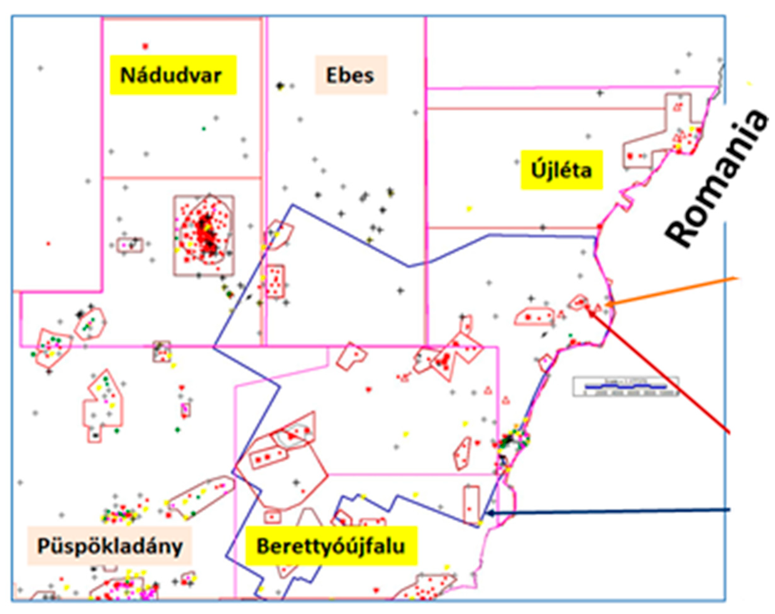
Study Area (Data Summary)
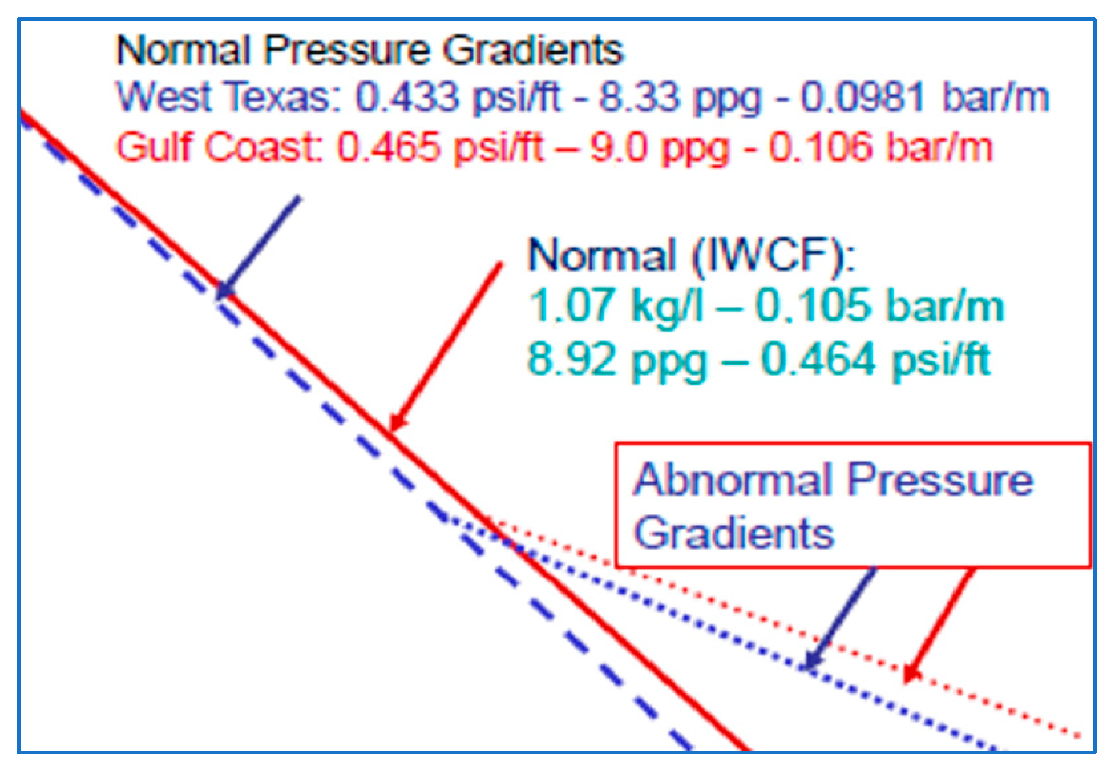
- Pressure Gradient
- Hydrostatic and Hydrodynamic Pressure
- Abnormal Formation Pressure
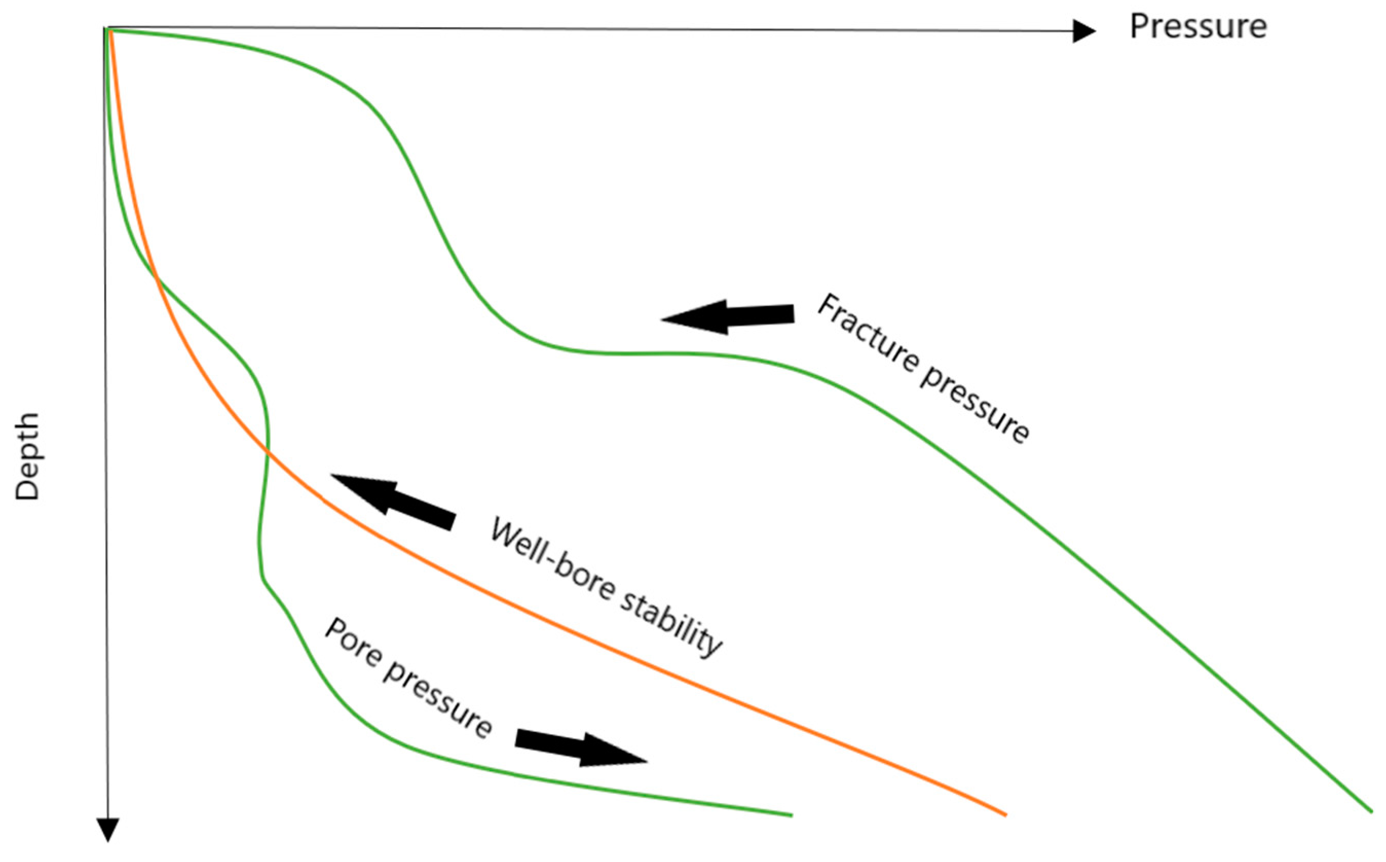
- Formation Fracture Pressure
- -
- Fracturing Pressure (bar);
- -
- Fracture gradient (bar/m);
- -
- Equivalent mud weight (kg/L).
- Formation Integrity Tests (FIT Test)
- -
- The formation type will greatly influence the values of fracture gradient present in a well;
- -
- Some lithologies will exhibit elastic or plastic behavior, some rupture;
- -
- The magnitude of stress required to cause a formation.
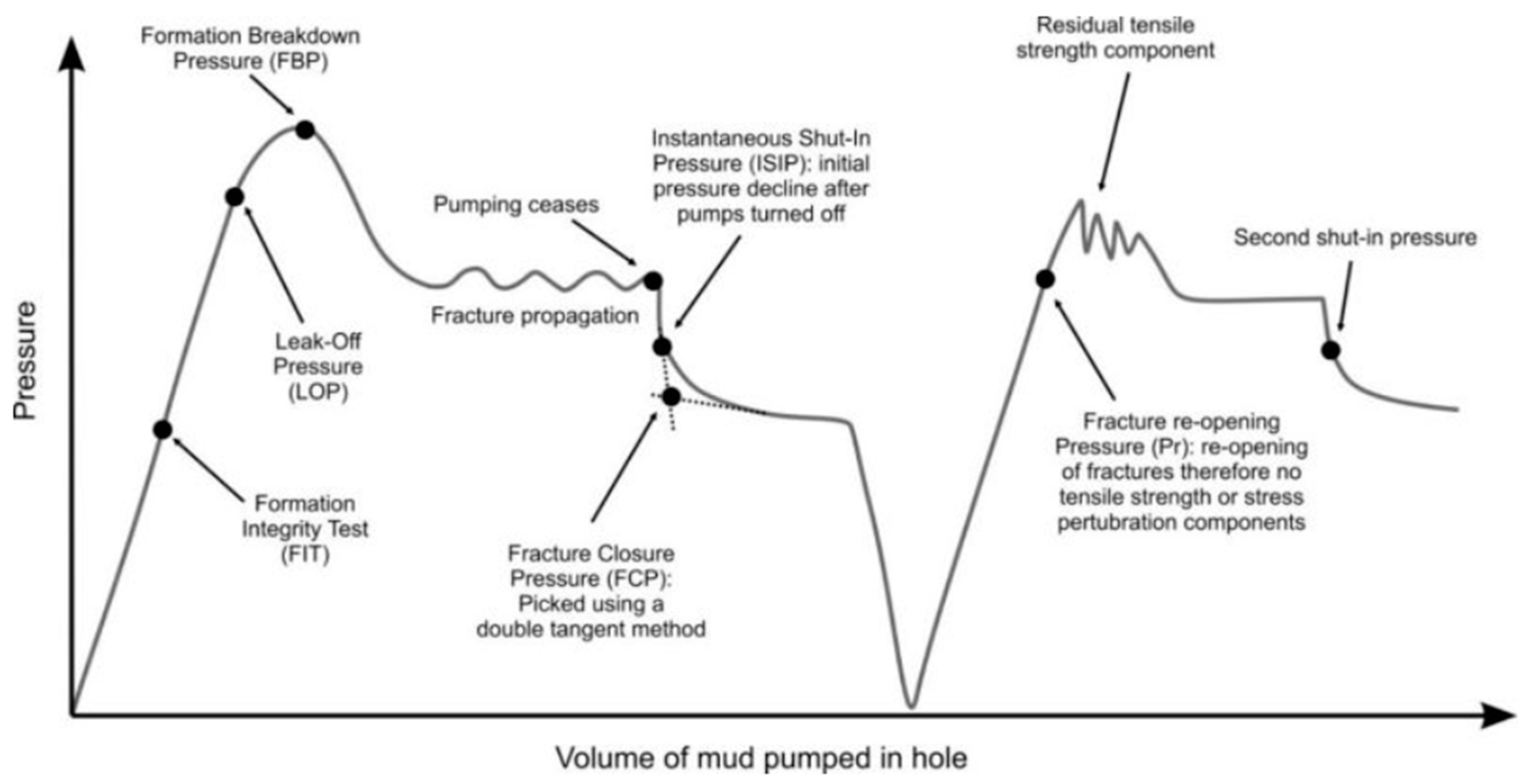
- Leak-Off Test
- Conducting Leak-Off Test
- (1)
- Circulate the hole to have same mud density;
- (2)
- P/U a bit into the casing shoe;
- (3)
- Close the BOP;
- (4)
- Through the cement pump, pump down no higher than 80 L/min, and preferably at about 40 L/min;
- (5)
- On a graph, plot the fluid pumped in 40 L/min increments versus drill pipe pressure until the formation starts to take fluid, at this point, the pressure will continue to rise, but at a slower rate;
- (6)
- Repeat the test to verify the point at which the formation just starts to take fluid; this point is leak-off pressure.
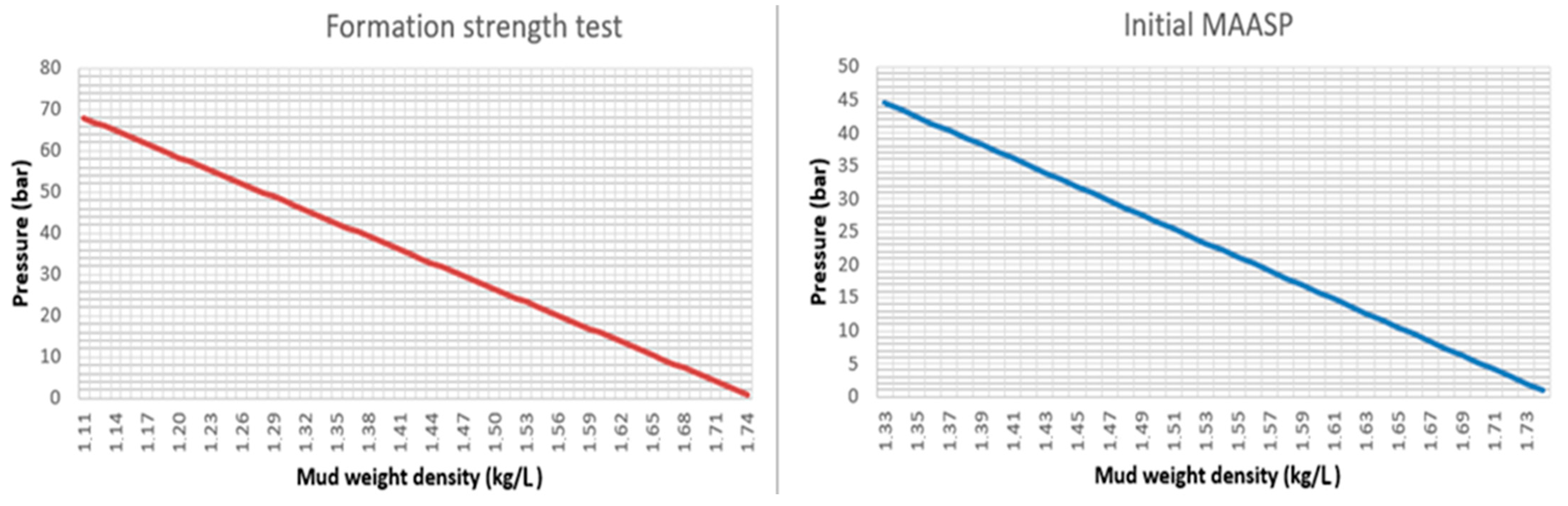
- Maximum Allowable Mud Weight
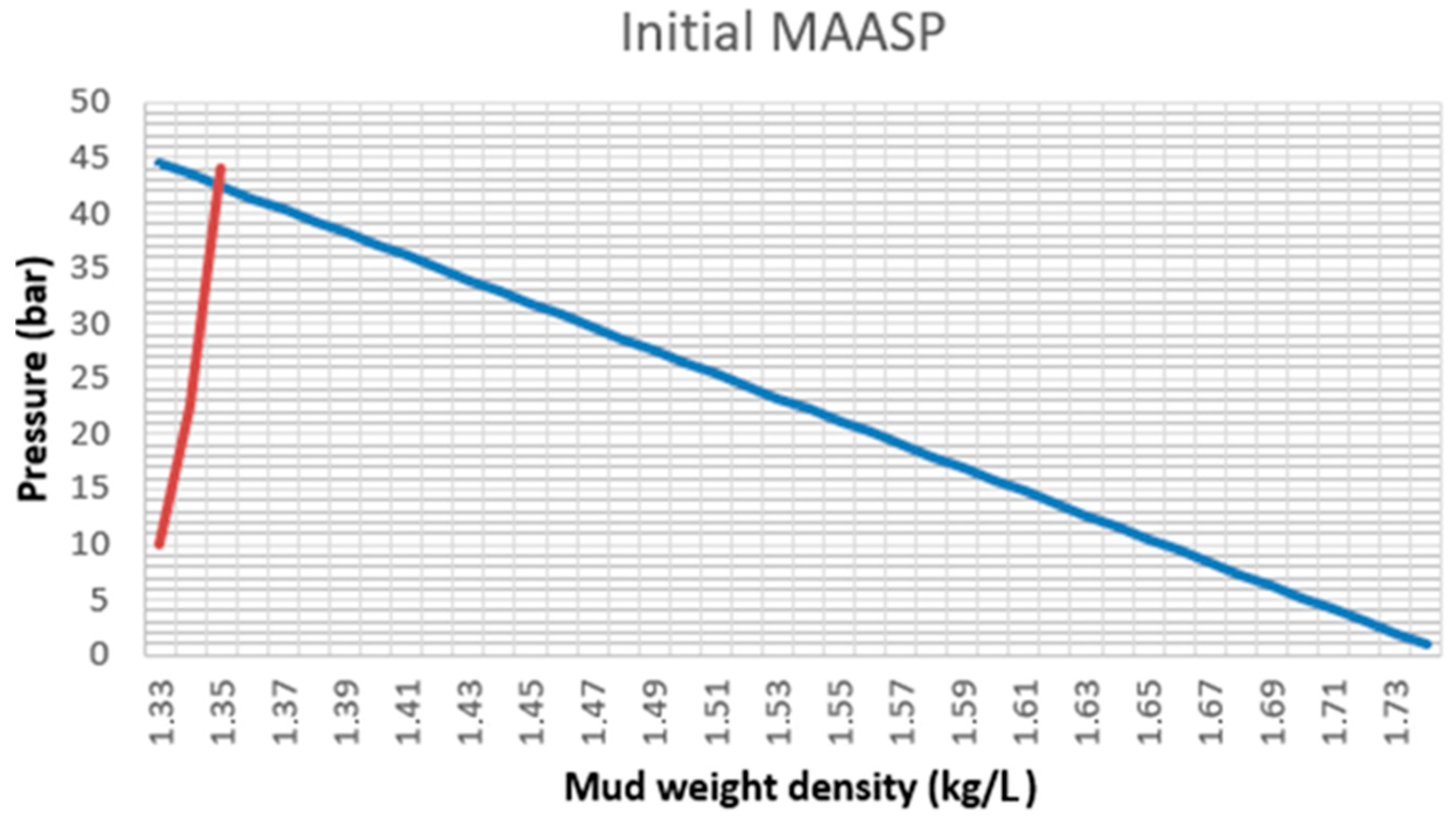
- Maximum Allowable Annulus Surface Pressure (MAASP)
- Assessment of Teoretic Fracturing Pressure
3. Results and Discussion
- Perform casing integrity test;
- Prepare a Leak-off test form;
- Drill out a casing shoe and drill 5 m of new hole;
- Circulate bottom up to condition mud and stabilize a mud density;
- Pull up into casing. Make sure that not pump a slug or LCM prior to the test;
- Rig up pumping unit, pump mud through test lines, and make a surface lines pressure tests;
- Close annular or pipe rams of BOP;
- Pump down the drill pipe at 40 or 80 L/min. Maintain the constant pump rate assigned;
- During the test, record and plot cumulative volume pumped vs. drill pipe pressure for every 40 L/m pumped, regardless of the pump rate;
- Permeability in the open hole may cause pressure build-up to be non-linear. If this occurs, stop the test, bleed pressure to zero, and retest at a pump rate that is 40 to 80 L/min higher than the previous test;
- Continue pumping until the predetermined maximum pressure is reached or until leak-off is confirmed;
- If pressure decreases, stop the pump immediately. Check surface lines and valves for leaks and make test again;
- If pressure levels off far below required pressure or leak-off, pump additional volume and check if a pressure increase;
- If performing a FIT test do not exceed maximum pressure required;
- When leak-off is confirmed, or maximum pressure is reached, stop pumping and close the shut-in valve;
- Observe and record shut-in pressure vs. time. Check surface lines and valves for leaks. If it is ok, continue, if not, perform a retest;
- Release pressure and record volume of fluid come back.
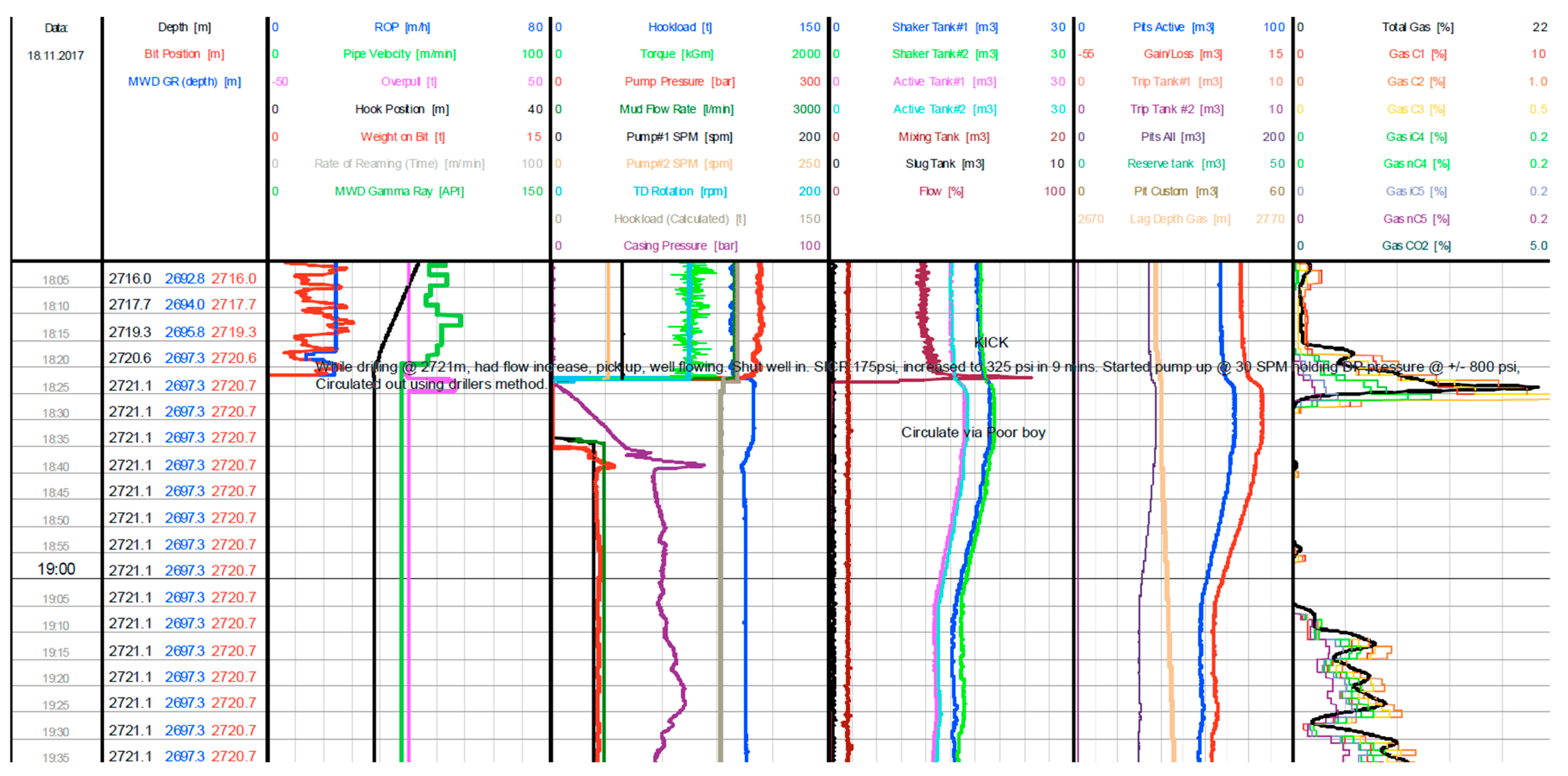
- The first option:
- -
- Use the drilling method to reduce the pressure on the bottom hole pressure and circulate the gas out. Assuming that the pressure will be constant, continue with the drilling method [22].
- The second option:
- -
- If the pressure is still increasing, use the Weight and Wait method and while a crew prepared a killing mud, we will release the pressure on the casing and hold a constant pressure on the SIDP [22].
- The third option:
- -
- Apply bullheading method [22].
- The fourth option:
4. Conclusions
Author Contributions
Funding
Institutional Review Board Statement
Informed Consent Statement
Data Availability Statement
Acknowledgments
Conflicts of Interest
Abbreviations
| API | American petroleum institute |
| BOP | Blow out preventer |
| ROP | Rate of penetration |
| WOB | Weight on bit |
| SIDP | Shut in drill pipe pressure |
| SICP | Shut in casing pressure |
| HCR | Hydraulic choke valve |
| OBM | Oil base mud |
| SIDPP | Shut in drill pipe pressure |
| SICP | Shut in casing pressure |
| LOT | Leak-off test |
| FIT | Formation integrity test |
| MAASP | Maximum allowable annular surface pressure |
| LCM | Lost circulation material |
| ICP | Initial Circling Pressure |
| FCP | Final Circling Pressure |
| W/W | Wait and Weight method |
| P/U | Pick up |
References
- Li, X.Z.; Hua, A.Z. Prediction and prevention of sandstone-gas outbursts in coal mines. Int. J. Rock Mech. Min. Sci. 2006, 43, 2–18. [Google Scholar] [CrossRef]
- Failler, P. Special Issue on Global Market for Crude Oil. Energies 2021, 14, 1199. [Google Scholar] [CrossRef]
- Pinka, J.; Wittenberger, G.; Engel, J. Borehole Mining, 1st ed.; FBERG TU: Kosice, Slovakia, 2007; p. 233. [Google Scholar]
- Jung, J.; Han, D.; Kwon, S. Well placement optimisation using a productivity potential area map. Int. J. Oil Gas Coal Technol. 2021, 27, 41–53. [Google Scholar] [CrossRef]
- Atashnezhad, A.; Wood, A.D.; Fereidounpour, A.; Khosravanian, R. Designing and optimizing deviated wellbore trajectories using novel particle swarm algorithms. J. Nat. Gas Sci. Eng. 2014, 21, 1184–1204. [Google Scholar] [CrossRef]
- Klempa, M.; Malis, J.; Sancer, J.; Slivka, V. Research of Stowing Material for Filling of Free Underground Spaces of Old Mine Works. Inz. Miner.-J. Pol. Miner. Eng. Soc. 2018, 2, 321–325. [Google Scholar] [CrossRef]
- Marbun, B.; Sinaga, S.; Purbantanu, B.; Ridwan, R. Improvement of Loads Calculation of the Perforated Liner in a Geothermal Production Well. Renew. Energy 2021, 174, 468–486. [Google Scholar] [CrossRef]
- Bildstein, J.; Strobel, J. Formation Pressure while Drilling, a valuable alternative in difficult drilling environment in Northern Germany. In Proceedings of the EAGE Annual Conference, Madrid, Spain, 13–16 June 2005. [Google Scholar] [CrossRef]
- Sun, S.H.; Yan, T.; Bi, X.L.; Wang, P. Analysis on the Influence Factors of Well Deviation in Gas Drilling. Adv. Mater. Res. 2012, 577, 132–136. [Google Scholar] [CrossRef]
- Feng, Y.; Gray, K.E. A Comparison Study of Extended Leak-Off Tests in Permeable and Impermeable Formations. In Proceedings of the ARMA US Rock Mechanics/Geomechanics Symposium, Houston, TX, USA, 26–29 June 2016. [Google Scholar]
- Chang, D.; Li, G.; Shen, Z.; Huang, Z.; Tian, S.; Shi, H.; Song, X. A Study on the Effect of Bottom-hole Differential Pressure on the Rock Stress Field. Energy Sources Part A Recovery Util. Environ. Eff. 2014, 36, 275–283. [Google Scholar] [CrossRef]
- Ni, H.; Wang, R.; Song, W.; Song, H. Study on the Mechanism of Bottom Hole Hydraulic Pulse Increasing Drilling Rate. Adv. Mater. Res. 2012, 354–355, 621–626. [Google Scholar] [CrossRef]
- Pindor, T. Innovative methods of natural gas exploitation as a factor of sustainable development of world economy. Ekon. i Srodowisko-Econ. Environ. 2017, 4, 205–217. [Google Scholar]
- Knez, D.; Rajaoalison, H. Discrepancy between measured dynamic poroelastic parameters and predicted values from Wyllie’s equation for water-saturated Istebna sandstone. Acta Geophys. 2021, 69, 673–680. [Google Scholar] [CrossRef]
- Malvić, T.; Barudžija, U.; Pašić, B.; Ivšinović, J. Small Unconventional Hydrocarbon Gas Reservoirs as Challenging Energy Sources, Case Study from Northern, Croatia. Energies 2021, 14, 3503. [Google Scholar] [CrossRef]
- Lavrov, A.; Larsen, I.; Bauer, A. Numerical Modelling of Extended Leak-Off Test with a Pre-Existing Fracture. Rock Mech. Rock Eng. 2016, 49, 1359–1368. [Google Scholar] [CrossRef]
- Volkov, M.; Björk, H.; Kudriavaia, N.; Andrews, J.S.; Carlsen, T.; Strøm, S. The Value of Integrated Downhole Passive Acoustic Monitoring During an Extended Leak Off Test to Prove Formation Integrity. In Proceedings of the SPE/IADC Drilling Conference and Exhibition, Virtual, 8–12 March 2021. [Google Scholar]
- Available online: https://www.drillingmanual.com/maasp-maximum-allowable-annular-surface-pressure/?utm_content=cmp-true (accessed on 24 April 2023).
- Abilov, E. Improving Formation Pressure Integrity Tests with Field-Wise Test Data Analysis and Hydraulic Impedance Testing. Ph.D. Thesis, King Abdullah University of Scientific and Technology, Thuwal, Saudi Arabia, 2021. [Google Scholar]
- Project: Drilling programm OGD Central Kft, Exploration well D-1, project, corporate material 2017.
- API RP 59 Recommended Practice for Well Control Operations, 2nd ed. 2006. Available online: https://global.ihs.com/doc_detail.cfm?document_name=API%20RP%2059&item_s_key=00125836 (accessed on 20 March 2023).
- Huszar, T.; Wittenberger, G.; Skvarekova, E. Warning Signs of High-Pressure Formations of Abnormal Contour Pressures When Drilling for Oil and Natural Gas. Processes 2022, 10, 1106. [Google Scholar] [CrossRef]
- Jameel, N.; Ali, J.A. Field and Experimental Investigations on the Effect of Reservoir Drill-In Fluids on Penetration Rate 538 and Drilling Cost in Horizontal Wells. Gels 2023, 9, 510. [Google Scholar] [CrossRef] [PubMed]
- Tahr, Z.; Jagar, A.A.; Ahmed, S.M. Sustainable aspects behind nano-biodegradable drilling fluids. Geoenergy Sci. Eng. 2023, 222, 211443. [Google Scholar] [CrossRef]


| Name | Depth (MD) | Depth (TVD) | Overpressure (%) | Pressure (MPa) | Pressure (Psi) | SG eqv. | Temperature (°C) |
|---|---|---|---|---|---|---|---|
| Holocene-Pleistocene | 0 | 0 | 0 | 10 | |||
| Top Upper Pannionan | 970 | 954.6 | 0 | 9.36 | 1357 | 1.00 | 65 |
| Top Újfalu | 1202 | 1185 | 0 | 11.62 | 1684 | 1.00 | 77 |
| Dynamo ULN 33 top | 1522 | 1505 | 0 | 14.76 | 2141 | 1.00 | 93 |
| Dynamo ULN 33 base | 1552 | 1535 | 0 | 15.06 | 2183 | 1.00 | 95 |
| Dynamo-Deep ULN 33 top | 1572 | 1555 | 0 | 15.25 | 2212 | 1.00 | 96 |
| Dynamo-Deep ULN 33 base | 1602 | 1585 | 0 | 15.55 | 2254 | 1.00 | 97 |
| Top Algyö | 1671 | 1600 | 0 | 15.75 | 2276 | 1.00 | 98 |
| Top Miocene | 2227 | 2210 | 15 | 24.93 | 3615 | 1.15 | 130 |
| TD | 2316 | 2299 | 15 | 25.94 | 3760 | 1.15 | 135 |
Disclaimer/Publisher’s Note: The statements, opinions and data contained in all publications are solely those of the individual author(s) and contributor(s) and not of MDPI and/or the editor(s). MDPI and/or the editor(s) disclaim responsibility for any injury to people or property resulting from any ideas, methods, instructions or products referred to in the content. |
© 2023 by the authors. Licensee MDPI, Basel, Switzerland. This article is an open access article distributed under the terms and conditions of the Creative Commons Attribution (CC BY) license (https://creativecommons.org/licenses/by/4.0/).
Share and Cite
Wittenberger, G.; Huszar, T.; Skvarekova, E.; Cambal, J.; Bugnova, M. Dependency of Pressure Expression towards Formation Pressures during Drilling Operations in Hydrocarbon Wells and Suitable Choice of Pressure Control Method. Processes 2023, 11, 3054. https://doi.org/10.3390/pr11113054
Wittenberger G, Huszar T, Skvarekova E, Cambal J, Bugnova M. Dependency of Pressure Expression towards Formation Pressures during Drilling Operations in Hydrocarbon Wells and Suitable Choice of Pressure Control Method. Processes. 2023; 11(11):3054. https://doi.org/10.3390/pr11113054
Chicago/Turabian StyleWittenberger, Gabriel, Tomas Huszar, Erika Skvarekova, Jozef Cambal, and Michaela Bugnova. 2023. "Dependency of Pressure Expression towards Formation Pressures during Drilling Operations in Hydrocarbon Wells and Suitable Choice of Pressure Control Method" Processes 11, no. 11: 3054. https://doi.org/10.3390/pr11113054