
Design and Testing of the Peanut Pod Cleaning Device
by
Chenhui Zhu
1, 
Bo Chen
1,
Jiongqi Li
1,
Yuan Liu
1,
Liquan Yang
2,
Wanzhang Wang
1 and
Hongmei Zhang
1,* 1
College of Mechanical and Electrical Engineering, Henan Agricultural University, Zhengzhou 450002, China
2
Henan Province Engineering Research Center of Ultrasonic Technology Application, Pingdingshan University, Pingdingshan 467000, China
*
Author to whom correspondence should be addressed.
Processes 2023, 11(1), 106; https://doi.org/10.3390/pr11010106
Submission received: 1 November 2022
/
Revised: 22 December 2022
/
Accepted: 26 December 2022
/
Published: 30 December 2022
(This article belongs to the Special Issue Method Optimization of Various Food Processing Technologies)
Abstract
:Due to the design of peanut harvesters and cleaners, peanut pods are often mixed with soil, gravel, peanut straw, and other impurities. To solve this problem, this study focused on designing a peanut pod cleaning device by integrating a negative pressure centrifugal fan, a hydrometric cleaning sieve, and a reversible long-mesh cleaning sieve. The relative motion of the peanut pod on the sieve was discussed, its stress analyzed, the design parameters of the sieve and fan determined, and the operation of the device was monitored by using sensors, which accurately recorded and adjusted the working parameters. Finally, the key parameters were tested, and the results showed that the design requirements were met at a vibration frequency of 5.5 Hz, a hydrometric cleaning sieve inclination of 15°, a reciprocating long mesh cleaning sieve inclination of 5°, and a fan speed of 1500 rev/min; the mean loss is 2.26%, and the mean impurity is 3.18%. The findings can be used to provide technical support and reference for the development of peanut pod cleaning devices.
1. Introduction
Peanut is an important oil crop and protein resource [1,2,3] widely planted in many countries and regions [4,5]. In China, the planting area of peanuts is large. In most areas, peanut harvesting requires a lot of manpower and material resources, which is inefficient and costly. Foreign peanut harvesters are technologically advanced and mature but unsuitable for China due to high prices and different planting modes [6,7]. China used to have small machines for peanut harvesting, which has a lower mechanization level than other countries. However, technological advances in large- and medium-sized peanut harvesters have been made. Peanut combine harvesters of four, six, and eight rows have been used in a few areas, including Xinjiang and northeast China, promoting the development of peanut harvesting technology to a certain extent [8,9].
Peanut pod cleaning is an important link in the process of flower vitality harvesting [10,11,12], where impurities are separated at the site to facilitate the transportation and preservation of peanut pods [13,14]. The materials transported to the cleaning device contain peanut pods, broken stems, residual stems and leaves, soil, and gravel, which must be sieved and cleaned [15]. As the working environment in the field is complex and changeable, the composition, length, and moisture content of the materials vary, which often causes problems, for example, poor separation of peanut pod impurities [16,17,18]. In previous studies on peanut and other seed cleaning devices, many types of cleaning devices with different construction designs were used [19,20,21,22]. Previous research on the screening characteristics of materials and the modeling of screening devices [23,24] provides a theoretical basis for the screening and cleaning of materials [25]. However, In China, it is not enough to only look at the impact of cleaning rate, vibration noise, and instability on the cleaning effect [26,27,28,29]. Peanut pod cleaning devices should be easily transported with high efficiency. Small size and great cleaning effect are the key factors to be considered in the design. Therefore, it is critical to develop peanut pod cleaning devices that promise rapid transfer, convenient operation, optimal structure and parameters, and reduced impurity and losses.
This research focused on designing a peanut pod cleaning device capable of flexible operation in the field based on theoretical analysis and a field test. The test determined the device’s key structure and working parameters, and the results can serve as a research basis for the development of peanut pod cleaning devices.
2. Design and Working Principle
2.1. Design of the Peanut Pod Cleaning Device
Based on the material characteristics and composition, a peanut pod cleaning device was designed, as shown in Figure 1, on the principles of easy transfer, low cost, and ease of operation. It is composed of a collecting bin, a reciprocating long mesh cleaning sieve, a front rotary elevator, a walking chassis, a hydrometric cleaning sieve, a rear rotary elevator, a cleaning bin, a negative pressure cleaning fan, and an electronic information acquisition system, etc., which can facilitate structure parameter optimization and working parameter acquisition.
When the peanut pod cleaning device is in operation, the peanut pods containing impurities are first collected in the collecting bin, and the outlet in the lower part of the bin causes the peanut pods to fall into the reciprocating long-mesh cleaning sieve, as shown in Figure 1. The inclined long meshes at the bottom of the reciprocating long-mesh cleaning sieve sift out soil and gravel with a diameter of less than 5 mm during the vibration and sliding of the peanut pods. Once sieved, the peanut pods are transported upward by a circular rotary elevator and an inclined hopper, where they naturally fall into the hydrometric cleaning sieve, whose high-frequency vibration shakes large stones and soil out of the sieve. The air inlet of the negative pressure fan is located above the hydrometric cleaning sieve. High negative pressure is created in the sieve cavity by the action of the high-speed centrifugal fan. The airflow draws light impurities from the bottom of the hydrometric cleaning sieve into the upper air inlet. Meanwhile, the meshes at the bottom of the hydrometric cleaning sieve have the same effect as those of the reciprocating long-mesh cleaning sieve, which sieves out small-size impurities and completes the second cleaning of the peanut pods. The peanut pods slide onto the lower rear exit of the constantly shaking inclined sieve, then into the secondary rotary elevator, and eventually into the clean material bin. The cleaned peanut pods are brought into the granary by the secondary rotary elevator and can be bagged or loaded through the feed outlet below. The process is shown in Figure 2.
2.2. Design of the Electronic Information Acquisition System
The electronic information acquisition system primarily consists of the OMRON E6B2-CWZ6C encoder and the CHENGKE CT1010L vibration sensor. The former is installed on the fan shaft and the drive cleaning sieve shaft, and the latter on the vibration sieve. The system accurately records the frequency of the measurements and provides feedback on the speed of the closed-loop control motor.
3. Components Design and Parameters Determination
3.1. Design of the Crank-Rocker Cleaning Sieve
As shown in Figure 3, the cleaning sieve consists of a reciprocating long-mesh cleaning sieve HKR and a hydrometric cleaning sieve BCED; the two sieves are connected by a link, RC, at both ends. OA is the eccentric bearing of the driving link, which rotates around point O of the transmission shaft axis and drives the reciprocating vibration of BCED through link AB. Similarly, BCED drives the reciprocating vibration of HKR through link RC.
The freedom degree of this mechanism was calculated as follows: the number of the moving links was 9 (n = 9), i.e., O4H, HKR, O3K, RC, OA, AB, BCED, DO1, and EO2; the number of kinematic pairs was 13, (PL = 13), including O3, O4, H, K, R, C, B, E, D, A, O, O1, and O2, all of which were the revolute pairs; and there was no higher pair, so PH = 0.
The equation for the freedom degree is:
When the number of the freedom degree was 1 (F = 1), and the number of the driving links was also 1, the design requirements were met for specific motion.
In order to speed up the screen surface and reduce the power losses of the mechanism in operation, the bottom surface of the screening screen should incline with linear vibration. Therefore, the components of this mechanism should meet requirements such as: O4H parallel and equal to O3K, O2E parallel and equal to O1D, and OA << AB. When designing this mechanism, OA = 8.5 mm, AB = 328.5 mm, BD = 645 mm, O1D = 291 mm, BC = 65 mm, RC = 1150 mm, CE = 612 mm, ED = 1312 mm, RH = 1353 mm, RK = 168 mm, HK = 1270 mm, and O3K = 291 mm.
3.2. Determination of the Inclination and Vibration Frequency Parameters of the Hydrometric Cleaning Sieve
Size cleaning is used in the reciprocating long-mesh cleaning sieve. The long meshes of 5 mm × 50 mm at the bottom remove soil and gravel with diameters less than 5 mm and other impurities. The hydrometric cleaning sieve also removes small-size impurities through the meshes at the bottom: light impurities through the upper fan and heavy impurities through a set frequency of vibration. Hence, the material motion and structure parameters of the hydrometric cleaning sieve. The relative motion of the peanut pod on the sieve M1 at the centroid of the hydrometric cleaning sieve bottom was analyzed by using the dynamic method, and the hydrometric cleaning sieve was approximated as straight line motion. The peanut pod slides downward, upward, or jumps on the sieve. Figure 3 shows that the stress of M1 sliding downward is relative to the sieve bottom. Based on extensive test verification [30,31], α was 15°. As the hydrometric cleaning sieve was approximated as straight line motion in a direction perpendicular to link O1D, it was measured in the design drawing that α was about 18° and μ was approximately 75°.
When M1 slides downward relative to the sieve bottom, it meets:
If M1 does not jump from the sieve bottom, then:
The friction force of the sieve bottom against M1 is:
The gravity of M1 is:
where F1 is the friction force of the sieve bottom against M1, N; P1 is the D’Alembert inertial force of M1, N; G1 is the gravity of M1, N; Q1 is the acting force of the negative pressure fan along the direction of the suction airflow against M1, N; N1 is the normal force of the sieve bottom against M1, N; δ is the angle between the point D along the velocity direction and the sieve bottom, (°); α is the sieve inclination, (°); μ is the angle between the negative pressure fan along the direction of the suction airflow and the ground, (°); m is the quality of M1, kg; g is the acceleration of gravity, m/s2; φ is the angle between the sieve bottom and the static friction force of M1, which was usually 35°in tests. By combining Equations (2)–(5), the following equation is obtained:
The D’ Alembert inertial force of M1 is:
The acting force [32] of the negative pressure fan along the direction of the suction airflow against M1 is:
where ω is the angular frequency of the sieve bottom, rad/s; λ is the vibration amplitude of the sieve bottom, m; t is the motion time, s; v is the speed of the negative pressure air, whose value is less than the minimum suspension speed of M1, that is, 8 m/s [33]; kp is the floating coefficient of M1, which is 0.085 m−1 by reference. Substituting Equations (7) and (8) into Equation (6), the condition of M1 sliding down relative to the sieve bottom is obtained when the sinωt takes the maximum value, namely 1:
Likewise, the condition of M1 sliding upward relative to the sieve bottom is obtained:
If M1 jumps vertically from the sieve bottom, then N1 < 0, as shown in Figure 3. After all the parameters were substituted into the above equation, and N1 > 0 were obtained. At this time, M1 will not jump from the sieve bottom. When F1 and P1 were opposite of those in Figure 3, the following equation was obtained:
Substituting Equations (7) and (8) into Equation (11), when the sinωt takes the maximum value, namely 1, the condition of M1 jumping from the sieve bottom was obtained:
To achieve the best sieving effect, M1 should slide upward and downward relative to the sieve bottom, and the distance sliding downward should be greater than that upward (KX > KS). In addition, the jump of M1 from the sieve bottom should be conducive to dispersion and uniformity, sieving out impurities to the greatest extent. Thus, the λω2 in the above equation shall meet the condition when M1 is sliding downward, upward, and jumping from the sieve bottom, namely: λω2 > KX > KS and λω2 > KT. Therefore, the vibration acceleration of the sieve bottom at M1 is obtained when aM = λω2 > 14.21 m/s2. The sieving efficiency is proportional to the vibration acceleration, and too large a vibration acceleration will lead to too fast a motion of the peanut pod on the sieve bottom. As a result, the peanut pod will escape from the sieve, weakening the sieving capacity. Therefore, the vibration acceleration aM is better within 2.5 times the gravity acceleration and meets the following condition:
As the sieve was approximated as straight line motion, the vibration amplitude at any part of the sieve is the same, including point D. According to this design drawing, the vibration amplitude of the sieve bottom is 16 mm, λ ≈ 16 mm. By substituting λ into Equation (13), the angular frequency range of the sieve bottom, namely 29.8 rad/s < ω < 39.13 rad/s, was obtained, as the vibration of the sieve is driven by the crank OB, and the angular frequency ω of the sieve bottom is the same as the angular speed ωOB of the crank OB. Therefore, the speed limit range nOB of the crank OA was 284.7 rev/min < nOB < 373.85 rev/min.
4. Field Test
4.1. Test Situation
The prototype was tested in a field in Huatugula Town, Tongliao City, Inner Mongolia Autonomous Region, in October 2021. The peanut variety tested was “Huayu 23”, planted in single ridge and double-row, at a distance of 850 mm, with 150,000–165,000 peanuts per ha. The average yield of peanut pod and peanut kernel was 4222.5 kg and 3175.5 kg per ha, respectively. The cleaning device is shown in Figure 4. After the peanut harvester dumped the material into the collecting bin of the prototype, the control board at the bottom of the collecting bin adjusted the feeding speed to 3 tons per hour.
In the theoretical analysis and preliminary tests, the test parameters used include the vibration frequency λ, the sieve inclination α, and the fan speed n of the hydrometric cleaning sieve. The structure parameters of the test fan are shown in Table 1.
The three-factor and the three-level orthogonal test was conducted with two technical indicators, i.e., the losses R1 and impurities R2, and the results are shown in Table 2. The value ranges of the vibration frequency and the main fan speed were determined by previous analysis values. During the test, the vibration frequency was changed by adjusting the output speed of the tractor engine, the sieve inclination by adjusting the height of the support seat of the working chassis, and the fan speed by replacing the fan pulley of different diameters.
4.2. Test Methods and Indicators
In line with the Standard for Machinery Industry of the PRC JB/T13076-2017, each of the three-factor and the three-level orthogonal combinations [34,35] was repeated five times to test the losses and impurities, and the values were averaged. The collecting bin, the material bin, the sieve surface, and the rotary elevator must be cleaned for each test, as well as a clean canvas tarpaulin placed below the machine for collecting ground materials. Meanwhile, a breathable bag was required at the outlet of the fan air. Testing once for each unloading of 200 kg of materials in the collecting bin, the losses mass was the sum of the peanut pods in the canvas tarpaulin and the outlet of the fan air. The impurity mass was calculated by the sampling of 50 ± 5 kg in the clean canvas tarpaulin, where the peanut pods were separated from impurities and weighed manually. Losses include damages to pods and loss of peanuts from pods. The losses and the impurities were calculated based on Equations (15) and (16).
where PS is the total loss, %; MS is the total loss mass of the peanut pods, g; PZ is the impurity, %; MZ is the mass of the peanut pods in the clean material bin, g; MH is the mass of impurities in the clean material bin, g.
The orthogonal test results are shown in Table 3. By referencing the Design-Expert software, the mathematical model of the losses and impurities were obtained respectively:
where A is Vibration frequency, Hz; B is Sieve inclination angle; C is Fan speed, rev/min−1.
4.3. Analysis of the Losses
The fitness and analysis of the mathematical model R1 showed that P was 0.0012, less than 0.05, indicating significance in the losses. Except for the quadratic term of the vibration frequency, other factors had a significant but varied effect on the losses: vibration frequency > fan speed > sieve inclination. The response surface curves for the effects of the interaction terms against the losses are shown in Figure 5.
There were similar interaction term effects of the losses between the vibration frequency and the sieve inclination and the vibration frequency and the fan speed. As shown in Figure 5a, when the sieve inclination was constant, the losses increased with the increase of the vibration frequency at a fan speed of 1300 rev/min. The losses decreased with the increase of the sieve inclination when the vibration frequency was low and increased with the increase of the sieve inclination when the vibration frequency was high. In Figure 5b, when the fan speed was constant, the losses increased with the increase of the vibration frequency at the sieve inclination of 15°. The losses increased with the increase of the fan speed when the vibration frequency was low, and they first decreased and then increased with the increase of the fan speed when the vibration frequency was high. In Figure 5c, when test factors were at a low level, the losses were increased at a vibration frequency of 5.5 Hz, and they first decreased and then increased when the test factors were at a high level.
4.4. Analysis of the Impurities Test Results
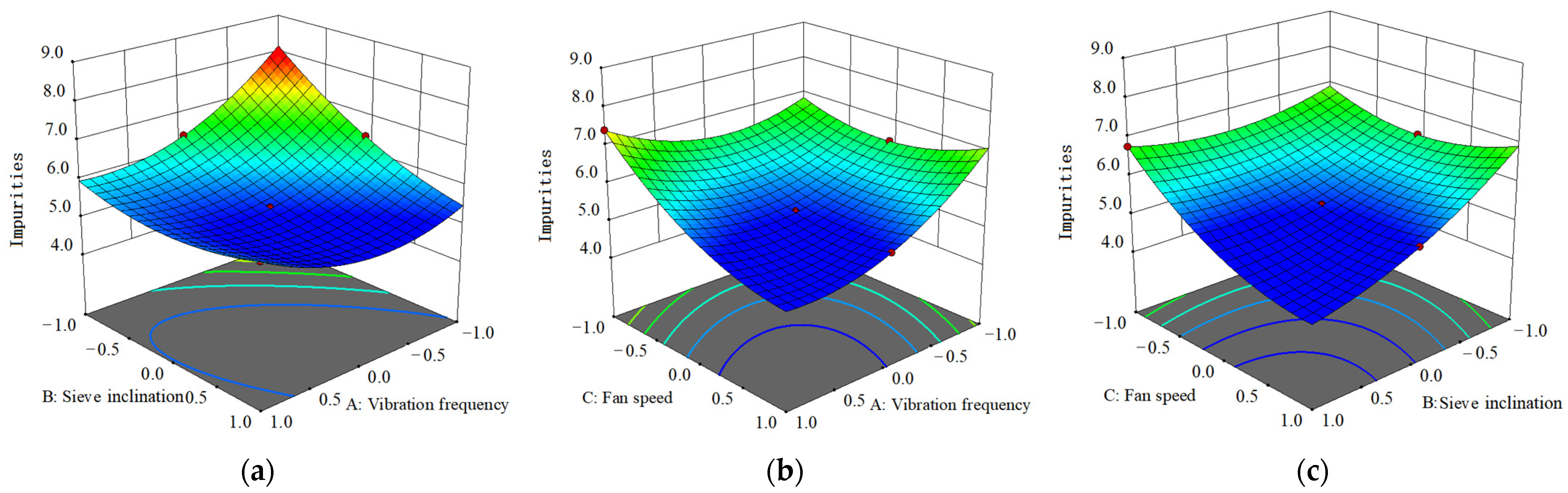
The fitness and analysis of the mathematical model R1 showed that P was 0.0009, less than 0.05, indicating significance in the losses. All factors’ interaction terms and quadratic terms had a significant but varied effect on the impurities: sieve inclination > fan speed > vibration frequency. The response surface curves for the effects of the interaction terms against the impurities are shown in Figure 6.
As can be seen in Figure 6a, when the vibration frequency was low, the impurities decreased with the increase of the sieve inclination at a fan speed of 1300 rev/min; when the vibration frequency was high, the impurities first decreased and then rebounded with the increase of the sieve inclination. In Figure 6b, when the vibration frequency was constant, the impurities decreased with the increase of the fan speed at a sieve inclination of 15°. Moreover, impurities increased with the increase of the vibration frequency when the fan speed was low and decreased with the increase of the vibration frequency when the fan speed was high. In Figure 6c, when the sieve inclination was constant, the impurities decreased with the increase of the fan speed at a vibration frequency of 5.5 Hz and decreased with the increase of the sieve inclination.
4.5. Parameter Optimization and Test Verification
The working parameters of the peanut pod cleaning device were optimized by referencing the Design-Expert software, and the mathematical model of the optimization process is as follows:
As shown above, the optimum working parameters are obtained at a vibration frequency of 5.5 Hz, sieve inclination of 15°, and fan speed of 1500 rev/min, with losses of 2.51% and impurities of 5.29%. The damage and loss of peanuts from pods were relatively low, reflected in the squeezing of pods and the damage of single-side pods, which may be caused by the collision between pods and rocks when the vibration frequency was relatively high. The field test using the peanut pod cleaning device was repeated five times to verify the results, and the design requirements were well met at a vibration frequency of 5.5 Hz, sieve inclination of 15°, and fan speed of 1500 rev/min, with mean losses of 2.26% and mean impurities of 3.18%.The validation test results are shown in Table 4.
5. Discussion
In this paper, a double-screen cleaning device was designed to separate peanut pods from impurities in the field, and a great cleaning effect was achieved. At the same time, a rotary elevator was used to lift peanut pods, which reduced the overall size of the cleaning device and facilitated field transportation by the tractor. The above two points meet the design requirements of the cleaning device. On the basis of the theoretical analysis of key components, three factors, namely vibration frequency, fan speed, and sieve inclination with a great impact on the cleaning performance, were selected for the orthogonal test. Although the double-screen cleaning device can effectively avoid hanging seedlings by wrapping film and blocking the screen surface, there are still some problems. Due to technical limitations, the influence of peanut varieties and peanut moisture content on the cleaning and damage has not been investigated in this test. During the test, it was found that the lateral inclination of the cleaning device caused by terrain fluctuation led to an increased collection of materials on one side of the screen surface, thus reducing the cleaning quality. The cleaning device is in need of a leveling mechanism because each plot might not have a relatively flat site. The next step is to adjust the three parameters of vibration frequency, screen surface inclination, and fan speed under different water content and soil conditions to achieve a better cleaning effect.
6. Conclusions
- (1)
- The peanut pod cleaning device designed in the research is composed of a collecting bin, a reciprocating long mesh cleaning sieve, a front rotary elevator, a walking chassis, a hydrometric cleaning sieve, a rear rotary elevator, a clean material bin, and a negative pressure cleaning fan, etc. Through calculation, the optimized structural parameters of the cleaning device were obtained, which can effectively solve the problems of poor separation of impurities, high losses, film wrapping, seedling hanging, and screen surface blockage, etc., under the working conditions of a high feed rate and efficient harvest.
- (2)
- By investigating the impact of the vibration frequency, the sieve inclination, and the fan speed on the losses and impurities, the optimum working parameters were obtained in the orthogonal test. The test results showed that the design requirements were met at a vibration frequency of 5.5 Hz, hydrometric cleaning sieve inclination of 15°, reciprocating long mesh cleaning sieve inclination of 5°, and fan speed of 1500 rev/min, with mean losses of 2.26%, and mean impurity of 3.18%.
- (3)
- The test results also showed that the double-screen structure was feasible with a good cleaning effect. The rotary elevator makes the device more compact and suitable for peanut pod field cleaning. In order to achieve better cleaning effects, the three parameters of the machine, i.e., vibration frequency, screen surface inclination, and fan speed, have to be automatically regulated under different water content and soil conditions.
Author Contributions
Conceptualization, C.Z. and W.W.; methodology, C.Z.; software, C.Z.; validation, J.L., L.Y. and B.C.; formal analysis, Y.L. and B.C.; investigation, C.Z.; resources, C.Z. and W.W.; data curation, C.Z. and Y.L.; writing—original draft preparation, C.Z.; writing—review and editing, C.Z.; visualization, H.Z.; supervision, H.Z.; project administration, W.W.; funding acquisition, H.Z. All authors have read and agreed to the published version of the manuscript.
Funding
This research was funded by the Major Public Research Projects in Henan Province (201300110400); the Henan Province Science and Technology Research (222102110457); and the Key Scientific Research Projects of Henan Province colleges and universities (20A210029).
Institutional Review Board Statement
Not applicable.
Informed Consent Statement
Not applicable.
Data Availability Statement
The data used to support the findings of this study are available from the corresponding author upon request.
Conflicts of Interest
The authors declare no conflict of interest.
References
- Foreign Agricultural Service. World Agricultural Production; United States Department of Agriculture: Washington, WA, USA, 2020.
- National Agricultural Statistics Service. Crop Production; United States Department of Agriculture: Washington, WA, USA, 2019.
- Foreign Agricultural Service. Oileseeds: World Markets and Trade—Feb 2019; United States Department of Agriculture: Washington, WA, USA, 2019.
- Liu, J.; Tang, F.S.; Zhang, J.; Zang, X.W.; Dong, W.Z.; Yi, M.L.; Hao, X. Current status and development trends of peanut production technology in China. Chin. Agric. Sci. Bull. 2017, 33, 13–18. [Google Scholar]
- Lv, X.L.; Wang, H.; Zhang, H.J.; Hu, Z.C. Research and situation on peanut machinery harvesting in China. J. Agric. Mech. Res. 2012, 34, 245–248. [Google Scholar]
- Wang, D.W.; Shang, S.Q.; Han, K. Design and test of 4HJL-2 harvester for peanut picking-up and fruit-picking. Trans. Chin. Soc. Agric. Eng. 2013, 29, 27–36. [Google Scholar]
- Chen, Y.Q.; Wang, H.; Hu, Z.C. Research and analysis on harvest losses causes and control strategies of half-feeding peanut combine harvester. Chin. Agric. Mech. 2011, 33, 72–77. [Google Scholar]
- Chen, Z.Y.; Gao, L.X.; Charles, C. Analysis on technology status and development of peanut harvest mechanization of China and the united states. Trans. Chin. Soc. Agric. Mach. 2017, 48, 1–21. [Google Scholar]
- Gao, L.X.; Chen, Z.Y.; Charles, C. Development course of peanut harvest mechanization technology of the United States and enlightenment to China. Trans. Chin. Soc. Agric. Eng. 2017, 33, 1–9. [Google Scholar]
- Tang, B.; Lu, Z.M.; Guo, J.; Wang, Y.Q. Experimental investigation on cleaning device of peanut combine harvester. J. Agric. Mech. Res. 2016, 38, 191–195. [Google Scholar]
- Liu, C.Y.; Wang, S.S.; Shi, Q.X.; Geng, L.X.; Yang, F. Design of peanut combine harvester cleaning system test bench. J. Agric. Mech. Res. 2018, 40, 91–95. [Google Scholar]
- Gao, L.X.; Li, X.Q.; Guan, M.; Cheng, J.; Zhang, X.D.; Liu, Z.X. Design and test on cleaning device of peanut pods with double air-suction inlets with vibration screen. Trans. Chin. Soc. Agric. Mach. 2015, 46, 110–117. [Google Scholar]
- Yu, Z.Y.; Hu, Z.C.; Cao, M.Z.; Wang, S.Y.; Zhang, P.; Peng, B.L. Design of cleaning device of tangential flow and whole-feed peanut combine harvester. Trans. Chin. Soc. Agric. Eng. 2019, 35, 29–37. [Google Scholar]
- Sun, T.Z.; Shang, S.Q.; Li, G.Y. Design of stripping and cleaning system of 4HQL-2 type full- feed peanut combine. J. Agric. Mech. Res. 2009, 31, 54–57. [Google Scholar]
- El-Sayed, A.S.; Abdel-Hadi, M.A.; El-Amir, M.S.; El-Manawy, A.I. A study on separation and cleaning of peanut seeds. Misr J. Agric. Eng. 2017, 34, 35–52. [Google Scholar] [CrossRef]
- Li, Y.M.; Zhao, Z.; Chen, J.; Xu, L.Z. Nonlinear motion law of material on air-and-screen cleaning mechanism. Trans. CSAE 2007, 23, 142–147. [Google Scholar]
- Wang, D.W.; Wang, Y.Y.; Shang, J.Q.; Sun, Q.W. Research and analysis of large-scale peanuts picking-up and fruit picking harvest machine. Collect. Pap. CSAE 2011, 90–95. [Google Scholar]
- Liu, S.; Hu, C.; Wang, D.; Shang, S. Simulation and analysis of airflow field in peanut harvester based on FLUENT. J. Agric. Mech. Res. 2013, 35, 60–64. [Google Scholar]
- Stoleru, V.; Munteanu, N.; Istrate, A. Perception Towards Organic vs. Conv. Prod. Romania. Sustain. 2019, 11, 2394. [Google Scholar] [CrossRef] [Green Version]
- Panasiewicz, M.; Sobczak, P.; Mazur, J.; Zawislak, K.; Andrejko, D. The technique and analysis of the process of separation and cleaning grain materials. J. Food Eng. 2012, 109, 603–608. [Google Scholar] [CrossRef]
- Krzysiak, Z.; Samociuk, W.; Skic, A.; Bartnik, G.; Zarajczyk, J.; Szmigielski, M.; Dziki, D.; Wierzbicki, S.; Krzywonos, L. Effect of Sieve Drum Inclination Angle on Wheat Grain Cleaning in a Novel Rotary Cleaning Device. Trans. ASABE 2017, 60, 1751–1758. [Google Scholar] [CrossRef]
- Yang, H.; Yan, J.; Wei, H.; Wu, H.; Wang, S.; Ji, L.; Xu, X.; Xie, H. Gradient Cleaning Method of Potato Based on Multi-Step Operation of Dry-Cleaning and Wet Cleaning. Agriculture 2021, 11, 1139. [Google Scholar] [CrossRef]
- Ildar, B.; Salavat, M.; Ramil, L.; Valery, P.; Permyakov, R.I.; Ruslan, N. Mathematical modeling and research of the work of the grain combine harvester cleaning system. Comput. Electron. Agric. 2019, 165, 104966. [Google Scholar]
- Yuichi, Y.; Satoshi, I.; Atsuko, S.; Yoshiyuki, S.; Jusuke, H. Estimation equation for sieving rate based on the model for undersized particles passing through vibrated particle bed. J. Chem. Eng. Jpn 2013, 46, 116–126. [Google Scholar]
- Hennig, M.; Teipel, U. Grade efficiency for sieve classification processes. Can. J. Chem. Eng. 2017, 96, 259–264. [Google Scholar] [CrossRef]
- Krzysiak, Z.; Samociuk, W.; Zarajczyk, J.; Kaliniewicz, Z.; Pieniak, D.; Bogucki, M. Analysis of the Sieve Unit Inclination Angle in the Cleaning Process of Oat Grain in a Rotary Cleaning Device. Processes 2020, 8, 346. [Google Scholar] [CrossRef] [Green Version]
- Chai, X.; Xu, L.; Li, Y.; Qiu, J.; Li, Y.; Lv, L.; Zhu, Y. Development and Experimental Analysis of a Fuzzy Grey Control System on Rapeseed Cleaning Loss. Electronics 2020, 9, 1764. [Google Scholar] [CrossRef]
- Mangwandi, C.; Cheong, Y.S.; Adams, M.J.; Hounslow, M.J.; Salman, A.D. The coefficient of restitution of different representative types of granules. Chem. Eng. Sci. 2007, 62, 437–450. [Google Scholar] [CrossRef]
- Gao, X.; Xie, H.; Gu, F.; Wei, H.; Liu, M.; Yan, J.; Hu, Z. Optimization and experiment of key components in pneumatic peanut pod conveyor. Int. J. Agric. Biol. Eng. 2020, 13, 100–107. [Google Scholar] [CrossRef]
- China Academy of Agricultural Mechanization Sciences. Agricultural Machinery Design Manual; China Agricultural Science and Technology Press: Beijing, China, 2007; Volume II. [Google Scholar]
- Li, Y.M.; Wang, Z.H.; Xu, L.Z. Motion analysis and experimental research of rape extractions on vibration sieve. Trans. Chin. Soc. Agric. Eng. 2007, 23, 111–114. [Google Scholar]
- Gao, L.X.; Zhang, W.; Du, X.; Liu, X.; Yang, J.; Liu, M.G. Experiment on aerodynamic characteristics of threshed mixtures of peanut shelling machine. Trans. Chin. Soc. Agric. Eng. 2012, 28, 289–292. [Google Scholar]
- Chen, C.Y.; Wang, Z.H.; Li, Q.L. Mechanophysical properties of rape extractive and parametrical optimization of vibration sieve. Trans. Chin. Soc. Agric. Mach. 2005, 36, 60–63+70. [Google Scholar]
- Cheng, X.G.; Zhong, L.M. Design and test on belt-type seed delivery of air-suction metering device. Trans. Chin. Soc. Agric. Eng. 2012, 28, 8–15. [Google Scholar]
- Zhang, G.Z.; Luo, X.W.; Zang, Y. Experiment of sucking precision of sucking plate with group holes on rice pneumatic metering device. Trans. Chin. Soc. Agric. Eng. 2013, 29, 13–20. [Google Scholar]
Figure 1.
Diagram of the peanut pod cleaning device. 1. The collecting bin. 2. The front rotary elevator. 3. The negative pressure cleaning fan. 4. The clean material bin. 5. The rear rotary elevator. 6. The hydrometric cleaning sieve. 7. The reciprocating long mesh cleaning sieve.
Figure 1.
Diagram of the peanut pod cleaning device. 1. The collecting bin. 2. The front rotary elevator. 3. The negative pressure cleaning fan. 4. The clean material bin. 5. The rear rotary elevator. 6. The hydrometric cleaning sieve. 7. The reciprocating long mesh cleaning sieve.
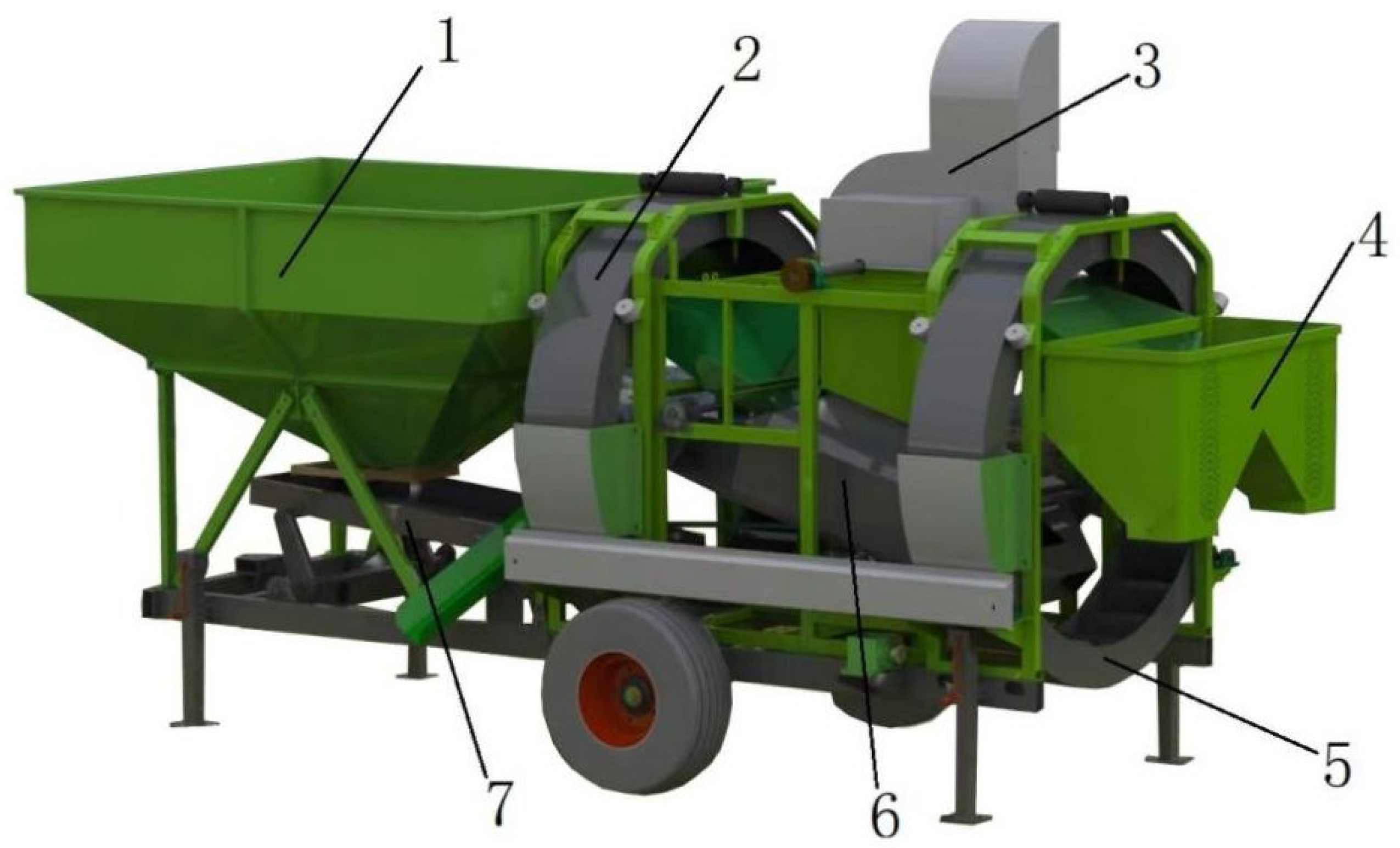
Figure 2.
The process diagram of the peanut pod cleaning device (a,b).
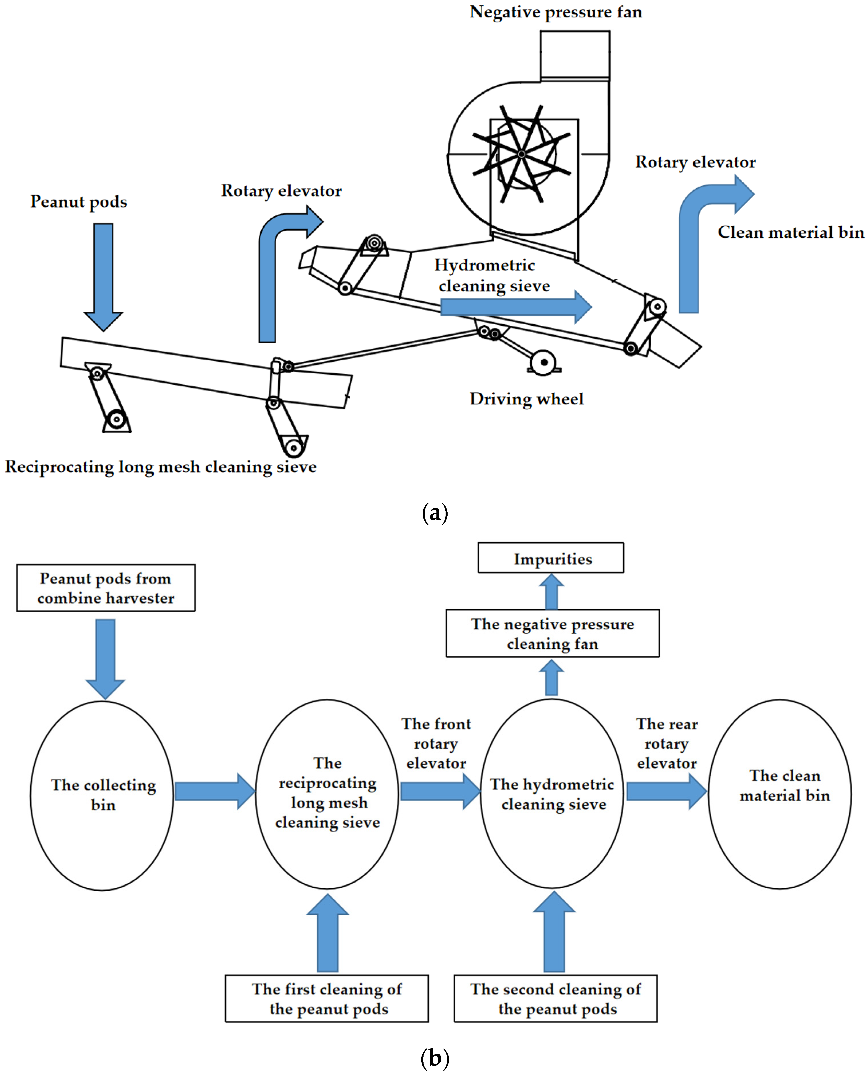
Figure 3.
The motion of the cleaning mechanism and the material force analysis. Note: OA: crank of the driving link; O: transmission shaft axis; HKR: reciprocating long mesh cleaning sieve; BCED: hydrometric cleaning sieve; O1–O4: hinge point of the frame; H, K, R, A–E: hinge points; M1, M2: peanut pod at the sieve bottom centroid; G: gravity of the peanut pod, (N); P1, P2: D’Alembert inertial force of the peanut pod, (N); F1, F2: friction force of the sieve bottom against the peanut pod, (N); Q1: acting force of the negative pressure fan along the suction airflow direction against the peanut pod, (N); N1, N2: normal force of the sieve bottom against the peanut pod, (N); α, θ: sieve inclination, (°); δ, γ: angle between the point D along the velocity direction and the sieve bottom, (°); μ: angle between the negative pressure fan along the suction airflow direction and the ground, (°).

Figure 4.
The physical photograph of cleaning device.

Figure 5.
Response surface curves for the effects of the interaction terms against the losses. (a) Sieve inclination and vibration frequency response surface curve. (b) Fan and vibration frequency response surface curve. (c) Fan and sieve inclination response surface curve.
Figure 5.
Response surface curves for the effects of the interaction terms against the losses. (a) Sieve inclination and vibration frequency response surface curve. (b) Fan and vibration frequency response surface curve. (c) Fan and sieve inclination response surface curve.
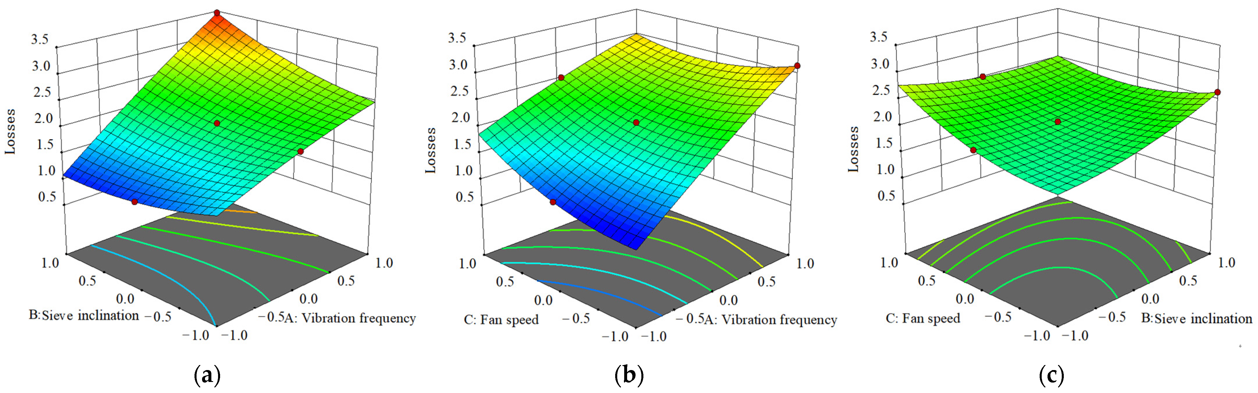
Figure 6.
Response surface curves for the effects of the interaction terms against the impurities. (a) Sieve inclination and vibration frequency response surface curve. (b) Fan and vibration frequency response surface curve. (c) Fan and sieve inclination response surface curve.
Figure 6.
Response surface curves for the effects of the interaction terms against the impurities. (a) Sieve inclination and vibration frequency response surface curve. (b) Fan and vibration frequency response surface curve. (c) Fan and sieve inclination response surface curve.

Table 1.
Structure parameters of the test fan.
| Structural Form | Impeller Diameter D/mm | Impeller Width B/mm |
|---|---|---|
| Negative pressure centrifugal fan | 770 | 230 |
Table 2.
Test factors and levels.
| Level | Vibration Frequency A/Hz | Sieve Surface Inclination B/° | Fan Speed C/r × min−1 |
|---|---|---|---|
| −1 | 4.75 | 12 | 1100 |
| 0 | 5.5 | 15 | 1300 |
| 1 | 6.23 | 18 | 1500 |
Table 3.
Orthogonal test results.
| Vibration Frequency A/Hz | Sieve Inclination B/° | Fan Speed C/r × min−1 | Losses R1/% | Impurities R2/% |
|---|---|---|---|---|
| −1 | −1 | −1 | 0.98 | 8.02 |
| −1 | 0 | 0 | 1.14 | 6.43 |
| −1 | 1 | 1 | 1.56 | 5.57 |
| 0 | −1 | 0 | 2.06 | 6.38 |
| 0 | 0 | 1 | 2.51 | 5.29 |
| 0 | 1 | −1 | 2.64 | 6.77 |
| 1 | −1 | 1 | 2.93 | 5.83 |
| 1 | 0 | −1 | 3.14 | 7.41 |
| 1 | 1 | 0 | 3.46 | 5.98 |
| 0 | 0 | 0 | 2.04 | 5.28 |
| 0 | 0 | 0 | 2.04 | 5.34 |
| 0 | 0 | 0 | 2.09 | 5.32 |
Table 4.
Validation test results.
| No. | Losses Rate R1/% | Impurities Rate R2/% |
|---|---|---|
| 1 | 2.54 | 3.68 |
| 2 | 2.23 | 3.12 |
| 3 | 1.96 | 2.69 |
| 4 | 2.43 | 3.45 |
| 5 | 2.12 | 2.98 |
| Mean | 2.26 | 3.18 |
| Standard deviation | 0.21 | 0.35 |
Disclaimer/Publisher’s Note: The statements, opinions and data contained in all publications are solely those of the individual author(s) and contributor(s) and not of MDPI and/or the editor(s). MDPI and/or the editor(s) disclaim responsibility for any injury to people or property resulting from any ideas, methods, instructions or products referred to in the content. |
© 2022 by the authors. Licensee MDPI, Basel, Switzerland. This article is an open access article distributed under the terms and conditions of the Creative Commons Attribution (CC BY) license (https://creativecommons.org/licenses/by/4.0/).
Share and Cite
MDPI and ACS Style
Zhu, C.; Chen, B.; Li, J.; Liu, Y.; Yang, L.; Wang, W.; Zhang, H. Design and Testing of the Peanut Pod Cleaning Device. Processes 2023, 11, 106. https://doi.org/10.3390/pr11010106
AMA Style
Zhu C, Chen B, Li J, Liu Y, Yang L, Wang W, Zhang H. Design and Testing of the Peanut Pod Cleaning Device. Processes. 2023; 11(1):106. https://doi.org/10.3390/pr11010106
Chicago/Turabian StyleZhu, Chenhui, Bo Chen, Jiongqi Li, Yuan Liu, Liquan Yang, Wanzhang Wang, and Hongmei Zhang. 2023. "Design and Testing of the Peanut Pod Cleaning Device" Processes 11, no. 1: 106. https://doi.org/10.3390/pr11010106
Note that from the first issue of 2016, this journal uses article numbers instead of page numbers. See further details here.