
Research on Open Circuit Fault Modeling and Fault Tolerant Control Strategy of Five-Phase Induction Motor

1
School of Electrical Engineering, Naval University of Engineering, Wuhan 430033, China
2
College of Electronic and Information Engineering, Jiangxi University of Engineering, Xinyu 338000, China
*
Author to whom correspondence should be addressed.
Processes 2022, 10(9), 1891; https://doi.org/10.3390/pr10091891
Submission received: 13 August 2022
/
Revised: 14 September 2022
/
Accepted: 15 September 2022
/
Published: 18 September 2022
(This article belongs to the Special Issue Design, Concepts and Applications of Electric Machines)
Abstract
:Five-phase induction motors have the advantages of high reliability and strong fault-tolerant performance, so it’s open circuit fault model and fault-tolerant control strategy are widely studied. Based on the normal operation of the five-phase induction motor, the mathematical model of the five-phase induction motor under the conditions of single-phase open circuits, adjacent two-phase open circuits, and non-adjacent two-phase open circuits are established by using the reduced order decoupling transformation. Based on the principle of constant magnetic potential, the relationship between magnetic potential and each phase current is analyzed by using the symmetrical component method (MSC). The fault-tolerant control strategy of a five-phase induction motor with the above three open-circuit faults is designed. Through simulation and prototype experiments, the phase current and speed conversion under three open-circuit faults are analyzed. The results show that after the open-circuit fault of a five-phase motor, the residual phase current is no longer balanced, the motor speed is decreased, and the vibration is increased significantly. After fault-tolerant control, the residual phase current is balanced, the rated speed can be reached, and the vibration of the motor is reduced. Thus, the validity and correctness of the fault-tolerant control strategy for a five-phase induction motor are verified.
1. Introduction
The AC speed regulation system composed of a five-phase inverter and five-phase motor has outstanding advantages, such as high torque density, high efficiency, small torque ripple, and strong fault tolerance. Furthermore, it is widely used in low-voltage, high-power, high-performance, and high-reliability applications, such as ship propulsion, electric locomotives, and multi-electric aircraft [1,2,3]. Industrial investigation and research show that 30–40% of induction motor faults are caused by open circuits of stator winding or inverters [4,5]. A five-phase induction motor has redundant phases, so that it can still start normally and operate at reduced power in case of open-circuit or short-circuit fault in its stator winding (the number of remaining healthy phases is greater than or equal to 3). At the same time, appropriate control methods are adopted to balance the remaining healthy phase currents without manual maintenance and changing the motor topology, so as to realize the normal operation of the motor and improve the reliability of the motor system [6,7].
In recent years, with the improvement of the reliability requirements of motor systems, the fault modeling and fault-tolerant control strategy of five-phase induction motors have become the focus of experts and scholars. The mathematical model of a one-phase fault of an induction motor power supply is established by using the decoupling transformation method without reduction [8]. The mathematical model of a six-phase motor with an open circuit is established by using the same-level variable fault analysis method [9]. The mathematical model matrix representation method of a polyphase motor system is introduced, which provides the basis for realizing polyphase motor control and fault tolerance [10]. The basic principle and fault-tolerant control strategy based on Space Vector Pulse Width Modulation (SVPWM) and Current Hysteresis Bandwidth Pulse Width Modulation (chbpwm) are described [11]. In a d-q rotor reference system, a five-phase induction motor is controlled by field orientation to maximize torque efficiency and improve speed [12]. The air gap magnetic field of a five-phase induction motor is an indirect vector controlled by the constraints of the magnetic potential balance [13]; The voltage space vector asymmetry is redefined as the voltage space vector of a Brushless Direct Current Motor-Direct Torque Control (BLDCM-DTC) fed by Four-Switch, Three-Phase Inverter (FSTPI), and a DTC control principle without flux linkage observation is proposed [14,15,16,17,18]. The current prediction model is used for the fault-tolerant control of five-phase drives with a one-phase open circuit [19,20]. The application of the finite state model predictive controller in the current control of a polyphase motor is studied [21,22,23]. When an open-circuit fault occurs, the voltage vector diagram is reconstructed, and then the switching signal with an asymmetric waveform is selected in a sector. Based on it, an asymmetric SVPWM control theory is proposed [24,25,26]. No matter which fault-tolerant control mode is adopted, the main idea is to track the fault-tolerant current to realize the fault-tolerant control of the motor.
The mathematical model and fault-tolerant control strategy of an open-circuit fault of a five-phase cage induction motor are studied. The purpose is to improve the reliability and stability of a five-phase motor and reduce the motor current fluctuation after open-circuit fault. The mathematical model of the five-phase induction motor under the conditions of a one-phase open circuit, adjacent two-phase open circuit, and non-adjacent two-phase open circuit are established by using the reduced order decoupling transformation. Based on the principle of constant magnetic potential, the relationship between magnetic potential and each phase current is analyzed by using the Method of Symmetrical Components (MSC), the fault-tolerant control strategy of a five-phase induction motor when the above three open circuit faults occur is designed, and the constraints of fault-tolerant control are analyzed, so as to achieve the requirements of maximum speed and minimum torque ripple when the motor has open-circuit faults. The simulation and experimental results show that the fault-tolerant control strategy proposed in this paper has the advantages of simple calculation, constant magnetomotive force, low loss, and small current fluctuation.
The structure of this paper is as follows: In the first section, the research background, significance, and main work content are briefly described. In the second section, the mathematical model of an open-circuit fault of a five-phase induction motor is established. In the third section, the motor fault-tolerant control strategy is designed. In the fourth section, the theoretical part is simulated and verified by experiments, Last, in the fifth section, the work of this paper is summarized. The main research contents and methods of this paper are summarized in Figure 1.
2. Establishment of Mathematical Model for Open-Circuit Fault of Five-Phase Induction Motor
2.1. Mathematical Model of Normal Operation of Five-Phase Induction Motor
Considering the influence of fundamental wave and third harmonic, the mathematical model of a five-phase induction motor under normal operation in a coordinate system is:
- (1)
- The matrix form of the stator and rotor flux linkage equation is [27]:where:
- is the stator flux linkage equation;
- is the rotor flux linkage equation;
- is the stator current equation;
- is the rotor current equation.
- (2)
- The voltage equation of the stator and rotor is [27]:where, is the voltage vector in the rotating coordinate system.
- (3)
- The electromagnetic torque equation is [27]:
2.2. Mathematical Model of One-Phase Open-Circuit Fault
The establishment of an open-circuit fault mathematical model of a five-phase cage induction motor is the basis for the subsequent control and performance analyses of the motor. A phase A open circuit is taken as an example, wherein the mathematical model of a one-phase open-circuit fault of a five-phase motor is established. There is no current flowing in phase A of the motor. When the mathematical model is established, the rows and columns associated with phase A in the original five phase motor are removed, so the original stator self-inductance, stator leakage inductance, and stator rotor mutual inductance of the five-phase motor are changed, and the rotor self-inductance and leakage inductance are not changed.
According to the principle of constant magnetomotive force, the projection of the remaining four-phase current on the axis is:
The projections of the above axes are orthogonal to each other, and the vectors corresponding to their axes are orthogonal to each other. When it is running without phase A, the decoupling transformation matrix of the five-phase motor is as follows:
2.3. Mathematical Model of Two-Phase Open-Circuit Fault
As in Section 2.2, according to the principle of constant magnetomotive force, when the adjacent two phases of the motor are an open circuit (taking the AB two-phase as an example), the projection of the CDE phase current on the shaft is:
Similarly, when the motor is not adjacent to a two-phase open circuit (taking the AC two-phase open circuit as an example), the projection of the BDE phase current on the shaft is:
3. Fault Tolerant Strategy Analysis of Open-Circuit Fault of Five-Phase Induction Motor
3.1. Fault Tolerant Control Model of Five-Phase Motor Based on Magnetomotive Force Balance
Based on the principle of magnetomotive force balance, by using MSC, the state equation of the motor is decomposed into four sequence components and one zero sequence component, in which the first and third sequence components are positive sequence components and the second and fourth sequence components are negative sequence components. Based on the linear transformation theory, each phase of a group of five-phase systems can be written as the sum of n components, which are expressed as symmetrical components:
where:
By substituting Equation (9) into Equation (8), the expression of each phase current component of a five-phase induction motor is as follows:
By ordering , the MSC of a five-phase induction motor can be transformed into:
That is to say, the MSC transformation matrix of a five-phase induction motor is:
According to the corresponding relationship between each phase current component and each phase magnetic potential, the MSC transformation relationship between each phase magnetic potential and each phase current can be obtained as follows:
According to MSC, in the steady state, assuming that the sinusoidal excitation has angular frequency, the instantaneous spatial phasor stator and rotor currents in the fundamental subspace can be expressed as a function of their root mean square symmetrical current components, as follows:
where: , is 50 Hz.
The flux linkage equation of any subspace is as follows:
The electromagnetic torque equation of any subspace is as follows [23]:
By substituting Equation (13) into Equation (14), the synthetic magnetic potential with a fundamental current is:
The fundamental magnetic potential and the third harmonic magnetic potential generated by the fundamental current can be obtained as follows:
According to the analysis Formula (18), the synthetic magnetic potential under the fundamental power supply of the motor is composed of the fundamental magnetic potential and the third harmonic magnetic potential generated by the fundamental wave, in which the fundamental magnetic potential is determined by the first- and fourth-order components of the current, and the third magnetic potential is determined by the second- and third-order components of the current. When the motor operates normally, only the fundamental magnetic potential generated by the fundamental current is not zero, that is and . The sequence components of the resultant magnetic potential and current of the fundamental current are:
When a phase of the motor is open circuit, the invalid magnetic potential will increase significantly, and it will move relative to the synchronous rotating magnetic field and the torque pulsation of the motor will be increased. In this paper, the constraint conditions are set on the premise of the minimum change of the magnetic potential of the motor after phase loss. The fault-tolerant control of the motor after phase loss is carried out through the relationship between the magnetic potential and the current of each phase, and the optimal fault-tolerant current is solved by constraining the size of each harmonic magnetic potential, so that the speed of the motor after phase loss is maximal and the torque ripple is minimal. For this purpose, the following three conditions need to be met:
Condition 1: each compatible fault current needs to meet the following conditions:
where, is the fault-tolerant current and is the rated current.
Condition 2: the constraint of the magnetic potential sequence component of each phase is:
Condition 3: A five-phase induction motor is star connected. After the open-circuit fault occurs, the synthetic current of the remaining healthy phase is 0.
3.2. Fault Tolerant Strategy Analysis of One-Phase Open-Circuit Fault
According to the analysis in Section 3.1, the relationship between the magnetic potential of each phase of the five-phase motor and the current sequence component is:
The relationship between each phase current and current sequence component is:
When an open circuit fault occurs in phase A, the current and synthetic magnetic potential of phase A are 0. Therefore, in order to ensure the normal operation of the motor and minimize the invalid magnetic potential, it is necessary to make the invalid magnetic potential generated by the fundamental current 0. According to the constraints of motor fault-tolerant operation, the fundamental harmonic magnetic potential generated by the fundamental current should be minimized under the condition of ensuring the maximum torque and magnetic potential balance. Therefore, the following three conditions should be met in fault-tolerant control: (1) the fundamental magnetomotive force remains unchanged; (2) ; (3) At least one of and is not 0.
Based on the above analysis, three control strategies for A, B, and C can be obtained, wherein Strategy A: ; Strategy B: ; and Strategy C: .
As shown in Figure 2, strategies A, B, and C are used to calculate the torque pulsation corresponding to different speeds under constant magnetic potential, and these values are standardized to obtain the comparison diagram of average torque and torque pulsation under the three strategies.
Considering the average torque and torque pulsation, the optimal error-tolerant control strategy obtained is strategy B. At this time, the amplitude and phase of the fault-tolerant current are:
3.3. Mathematical Model Establishment and Fault Tolerance Strategy Analysis of Adjacent Two-Phase Open-Circuit Fault
The open circuit of adjacent two phases is analyzed in this section. Take the open circuit of A and B phases as an example, that is , according to Formulas (22) and (23), we get:
In the case of magnetomotive force balance, in order to maintain the maximum torque and the minimum torque pulsation, the relationship of sequence components in the fault-tolerant control of adjacent two-phase open-circuit faults is the same as that of a one-phase open-circuit fault, that is: (1) the fundamental magnetomotive force remains unchanged; (2) ; and (3) at least one of and is not 0.
The fault-tolerant control strategy is solved for the above three conditions, and the condition of maximum motor torque and uniform heating of each bridge arm after fault-tolerant control is met. The fault-tolerant current of the AB two-phase open-circuit operation of a five-phase motor is obtained as follows:
3.4. Mathematical Model Establishment and Fault Tolerance Strategy Analysis of Non-Adjacent Two-Phase Open-Circuit Fault
The open circuit operation of A and C phases of a five-phase motor is analyzed as an example. At this time, it should meet . According to Formulas (22) and (23), we get:
The analysis method is the same as that in Section 3.3, wherein the fault-tolerant current of the AC two-phase open-circuit operation of a five-phase motor is obtained as follows:
4. Simulation and Experimental Discussion
4.1. Simulation Discussion
The block diagram of the fault-tolerant control system of rotor field orientation when the motor operates in an open circuit is shown in Figure 3.
As shown in Figure 2, the controller uses Clark transform and Parker transform modules. Clark and Parker transforms are usually used for field oriented control of three-phase alternating current motors. The time domain components of a three-phase system are transformed into an orthogonal stationary coordinate system by Clark transform. The coordinate system is converted into an orthogonal rotational coordinate system by Parker transform. The continuous realization of these two transformations can convert the alternating current and voltage waveforms into direct current signals, thus simplifying the calculation.
The basic parameters of a five-phase induction motor are shown in Table 1.
When phase A of a five-phase motor is an open-circuit fault, the schematic diagram for the other four-phase currents is shown in Figure 4. After being controlled by the fault-tolerant control strategy proposed in this paper, the schematic diagram of the remaining four-phase currents is shown in Figure 5.
It can be seen from Figure 3 and Figure 4 that when an open-circuit fault occurs in phase A of a five-phase motor, the remaining four-phase current is asymmetric, and the current synthetic magnetic potential will be distorted at this time. After fault-tolerant control, the remaining four-phase current becomes the value with a similar amplitude and does not exceed the rated current. Comparing Figure 3 and Figure 4, it can be seen that after fault-tolerant control, the current waveform of motor operation tends to be stable, the pulsation is small, and the motor can work normally.
When phase A and B of a five-phase motor are an open-circuit fault, the schematic diagram of the other three-phase currents is shown in Figure 6. After being controlled by the fault-tolerant control strategy proposed in this paper, the schematic diagram of the remaining three-phase currents is shown in Figure 7.
It can be seen from Figure 5 and Figure 6 that when an open-circuit fault occurs in phase A and B of a five-phase motor, the stator phase currents are asymmetrical, and the currents of each phase are obviously increased. Moreover, the increase in the phase D current is obvious, and the increase in the phase C and E current is small. After being controlled by the fault-tolerant control strategy proposed in this paper, the residual healthy phase current amplitude of the five-phase motor is equal, and the current phase of each phase is consistent with the theoretical calculation. At this time, violent vibration and excessive noise are not generated during the operation of the motor.
When phase A and C of the five-phase motor are open-circuit faults, the schematic diagram of the other three-phase currents is shown in Figure 8. After being controlled by the fault-tolerant control strategy proposed in this paper, the schematic diagram of the remaining three-phase currents is shown in Figure 9.
It can be seen from Figure 7 and Figure 8 that when an open-circuit fault occurs in phase A and C of a five-phase motor, the stator phase currents are asymmetrical, and the currents of each phase are obviously increased. Moreover, the increase in the phase D and E current is obvious, and the increase in the phase B current is small. After being controlled by the fault-tolerant control strategy, the residual healthy phase current amplitude of the five-phase motor is equal, and the current phase of each phase is consistent with the theoretical calculation.
4.2. Experimental Discussion
A 2 kW five-phase cage induction motor is taken as an example to verify the effectiveness of the phase failure model and fault-tolerant control strategy in this paper. The motor parameters are shown in Table 2.
The open circuit fault tolerance control experimental platform of a five-phase induction motor is shown in Figure 10.
The DC voltage obtained by connecting the autotransformer to the rectifier bridge is used to supply power to the five-phase inverter. DSP 28335 is used to design hardware circuits and output the five-phase SPWM control signal to control the IGBT of the five-phase inverter. When conducting the motor phase loss experiment, the input end of the five-phase induction motor is connected to a control switch. When the switch is closed, the circuit is conductive, and when the switch is open, the circuit is disconnected to realize the situation of a certain phase of the motor breaking, so as to obtain the phase loss current waveform when the motor suddenly loses phase.
The input voltage of the autotransformer is gradually increased from 30 V to 110 V (the stable voltage for normal operation of the motor). Experiments are carried out on three kinds of faults of the five-phase motor, such as an open circuit of phase A, an open circuit of adjacent A and B phases, and an open circuit of adjacent A and C phases. The current waveform and speed change after the open-circuit fault and fault-tolerant control are obtained.
When the input voltage is 80 V, the current waveform after the open-circuit fault and the current waveform after fault-tolerant control are shown in Figure 11, Figure 12, Figure 13, Figure 14, Figure 15 and Figure 16. A, B, C, D and E in the figure are the representative of the current phase.
As can be seen from the above figure, after the open-circuit fault of the five-phase motor, the residual phase current is no longer balanced. After fault-tolerant control, the residual phase current is balanced and the motor can work normally. The comparison with a theoretical analysis and simulation verifies the effectiveness of the fault-tolerant control strategy in this paper.
The change in motor speed after an open-circuit fault and fault-tolerant control is measured in the experiment, as shown in Table 3, Table 4 and Table 5.
- (1)
- When the motor operates normally, the motor speed is increased with the increase of input voltage, and when it reaches 80 V, the motor works at the rated speed.
- (2)
- After the open-circuit fault of phase A occurs, the motor speed is increased for a certain time and cannot reach the expected value. However, after fault-tolerant control, the speed increases significantly faster and gradually reaches the rated value.
- (3)
- After the open-circuit fault of phase A and B occurs, the basic speed of the motor is extremely small. At this time, it is difficult to make up for the disturbance caused by the open-circuit fault and provide sufficient power to the motor. After fault-tolerant control, when the input voltage reaches 70 V, the motor speed is rapidly increased. It can be seen that the adjacent two-phase open-circuit fault has a great impact on the motor. When the input voltage reaches 110 V, the rotation speed of the motor tends to be stable. At this time, the motor does not reach the rated speed, but maintains low-speed operation at 1200 r/min.
- (4)
- After the open-circuit fault of phase A and C occurs, the speed of the motor is decreased. After fault-tolerant control, the speed of the motor is increased rapidly and operates at a stable speed of 1500 r/min. The two-phase open-circuit fault of A and C is more stable than that of A and B.
- (5)
- During normal operation, the motor vibration can be ignored. When an open-circuit fault occurs to the motor, the vibration is increased significantly. After fault-tolerant control, motor vibration is as follows: (a) The vibration is significantly reduced when a phase open-circuit fault occurs. (b) The motor vibration is small, and the operation is relatively stable when two non-adjacent phases fail. (c) The motor vibration is significantly reduced but still strong after fault-tolerant control when two adjacent phases of the motor fail.
- (6)
- The fault-tolerant control strategy proposed in this paper has the advantages of simple calculation, constant magnetomotive force, low loss, and small current fluctuation. The strategy takes the minimum torque ripple as the constraint condition and controls the amplitude and phase of the remaining healthy phase current to realize the normal operation of the five-phase induction motor in the event of an open-circuit fault. Compared with vector pulse width modulation technology, this strategy has less computations and simpler control [24]; Compared with the fault-tolerant control strategy in [28], which takes the balance of the magnetomotive force after the motor is out-of-phase as the constraint condition, this strategy can maintain the stability of the motor torque and has high working reliability. Compared with the full torque range efficiency optimization fault-tolerant control strategy, the control efficiency of this strategy is higher [14].
5. Conclusions
Based on the principle of invariable magnetic potential and symmetrical component method, a fault-tolerant control strategy for a five-phase motor is proposed in this paper. The research shows that:
- (1)
- When the five-phase motor has an open-circuit fault, the residual phase current is no longer balanced. After fault-tolerant control, the residual phase current is balanced again.
- (2)
- When the five-phase motor has an open-circuit fault, the motor speed decreases, so the rated speed cannot be reached. When the two adjacent phases of the motor have an open-circuit fault, the motor speed is almost zero, and the low-speed operation can be maintained after fault-tolerant control. When one phase or two non-adjacent phases of the motor have open-circuit faults, the rated speed can be reached after fault-tolerant control.
- (3)
- When the motor has an open-circuit fault, the vibration increases significantly. After fault-tolerant control, the vibration of the motor is reduced and the motor runs smoothly. However, when two adjacent phases fail, even after fault-tolerant control, the vibration of the motor is reduced, but it is still strong.
The future work directions of this study are as follows: (1) Research on speed, torque, vibration, and the residual performance of the motor under different load conditions after the open circuit fault of the motor occurs. (2) Research on motor fault diagnosis and automatic switching of control methods. (3) Finally, research on the influence of current higher harmonics on fault-tolerant control strategies.
Author Contributions
Data curation, H.X. and J.Z.; Methodology, H.X.; Resources, H.C. and S.Z.; Software, X.L.; Writing—original draft, H.X.; Writing—review & editing, L.Y. All authors have read and agreed to the published version of the manuscript.
Funding
This research received no external funding.
Data Availability Statement
Not applicable.
Conflicts of Interest
The authors declare no conflict of interest.
References
- Barrero, F.; Duran, M.J. Recent Advances in the Design, Modeling, and Control of Multiphase Machines—Part I. IEEE Trans. Ind. Electron. 2016, 63, 449–458. [Google Scholar] [CrossRef]
- Duran, M.J.; Barrero, F. Recent Advances in the Design, Modeling, and Control of Multiphase Machines—Part II. IEEE Trans. Ind. Electron. 2015, 63, 459–468. [Google Scholar] [CrossRef]
- Levi, E. Multiphase electric machines for variable-speed applications. IEEE Trans. Ind. Electron. 2008, 55, 1893–1909. [Google Scholar] [CrossRef]
- Banu, J.B.; Jeyashanthi, J.; Ansari, A.T. DTC-IM drive using adaptive neuro fuzzy inference strategy with multilevel inverter. J. Ambient. Intell. Humaniz. Comput. 2021, 1–23. [Google Scholar] [CrossRef]
- Fan, Z.; Yi, H.; Xu, J.; Xie, K.; Qi, Y.; Ren, S.; Wang, H. Performance Study and Optimization Design of High-Speed Amorphous Alloy Induction Motor. Energies 2021, 14, 2468. [Google Scholar] [CrossRef]
- Abdel-Khalik, A.S.; Masoud, M.I.; Williams, B.W. Improved Flux Pattern with Third Harmonic Injection for Multiphase Induction Machines. IEEE Trans. Power Electron. 2012, 27, 1563–1578. [Google Scholar] [CrossRef]
- Liu, W.; Xing, J.; Zhao, X.; Zhou, D. Hybrid direct torque control strategy for dual three-phase and multi-phase permanent magnet synchronous motor drives. Sci. Technol. Eng. 2022, 22, 3564–3575. [Google Scholar]
- Kellner, J.; Kaák, S.; Praenica, M.; Resutík, P. A Comprehensive Investigation of the Properties of a Five-Phase Induction Motor Operating in Hazardous States in Various Connections of Stator Windings. Electronics 2021, 10, 609. [Google Scholar] [CrossRef]
- Muduli, U.R.; Behera, R.K. Virtual Vector based SVPWM-DTC for Five-Phase Two-Level VSI fed Induction Motor Drive. In Proceedings of the 2021 1st International Conference on Power Electronics and Energy (ICPEE-2021), Bhubaneswar, India, 2–3 January 2021. [Google Scholar]
- Zheng, X. Research on Phase Failure Operation of Polyphase Induction Motor. Ph.D. Thesis, Huazhong University of Science and Technology, Wuhan, China, 2017. [Google Scholar]
- Bai, H.; Zhu, J.; Qin, J. Study of Fault-tolerant Control Strategies for a Fault-tolerant Permanent Magnet Motor. In Proceedings of the 2016 35th Chinese Control Conference (CCC), Chengdu, China, 27–29 July 2016. [Google Scholar]
- Ibitoye, M.O.; Estigoni, E.H.; Hamzaid, N.A.; Wahab, A.K.A.; Davis, G.M. The Effectiveness of FES-Evoked EMG Potentials to Assess Muscle Force and Fatigue in Individuals with Spinal Cord Injury. Sensors 2014, 14, 12598–12622. [Google Scholar] [CrossRef]
- Zhu, P.; Zhang, X.; Qiao, M.; Cai, W.; Liang, J. Air gap magnetic field indirect vector control of five phase induction motor based on biplane synchronous rotation transformation. Chin. J. Electr. Eng. 2013, 33, 112–119+16. [Google Scholar]
- Liu, H.; Yi, X.; Wang, D.; Zheng, X.; Meng, F. Efficiency optimization control strategy for full torque range of five phase induction motor without compatible and staggered operation. Chin. J. Electr. Eng. 2020, 40, 1642–1653. [Google Scholar]
- Mossa, M.A.; Echeikh, H. A novel fault tolerant control approach based on backstepping controller for a five phase induction motor drive: Experimental investigation. ISA Trans. 2021, 112, 373–385. [Google Scholar] [CrossRef]
- Shuting, F.; Dawei, M.; Mengmeng, A. Comparative analysis of the performance of five phase induction motors with different stator winding structures under open circuit fault. J. Electr. Technol. 2022, 37, 1679–1688. [Google Scholar]
- Yepes, A.G.; Doval-Gandoy, J. Overmodulation Method with Adaptive x-y Current Limitation for Five-Phase Induction Motor Drives. IEEE Trans. Ind. Electron. 2021, 69, 2240–2251. [Google Scholar] [CrossRef]
- Fengxiang, L.; Juncheng, J.; Jun, T. Fault tolerant control strategy for flux linkage correction of five phase permanent magnet synchronous motor. Electr. Drive 2022, 52, 40–45. [Google Scholar]
- Wang, T.; Wang, A.; Sun, J.; Jin, Y. Research on phase failure fault-tolerant control of six phase permanent magnet synchronous motor based on model predictive current control. Micromotor 2020, 53, 73–77+104. [Google Scholar]
- Guzman, H.; Durán, M.J.; Barrero, F.; Toral, S. Fault-tolerant Current Predictive Control of Five-phase Induction Motor Drives with an Open Phase. In Proceedings of the IECON 2011—37th Annual Conference of the IEEE Industrial Electronics Society, Melbourne, VIC, Australia, 7–10 November 2011; pp. 3680–3685. [Google Scholar]
- Tao, X.; Peng, X. Five phase induction motor finite control set model predictive fault-tolerant control. Electr. Drive 2019, 49, 17–21+74. [Google Scholar]
- Kang, X.; Li, J. Research on load current control performance of three-phase inverter based on predictive control. Invert. World 2019, 10, 63–66. [Google Scholar]
- Wang, Y.; Zhang, C.; Hao, W. Overview of fault tolerance technology for permanent magnet motors and their drive systems. Chin. J. Electr. Eng. 2022, 42, 351–372. [Google Scholar]
- Liu, G.; Song, C.; Xu, L.; Du, K. Fault tolerant control strategy for two-phase open circuit fault of five phase permanent magnet synchronous motor based on SVPWM. J. Electrotech. 2019, 34, 23–32. [Google Scholar]
- Liu, G.; Qu, L.; Zhao, W.; Chen, Q.; Xie, Y. Comparison of Two Svpwm Control Strategies of Five-phase Fault-tolerant Permanent-magnet Motor. IEEE Trans. Power Electron. 2016, 31, 6621–6630. [Google Scholar] [CrossRef]
- Liu, R.; Wang, X.; Zou, M. Fault tolerant control of electric vehicle five phase permanent magnet brushless motor based on asymmetric SVPWM. Mot. Control Appl. 2018, 6, 95–101. [Google Scholar]
- Cao, Z. Design Analysis and Fault Tolerant Control of Five Phase Induction Motor. Master’s Thesis, Harbin University of Technology, Harbin, China, 2021. [Google Scholar]
- Zhu, P.; Qiao, M.; Yu, F.; Wei, Y. Fault tolerant control of polyphase induction motors based on magnetomotive force balance analysis. J. Electrotech. 2019, 34, 62–69. [Google Scholar]
Figure 1.
Summary of main research contents and methods in this paper.
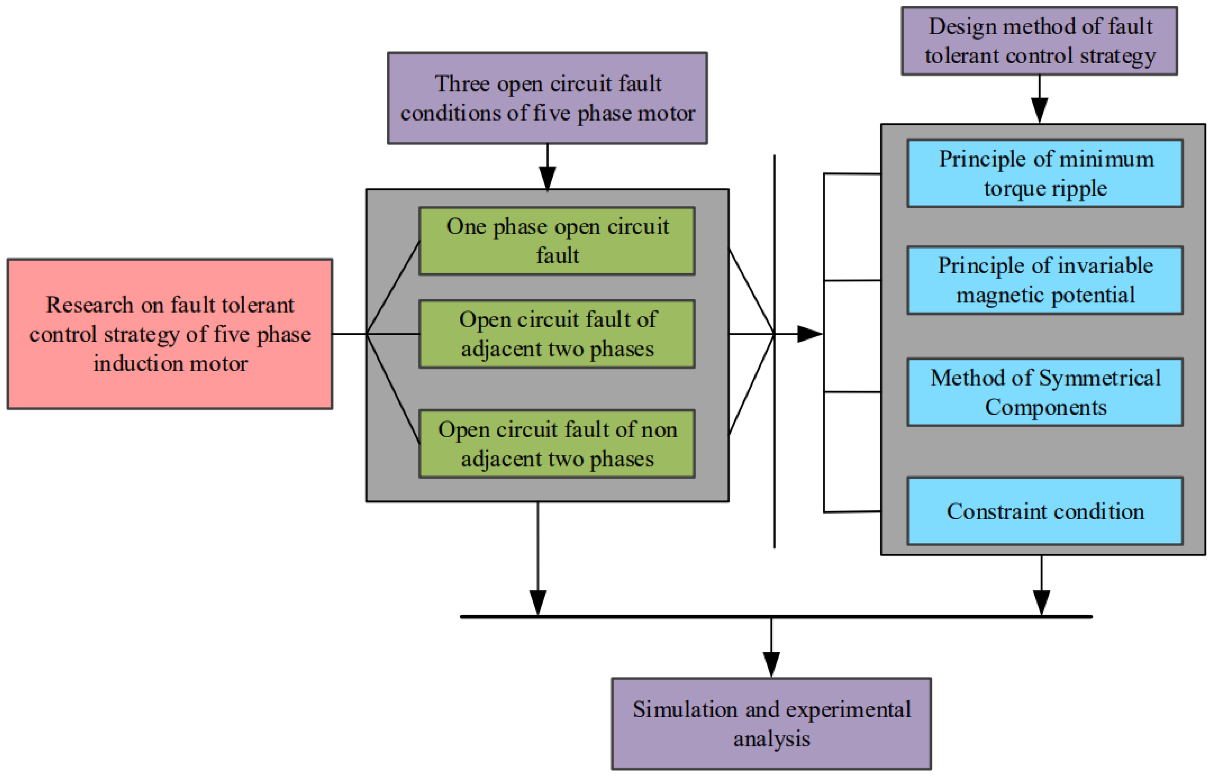
Figure 2.
Performance comparison of three fault-tolerant strategies.
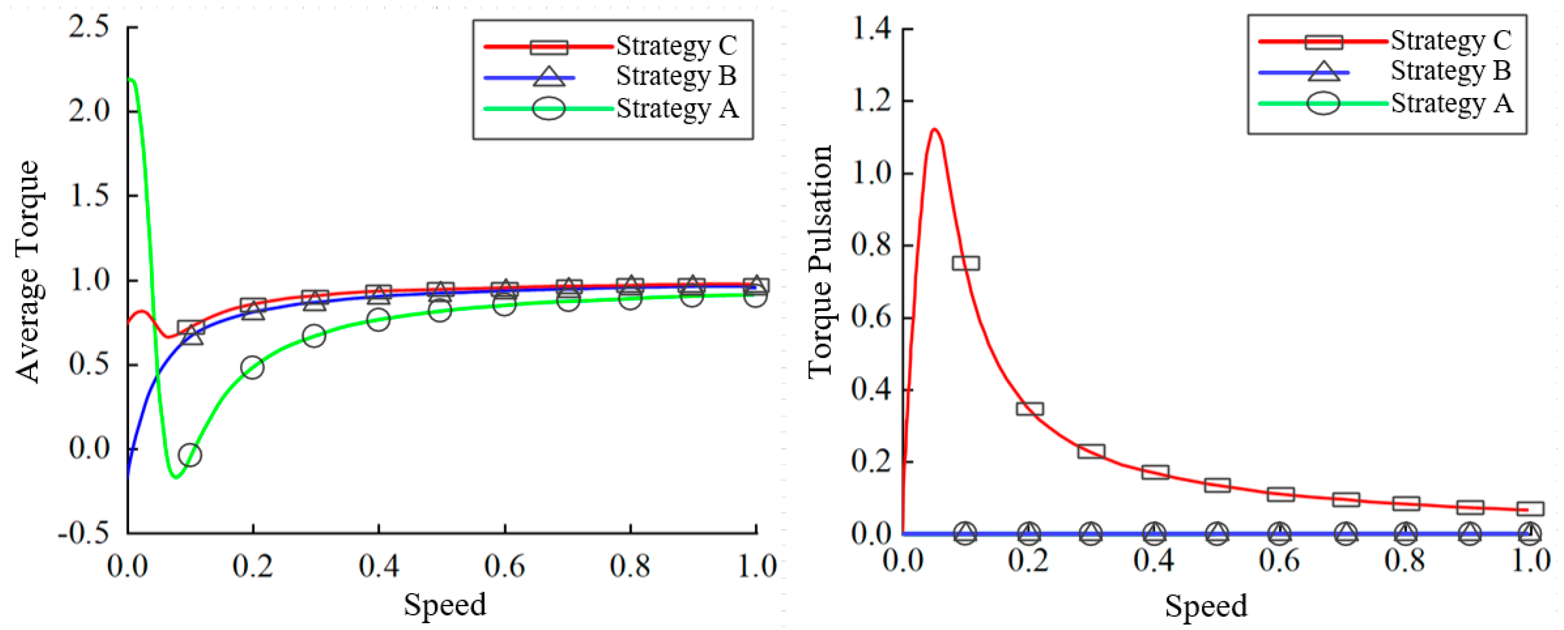
Figure 3.
Five-phase induction motor fault-tolerant control block diagram.
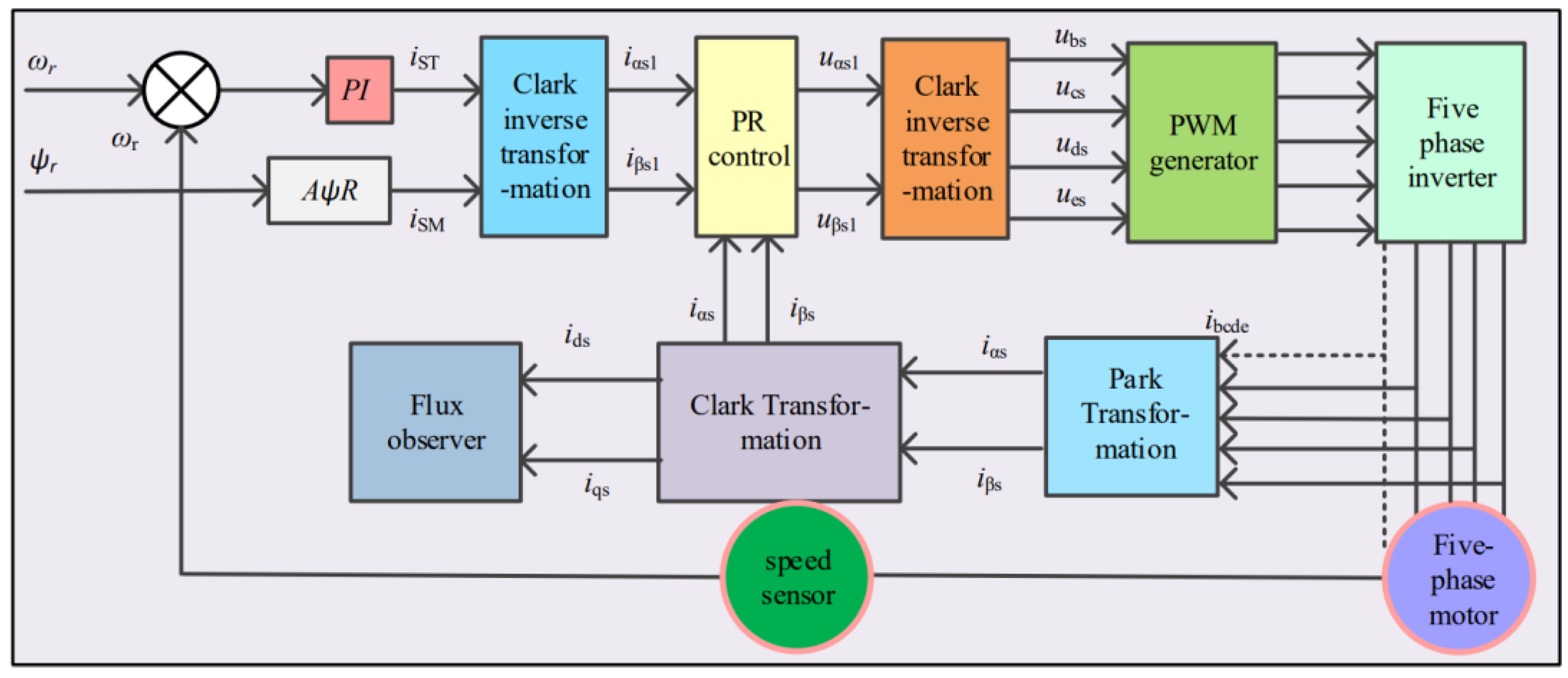
Figure 4.
Schematic diagram of remaining four-phase currents when phase A is an open-circuit fault.
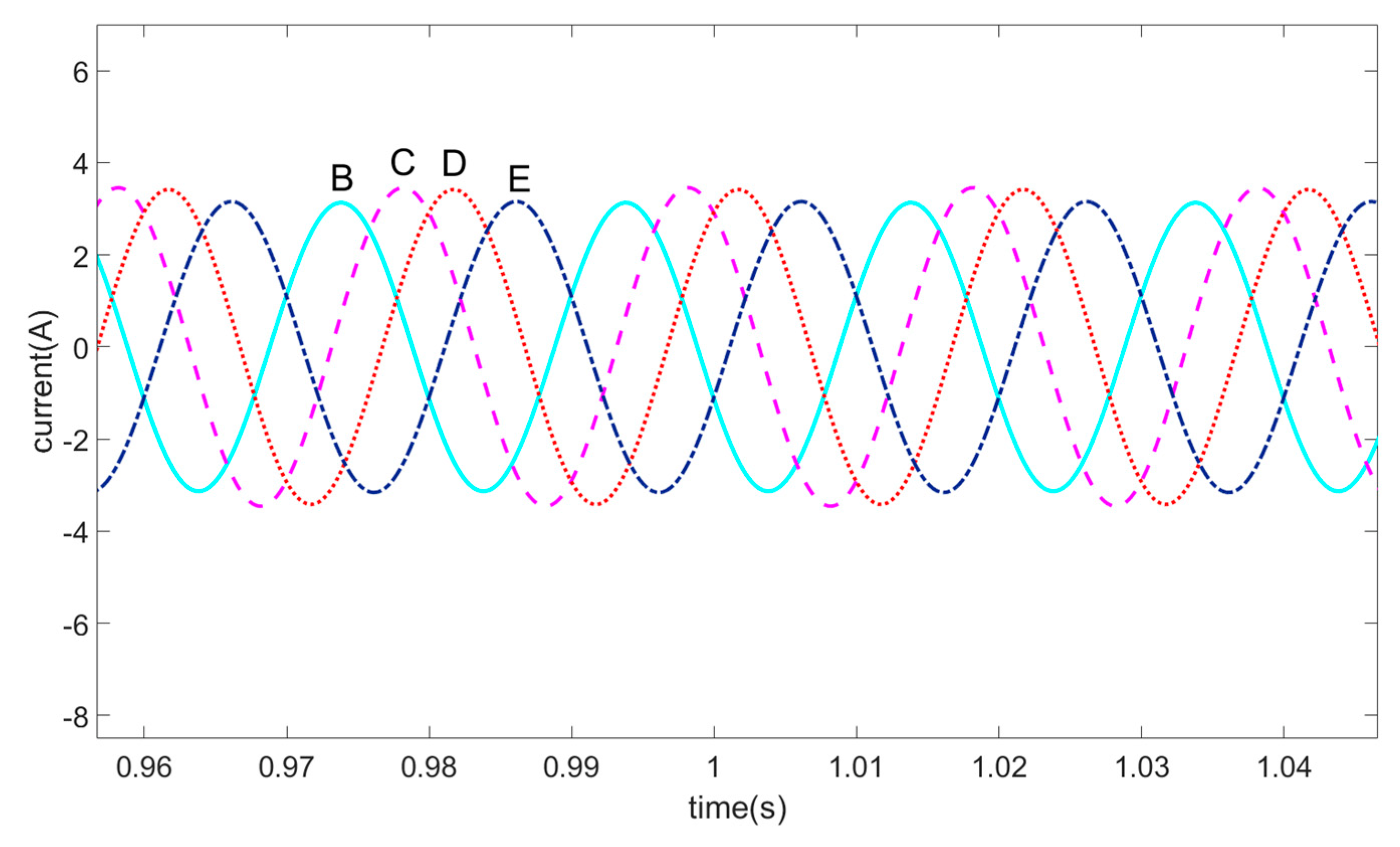
Figure 5.
Schematic diagram of remaining four-phase currents after fault-tolerant control in case of open-circuit fault of phase A.
Figure 5.
Schematic diagram of remaining four-phase currents after fault-tolerant control in case of open-circuit fault of phase A.

Figure 6.
Schematic diagram of remaining three-phase currents when phase A and B are an open-circuit fault.
Figure 6.
Schematic diagram of remaining three-phase currents when phase A and B are an open-circuit fault.
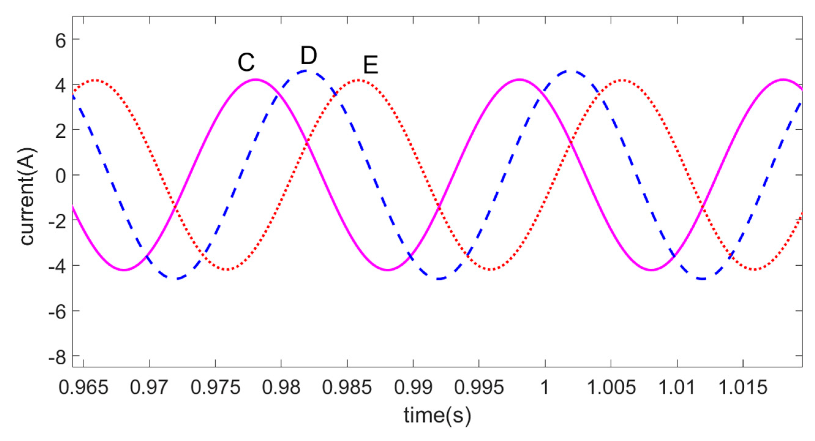
Figure 7.
Schematic diagram of remaining three-phase currents after fault-tolerant control in case of open-circuit fault of phase A and B.
Figure 7.
Schematic diagram of remaining three-phase currents after fault-tolerant control in case of open-circuit fault of phase A and B.
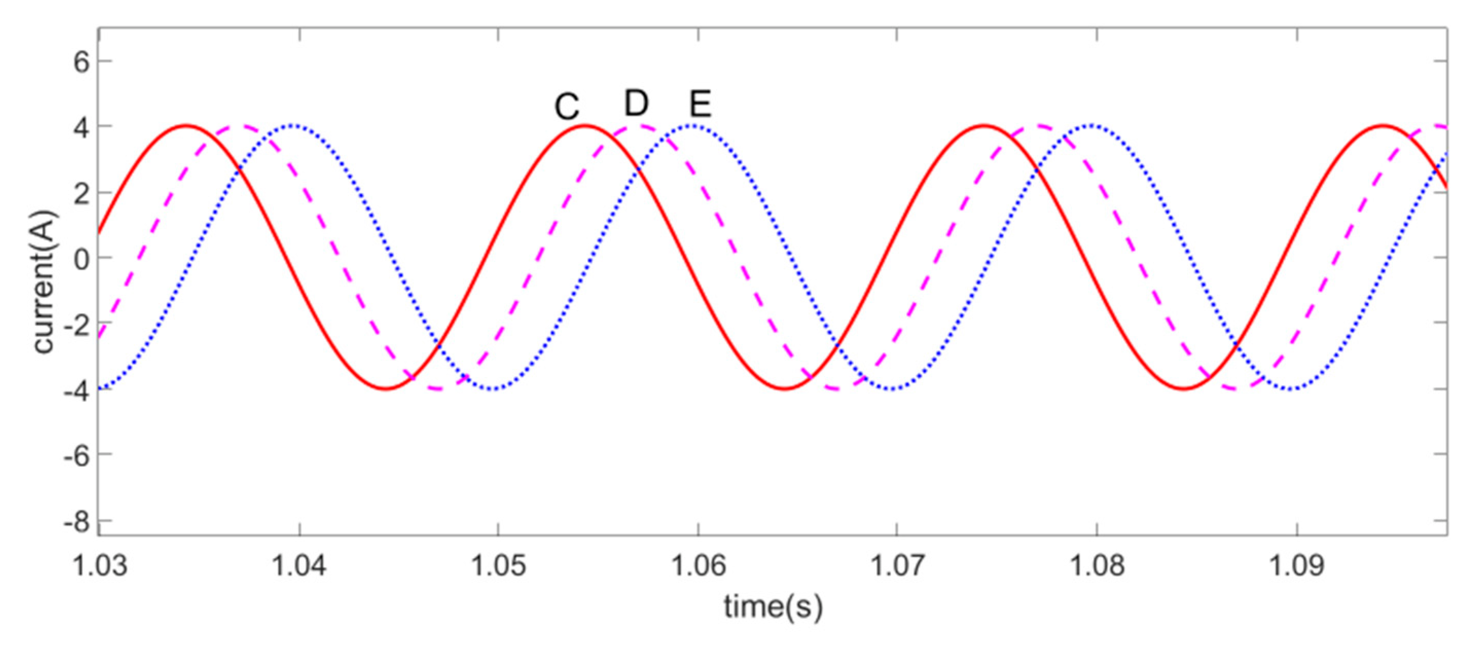
Figure 8.
Schematic diagram of remaining three-phase currents when phase A and C are an open-circuit fault.
Figure 8.
Schematic diagram of remaining three-phase currents when phase A and C are an open-circuit fault.
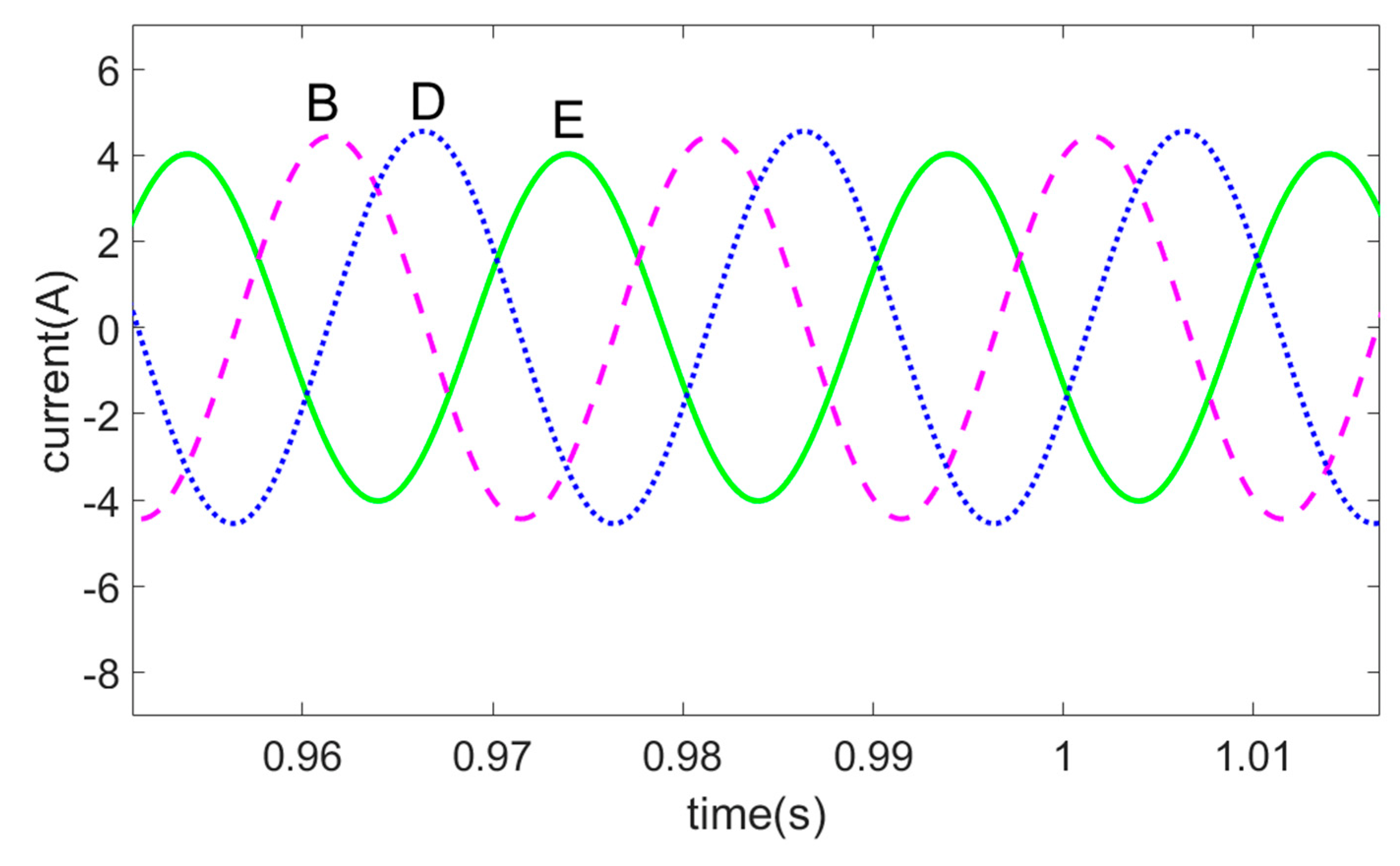
Figure 9.
Schematic diagram of remaining threephase currents after fault-tolerant control in case of open-circuit fault of phase A and C.
Figure 9.
Schematic diagram of remaining threephase currents after fault-tolerant control in case of open-circuit fault of phase A and C.

Figure 10.
Wiring diagram of open-phase experiment circuit.

Figure 11.
Waveform diagram of the lack of phase A current experiment.
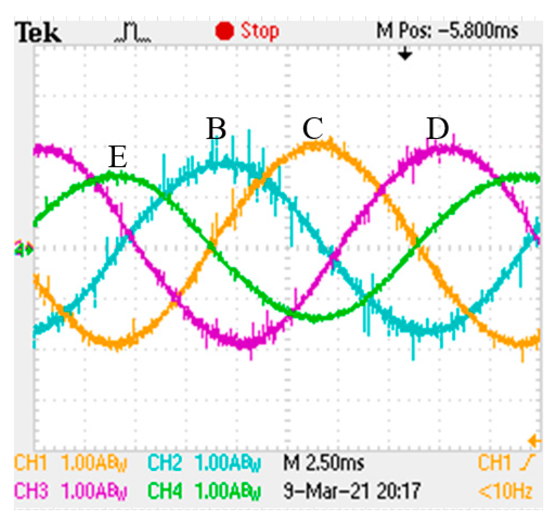
Figure 12.
Lack of phase A fault-tolerant current waveform.
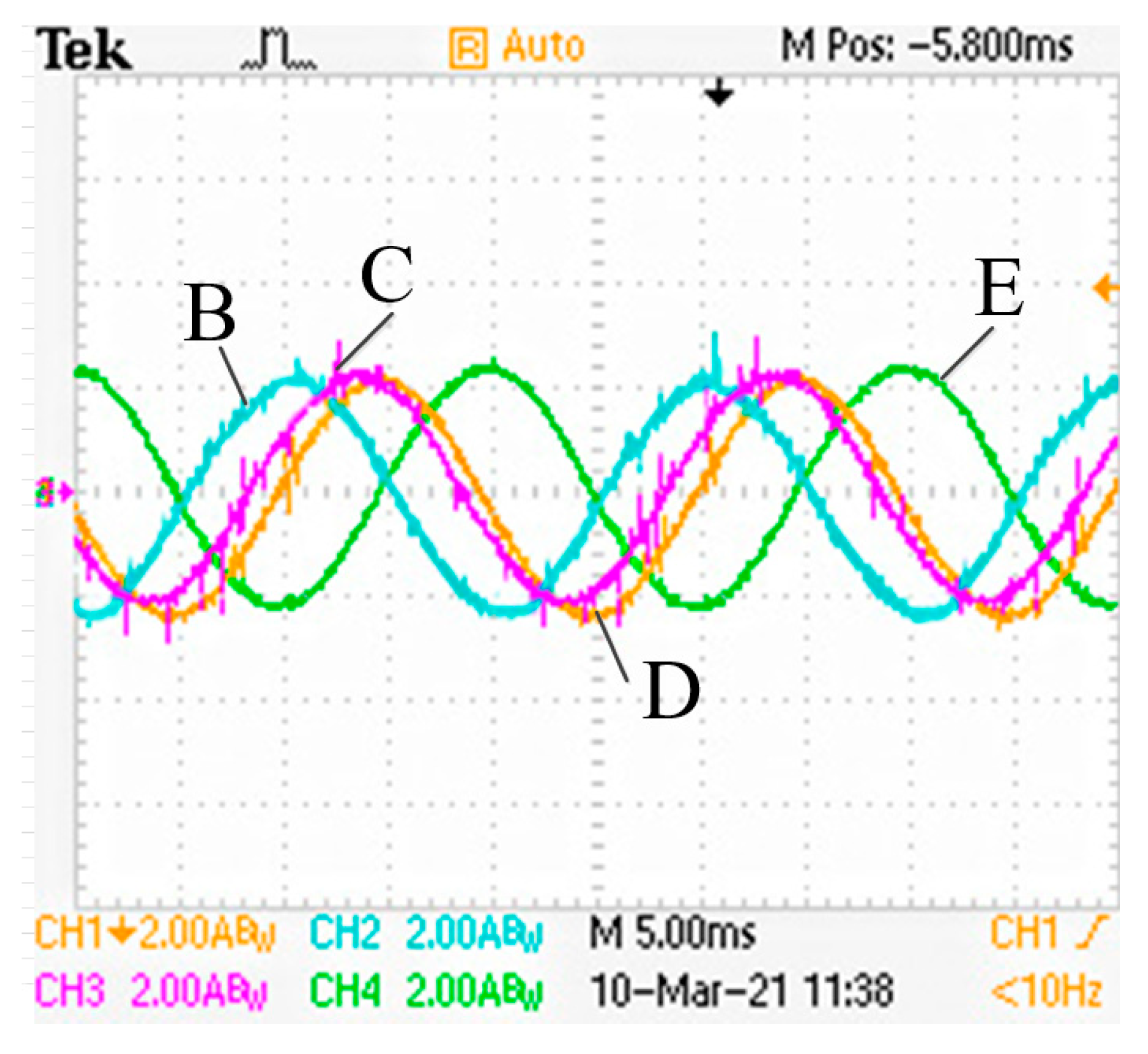
Figure 13.
Waveform diagram of the lack of phase A and B current experiment.
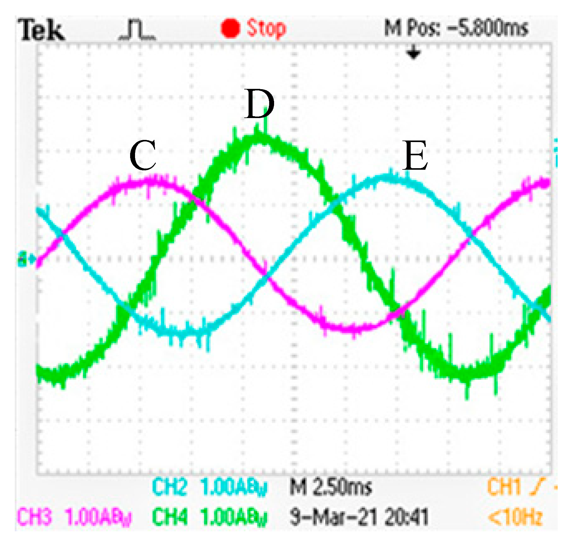
Figure 14.
Lack of phase A and B fault-tolerant current waveform.
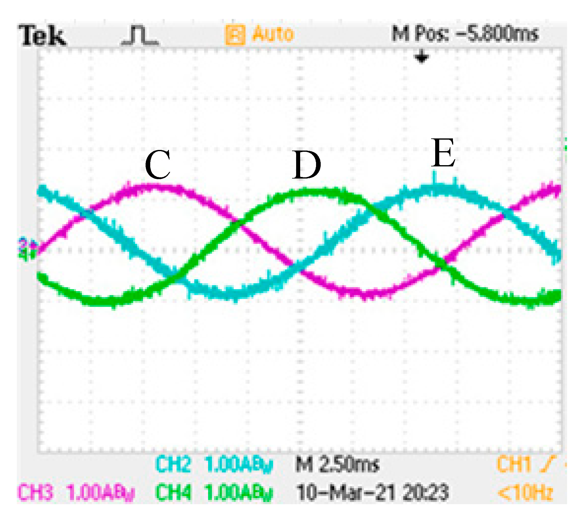
Figure 15.
Waveform diagram of the lack of phase A and C current experiment.

Figure 16.
Lack of phase A and C fault-tolerant current waveform.


Table 1.
Parameters of five-phase induction motor.
| Parameter | Unit | Value |
|---|---|---|
| Rated voltage | V | 220 |
| Stator resistance | Ω | 4.3845 |
| Rotor resistance | Ω | 5.8266 |
| Stator leakage inductance | H | 0.0185 |
| Excitation inductance | H | 0.6575 |
| Rotor leakage inductance | H | 0.0319 |
| Moment of inertia | 0.0178 |
Table 2.
Experimental parameters of five-phase induction motor.
| Parameter | Unit | Value |
|---|---|---|
| Stator inner diameter | mm | 98 |
| Stator outer diameter | mm | 175 |
| Rotor inner diameter | mm | 38 |
| Rotor outer diameter | mm | 97.5 |
| Core length | mm | 130 |
| Number of stator slots | 30 | |
| Number of slots of squirrel cage rotor | 26 | |
| Number of conductors per slot of stator winding | 57 | |
| Polar logarithm | 1 |
Table 3.
Motor speed changes after open-circuit fault of phase A and fault-tolerant control.
| Input Voltage (V) | Normal Operation (r/min) | Open Circuit Fault (r/min) | Fault Tolerant Control (r/min) |
|---|---|---|---|
| 30 V | 97 | 67 | 105 |
| 40 V | 108 | 80 | 180 |
| 50 V | 216 | 200 | 220 |
| 60 V | 463 | 458 | 564 |
| 70 V | 1385 | 588 | 600 |
| 80 V | 1430 | 686 | 1356 |
| 90 V | 1447 | 1273 | 1361 |
| 100 V | 1465 | 1308 | 1459 |
| 110 V | 1475 | 1259 | 1470 |
Table 4.
Motor speed changes after open-circuit fault of phase AB and fault-tolerant control.
| Input Voltage (V) | Normal Operation (r/min) | Open Circuit Fault (r/min) | Fault Tolerant Control (r/min) |
|---|---|---|---|
| 30 V | 97 | 0 | 0 |
| 40 V | 108 | 0 | 0 |
| 50 V | 216 | 0 | 0 |
| 60 V | 463 | 0 | 50 |
| 70 V | 1385 | 66 | 230 |
| 80 V | 1430 | 105 | 588 |
| 90 V | 1447 | 130 | 988 |
| 100 V | 1465 | 149 | 1059 |
| 110 V | 1475 | 150 | 1189 |
Table 5.
Motor speed changes after open-circuit fault of phase AC and fault-tolerant control.
| Input Voltage (V) | Normal Operation (r/min) | Open Circuit Fault (r/min) | Fault Tolerant Control (r/min) |
|---|---|---|---|
| 30 V | 97 | 60 | 80 |
| 40 V | 108 | 90 | 110 |
| 50 V | 216 | 108 | 189 |
| 60 V | 463 | 220 | 260 |
| 70 V | 1385 | 503 | 539 |
| 80 V | 1430 | 514 | 917 |
| 90 V | 1447 | 726 | 1262 |
| 100 V | 1465 | 710 | 1436 |
| 110 V | 1475 | 719 | 1466 |
Publisher’s Note: MDPI stays neutral with regard to jurisdictional claims in published maps and institutional affiliations. |
© 2022 by the authors. Licensee MDPI, Basel, Switzerland. This article is an open access article distributed under the terms and conditions of the Creative Commons Attribution (CC BY) license (https://creativecommons.org/licenses/by/4.0/).
Share and Cite
MDPI and ACS Style
Xu, H.; Zhao, J.; Yang, L.; Chen, H.; Luo, X.; Zhang, S. Research on Open Circuit Fault Modeling and Fault Tolerant Control Strategy of Five-Phase Induction Motor. Processes 2022, 10, 1891. https://doi.org/10.3390/pr10091891
AMA Style
Xu H, Zhao J, Yang L, Chen H, Luo X, Zhang S. Research on Open Circuit Fault Modeling and Fault Tolerant Control Strategy of Five-Phase Induction Motor. Processes. 2022; 10(9):1891. https://doi.org/10.3390/pr10091891
Chicago/Turabian StyleXu, Hao, Jinghong Zhao, Lv Yang, Hansi Chen, Xiangyu Luo, and Shuheng Zhang. 2022. "Research on Open Circuit Fault Modeling and Fault Tolerant Control Strategy of Five-Phase Induction Motor" Processes 10, no. 9: 1891. https://doi.org/10.3390/pr10091891
Note that from the first issue of 2016, this journal uses article numbers instead of page numbers. See further details here.