Article

Numerical Study on Pile Group Effect and Carrying Capacity of Four-Barreled Suction Pile Foundation under V-H-M Combined Loading Conditions

1
State Key Laboratory of Coastal and Offshore Engineering, Dalian University of Technology, Dalian 116024, China
2
Offshore Oil Engineering Co., Ltd., Tianjin 300451, China
*
Author to whom correspondence should be addressed.
Processes 2022, 10(11), 2459; https://doi.org/10.3390/pr10112459
Submission received: 29 October 2022 / Revised: 16 November 2022 / Accepted: 17 November 2022 / Published: 20 November 2022
(This article belongs to the Special Issue Advances in Numerical Modeling for Deep Water Geo-Environment)

Abstract

:
Multi-barreled composite foundations are generally used in offshore oil platform structure. However, there is still a lack of theoretical analyses and experimental research. This paper presents the results of a three-dimensional finite element analysis of a four-barreled suction pile foundation in heterogeneous clay foundation. The pile group effect and carrying capacity are numerically simulated. The effects of different pile embedment depths, pile spacings and non-uniformity coefficients of clay on the pile group effect are studied. Considering the changes in the foundation carrying capacity under vertical, horizontal and bending moment coupling loads, the foundation carrying capacity envelopes under horizontal and moment (H-M) and vertical, horizontal and moment (V-H-M) loading modes are drawn. The results show that pile spacing and embedment depth have great influence on the pile group effect. The bearing capacity envelope of foundations under V-H-M loading mode is greatly affected by vertical load V. This can provide a reference for the selection of pile spacing and embedded depth in practical engineering design. Furthermore, the stability of foundations can be evaluated according to the relative relationship between design load and failure envelope.

1. Introduction

With the rapid development of oil and gas exploration in deep waters, the conventional gravity type and jacket type of shallow-sea offshore engineering foundation structures are no longer applicable. Suction pile foundations have been widely used in offshore oil production platform foundation structures in recent years because of the advantages of their light weight, simple construction and recyclable use [1]. Compared with single-barreled suction pile foundations, four-barreled suction pile foundations have higher carrying capacity and better stability. A key problem in the design and construction of offshore oil platforms is determining the overall failure mode and carrying capacity characteristics of multi-bucket composite structures in complex marine environments so as to evaluate the stability of offshore oil platforms and avoid the loss of peoples’ lives and property. Evaluating the failure envelope of foundation carrying capacity is an effective method to determine the limit state of foundation carrying capacity under composite loading mode. The so-called foundation failure envelope refers to a convex surface formed by the combination of various load components in the three-dimensional load space when the foundation reaches the overall failure or limit equilibrium state under the combined load. When the load combination is within the failure envelope, the foundation is in a stable state; otherwise, the foundation is unstable.
Many researchers have studied the bearing characteristics of bucket foundations on soft soil foundations by theoretical calculation [2,3,4,5], experimental research [6,7,8] and numerical simulation [9,10,11,12]. These researchers consider the influence of foundation shape, foundation burial depth, soil strength heterogeneity and other factors on the bearing performance of bucket foundations. However, only a few researchers have explored the bearing characteristics of multi-barreled foundations. The pile group effect exists due to the interaction between multi-barreled suction pile foundations. Gourvenec and Jensen [13] used the 2D finite element method to study the group effect of two-skirted foundations in homogeneous clay. The results show that the group effect of vertical bearing capacity can be ignored, and that the horizontal bearing capacity increases significantly with the increase inin spacing and ultimately tends to be stable. Kim and Hung [14] used the finite element method to analyze the carrying characteristics of the foundation under different L/Ds (where L is the skirt length of the foundation and D is the diameter of the foundation) and S/D ratios (where S is the spacing between the individual piles of the foundation, as is shown in Figure 1) for the tripod foundation of offshore wind turbines, and verified the pile group effect of the L/D and S/D ratios on the tripod foundation.
A great deal of research has also been carried out on the carrying capacity of foundations under combined loading conditions. Zhang and Kong [15] carried out centrifuge model tests on bucket foundations and pipe pile foundations, respectively. They agreed that the foundation is often more vulnerable to instability under bending moment load or composite loading conditions which include bending moment load components. Gourvenec and Mana [16] obtained the foundation carrying capacity envelope of strip foundations with an apron board at different buried depths for homogeneous and heterogeneous foundations under different loads using finite element calculation and proposed an expression that can reasonably estimate the carrying capacity of foundations.
So far, the existing research mainly focuses on the tripod bucket foundations of offshore wind turbines, while there is relatively less research on four-barreled suction pile foundations. Andersen et al. [17] reported field trials on a group of 2 × 2 adjacent caissons and cyclic loading in a lightly over-consolidated soft soil. They found that the ultimate bearing capacity can be reduced by 18–34%. Zhu et al. [18] conducted a centrifugal model test of uplift bearing capacity of four-barreled foundations and derived an empirical model to quantify the effect of caisson groups. In summary, there are few studies on the pile group effect of four-barreled suction pile foundations under different direction loadings and there is a lack of research on the joint working mechanism under a combined loading mode.
In this paper, a three-dimensional finite element model is established to numerically simulate the pile group effect and carrying capacity of a four-barreled suction pile foundation in clay foundation, and the validity is verified. A linear-elastic perfectly plastic model obeying the Tresca failure criterion is used to simulate the stress–strain response of clay under undrained conditions. It is assumed that the Young’s modulus and undrained shear strength of cohesive soil increase linearly with soil depth. The foundation was subjected to vertical, horizontal, bending moment and torque loading, and the embedded depth and pile spacing were parametrically analyzed. The carrying capacity of the foundation under a coupling load is also analyzed using the fixed displacement ratio loading method, and the carrying capacity envelopes under H-M and V-H-M loading modes are drawn. Therefore, it is hoped that through this paper’s research, a reference for the structural design and construction of the suction pile foundation of a submarine oil production platform can be provided to ensure the safety and stability of the foundation’s working state.

2. FE Numerical Model

2.1. Model Construction and Material Properties

Aimed at the four-barreled suction pile foundation structure of subsea oil production platforms, a three-dimensional finite element model of four-barreled suction pile foundations is established by ABAQUS commercial FE software. The study of Hung and Kim [9] showed that D had no effect on the standardized carrying capacity. Therefore, in this study, the D of all models is 10 m and the wall thickness is 25 mm, which is the common thickness of steel cylinder foundations. The four suction piles adopt the same geometric size and are squarely distributed in the plane range. As shown in Figure 1, the rigid connection between the piles is constrained by the top surface in the same plane. Therefore, the relative displacement between the piles is ignored [19]. The finite element model of the calculation area and mesh division is shown in Figure 2. In order to eliminate the boundary effect, the calculation area takes 10 times the pile spacing in the radial direction and 5 times the pile length in the depth direction. The boundary conditions allow for no vertical or lateral soil movement at the soil base and no horizontal movement at the vertical boundaries [20]. The first-order, eight-node linear brick, reduced integration element C3D8R was used to model the soil [21,22,23,24]. In order to ensure the calculation’s accuracy and convergence, the finite element mesh of soil around pile is more compact.
The material of the four-barreled suction pile foundation is steel and its stiffness is much higher than that of the soil. Therefore, it is assumed that the pile is a completely elastic steel material, and the linear elastic constitutive model is adopted. The elastic constants are E = 210 GPa and υ = 0.3. The elastic perfectly plastic constitutive model based on the Tresca failure criterion is used in the description of the stress–strain relationship of soil [25]. It is assumed that the undrained shear strength increases linearly with depth. The formula is as follows [26]:
S u = S u m + k Z
In the formula, Sum is the undrained shear strength of the surface, Z is the depth below the surface, and k is the growth rate of strength with depth. Previous studies have shown that the carrying capacity coefficient of foundations does not depend on a single parameter of Sum or k, but depends on the normalized non-uniformity coefficient kD/Sum [27]. Therefore, the non-uniformity of clay is defined by kD/Sum. For normally consolidated clay, k = 1.25 kPa/m, and the undrained shear strength of the surface is almost 0. In order to avoid the convergence difficulty of finite element calculation, Sum = 1.25 kPa and elastic modulus E = 500 Su, the USDFLD subroutine is used to complete the numerical implementation in ABAQUS. The Poisson’s ratio is chosen to be 0.499 to simulate the constant volume response of clay under undrained conditions.
When the suction pile foundation in clay is subjected to load, passive suction is generated inside it to prevent the soil inside the pile from separating from the pile. Therefore, in order to consider the influence of passive suction, it is assumed that the contact interface between the pile and the soil is completely rough and bonded [20,28,29]. The contact surface between the outside of the pile and the soil of the suction pile foundation adopts Coulomb friction, and the friction coefficient is set to u = 0.35 [30].

2.2. Validation of the Numerical Model

For the four-barreled suction pile foundation in clay foundation, there is no systematic theoretical analytical solution and test results at present. In order to verify the validity of the three-dimensional finite element analysis model adopted, this paper refers to the tripod bucket foundation [14], using the same barrel geometry, plane layout, soil constitutive relationship and contact parameters of the barrel and soil as described in Chapter 1 above. The finite element analysis model of the three-dimensional tripod bucket foundation is established, and the carrying capacity under monotonic load is calculated and compared with the existing calculation results, as shown in Figure 3.
It can be seen from Figure 3 that the error between the calculation results for vertical carrying capacity and horizontal carrying capacity and the existing research results is within 5%. The tripod bucket foundation established according to the modeling method in this paper can reliably calculate the carrying capacity of suction pile foundations in clay foundations. Therefore, the three-dimensional finite element analysis model used in this study can reliably and accurately evaluate the carrying capacity of four-tube suction pile foundations in clay foundations.

3. Loading Carrying Capacity of the Foundation

3.1. Determination of Loading Carrying Capacity

In order to obtain the ultimate carrying capacity of four-barreled suction pile foundations, the displacement control analysis method is used, which is suitable for obtaining the ultimate carrying capacity of foundations [31,32]. Vertical displacement (v), horizontal displacement (h) and angular displacement (θ) are applied at the geometric center RP (load reference point) of the upper surface of the four-barreled suction pile foundation until either the reaction force in the corresponding direction does not continue to increase with the increase in displacement or tends to be stable. The displacement and reaction force of the reference point in this direction are extracted, and the load–displacement relationship curve of the foundation is drawn. The method plots two tangential lines along the initial and latter portions of the load–displacement curve [33]. The load corresponding to the intersection point of these two lines is considered as the carrying capacity, as is shown in Figure 4.
Figure 5 shows an example of obtaining the H-M failure envelope using the fixed displacement ratio method [34]. The so-called fixed displacement ratio method involves taking the ratio of the displacement increments in the two directions as a constant for displacement control loading until the load components in both directions reach the limit value. At this time, the loading path converges to a point on the envelope. Through multiple fixed displacement ratio loading tests, a series of points on the envelope surface can be obtained to construct the foundation carrying capacity failure envelope surface of the bucket foundation. However, this method requires multiple loadings to fit a complete envelope surface, especially when the form of the envelope surface is unknown.

3.2. Definition of Load and Displacement

The sign definitions are provided in Table 1. The definitions were modified based on Gourvenec [35].
In Table 1, N*(F) and N*(S) indicate the single- and four-barreled suction pile foundations’ dimensionless loads, respectively. A(*) is the cross-sectional area of single- and four-barreled suction pile foundations. Vult, Hult, Mult and Tult are the vertical, horizontal, moment and torque carrying capacities of single- and four-barreled suction pile foundations, respectively. Suo is the undrained shear strength of clay at a depth of D/4 below the skirt tip level.

4. Pile Group Effect

4.1. Under Vertical Loading Condition

The relationship of the vertical dimensionless load NV(F) and pile group effect coefficient EV with different L/D and S/D ratios is shown in Figure 6. The NV(F) increases with the increase in L/D ratios, and the EV decreases with the increase in L/D ratios. From the diagram, it can be seen that as the S/D ratios increases, the vertical dimensionless load curve gradually stabilizes, and the larger the aspect ratio, the greater the S/D ratio needed to achieve this steady state. When the S/D ratio is less than 2, the EV varies from 0.96 to 1. When the S/D ratio is greater than 2, the EV is 1.
Figure 7 shows the displacement contours under vertical loading of the four-barreled suction pile foundation with the L/D ratio = 1 and the S/D ratios of 0.5, 1 and 2. When the S/D ratio is less than 1, the soil around the adjacent suction pile foundation interacts under the vertical load, resulting in a decrease in carrying capacity. When the S/D ratios = 2, the interaction effect is weakened or even disappears, and the pile group effect coefficient EV is gradually stabilized at 1.

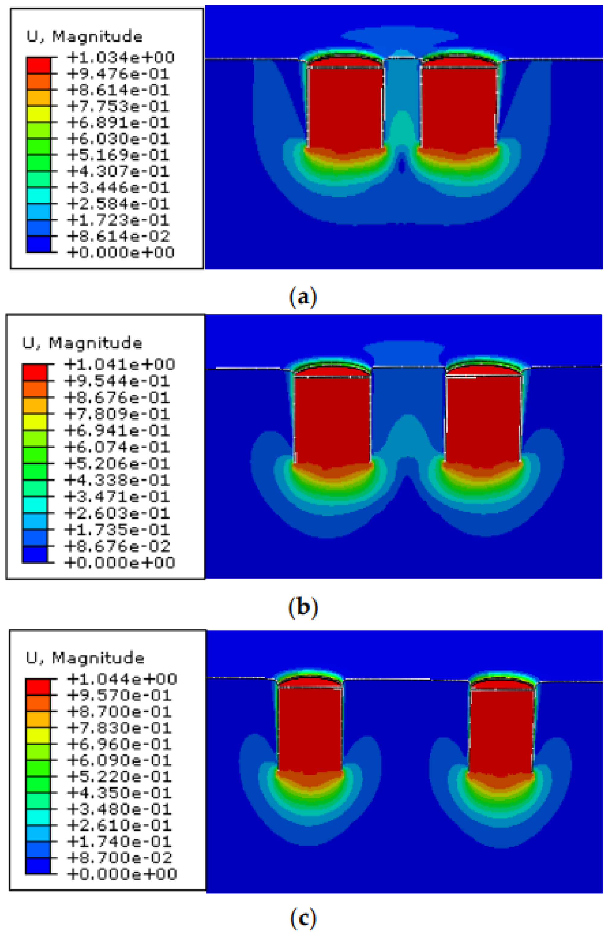
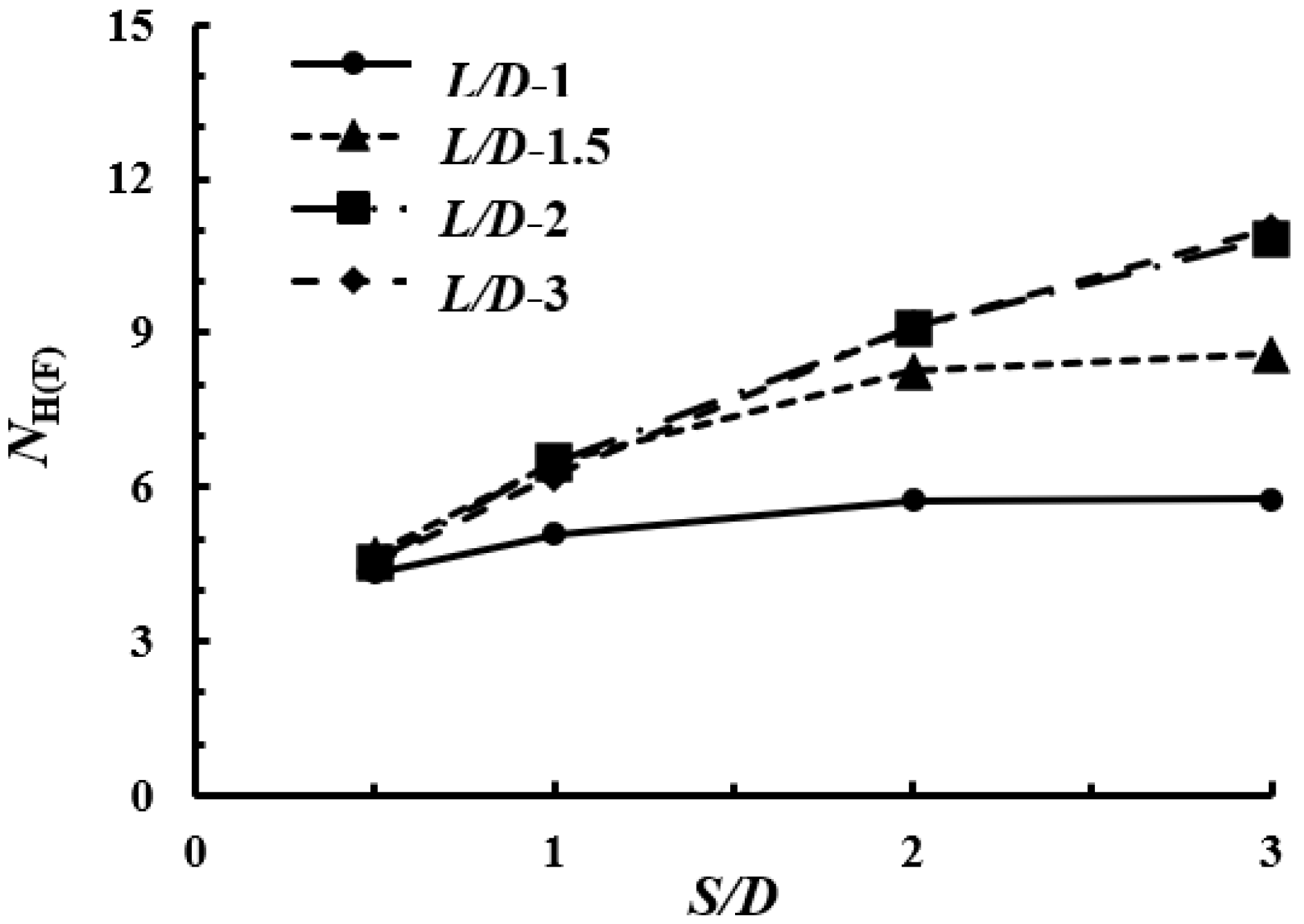
4.2. Under Horizontal Loading Condition

Figure 8 shows the relationship of the horizontal dimensionless load NH(F) and pile group effect coefficient EH with different L/D and S/D ratios. It can be seen from the figure that the horizontal dimensionless load NH increases with the increase in the L/D and S/D ratios. As S/D ratios increase, the final curve tends to be stable, and the larger the L/D ratios, the larger the S/D ratio needed to achieve this steady state, which is the same as the vertical dimensionless load.
Figure 9 shows the displacement contours of single-barreled and four-barreled suction pile foundations under horizontal load. It is worth noting that the single-barreled suction pile foundation rotates under horizontal load, and its rotation center is located inside the pile. For the four-barreled suction pile foundation with the S/D ratio of 1, when L/D = 1, the four-barreled suction pile foundation only moves horizontally under the horizontal load. This conclusion is similar to that developed in the work of Kim and Hung [11], which reported that when the S/D ratio is greater than a certain value, the horizontal dimensionless load of the tripod bucket foundation is similar to the dimensionless load of the fixed single-barreled rotation degree of freedom. When the L/D ratio is 2 or 3, the four-barreled suction pile foundation rotates, and its rotation center is located at the tip of the pile. Therefore, under a horizontal load, due to the different modes of four-barreled suction pile foundations with different L/D and S/D ratios used to mobilize the surrounding soil to allow it to resist deformation and failure, a specific expression cannot be used to characterize the pile group effect coefficient of the horizontal carrying capacity.

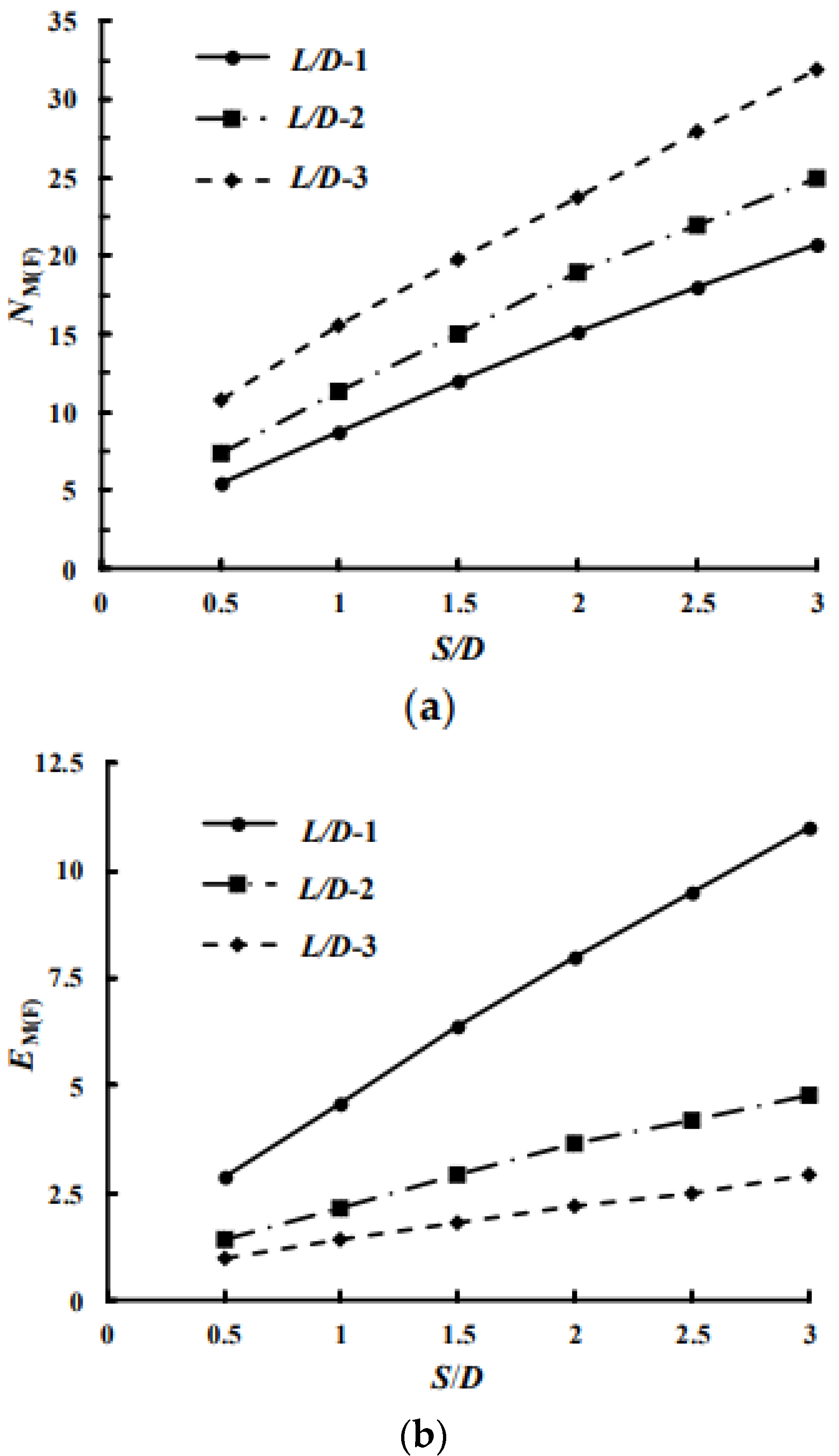
4.3. Under Moment Loading Condition

Figure 10 shows the moment dimensionless load NM(F) and the pile group effect coefficient EM with S/D and L/D ratios. The moment dimensionless load NM(F) increases with the increase in the L/D ratios, and EM decreases with the increase in the L/D ratios, both of which increase with the increase in the S/D ratios.
By calculating the bending capacities under various working conditions, an equation for calculating the bending capacity of four-barreled suction pile foundations is proposed, which can be obtained by multiplying the moment dimensionless load NM(S) of single-barreled suction pile foundations with the pile group effect coefficient EM:
Mult = EMNM(S)A(F)DSuo
E M = 1 + α ( S D ) β
α = 0.7 e 0.2 ( L D )
β = 10.8 e L D
Figure 11 shows the displacement contours of the four-barreled suction pile foundation under moment loading. It can be seen from the figure that the suction pile rotates as a whole, and its rotation center is located between adjacent suction piles.

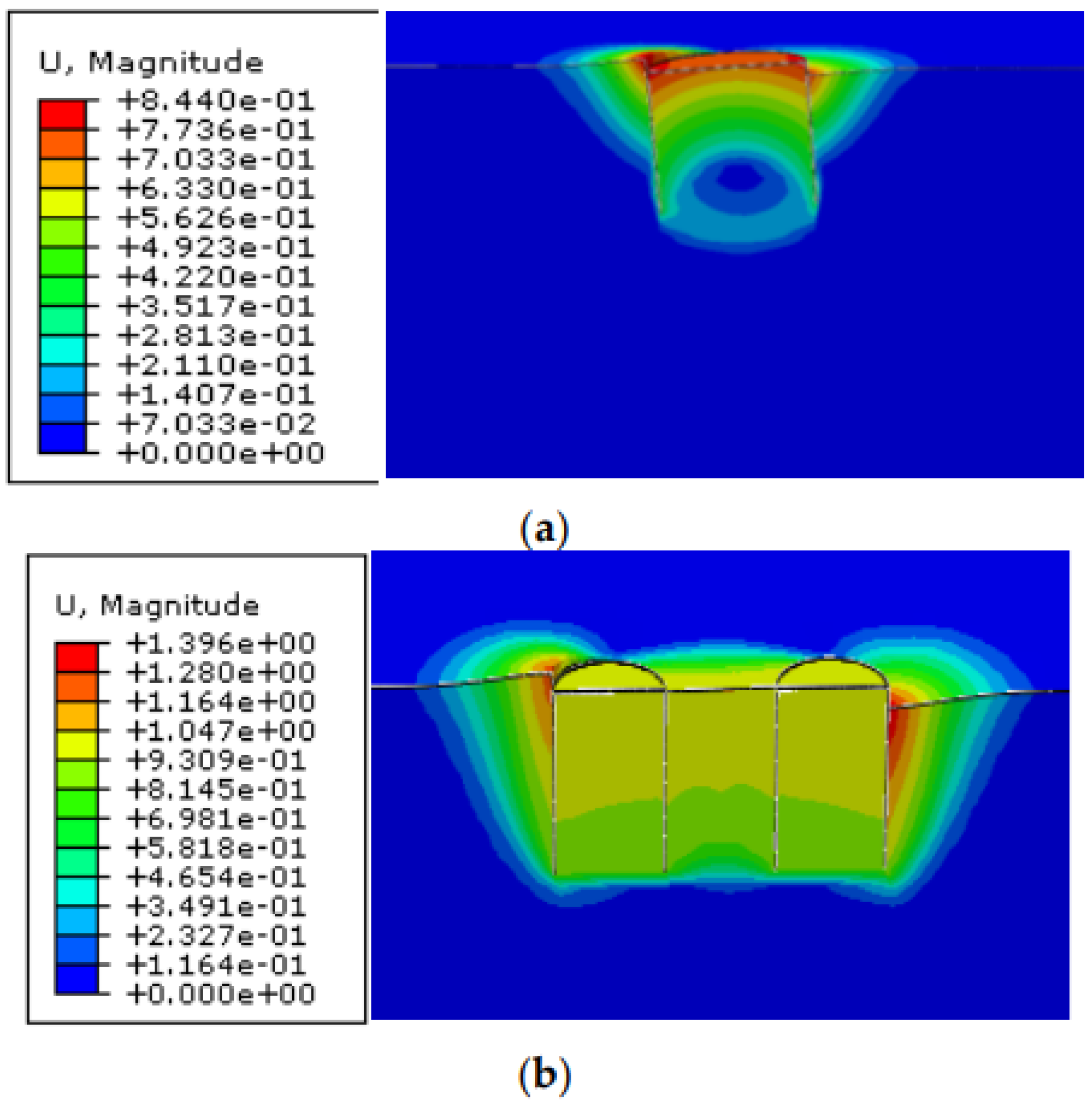
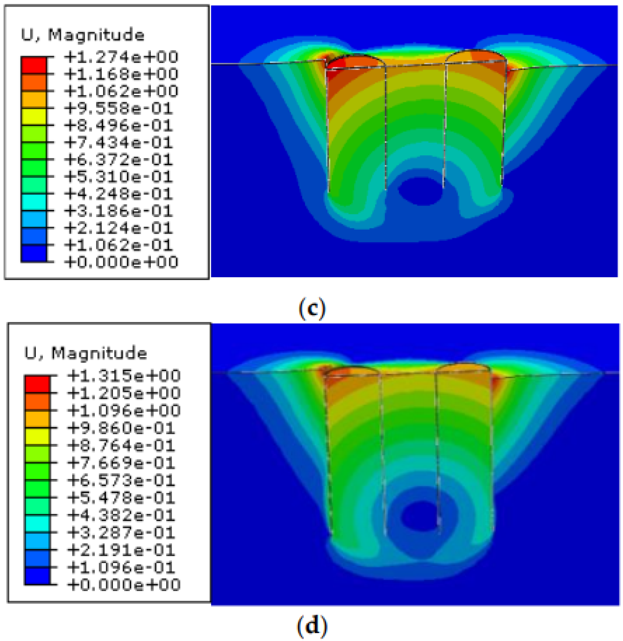
4.4. Under Torsional Loading Condition

Figure 12 shows the torsional dimensionless load NT(F) with S/D and L/D ratios. The NT(F) increases with the increase in S/D and L/D ratios.
Figure 13 shows the displacement contours of the four-barreled suction pile foundation under torsional loading. Since the single-barreled suction pile foundation rotates around the central axis of the pile when subjected to torsional load, its carrying capacity contribution mainly comes from the friction between the foundation and the soil. The four-barreled suction pile foundation rotates around the reference point RP central axis, and the pile body moves horizontally.
Therefore, its torsional carrying capacity can be calculated by multiplying the horizontal carrying capacity of the single-barreled suction pile foundation with the fixed rotational degree of freedom by the torque length:
T u l t = E T 4 H u l t = E T N H ( S ) A ( F ) D S u o
where ET is the pile group effect coefficient of the torsional carrying capacity. Figure 14 shows the ET with L/D and S/D ratios of torsional carrying capacity, which decreases with the increase in L/D ratio and gradually tends to 1 with the increase in S/D ratio.

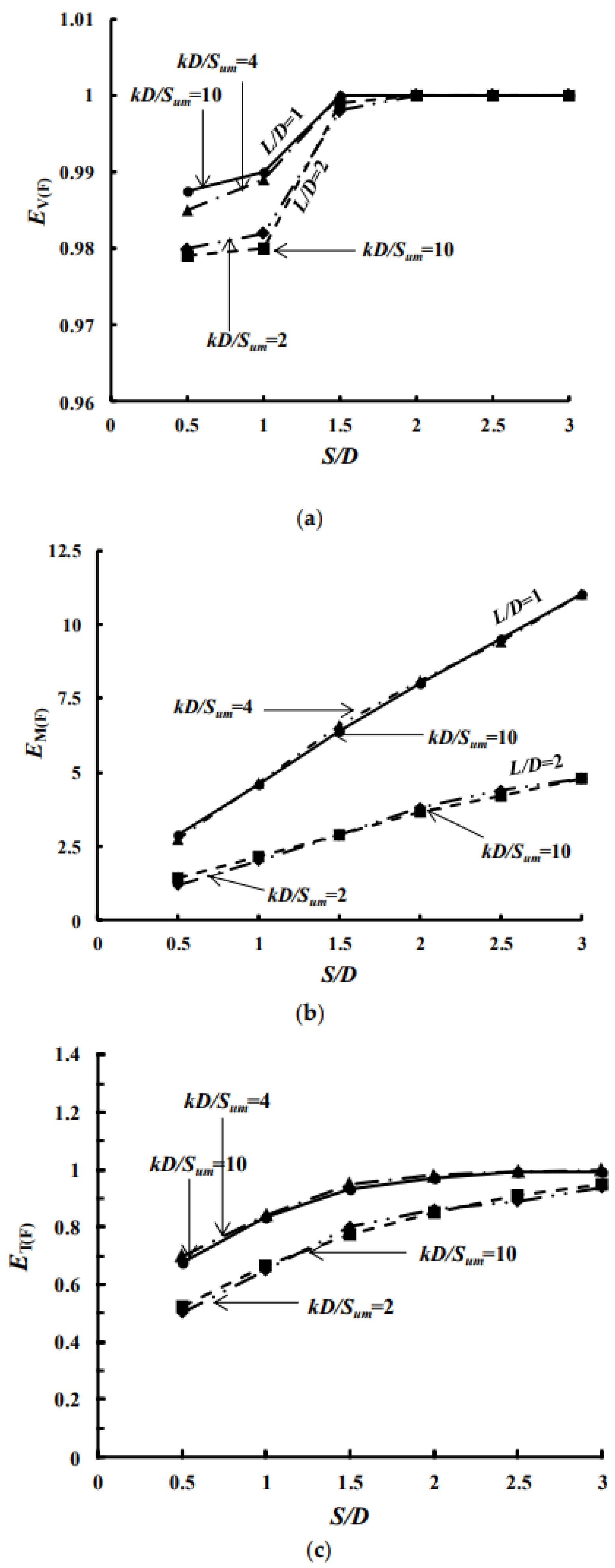
4.5. Effect of Non-Homogeneity of Clay on Group Efficiency

Studies have shown that clay heterogeneity has no significant effect on the pile group effect coefficient of the carrying capacity of tripod bucket foundations [11]. In this paper, the effect of non-homogeneity of clay on the group efficiency of four-barreled suction pile foundations is analyzed. We set kD/Sum to 2 and 4, and the specific parameters are shown in Table 2.
Figure 15 shows the comparison of pile group effect coefficients of four-barreled suction pile foundations under different clay non-homogeneity coefficients kD/Sum. It can be seen that the non-homogeneity of clay has little effect on the pile group effect coefficient of the carrying capacity of four-barreled suction pile foundations.

5. Carrying Capacity Envelope under Combined Loading Conditions

5.1. Combined H-M Capacity Envelope

A series of displacement loading scenarios are carried out using the fixed displacement ratio method to obtain the H-M load space carrying capacity envelope. Figure 16 shows the dimensionless carrying capacity envelope of a four-barreled suction pile foundation under different L/D and S/D ratios. It can be seen from the figure that under the combined action of horizontal and bending moment loads, the foundation carrying capacity envelope of the H-M load space shows obvious asymmetry, and as the L/D ratio increases, the asymmetry of the envelope is more obvious, and the size is larger. As the S/D ratio increases, the bending capacity increases significantly. But for the horizontal carrying capacity, due to the gradual weakening of the pile group effect, with the S/D ratio increases from 2 to 3, the impact on the horizontal carrying capacity is not significant.

5.2. Combined V-H-M Capacity Envelope

The failure envelope characteristics of a four-barreled suction pile foundation with different S/D ratios in the V-H-M load space are studied. Firstly, different proportions of vertical loads are directly applied at the reference point RP of the foundation, which is used as the initial state of displacement control loading. Keeping the vertical load unchanged, the fixed displacement ratio loading in the H-M load space is carried out.
It can be seen from Figure 17 that the size of the failure envelope of the foundation carrying capacity under the H-M load space of the four-barreled suction pile foundation decreases with the increase in the vertical load. Taking S/D = 3 as an example, the vertical load increases from V = 0.5 Vult to V = 0.75 Vult, the moment capacity is reduced by 57%, and the horizontal carrying capacity is reduced by 9%. As the foundation structures of submarine oil production platforms often bears large vertical loads, it is necessary to comprehensively consider structural weight and carrying capacity in the design and construction process.

6. Conclusions

Through a series of three-dimensional finite element analyses, the group effect of four-barreled suction pile foundations in clay foundations under undrained conditions and the carrying characteristics under combined loading modes are studied. The following conclusions are drawn:
(1)
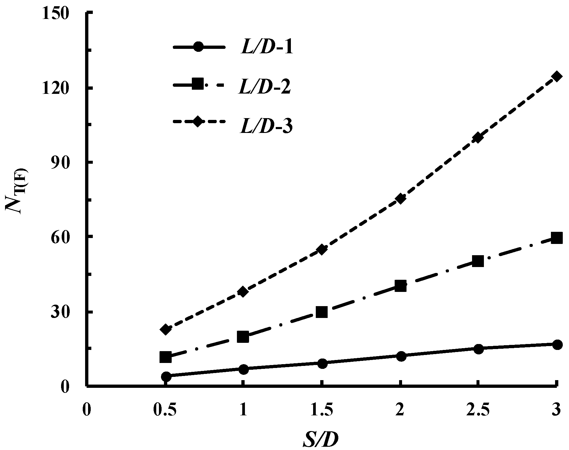
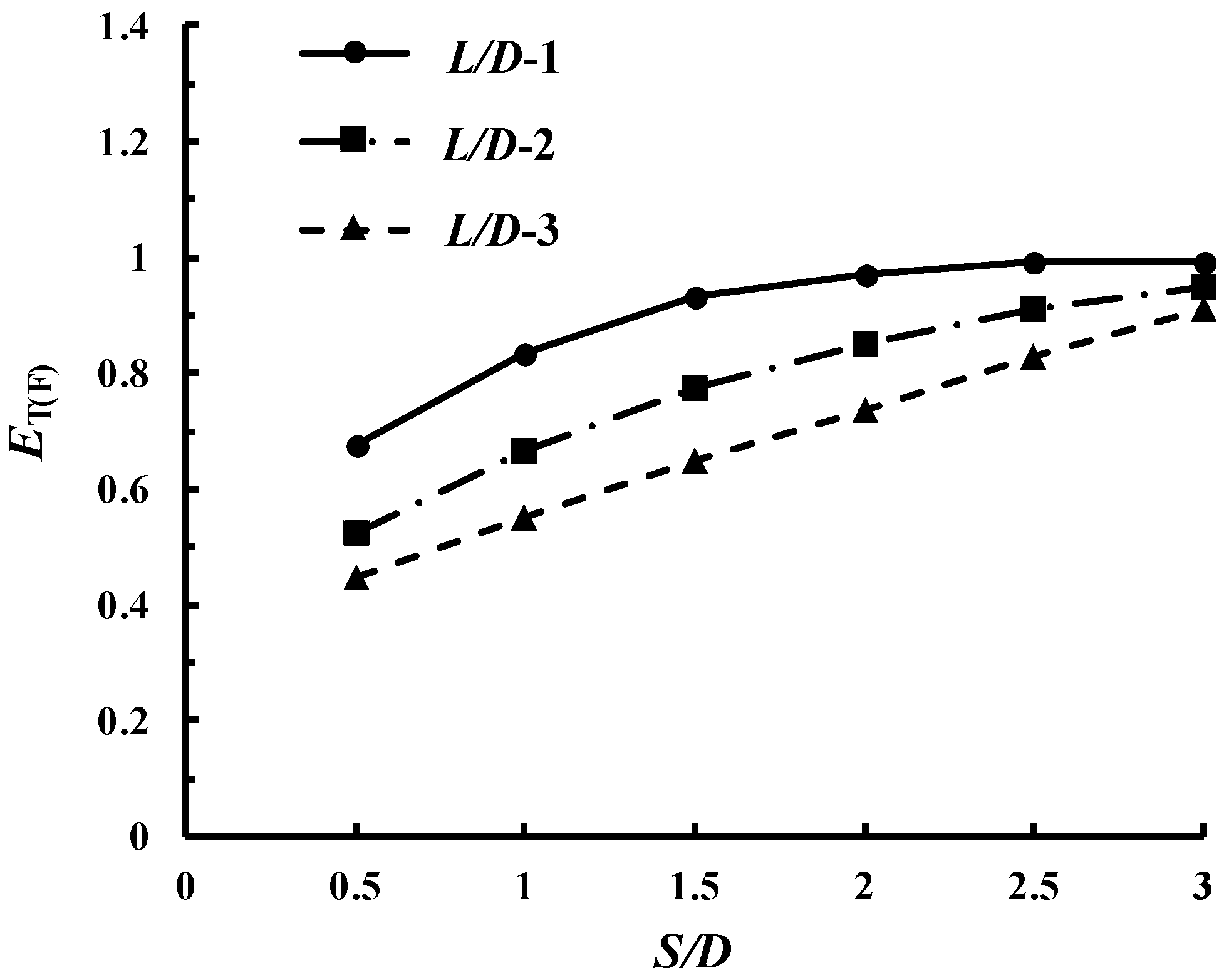
At S/D ratios ≤ 2, the EV varies from 0.96 to 1. At an S/D ratio ≥ 2, the EV is 1. The bending capacity can be obtained by multiplying the moment dimensionless load NM(S) of the single-barreled suction pile foundation with the pile group effect coefficient EM. The torsional carrying capacity can be calculated by multiplying the horizontal carrying capacity of the single-barreled suction pile foundation with a fixed rotational degree of freedom by the torque length.
(2)
The non-homogeneity of clay has little effect on the pile group effect coefficient of the carrying capacity of four-barreled suction pile foundations.
(3)
Under the combined action of horizontal and bending moment loads, the foundation carrying capacity envelope of the H-M load space shows obvious asymmetry. With the increase in S/D ratios, the bending moment carrying capacity increases proportionally. Due to the weakening of the pile group effect, the horizontal carrying capacity finally reaches a constant value at S/D = 2–3. Appropriate pile spacing should be selected to weaken the pile group effect in practical engineering design.
(4)
The size of the failure envelope of the foundation carrying capacity under the H-M load space of the four-barreled suction pile foundation decreases with the increase in the vertical load. When the vertical load increases from V = 0 to 0.75 Vult, the bending moment carrying capacity can be reduced by 59%. Considering the large weights of subsea oil platforms, it is necessary to pay attention to the vertical load in their design and construction.

Author Contributions

Conceptualization, Z.Q. and Y.W.; methodology, Z.Q.; software, Z.Q.; validation, T.W., C.W. and Y.W.; formal analysis, Z.Q.; investigation, F.W.; resources, J.W.; data curation, J.L.; writing—original draft preparation, Z.Q.; writing—review and editing, Z.Q.; visualization, Y.W.; supervision, T.W.; project administration, Z.Q.; funding acquisition, Y.W. All authors have read and agreed to the published version of the manuscript.

Funding

This research was funded by the National Natural Science Foundation of China (Grant No. 51879035).

Institutional Review Board Statement

Not applicable.

Informed Consent Statement

Not applicable.

Data Availability Statement

Not applicable.

Conflicts of Interest

The authors declare no conflict of interest.

References

  1. Achmus, M.; Kuo, Y.S.; Abdel-Rahman, K. Behavior of monopile foundations under cyclic lateral load. Comput. Geotech. 2009, 36, 725–735. [Google Scholar] [CrossRef]
  2. Houlsby, G.T.; Wroth, C.P. Calculation of Stresses on Shallow Penetrometers and Footings. In Seabed Mechanics; Springer: Berlin/Heidelberg, Germany, 1984; pp. 107–112. [Google Scholar]
  3. Butterfîeld, R.; Houlsby, G.T.; Gottardi, G. Standardized sign conventions and notation for generally loaded foundations. Geotechnique 1997, 47, 1051–1054. [Google Scholar] [CrossRef]
  4. Hu, Y.; Randolph, M.F.; Watson, P.G. Bearing response of skirted foundation on nonhomogeneous soil. J. Geotech. Geoenviron. Eng. 1999, 125, 924–935. [Google Scholar] [CrossRef]
  5. Wang, H.; Cheng, X. Undrained bearing capacity of suction caissons for offshore wind turbine foundations by numerical limit analysis. Mar. Geores. Geotechnol. 2015, 34, 252–264. [Google Scholar] [CrossRef]
  6. Houlsby, G.T.; Kelly, R.B. Field trials of suction caissons in clay for offshore wind turbine foundations. Geotechnique 2005, 55, 287–296. [Google Scholar] [CrossRef]
  7. Chen, W.; Randolph, M.F. Uplift capacity of suction caissons under sustained and cyclic loading in soft clay. J. Geotech. Geoenviron. Eng. 2007, 133, 1352–1363. [Google Scholar] [CrossRef]
  8. Yadav, S.K.; Ye, G.L.; Khalid, U.; Fukuda, M. Numerical and centrifugal physical modelling on soft clay improved with floating and fixed sand compaction piles. Comput. Geotech. 2019, 115, 103160. [Google Scholar] [CrossRef]
  9. Kim, S.R. Evaluation of vertical and horizontal bearing capacities of bucket foundations in clay. Ocean Eng. 2012, 52, 75–82. [Google Scholar]
  10. Vulpe, C. Design method for the undrained capacity of skirted circular foundations under combined loading: Effect of deformable soil plug. Geotechnique 2015, 65, 669–683. [Google Scholar] [CrossRef]
  11. Yadav, S.K.; Ye, G.L.; Xiong, Y.L.; Khalid, U. Unified numerical study of shallow foundation on structured soft clay under unconsolidated and consolidated-undrained loadings. Mar. Geores. Geotechnol. 2020, 38, 400–416. [Google Scholar] [CrossRef]
  12. Tanoli, A.Y.; Yan, B.; Xiong, Y.L.; Ye, G.L.; Khalid, U.; Xu, Z.H. Numerical analysis on zone-divided deep excavation in soft clays using a new small strain elasto—Plastic constitutive model. Undergr. Space 2022, 7, 19–36. [Google Scholar] [CrossRef]
  13. Gourvenec, S.; Jensen, K. Effect of embedment and spacing of cojoined skirted foundation systems on undrained limit states under general loading. Int. J. Geomech. 2009, 9, 267–279. [Google Scholar] [CrossRef]
  14. Kim, S.R.; Hung, L.C.; Oh, M. Group effect on bearing capacities of tripod bucket foundations in undrained clay. Ocean Eng. 2014, 79, 1–9. [Google Scholar] [CrossRef]
  15. Zhang, L.M.; Kong, L.G. Centrifuge modeling of torsional response of piles in sand. Can. Geotech. J. 2006, 43, 500–515. [Google Scholar] [CrossRef]
  16. Gourvenec, S.M.; Mana, D.S.K. Undrained vertical bearing capacity factors for shallow foundations. Geotechnique 2011, 1, 101–108. [Google Scholar] [CrossRef]
  17. Andersen, K.H.; Dyvik, R.; Schrøder, K.; Hansteen, O.E.; Bysveen, S. Field tests of anchors in clay II: Predictions and interpretation. J. Geotech. Eng. ASCE 1993, 119, 1532–1549. [Google Scholar] [CrossRef]
  18. Zhu, B.; Dai, J.L.; Kong, D.Q.; Feng, L.Y.; Chen, Y.M. Centrifuge modelling of uplift response of suction caisson groups in soft clay. Can. Geotech. J. 2020, 57, 1294–1303. [Google Scholar] [CrossRef]
  19. Stergiou, T.; Terzis, D.; Georgiadis, K. Undrained bearing capacity of tripod skirted foundations under eccentric loading. Geotechnik 2015, 38, 17–27. [Google Scholar] [CrossRef]
  20. Yun, G.; Bransby, M.F. The undrained vertical bearing capacity of skirted foundations. Soils Found. 2007, 47, 493–505. [Google Scholar] [CrossRef] [Green Version]
  21. Lai, Y.; Chen, C.; Zhu, B.; Dai, J.L.; Kong, D.Q. Numerical modelling on effect of loading rate on uplift behavior of suction caissons. Ocean Eng. 2022, 260, 112013. [Google Scholar] [CrossRef]
  22. Bhowmik, D.; Baidya, D.K.; Dasgupta, S.P. A numerical and experimental study of hollow steel pile in layered soil subjected to lateral dynamic loading. Soil Dyn. Earthq. Eng. 2013, 53, 119–129. [Google Scholar] [CrossRef]
  23. Sinha, A.; Hanna, A.M. 3D numerical model for piled raft foundation. Int. J. Geomech. 2017, 17, 04016055. [Google Scholar] [CrossRef]
  24. Achmus, M.; Akdag, C.T.; Thieken, K. Load-bearing behavior of suction bucket foundations in sand. Appl. Ocean Res. 2013, 43, 157–165. [Google Scholar] [CrossRef]
  25. Taiebat, H.A.; Carter, J.P. Numerical studies of the bearing capacity of shallow foundations on cohesive soil subjected to combined loading. Geotechnique 2000, 50, 409–418. [Google Scholar] [CrossRef] [Green Version]
  26. Houlsby, G.T.; Martin, C.M. Undrained bearing capacity factors for conical footings on clay. Geotechnique 2003, 53, 513–520. [Google Scholar] [CrossRef]
  27. Martin, C.M.; Hazell, E.C.J. Bearing Capacity of Parallel Strip Footings on Non-Homogeneous Clay. In Proceedings of the International Symposium on Frontiers in Offshore Geotechnics, Perth, Australia, 19–21 September 2005; pp. 427–433. [Google Scholar]
  28. Gourvenec, S.; Steinepreis, M. Undrained limit states of shallow foundations acting in consort. Int. J. Geomech. 2007, 7, 194–205. [Google Scholar] [CrossRef]
  29. Xiao, Z.; Tian, Y.; Gourvenec, S. A practical method to evaluate failure envelopes of shallow foundations considering soil strain softening and rate effects. Appl. Ocean Res. 2016, 59, 395–407. [Google Scholar] [CrossRef] [Green Version]
  30. Fan, Q.L.; Luan, M.T. Elasto-Plastic FEM Analyses of Large-Diameter Cylindrical Structure in Soft Ground Subjected to Wave Cyclic Loading. Slope Stability, Retaining Walls, and Foundations. In Proceedings of the 2009 GeoHunan International Conference, Changsha, China, 3–6 August 2009. [Google Scholar]
  31. Bransby, F.; Randolph, M. The effect of embedment depth on the undrained response of skirted foundations to combined loading. Soils Found. 1999, 39, 19–33. [Google Scholar] [CrossRef] [Green Version]
  32. Bandyopadhyay, S.; Sengupta, A.; Parulekar, Y.M. Behavior of a combined piled raft foundation in a multi-layered soil subjected to vertical loading. Geomech. Eng. 2020, 21, 379–390. [Google Scholar]
  33. Mansur, C.I.; Kaufman, R.I. Pile Tests, Low-Sill Structures, Old River, Louisiana. J. Soil Mech. Found. Div. 1956, 82, 1079. [Google Scholar] [CrossRef]
  34. Supachawarote, C.; Randolph, M.; Gourvenec, S. Inclined Pull-Out Capacity of Suction Caissons. In Proceedings of the Fourteenth International Offshore and Polar Engineering Conference, Toulon, France, 23–28 May 2004. [Google Scholar]
  35. Gourvenec, S. Effect of embedment on the undrained capacity of shallow foundations under general loading. Geotechnique 2008, 58, 177–185. [Google Scholar] [CrossRef]
Figure 1. Geometry of four-barreled suction pile foundation and definition of loads: (a) oblique upper view; (b) top view.
Processes 10 02459 g001
Figure 2. Element meshing: (a) typical 3D mesh view; (b) top view; (c) side view.
Processes 10 02459 g002
Figure 3. Comparison of load–displacement curves between two methods [14].
Processes 10 02459 g003
Figure 4. Tangent intersection method for determining carrying capacity.
Processes 10 02459 g004
Figure 5. Carrying capacity envelope by fixed displacement ratio method.
Processes 10 02459 g005
Figure 6. Vertical dimensionless load and group efficiency with L/D and S/D ratios: (a) vertical dimensionless load NV(F); (b) group efficiency EV(F).
Processes 10 02459 g006
Figure 7. Displacement contours under vertical loading: (a) S/D = 0.5; (b) S/D = 1; (c) S/D = 2.
Processes 10 02459 g007
Figure 8. Horizontal dimensionless load with L/D and S/D ratios.
Processes 10 02459 g008
Figure 9. Displacement contours under horizontal loading: (a) L/D = 1 (single-barreled); (b) L/D = 1 (four-barreled); (c) L/D = 2(four-barreled); (d) L/D = 3(four-barreled).
Processes 10 02459 g009aProcesses 10 02459 g009b
Figure 10. Moment dimensionless load and group efficiency with L/D and S/D ratios: (a) moment dimensionless load NM(F); (b) group efficiency EM(F).
Processes 10 02459 g010
Figure 11. Displacement contours under moment loading (S/D = 1): (a) L/D = 1; (b) L/D = 2; (c) L/D = 3.
Processes 10 02459 g011
Figure 12. Torsional dimensionless load with L/D and S/D ratios.
Processes 10 02459 g012
Figure 13. Displacement contours under torsional loading (S/D = 1): (a) L/D = 1; (b) L/D = 2; (c) L/D = 3.
Processes 10 02459 g013aProcesses 10 02459 g013b
Figure 14. Torsional group efficiency with L/D and S/D ratios.
Processes 10 02459 g014
Figure 15. Comparison of group efficiency factors at various kD/Sum ratios: (a) vertical efficiency, (b) moment efficiency and (c) torque efficiency.
Processes 10 02459 g015
Figure 16. Dimensionless H-M capacity envelopes under different L/D and S/D ratios: (a) L/D = 1, (b) L/D = 1.5 and (c) L/D = 2.
Processes 10 02459 g016
Figure 17. Dimensionless V-H-M capacity envelopes under different S/D ratios: (a) S/D = 1 (2D); (b) S/D = 1 (3D); (c) S/D = 3 (2D); and (d) S/D = 3 (3D).
Processes 10 02459 g017aProcesses 10 02459 g017b
Table 1. Summary of notation for loads and displacement.
VerticalHorizontalMomentTorque
Load at RPVHMT
Displacement at RPVh θ θ
Carrying capacityVultHultMultTult
Dimensionless loadNV = Vult/(ASuo)NH = Hult/(ASuo)NM = Mult/(ADSuo)NT = Tult/(ADSuo)
Group efficiencyEV = NV(F)/NV(S)EH = NH(F)/NH(S)EM = NM(F)/NM(S)ET = NT(F)/NH(S)
Table 2. Input values for analyzing the effect of non-homogeneity of soil.
L/DS/DK (kPa/m)Sum (kPa)kD/Sum
10.5–31.253.1254
20.5–31.256.252
Publisher’s Note: MDPI stays neutral with regard to jurisdictional claims in published maps and institutional affiliations.

