
Numerical Modelling and Simulation of Heat Transfer during Magnetic Moulding of Al/SiCp Metal Matrix Composites
Department of Mechanical Engineering, Sri Sivasubramaniya Nadar College of Engineering, Kalavakkam 603110, India
*
Author to whom correspondence should be addressed.
Processes 2022, 10(10), 2144; https://doi.org/10.3390/pr10102144
Submission received: 6 September 2022
/
Revised: 8 October 2022
/
Accepted: 12 October 2022
/
Published: 20 October 2022
(This article belongs to the Section Manufacturing Processes and Systems)
Abstract
:In traditional casting, sand is used as a mould material to carry heat away from the melt. However, sand has certain disadvantages, such as poor thermal conductivity, burning of binders, undesirable transition resulting in mould failure, and defects in the components. To overcome these limitations, magnetic moulding technology was introduced more than a few decades ago, but the process never achieved the required industrial developments to commercialise this technology. It is essential to reconsider and develop this technology further to use it as a regular production process. In this paper, processing of Al/SiCp composite using magnetic moulding technology is discussed. The heat transfer results of magnetic moulding process are simulated using COMSOL Multiphysics software and compared with the sand casting process. The temperature distribution, thermal conductivity, and phase change have been studied, finding that steel shots as mould materials show better heat transfer results when compared with sand. This better heat transfer led to a decrease in solidification time by 25%, which in turn improved the hardness (by 70%), impact toughness (by 4 times), and wear resistance (by 42%) of the Al/SiCp cast produced. These results very clearly illustrate the unique signature of the magnetic moulding process.
1. Introduction
Casting is the building block of all manufacturing processes, where the liquid metal is transformed into solids of different shapes and sizes. Although this method is the simplest manufacturing path, it involves various challenges that depend on the parameters such as melting, moulding, alloying, pouring, solidification, and finishing. All the above parameters need to be controlled simultaneously for a better cast. A sub-optimal choice of these parameters may lead to defects in the cast product. Amongst the above parameters, the mould material used in the casting process is profoundly influential. The mould and the casting always co-exist for a sufficiently long period at high temperature, and both significantly influence to the quality of the cast. Conventionally, silica sand is used as a mould material because of its wider availability, appropriate particle size distribution, and high melting point [1]. However, the use of silica sand has its own limitations [2]. Studies have shown that the phase transition from alpha quartz to beta quartz at 530 °C results in volumetric expansion of about 2.5% accompanied by length changes of the mould of around 1.5%, leading to mould failure and loss of accuracy [3]. Chromite sand, which has relatively low thermal expansion and good cooling power, can be used as the mould material to overcome the defects of silica sand. However, chromite sand produces castings with a poor surface finish. Other alternate mould materials used are olivine and zircon sand, but both have their own limitations, one of them being the high cost involved in processing those materials.
These disadvantages can be overcome by using steel shots as the mould material as a part of the magnetic moulding process. Magnetic moulding is a technique developed by Wittmoser wherein the magnetic field is developed by a coil surrounding the cast setup when excited by a direct current [4]. This induced magnetic field fixes the steel shots, which are ferromagnetic in nature. Due to the magnetic field, the steel shots are held together, increasing the contact area between them. As a result, its thermal conductivity increases, resulting in faster heat transfer from the molten melt to the edge of the setup walls. Heat transfer also occurs due to natural convection of air around the setup. This method is advantageous over conventional casting because of the better thermal conductivity of the steel shots over sand, resulting in a faster cooling rate and reduction in the solidification time of casting, with a decrease in production time. Studies by Desai and Heinen have shown that the use of metal mould reduces casting expenses by about 30% due to the shortening of the time required for forming the mould cavity [5]. Furthermore, magnetic moulding leads to improved mechanical properties through grain refinement. Gelfroy et al. proved that the mould cohesion induced by the magnetic field to prevent the deformation of the mould during casting contributes for better dimensional tolerances [6]. They also studied the mechanical and thermal behaviour of Aluminium Silicon Alloy cast processed using the magnetic moulding technique. They then compared the results with the result obtained from the cast of same material processed using the lost foam process. In addition, they developed a mathematical modelling based on Chvorinov’s rule to compute the solidification time of magnetic moulding and the lost foam process. It is known that solidification time is based on the thermal conductivity, density, and specific heat of the mould. Hence, by changing the mould material, the solidification time can either increase or decrease. Suganthkumar et al. estimated the theoretical strength of the mould based on the pattern of arrangement of the balls and verified it experimentally [7]. The magnetic moulding process seems to be one of the potential processes for replacing sand castings in many critical areas of applications. With this requirement, it is very much essential to study the process through simulation and by performing detailed experiments in order to translate this lab scale process to the industrial scale. Furthermore, the magnetic moulding process is environmentally friendly, and steel shots can be reused and recycled. Studies by Goni have also proven that the magnetic field has little impact on the health and safety of workers [8].
In this paper, parameters such as temperature distribution, thermal conductivity, and phase transition for Al/SiCp metal matrix composite are examined. In addition, these results are compared with a conventional sand casting material (olivine sand). The computer simulation was carried out using COMSOL Multiphysics software to extract the temperature profile at specified locations, which are compared with the experimental values later in this paper. Experiments were performed to show that the cast produced using the magnetic moulding technique under optimal conditions (as determined from simulation) has better properties—such as impact strength, wear resistance, and hardness—when compared to the cast produced using sand casting.
2. Experimental Validation Setup
2.1. Magnetic Moulding Setup
The cast setup consists of a cylindrical container made of stainless steel with 100 mm diameter and 150 mm height, with 4 mm thickness on the bottom and sides of the container, as shown in Figure 1. The container is then filled with steel shots of a particular diameter up to 50 mm from the bottom. From the works of Bates et al., it can be understood that Expendable Polystyrene (EPS) coated with Fuller’s earth is generally used for the lost foam process [9]. In the current work, EPS foam coated with Fuller’s earth is held at the centre, and the remaining steel shots are filled around it up to the top of the cylinder. The EPS foam used is cylindrical in shape with 30 mm diameter and 100 mm height. It is coated with Fuller’s earth, as the research work of Karimian et al. shows that the Fuller’s earth coating provides optimum permeability for the hot gases to escape [10]. A copper coil of standard wire gauge (SWG) 19 is wound along the circumference of the cylindrical container. The ends of the coil are connected to an AC-to-DC converter that has an inbuilt transformer for varying the supply voltage and current. The current supplied to the coil produces a magnetic field around the cast setup.
2.2. Material Modelling
The material to be cast in this experiment is Al/SiCp composite, consisting of Aluminium alloy Al-6063 matrix reinforced with silicon carbide particles of 3 µm. The reason for choosing aluminium as the cast material is its melting point of around 655 °C, which is below the Curie point temperature of the mould material steel shots (900 °C). If the melting point is above the Curie point temperature of the mould material, then the steel shot’s ferromagnetic behaviour is lost, leading to non-induction of the magnetic field by the copper coil [3]. Casting Al/SiCp composite by using the magnetic moulding process, where the melt is stirred before pouring it into the mould, has the following advantages: (a) according to Zhilong et al., the magnetic field induced helps in grain refinement of the cast [11], and (b) according to Sijo and Jayadevan, the stirring of the melt before pouring results in proper distribution and more wettability of SiC particles in the matrix, ultimately increasing the fracture toughness [12]. The magnetic moulding setup as shown in Figure 1 has been carefully chosen to be made up of grade 304 L stainless steel. The reason for choosing this material is that it has low relative permeability (compared to other grades of stainless steel) and, according to the British Stainless Steel Association, it allows the magnetic lines of force to pass through the walls of the setup, thus binding the steel shots. Otherwise, all the flux lines will remain contained within the walls of the setup, resulting in no magnetization of the steel shots. Harvey PD has shown that grade 410 stainless sheet has very high relative permeability [13], and Boyer and Galls have shown that very high relative permeability allows the magnetic flux lines to orient the steel shots accordingly [14]. Hence, the mould material steel shots have been chosen to be made of grade 410 stainless steel. The materials which were found to be suitable in the simulation are listed along with their properties in Table 1, with corresponding references.

Table 1.
Suitable materials and their properties.
| Properties | Al/SiCp | Grade 410 SS [15,16] | Olivine Sand | Grade 304 L SS [15,16] | Copper |
|---|---|---|---|---|---|
| Density (kg/m3) | 2770 | 7880 | 3150 | 8000 | 8960 |
| Thermal conductivity, K (W/m K) | 200 | 25 | 7.5 | 16.2 | 400 |
| Specific heat at constant pressure, Cp (J/kg K) | 775 | 460 | c.f Figure 2 | 500 | 385 |
| Relative permeability | 1 | 750 | - | 1.008 | 1 |
| Electrical conductivity | 1.11 × 10⁷ | 1.74 × 10⁷ | - | 1.37 × 10⁷ | 6 × 10⁷ |
| Porosity | - | 0.4804 | 0.440 | - | - |
The diameter of the steel shots was varied as a parameter to study the temperature distribution. These diameters are expressed in the form of porosity (Φ), given by
where V is the total volume occupied by the solid material and Vvoid is the volume occupied by the voids.
In this study, three different diameters (0.18, 0.6, and 1 mm) of steel shots were considered and their corresponding porosity estimated, under the assumption that the steel shots are distributed uniformly. Table 2 gives the porosity of the three differently sized steel shots.
2.3. Theoretical Formulation
Numerical simulation of the moulding process to predict the temperature involves multiple physical processes. The magnetic field, air gaps in the compacted steel, pattern material, steel box, and the surrounding air environment need to be considered for the simulation. Hence, COMSOL Multiphysics software was used in this study. In this section, the governing equations and the corresponding boundary conditions are discussed.
2.3.1. Magnetic Field
The equations defined in this section are used to compute the magnetic field and induced current distribution in and around the coil and the conductor. Maxwell’s equations are used to correlate Ampere’s Law with the constitutive equations, as it employs the magnetic vector potential as a dependant variable.
where is the electrical conductivity, H is the magnetic field strength, B is the magnetic flux density, Je is the current density in the coil, V is the velocity of the conductor, E is the electric field strength, and A is the magnetic vector potential. The magnetic flux density and the magnetic field strength are related by
where M is the intensity of magnetisation and = 4π10−7 H/m is the permeability of a vacuum. The externally generated current density is given by
where N is the number of turns in the coil and Icoil and Acoil are the current given to the coil and the cross-sectional area of the coil, respectively. Ampere’s law is written as
The magnetic vector potential and the magnetic flux are computed by solving Equations (2) and (9).
2.3.2. Heat Transfer
The heat transfer in the system is governed by the classical transient diffusion equation:
where q = , k is the thermal conductivity (W/mK), Q is the internal heat source (W/m3), is the density of the solid medium (kg/m3), Cp is the specific heat capacity of the solid medium (J/kg K), and T is the temperature (K).
2.3.3. Porous Media
Mould materials such as steel shots and sand used in this study are porous in nature, and the heat equation used is similar to Equation (10), with small changes corresponding to a porous matrix filled with a fluid. The governing equation for heat transfer through porous media is given by [17]
where
where and are the density of the fluid and porous medium, respectively; Cf,p and Cp,p are the specific heat capacity of the fluid and the porous medium, respectively; u is the fluid velocity (m/s); keff, ks, and kp are the effective thermal conductivity, the conductivity of the solid, and the conductivity of the porous medium, respectively; and Vs is the solid volume fraction.
2.3.4. Phase Change Medium
The phase change medium solves the heat equation for specifying the properties of a phase change material according to the apparent heat capacity formulation. The aluminium domain changes from a liquid to a solid state, for which the governing equation is given by
where is the coefficient of thermal expansion, which is given by
The boundary condition used here is convective cooling, where the air around the cast setup cools the surface by natural convection. According to Nield and Bejan, the following equation represents the heat transfer coefficient on the outer side walls of the vertical thin cylinder [18]:
where h is the heat transfer coefficient for thermal convection; D and H are the diameter and height of the vertical cylinder, respectively; Pr is the Prandtl number; Text is the external or ambient temperature; is the coefficient of viscosity of the fluid medium; g is the acceleration due to gravity; and is the thermal conductivity of the fluid medium. The electromagnetic heat source is coupled with the heat equation to obtain the following:
where Qe is the resistive heating due to electric current.
2.4. Testing and Characterization
Charpy impact testing was performed on the cast specimen, prepared according to the ASTM E23 standard (10 mm × 10 mm × 55 mm, V-notch with 2 mm depth) on a Charpy impact testing machine, as shown in Figure 3.
A dry wear test was conducted on a pin-on-disc machine, as shown in Figure 4, to understand the effect of steel shots on the wear rate of the sample.
Figure 4.
Pin-on-disc wear test machine. A Brinell hardness test was performed on the specimen. The cast samples were cut to a height of 50 mm from the top, as shown in Figure 5 (not to scale). The cut section surface was smoothed with emery sheet and cleaned. The hardness values were found using a steel ball indenter, with an applied load of 100 N.

Surface roughness measurements were also made for the cast produced using magnetic moulding and the sand casting setup.
3. Results and Discussion
For numerical simulation, we used COMSOL Multiphysics 5.3, as it provides an easy platform for solving coupled multiphysics (viz., electromagnetism and heat transfer). For numerical calculations, the following assumptions were made:
- The temperature distribution is uniform throughout the EPS foam domain where the molten aluminium is poured.
- The heat loss due to radiation around the cast setup is negligible.
- The thermal expansion of the cast being produced is very small and can be neglected in the heat transfer equation.
- Axisymmetric conditions apply for the whole magnetic moulding setup (the corresponding equations were used while solving the model in the commercial software COMSOL).
- The material is homogeneous and isotropic.
- The Fuller’s earth coating on the EPS pattern is very thin and can be neglected.
Using the geometric section feature available in COMSOL, the domain was constructed. Due to radial symmetry, an axisymmetric analysis was used. Figure 6 shows the geometry and different regions in the model. The material properties for the corresponding domains were imported into the material library. Then, the magnetic field module was used to define the SWG-19 multi turn coil with 500 turns and an electrical conductivity of 6 × 10⁷ S/m. A current of 5 A was passed through the coil for about 30 s to study the effect of current on the temperature distribution. A current of 5 A was chosen because it has been experimentally determined that 5 A is the optimum current for achieving better properties of the cast [19]. Following the definition of the magnetic field module, the heat transfer module was set up, where the aluminium domain was defined as the phase change medium with 360 kJ/kg as the latent heat of fusion and 933.47 K as the phase transition temperature; the steel shots domain was defined as a porous media with a porosity value of 0.6 mm (Table 2).
Ronald et al. studied the influence of steel shots on the properties of the cast and found that steel shots of 0.6 mm produced a cast with better mechanical properties when compared with 0.1 mm and 1 mm steel shots [20]. Hence, steel shots of 0.6 mm were chosen as the mould material for magnetic moulding in this study. The aluminium domain was given an initial temperature of 973 K, and the outer boundary was subjected to convective boundary conditions according to Equation (13). The heat transfer and magnetic field modules were then coupled using the multiphysics interface module. After coupling, the domain was discretized with non-overlapping regions called elements. A systematic mesh convergence study was conducted; the details of the mesh employed for this study are given in Table 3.
A similar procedure was adopted for the mould material olivine sand, with the following changes: the magnetic domain is not defined and hence no magnetic field is used for the mould material. Since olivine sand is also a porous medium, the porosity value must be given as input. Experiments by Leclaire and Umnova show that the porosity value of olivine sand is 0.444, so this value was given as input [21].
3.1. Experimental Results
In addition to the systematic numerical study, specimens of Al/SiCp were cast using the two techniques (viz., sand casting and magnetic moulding), and the following experiments were carried on the cast material made from sand casting and magnetic moulding to understand the properties.
The aluminium metal was melted to 700 °C, to which silicon carbide particles (10% by weight) were added and stirred in at around 300 RPM. A fluoride-based flux was added to prevent oxidation and also to improve the wettability. Once the melt was ready, it was poured into the EPS cylindrical pattern, which sublimed completely, leaving only the molten metal in the space occupied by the pattern. The Fuller’s earth around the pattern prevents direct contact between the mould and the molten material. In addition, this coating has the optimum permeability for the hot gases to escape. Steel shots of 0.6 mm diameter were selected as it is the optimum size for producing better properties of the cast [20]. The current induced in the coil was around 5 A for about 30 s, as beyond this time, overheating of the coil occurs, resulting in coil damage. This time is sufficient enough to compact the steel shots, increasing the heat transfer for phase transition. In addition, rapid heat transfer occurs only within this time to reach the equilibrium temperature between the surroundings and the cast. This casting experiment was also performed for the mould materials olivine sand, for which the input data were recorded and analysed.
The simulation results obtained have been plotted to understand the heat transfer behaviour of the mould materials used. Along with the heat transfer, a magnetic study was also performed. These observations primarily show the time-dependent behaviour of temperature, thermal conductivity, and phase change occurring at different time intervals. For the experimental perspective, a hardness test, dry wear test, and impact toughness test were conducted, and the properties of the cast material were studied.
3.2. Effect of Magnetic Field and Flux Lines
The current flowing through the coil produces a magnetic field out of the plane vector direction. The commercial software COMSOL was used to solve for the magnetic vector potential, from which one can compute whether the flux density induced is sufficient to compact the steel shots. Figure 7a shows the magnetic flux lines at the end of 10 s. From the figure, it is evident that the magnetic lines of force pass through the mould domain, orienting the steel shots along the line of force. The flux density can be computed from Equation (6) and is shown in Figure 7b for 0–60 s. For the current study, the whole mould domain was assumed to be concentrated at the centre point (30 mm from the x-axis and 104 mm from the y-axis) of the domain, as shown in Figure 6. From Figure 7b, one can see that for about 30 s while the current is flowing through the coil, the flux density in the domain is about 0.0024 Tesla.
3.3. Effect of Temperature at the Locations A, B, C and D
For ease of observation, a temperature study was conducted at four points on the top surface of the cast setup. These four locations are the points labelled as A, B, C, and D, as shown in Figure 6. The temperature variation at these four locations for magnetic moulding and sand casting for a time up to 60 s is shown in Figure 8, respectively.
From Figure 8a, it is evident that the temperature at the centre location (Figure 6) comes down to 370 K in 60 s for magnetic moulding, whereas in the case of sand casting, it decreases to 400 K at the same time. This shows that the steel shots conduct heat faster than the sand. Steel shots packed onto the shape of the mould are porous; they are filled with air gaps that are heated upon cooling of Al/SiCp. This in turn conducts the heat at a faster rate.
A similar trend can be observed at point B in Figure 8b. At the points C and D, it can be seen that the temperature of the mould increases at a faster rate for the magnetic moulding process (Figure 8c,d). This is because heat is conducted at a faster rate from the centre point towards the boundary in the case of magnetic moulding, when compared to the sand casting process.
The theoretical and experimentally observed cooling curve is shown in Figure 9. The solidification time for Al composite is almost the same theoretically and experimentally, and a very good agreement is seen until about 60 min. Figure 9 also shows the cooling curve for sand casting. Unlike the magnetic mould, the experimental cooling curve shows some difference when compared to the theoretical estimate. It can be seen that experimentally, the molten metal cools faster; this could be attributed to the moisture content present in the sand, which may conduct the heat faster. From Figure 9, it can be seen that the cooling curves are much faster for magnetic moulding than sand casting; this is due to the greater thermal conductivity of the steel shots.
3.4. Effect of Phase Transition of Al/SiCp
Phase transition from liquid to solid state is also an important factor in discerning the heat transfer properties of various mould materials. Solidification of molten metal starts from point B and ends at point A (Figure 6). Hence, the solidification of molten metal at point A indicates that the molten metal in the entire mould cavity has been solidified. Therefore, to study the effect of mould materials on the solidification time, finding the solidification time for point A is sufficient.
Figure 10 shows the phase transition of the aluminium domain with respect to time for various mould materials at point A. The transition is plotted along the y-axis as a dimensionless number within the range from 0 to 1, with 0 and 1 representing the solid state and liquid state, respectively. The diameter of the steel shots employed is 0.6 mm due to the better heat transfer characteristics of this size. It can be seen that the time taken for solidification of aluminium alloy from 700 °C for the mould materials steel shots and olivine sand is 3 and 4 s, respectively. This shows that the use of steel shots has reduced the solidification time by 25%. Faster solidification implies better cooling rate, indicating higher productivity and improved properties of the cast material.
3.5. Microstructure and Hardness Test
The literature states that there is a uniform distribution of SiC in the Al matrix in the case of sand casting [12]. Hence, microstructure was examined for magnetic moulding to ensure uniform distribution of the SiC reinforcement particles in the Al matrix. The SEM microstructure of the Al/SiCp cast using magnetic moulding techniques is shown in Figure 11. From the figure, it is clear that the reinforcement particles are uniformly distributed in the Al matrix in the case of the magnetic moulding process.
A Brinell hardness test was carried out on Al/SiCp samples cast from magnetic moulding and sand casting techniques. The cast samples were 100 mm in height; and for the hardness measurement, a specimen of height 50 mm was cut. The cut section surface was smoothed with emery sheets and prepared for the hardness test. The hardness values were found at specific locations on the periphery with a steel ball indenter of 1/16” diameter, using a dwell time of 10 s and an applied load of 100 N. The results of the hardness test are shown in Table 4. It can be seen that the cast produced using 0.6 mm steel shot mould has better properties than the cast made out of sand casting. The hardness of the cast processed using the sand casting technique was found to be 10 HB, whereas it is 17 HB for the magnetic moulding technique, representing a 70% increase.
3.6. Dry Wear Test
Using the pin-on-disc, a dry wear test was conducted to understand the effect of the mould material on the wear rate of the cast specimens. A cylindrical pin made of Al/SiCp with dimensions 10 mm diameter and 20 mm length was employed, and the disc material was EN8 (Figure 12). The experiment was carried out with a load of 10 N, a fixed sliding distance of 773 m, and a speed of 0.6 m/s. From the experiments, it was observed that the specific wear rate for the Al/SiCp cast using the magnetic moulding technique is 0.001269 mm3 N−1 m−1, whilst it is 0.0018121 mm3 N−1 m−1 for the sand cast specimen. This clearly indicates that the cast made by the magnetic moulding technique yields better wear resistance (increased by 42%).
3.7. Impact Toughness
For the impact study, the Charpy impact test was employed, for which the experiments were carried out at room temperature. The test piece was supported at the ends and a V-notch was introduced at the centre on the face that is opposite to the face where the pendulum strikes the test piece. For the cast specimen made from magnetic moulding, the average Charpy energy was found to be 28 J, while it was 7 J for the specimen made from sand casting. Hence, the impact toughness of the cast obtained using magnetic moulding is 4 times higher when compared to that of sand casting.
3.8. Surface Roughness
The surface roughness of the conventional sand cast and the magnetic moulding component was measured using a optical profiler with a cut-off length of 0.8 mm, as shown in Figure 13. Surface roughness measurements were made on the as-cast raw sample. The measured average height of the surface is around Ra = 3.736 μm for the sand casted and 4.035 μm for the magnetic moulded component. From Figure 13, it is also clear that the Rv value and Rp value are also higher for magnetic moulding.
4. Conclusions
In this study, the multiphysics computational domain was used to simulate the temperature distribution in the mould. The rate at which the temperature of the mould varies with time is a significant parameter that dictates the strength of the moulded components. The solidification time of the magnetic moulding was reduced by 25% in comparison with the sand casting, indicating that the components produced using the magnetic moulding process have better mechanical properties. Experimentally, it has also been proven that the application of the magnetic moulding technology results in an improvement of the mechanical properties of aluminium components considered in this study. Properties such as hardness, wear resistance, impact strength, and surface roughness of the moulded materials were studied for both sand and magnetic moulding. It was found that the magnetic moulded components showed better properties (increase in hardness by 70%, 4 times increase in impact toughness, 42% increase in wear resistance) when compared to the sand casted components. These encouraging results indicate the suitability of the magnetic moulding process as a suitable replacement for the sand casting process in the production environment.
Author Contributions
Conceptualization, A.P.C. and A.R.B.; methodology, A.P.C.; software, A.P.C. and S.R.; validation, A.P.C., S.R. and A.R.B.; formal analysis, A.P.C.; investigation, A.P.C.; resources, A.P.C. and A.R.B.; data curation, A.P.C. and S.R.; writing—original draft preparation, A.P.C. and S.R.; writing—review and editing, A.P.C. and A.R.B.; supervision, A.R.B.; project administration, A.P.C.; funding acquisition, A.R.B. All authors have read and agreed to the published version of the manuscript.
Funding
This research was funded by the Department of Science and Technologygrant number SB/FTP/ETA–67/2013.
Institutional Review Board Statement
Not applicable.
Informed Consent Statement
Not applicable.
Data Availability Statement
Not applicable.
Acknowledgments
The authors would like to acknowledge the Department of Mechanical Engineering, IIT Madras, for permission to use COMSOL software.
Conflicts of Interest
The authors declare no conflict of interest.
References
- Jain, S.; Ramesh Kumar, N.; Ishim, P. Challenges and Future Prospective of Alternative Materials to Silica Sand for Green Sand Mould Casting: A Review. Trans. Indian Inst. Met. 2021, 74, 2939–2952. [Google Scholar]
- Srinivasan, K.; Siddharth, C.S.K.; Kaarthic, L.V.A.; Thenarasu, M. Evaluation of mechanical properties, economic and environmental benefits of partially replacing silica sand with biomass ash for aluminium casting. Mater. Today Proc. 2018, 5, 483. [Google Scholar]
- Campbell, J. Complete Casting Handbook, 1st ed.; Elsevier: Amsterdam, The Netherlands, 2011. [Google Scholar]
- Wittmoser, A. The New Third Generation of Moulding Processes; AFS Transactions: Schaumburg, IL, USA, 1975. [Google Scholar]
- Desai, J.; Heinen, J. Permanent-Mould Casting. Number 3461–3463 in Encyclopedia of Material Science and Engineering; Elsevier: Amsterdam, The Netherlands, 1986. [Google Scholar]
- Geffroy, P.M.; Lakehal, M.; Goñi, J.; Beaugnon, E.; Heintz, J.M.; Silvain, J.F. Thermal and mechanical behavior of Al-Si alloy cast using magnetic moulding and lost foam processes. Metall. Mater. Trans. A 2006, 37, 441–447. [Google Scholar] [CrossRef]
- Senthilkumaran, S.; Boopathy, S.R.; Ramesh, A. Theoretical and experimental investigation of mould strength in magnetic moulding compacts. J. Mater. Process. Technol. 2008, 205, 235–242. [Google Scholar]
- Goni, J. The Innovative Casting Process for the Improvement of the Competitiveness and Working Conditions of the European Foundaries; Magnet Co-Operative Research Project Report; Fundación INASMET: San Sebastián, Spain, 2006. [Google Scholar]
- Bates, C.; Littleton, H.; Stroom, P. 64th World Foundary Congress; Foundary Technical Association: Paris, France, 2000. [Google Scholar]
- Karimian, M.; Ourdjini, A.; Idris, M.H.; Jafari, H. Effect of pattern coating thickness on the characteristics of lost foam Al-Si-Cu alloy casting. Trans. Nonferrous Met. Soc. China 2012, 22, 2092–2097. [Google Scholar] [CrossRef]
- Zhilong, Z.; Liu, Y.; Liu, L. Grain refinement induced by a pulsed magnetic field and synchronous solidification. Mater. Manuf. Process. 2011, 26, 1202–1206. [Google Scholar]
- Sijo, M.; Jayadevan, K. Analysis of stir cast aluminium silicon carbide metal matrix composite: A comprehensive review. Procedia Technol. 2016, 24, 379–385. [Google Scholar] [CrossRef] [Green Version]
- Harvey, P.D. (Ed.) Engineering Properties of Steels; Americal Society of Metals: Russell Twonship, OH, USA, 1982. [Google Scholar]
- Boyer, H.E.; Gall, T.L. (Eds.) Metals Handbook; American Society of Metals: Russell Twonship, OH, USA, 1985. [Google Scholar]
- Boyer, H.E.; Galls, T.L. Metals Handbook; Vol I: Properties and Selection: Irons, Steels and High performance alloys; ASM International: Almere, The Netherlands, 1985. [Google Scholar]
- Peckner, D.; Bernstein, I. (Eds.) Handbook of Stainless Steels; Mc Graw Hill Company: New York, NY, USA, 1977. [Google Scholar]
- Ingham, D.B.; Pop, I. Transport Phenomena in Porous Media; Elsevier: Amsterdam, The Netherlands, 1998. [Google Scholar]
- Nield, D.; Bejan, A. Convection in Porous Media; John Wiley & Sons: Hoboken, NJ, USA, 2013. [Google Scholar]
- Prakash, C.A.; Ronald, B.A.; Karthik, M.S. Effect of magnetic flux variation on the hardness of the magnetic moulded AlSiCp. In Proceedings of the National Symposium of Mechanical Engineering Research Scholars, NIT Warangal, Telangana, India, 7 October 2016. [Google Scholar]
- Anand Ronald, B.; Arun Prakash, C.; Suba Karthik, M. Influence of steel shots size on tensile properties of magnetic moulded MMC. Appl. Mech. Mater. 2016, 852, 118–122. [Google Scholar] [CrossRef]
- Leclaire, P.; Umnova, O.; Horoshenkov, K.V.; Maillet, L. Porosity measurement by comparison of air volumes. Rev. Sci. Instrum. 2003, 74, 1366–1370. [Google Scholar] [CrossRef]
Figure 1.
(a) Schematic diagram of the magnetic moulding setup showing the front and top view. (b) Actual magnetic moulding setup.
Figure 1.
(a) Schematic diagram of the magnetic moulding setup showing the front and top view. (b) Actual magnetic moulding setup.

Figure 2.
Variation of heat capacity with temperature for olivine sand at constant pressure.
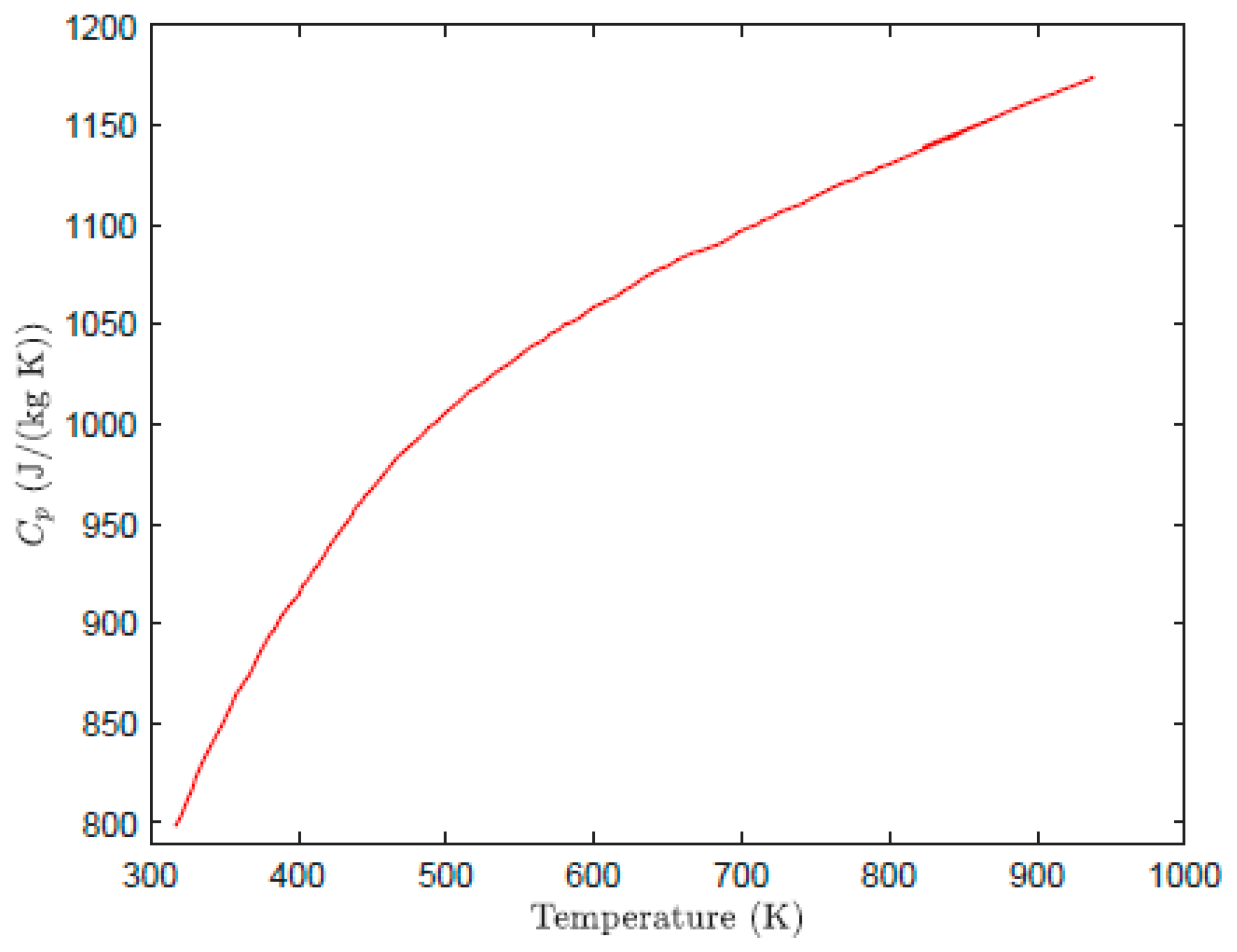
Figure 3.
Charpy impact test setup.
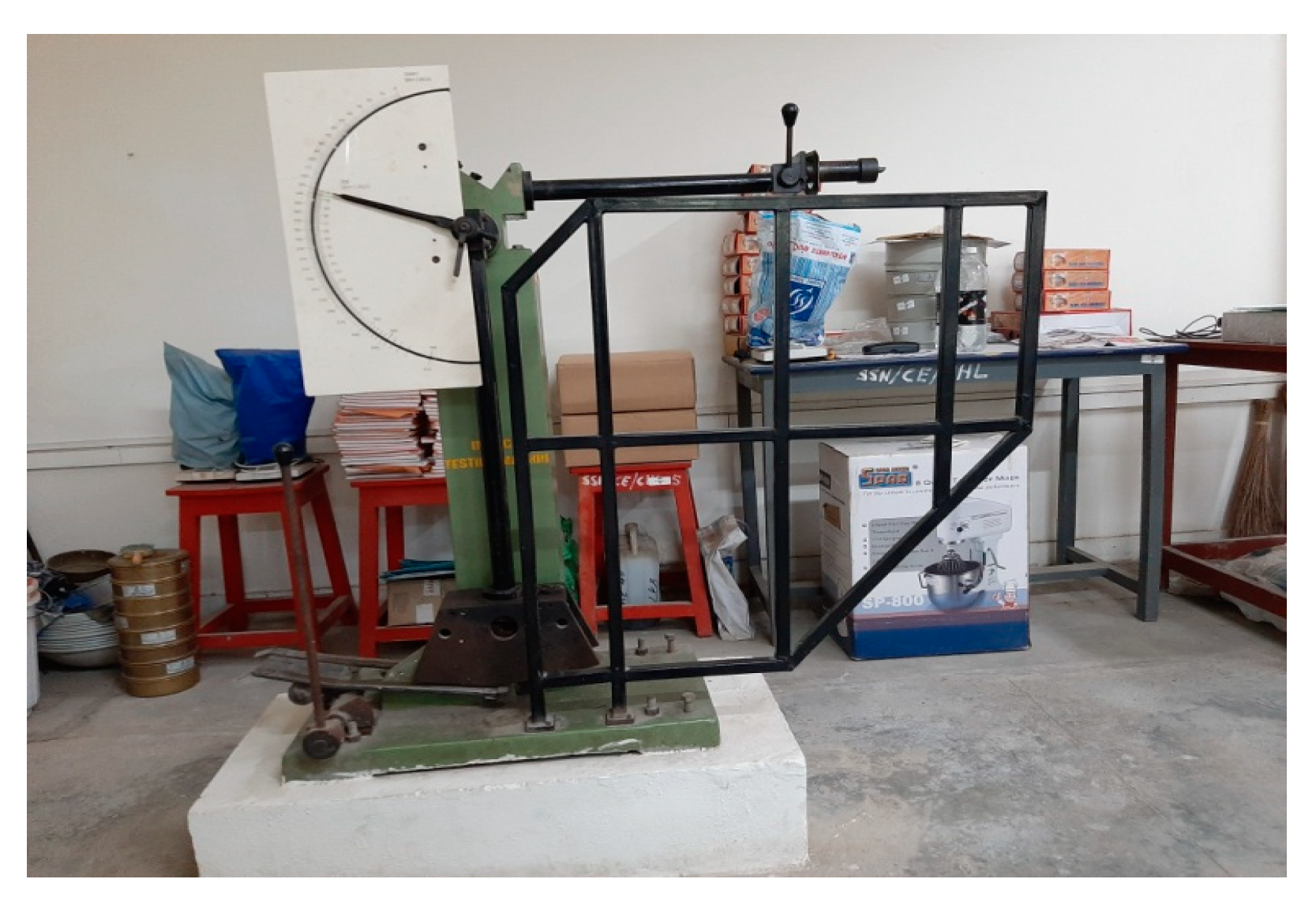
Figure 5.
Schematic representation of the locations where the hardness value was found.
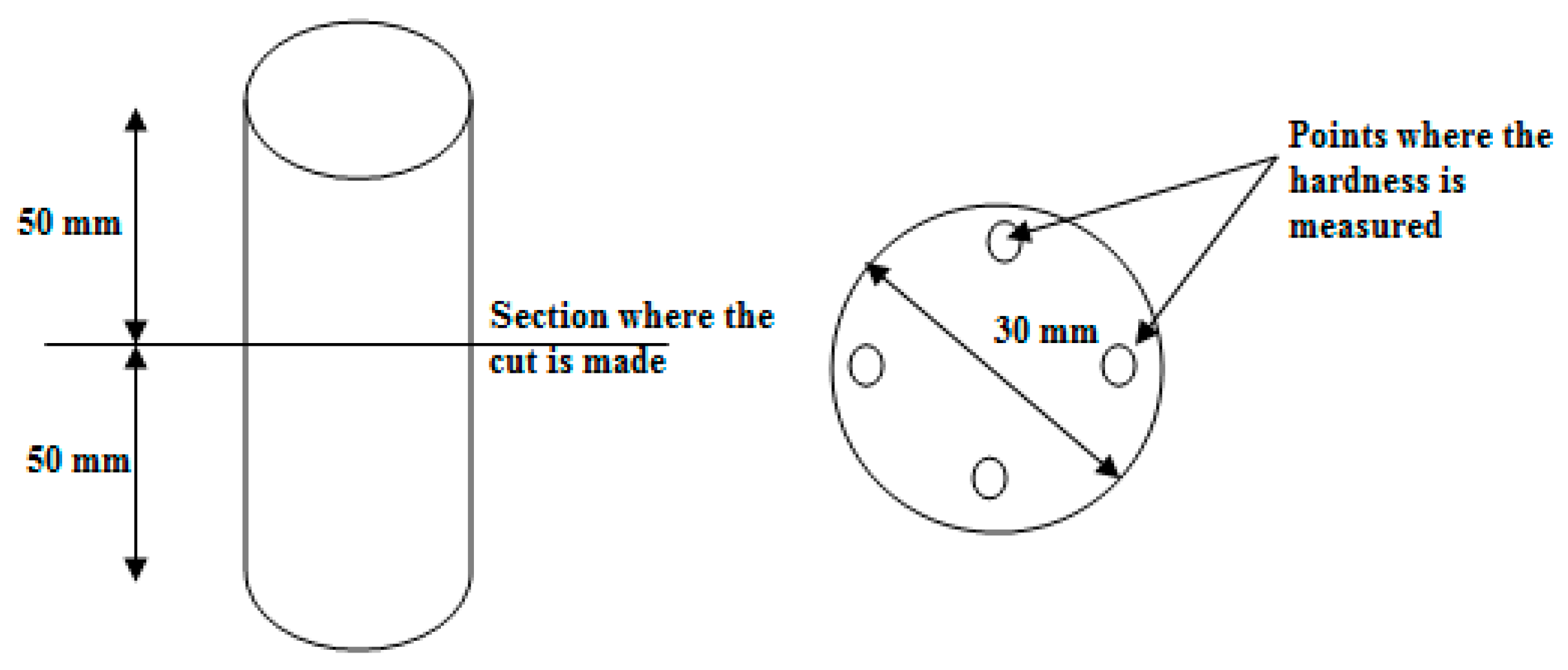
Figure 6.
Geometry and schematic of different regions of the model.
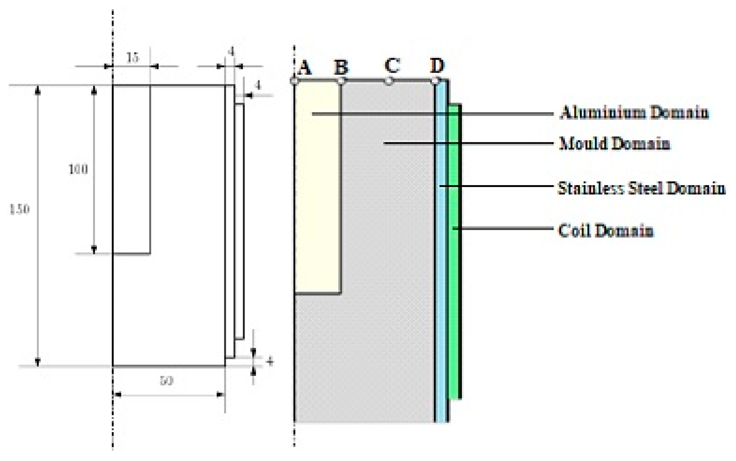
Figure 7.
Magnetic moulding process: (a) magnetic flux lines at the end of 10 s and (b) variation of magnitude flux with respect to time.
Figure 7.
Magnetic moulding process: (a) magnetic flux lines at the end of 10 s and (b) variation of magnitude flux with respect to time.
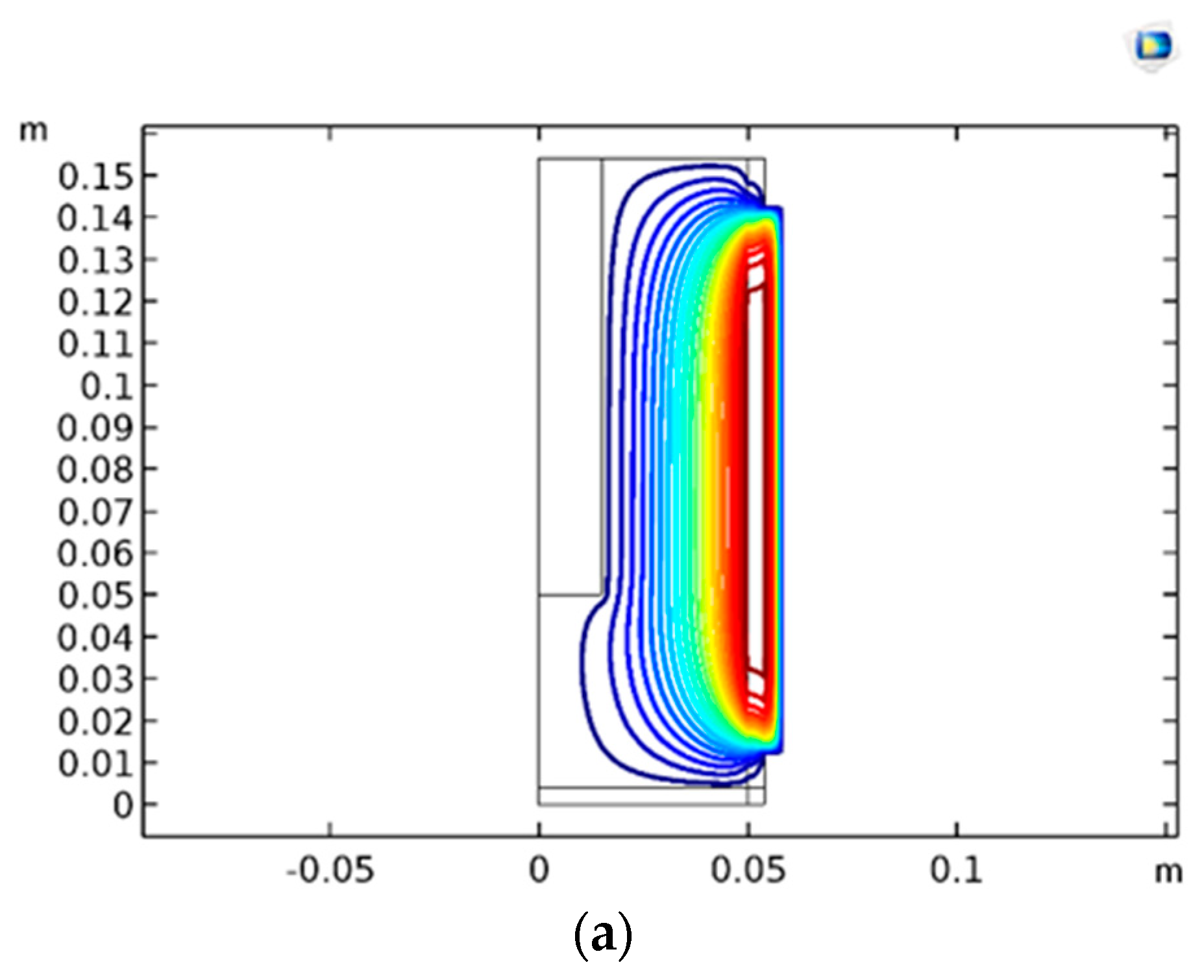
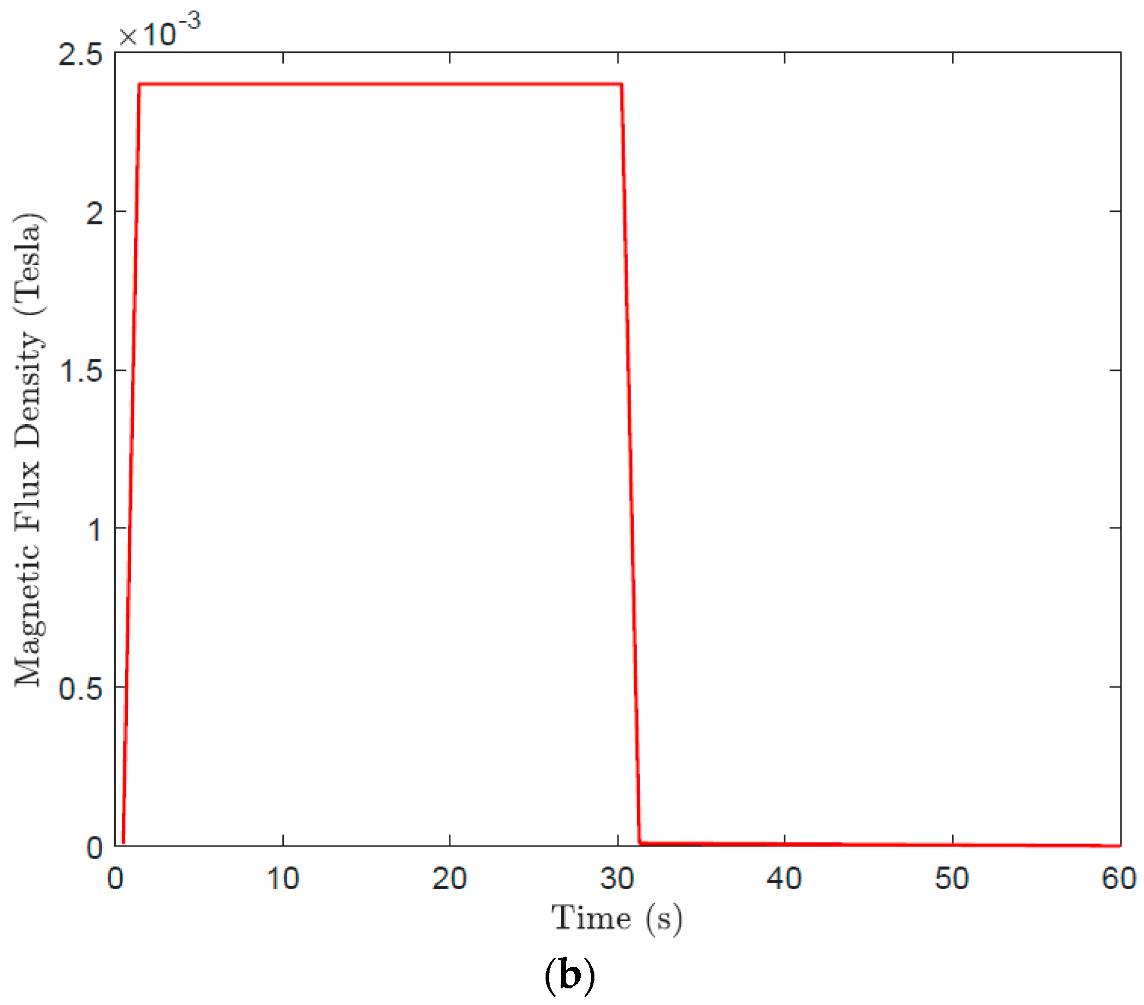
Figure 8.
Phase transition with respect to time from liquid to solid phase for different mould materials at different locations.
Figure 8.
Phase transition with respect to time from liquid to solid phase for different mould materials at different locations.
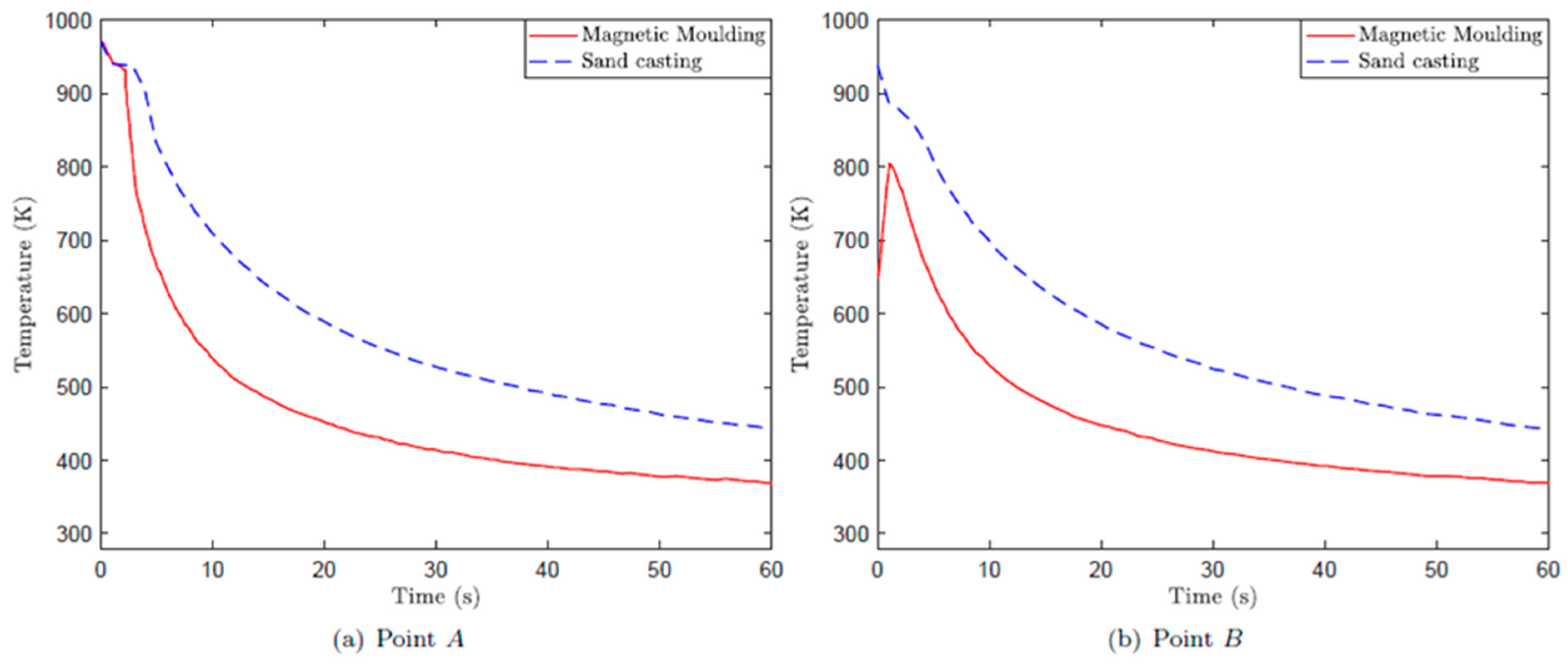

Figure 9.
Temperature as a function of time for magnetic moulding and sand casting based on numerical prediction and experimental observation.
Figure 9.
Temperature as a function of time for magnetic moulding and sand casting based on numerical prediction and experimental observation.
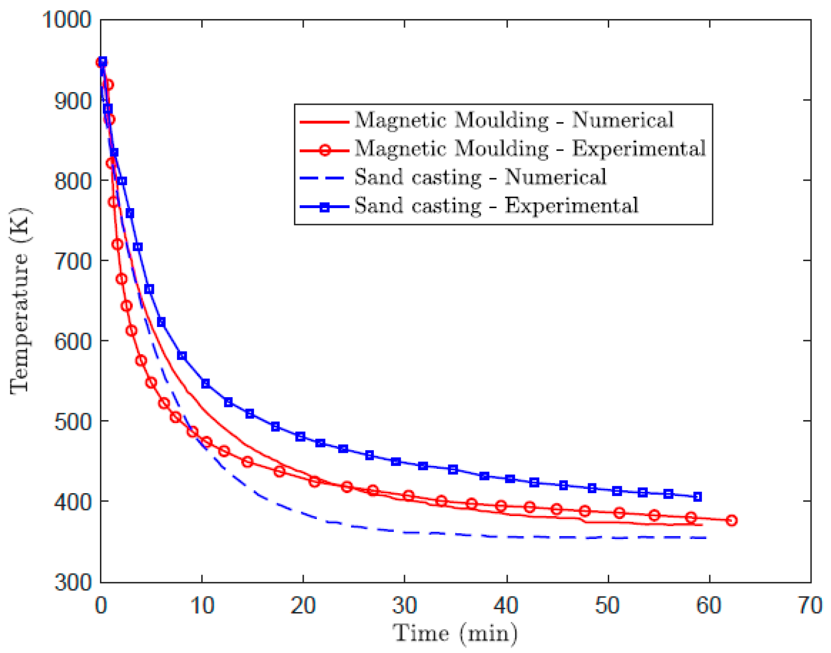
Figure 10.
Phase transition with respect to time from liquid to solid phase for different mould materials.
Figure 10.
Phase transition with respect to time from liquid to solid phase for different mould materials.
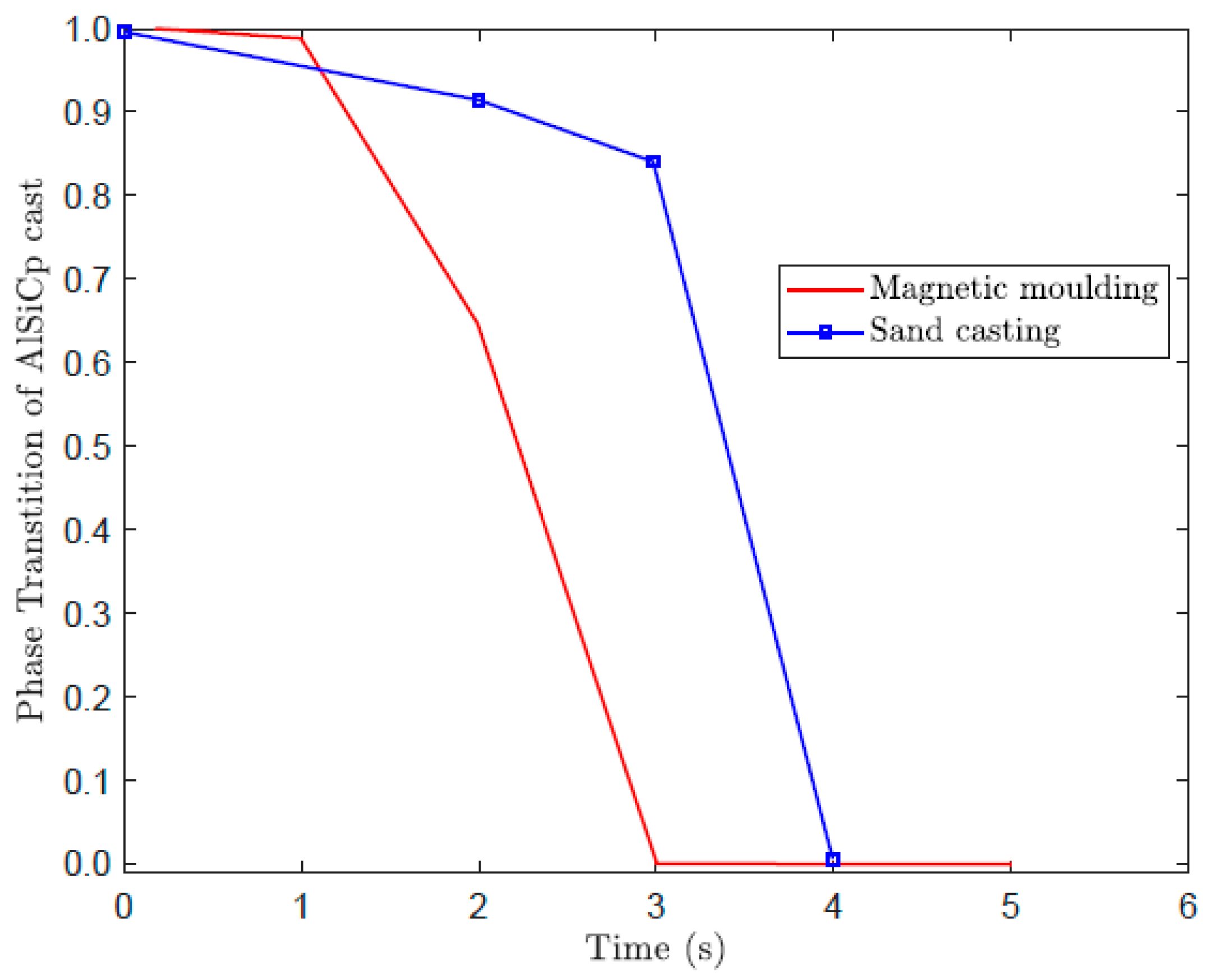
Figure 11.
SEM microstructure of Al/SiCp cast using magnetic moulding technique.
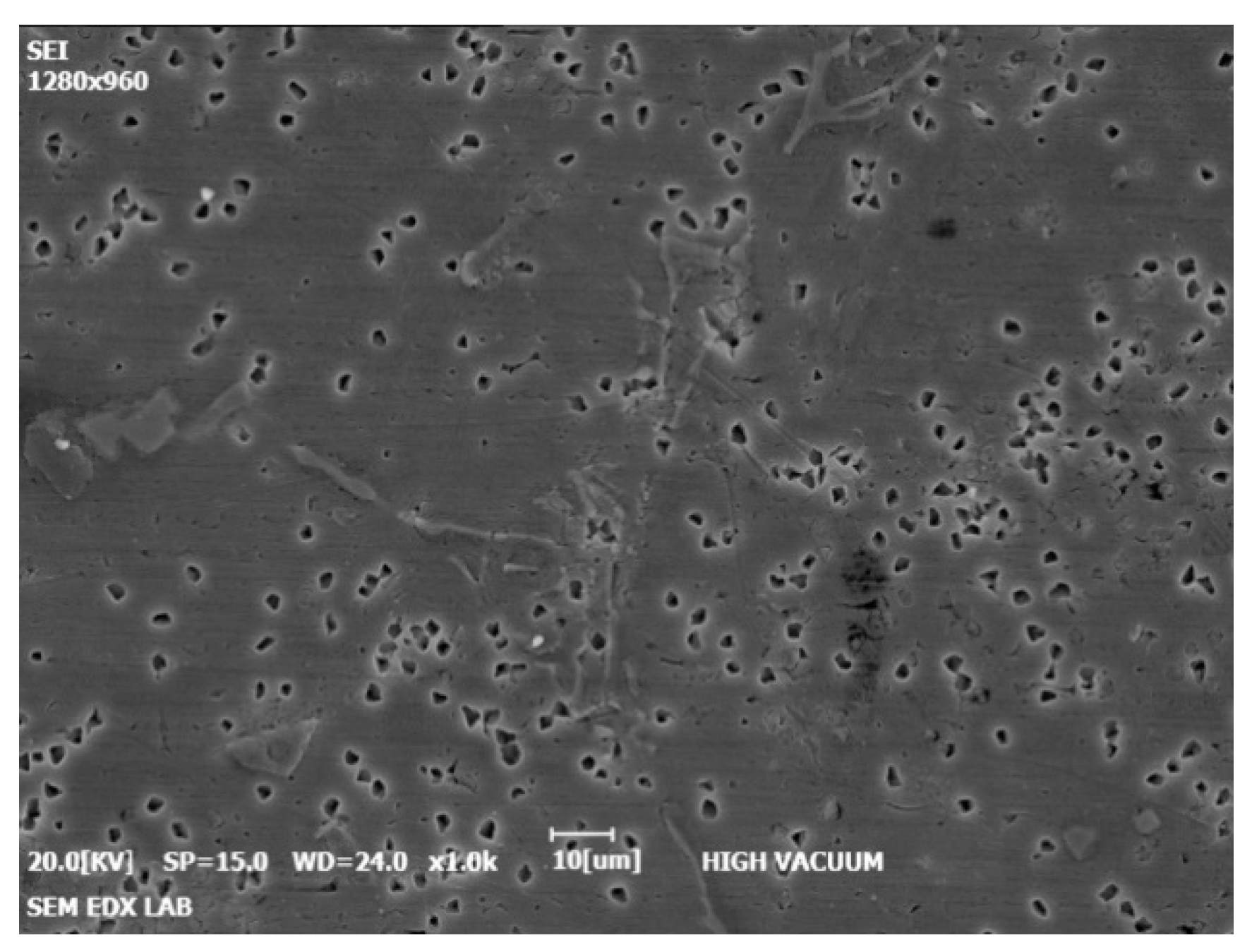
Figure 12.
Schematic representation of pin and disc.
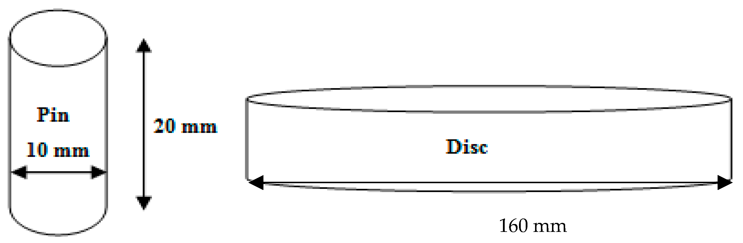
Figure 13.
2D surface roughness parameters.
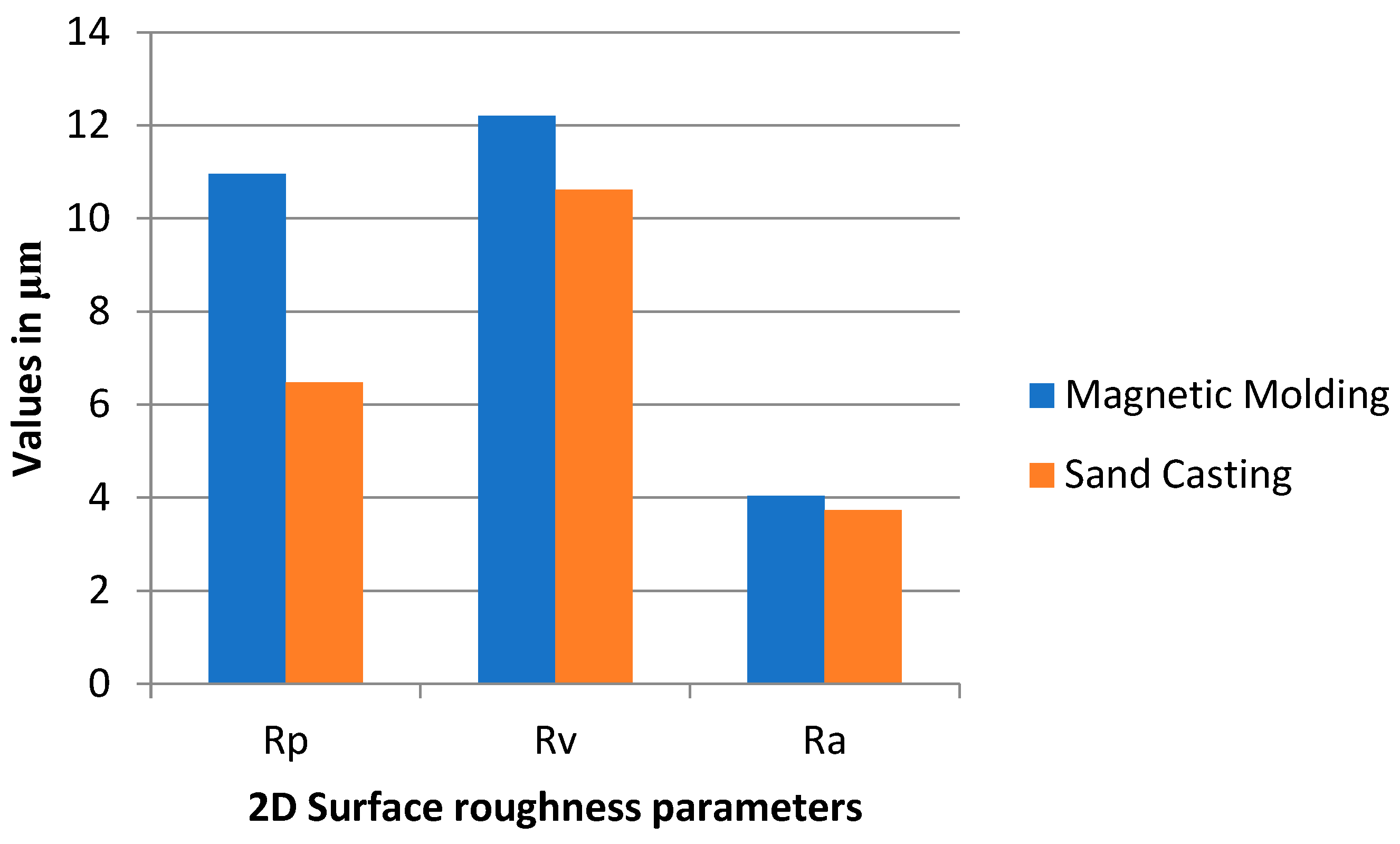
Table 2.
Porosity of steel shots.
| Diameter (mm) | V (mm3) | Porosity | Porosity in % |
|---|---|---|---|
| 0.18 | 0.5218 | 0.4782 | 47.82 |
| 0.60 | 0.5196 | 0.4804 | 48.04 |
| 1.00 | 0.5245 | 0.4755 | 47.55 |
Table 3.
Mesh statistics employed in this study.
| Description | Value |
|---|---|
| Minimum element quality | 0.7583 |
| Average element quality | 0.9847 |
| Triangular elements | 9277 |
| Edge elements | 490 |
| Vertex elements | 16 |
| Maximum element size | 0.00154 mm |
| Minimum element size | 3.08 × 10⁻⁶ mm |
| Curvature factor | 0.2 |
| Predefined size | Extremely fine |
Table 4.
Hardness value of the cast.
| S. No. | Process | Indentation Layer | Trial 1 | Trial 2 | Trial 3 | Trial 4 | Average (HB) |
|---|---|---|---|---|---|---|---|
| 1 | Sand Casting | Outer Layer | 9 | 11 | 9.8 | 10.2 | 10 |
| 2 | Magnetic Moulding | Outer Layer | 17 | 16 | 17 | 17 | 16.75 |
Publisher’s Note: MDPI stays neutral with regard to jurisdictional claims in published maps and institutional affiliations. |
© 2022 by the authors. Licensee MDPI, Basel, Switzerland. This article is an open access article distributed under the terms and conditions of the Creative Commons Attribution (CC BY) license (https://creativecommons.org/licenses/by/4.0/).
Share and Cite
MDPI and ACS Style
Chandran, A.P.; Ravimanalan, S.; Bennet, A.R. Numerical Modelling and Simulation of Heat Transfer during Magnetic Moulding of Al/SiCp Metal Matrix Composites. Processes 2022, 10, 2144. https://doi.org/10.3390/pr10102144
AMA Style
Chandran AP, Ravimanalan S, Bennet AR. Numerical Modelling and Simulation of Heat Transfer during Magnetic Moulding of Al/SiCp Metal Matrix Composites. Processes. 2022; 10(10):2144. https://doi.org/10.3390/pr10102144
Chicago/Turabian StyleChandran, Arun Prakash, Suraj Ravimanalan, and Anand Ronald Bennet. 2022. "Numerical Modelling and Simulation of Heat Transfer during Magnetic Moulding of Al/SiCp Metal Matrix Composites" Processes 10, no. 10: 2144. https://doi.org/10.3390/pr10102144
Note that from the first issue of 2016, this journal uses article numbers instead of page numbers. See further details here.