Article

Influence of Postprocessing on Wear Resistance of Aerospace Steel Parts Produced by Laser Powder Bed Fusion

by
Alexander S. Metel
1,
Sergey N. Grigoriev
1,
Tatiana V. Tarasova
1,
Anastasia A. Filatova
1,*,
Sergey K. Sundukov
2,
Marina A. Volosova
1,
Anna A. Okunkova
1,*,
Yury A. Melnik
1 and
Pavel A. Podrabinnik
1
1
Department of High-Efficiency Processing Technologies, Moscow State University of Technology «STANKIN», Vadkovsky per. 1, 127055 Moscow, Russia
2
Department “Technology of Construction Materials”, Moscow Automobile and Road Construction State Technical University (MADI), Leningradsky Prospect 64, 125319 Moscow, Russia
*
Authors to whom correspondence should be addressed.
Technologies 2020, 8(4), 73; https://doi.org/10.3390/technologies8040073
Submission received: 2 November 2020 / Revised: 19 November 2020 / Accepted: 26 November 2020 / Published: 2 December 2020
(This article belongs to the Special Issue 3D Printing Technologies II)

Abstract

:
The paper is devoted to the research of the effect of ultrasonic postprocessing—specifically, the effects of ultrasonic cavitation-abrasive finishing, ultrasonic plastic deformation, and vibration tumbling on surface quality, wear resistance, and the ability of real aircraft parts with complex geometries and with sizes less than and more than 100 mm to work in exploitation conditions. The parts were produced by laser powder bed fusion from two types of anticorrosion steels of austenitic and martensitic grades—20Kh13 (DIN 1.4021, X20Cr13, AISI 420) and 12Kh18N9T (DIN 1.4541, X10CrNiTi18-10, AISI 321). The finishing technologies based on mechanical action—plastic deformation, abrasive wear, and complex mechanolysis showed an effect on reducing the submicron surface roughness, removing the trapped powder granules from the manufactured functional surfaces and their wear resistance. The tests were completed by proving resistance of the produced parts to exploitation conditions—vibration fatigue and corrosion in salt fog. The roughness arithmetic mean deviation Ra was improved by 50–52% after cavitation-abrasive finishing, by 28–30% after ultrasonic plastic deformation, and by 65–70% after vibratory tumbling. The effect on wear resistance is correlated with the improved roughness. The effect of used techniques on resistance to abrasive wear was explained and grounded.

Graphical Abstract

1. Introduction

Laser additive manufacturing methods have been successfully developed for the last 30 years [1,2,3]; however, the parts’ final quality is often under the quality threshold required by the industry level [4,5,6,7,8] (anisotropy of properties, natural profile waviness, surface roughness parameter Ra higher than 6.3 µm, trapped unmelted granules, side effect) despite the evident advantages [9,10], especially concerning the production of the functional wear-resistant responsible products for more complex mechanisms for the needs of the transport, aircraft, and aerospace industries [11,12]. Another problem is the postprocessing of the obtained surfaces with a complex character and internal cavities that are mostly required for the parts produced by additive manufacturing [13,14,15]. Most of the postprocessing methods are oriented on the treatment of linear surfaces as mechanical abrasive [16,17,18] (the achievable roughness arithmetic mean deviation Ra is of 0.04 µm [19]), laser–plasma [14,20,21,22,23], ion–plasma (achievable average microroughness is up to 0.1–0.2 μm with a decrease in pulse width to 1.5 ns [24,25,26]), or electron beam [27,28,29] polishing that showed its effectiveness only on small flat areas with achievable microroughness more than 1 µm, ultrasonic plastic deformation, or their combination. Furthermore, the methods based on mechanical machining often leave cutting traces or traces of erosion such as those from cavitation-abrasive finishing that can dramatically influence the functional surfaces’ wear resistance. At the same time, the positive influence of local heating and remelting with the formation of a more fine-grained submicron structure while avoiding volumetric spreading and high quenching temperatures of the sample during laser–plasma, ion–plasma, and electron beam polishing, and while strengthening the surface and subsurface layers through plastic deformation, vibratory tumbling [30,31,32,33,34] for large-scale parts, and etching [35,36,37], in combination with reduced roughness can significantly improve the wear resistance of the surfaces in the friction pair [38,39] and ensure tight contact with detachable fasteners of parts when subsequent heat treatment reduces anisotropy of the exploitation properties [40,41,42,43,44]. Surface roughness parameters of additively manufactured parts are critical for the nuclear industry to provide smooth contact between rods and volumetric mesh structures [45,46] to ensure smooth surfaces of nozzles and dies [47,48].
It should be noted that there are not many works devoted to the postprocessing of the internal channels of the products produced by additive manufacturing, especially for anticorrosion structural steels of the austenite class, which are the most widespread in machine and aircraft building. The work of Breidenstein, B. [49] should be considered the most significant research on that topic; the authors researched the effect of face milling and/or deep rolling for surfaces produced by selective laser melting (laser powder bed fusion) from AISI H13 tool steel. The most significant effect was achieved for the samples with combined treatment—milling and subsequent rolling—by 24 times, from 28–37 µm down to 1.4 µm, when milling itself reduced the roughness by 3.2–6.3 µm and deep rolling only reduced it by 7–14 µm. At the same time, the hardness of the tempered samples with various temperatures mode (200 °C, 400 °C, 600 °C) was stabilized for each mode at the level of ~700 HV instead of deviation from 590–950 HV by application of the developed postprocessing techniques. The residual stress was significantly improved by deep rolling application that was especially noticeable for the low-tempering mode of 200 °C. Our own research showed the effectiveness of low tempering of 240 °C for additively manufactured parts from austenite steels; it improved physical and mechanical properties, including surface resistance to abrasive wear in comparison with the samples obtained by traditional casting and quenching, by at least more than two times [41]. Crayford, A.P. [50] reported on production of the functional part of 316 stainless steel with average submicron roughness of 12–26 µm that withstood the tests but demonstrated higher pressure drop across the air-path geometry and that should be reduced in further research studies by application of various postprocessing methods. Hunter, L.W. [51] reported on the inability to assemble functional parts due to the presence of trapped powder within a part made using powder bed fusion additive manufacturing that was not, up to now, researched enough by the scientific community, especially regarding the parts with complex surfaces and inner channels. By the opinion of the authors, the problem of trapped raw powder granules limits the application of additive manufacturing methods for complex geometries like heat exchangers and dies with conformal cooling channels. The samples obtained by laser and electron beam additive manufacturing were subjected to handheld ultrasonic polishing and proved their effectiveness for extremely elongated channels that could not be cleared by current industrial standards with grit blasting.
Based on the conducted investigation on the state of the art in the field of complex functional additively manufactured parts postprocessing, the following aim of the study was formulated—the research of the effect of three different postprocessing methods on the quality of the surfaces of a complex part for the aircraft industry and its influence of abrasive wear. The tasks of the study included:
  • research of the parts for which the operation steps by traditional production are complicated and involve extensive rebasing for a different type of equipment or complex assembly steps;
  • analyses of the surface quality of the parts after production in comparison with the requirements;
  • applying three different postprocessing methods to these parts based on their characteristics and requirements;
  • research of the obtained surfaces—topology and submicron roughness;
  • research on the influence of the obtained morphology on the resistance to abrasive wear in the friction pair.
Three different types of postprocessing methods based on mechanical interaction with the produced surface were chosen for investigation for laser additively manufactured parts (Figure 1): cavitation-abrasive finishing and ultrasonic plastic deformation for the small-scale parts (with an overall size of less than 100 mm) and vibration tumbling for the large-scale parts (with an overall size of more than 100 mm). All the chosen methods are based on the mechanical nature of the destruction, where the action of an abrasive agent, cavitation bubble, or hardened tip plays the role of a tool. The cavitation-abrasive finishing and vibration tumbling influence the surface quality volumetrically, but controlling the surface quality locally for the inner cavities remains difficult when most of the action is addressed to the outer surfaces. Despite the local hardening of surfaces by the effect of plastic deformation produced by the ceramic abrasive agent, the overuse of these finishing methods can dramatically influence their service life. Simultaneously, handheld implementation of ultrasonic plastic deformation (deep rolling or tipping) is more labor-intensive, but it allows more control over surface quality locally and achievement, in a pointwise manner, of finishing the most remote and deep places within the part.
The novelty of this research study is in the classification of volumetric and pointwise postprocessing methods for steel parts, and in the analyses of topology and submicron roughness of the parts after using the laser powder bed fusion method and after applying volumetric and pointwise postprocessing methods based on the mechanical action of plastic deformation by a tip and abrasive and complex nature of mechanolysis for small- and large-scale aircraft parts with complex geometries. The technologies are optimized, and the surface quality effect and the effect of the type of surface material destruction on resistance to abrasive wear are considered, determining surface effect influencing wear resistance since the chosen technology based on mechanical types of destruction affects the topology and submicron structure of the surface and subsurface layers differently, grounding the observed effects. The work’s practical significance is in obtaining new data and recommendations on the effects of various postprocessing methods (ultrasonic cavitation-abrasive finishing, surface plastic deformation, and vibration tumbling) on surface quality and wear resistance of real production parts used in the aerospace industry.

2. Materials and Methods

2.1. Research Object

A wide range of aircraft parts is manufactured from corrosion-resistant steels of the martensitic and austenitic classes because they provide the required performance properties. In this regard, the research on the postprocessing methods and modes was conducted using the examples of the real production parts: a locking washer of the quarter-turn locking mechanism made of 20Kh13 (analog of AISI 420, DIN 1.4021, X20Cr13 according to EN 10088-4) steel and a protective grille of the aircraft air intake made of corrosion-resistant 12Kh18N9T (analog of AISI 321, DIN 1.4541, X10CrNiTi18-10 according to EN 10088-1) steel (Figure 2).
The quarter-turn lock mechanism of the aircraft includes a pin, washer, and sleeve. Since the parts of the lock mechanism are small with a diameter of 11 mm and a height of 7 mm and complex-shaped (Figure 2a), its traditional production route is rather laborious and complicated; however, the application of the laser powder bed fusion method for its production simplifies the operation with no loss of the part exploitation properties. The material of the washer should be wear-resistant since there are friction surfaces between the two parts. Moreover, this material should differ in strength from the pin material by 20%, and there should not be a sticking effect between the parts; the strength of the lock pin is not less than 1300 MPa. The required hardness is not less than 42 HRC, the density is not less than 7.7 g·cm−3, and the roughness parameter Ra is less than 3.2 μm.
The air intake grille module is an element responsible for protecting the air intake duct and preventing foreign objects from entering it; the grille is an obstacle to the air intake to the engine with overall dimensions of 180 × 100 × 30 mm with the minimal thickness of the inclined wall of 0.3 mm (Figure 2b). The part should be produced following quality parameters: tensile strength should be not less than that of a standard semifinished product with a density of less than 7.9 g·cm−3 and roughness parameter Ra of less than 6.3 µm. The traditionally produced grille modules are characterized by significant labor intensity. Their manufacturing path includes such operational steps as cutting, bending, manual assembly of almost seventy parts, welding, soldering, etc. The research of the postprocessing methods’ effects on surface quality and wear resistance was conducted by grown samples of 20 × 20 × 20 mm for five pieces for each experimental set.

2.2. Production Technology

The direct laser manufacturing of the proposed complex parts from the powder takes their production to a new level [52,53,54] since it allows direct production of the parts from the powder layer-by-layer on a substrate in a vacuum chamber or in a chamber with a neutral atmosphere [55,56,57,58] by selective remelting of granules with a coherent and monochrome light beam [59,60]. Laser powder bed fusion was carried out on an EOS M280 industrial unit (EOS GmbH, Krailling, Germany) and an ALAM experimental setup (MSTU Stankin, Moscow, Russia) [61,62,63] equipped with the laser source of continuous radiation LK-200 (IPG LASER GMBH, Fryazino, Russia) with a wavelength of 1070 nm, a beam divergence of 0.2°, and maximum power of 200 W. Corrosion-resistant steel of the martensitic class, grade 20Kh13 (DIN 1.4021), and corrosion-resistant chromium-nickel steel of the austenitic class, grade12Kh18N9T (DIN 1.4541), were chosen for additive production. PR 20Kh13 (DIN 1.4021) steel powder with a fraction of 40 µm and PR 12Kh18N9T (DIN 1.4541) steel powder with a fraction of 80 µm (JSC POLEMA, Tula, Russia) are manufactured by dispersing molten metal with a jet of compressed gas [64,65]. The aircraft enterprise request determines the choice of steel grades. The chemical composition is presented in Table 1.
The powders were sifted with an analytical sieving machine AS200 basic (Retsch, Dusseldorf, Germany) with test sieves of 40 µm and 80 µm by ISO 3310-1. The sifted powders were predried in a vacuum oven VO400 (Memmert GmbH + Co. KG, Schwabach, Germany) to remove the excess air and provide a better powder density in each layer. The chosen processing factors at the EOS M280 and ALAM setups are presented in Table 2.
The quenching and tempering of the samples were produced in a chamber furnace CWF 12/23 with maximal temperature of 1200 °C and capacity of 23 L manufactured by Carbolite Gero (Hope Valley, UK). The comparison of the hardness and wear resistance test results were done on the casted samples in the state of delivery according to TU 14-1-377-72 produced by LLC “Chelyabinsk Forging-Mechanical Plant” (Chelyabinsk, Russia).

2.3. Surface Quality of the Samples

The reduction of the grown products’ submicron roughness was carried out using two methods: ultrasonic processing for the locking washer (small-scale part) and vibratory tumbling in water for the protective grille (large-scale part). Introduction of the ultrasonic vibration into a liquid brought cavitation bubble formation; with variable sound and radiation pressure, acoustic streams of various scales allow processing of outer and inner surfaces [30,31,32]. At the same time, ultrasonic plastic deformation is based on a complex physicochemical mechanism of the combined action of the high-intensity ultrasonic vibrations and stress implemented by the standard cutting equipment or handheld equipment [33,34,66,67]. Both ultrasonic processing types were carried out using a half-wave magnetostrictive oscillatory system powered by a UZG-1.6 generator (JSK “Ultra-resonance”, Yekaterinburg, Russia) with the vibration frequency in the range of 14–22 kHz that corresponded to the high-amplitude mode developing the cavitation region at the end surface of the radiator [68] and the vibration amplitude in the range of 12–30 μm.
For cavitation-abrasive finishing, the sample was placed in a radiator, on the bottom of which a layer of Elbor-R abrasive cubic boron nitride (β-BN) powder (JSC “SPC “Abrasives and Grinding”, Saint-Petersburg, Russia) of 2–4 mm thick was poured. The spatial orientation of the vibrating system is upside down: the emitter is placed in the center of the tank when the rest of the tank transmits oscillations (Figure 3a). The ultrasonic plastic deformation was carried out by manually pressing the horn tip of the transducer to the surface to be processed (Figure 3b).
The effectiveness of the chosen technologies was determined by analyses of the following roughness parameters that were evaluated for each experiment set according to EN ISO 4287:1997: arithmetic mean deviation (Ra), ten-point height (Rz), and maximum peak-to-valley height (Rtm). The maximum result in roughness parameters was achieved at the vibration frequency (f) of 20 kHz, the vibration amplitude (S) of 20 μm, and an abrasive layer thickness of 2 mm at 120 s processing. The achieved data were used in ultrasonic plastic deformation. The pressure of the tip was controlled manually. It should be noted that a further increase in forced frequency could dramatically influence the biological process in the human body—at the border of 30 kHz, cavitation arises with the formation of bubbles with a size of fractions of micrometers, which explains the lack of their visualization [69], when the frequencies of 41.5 and 39.3 kHz correspond to the self-oscillation frequencies of the samples made of 20Kh13 (DIN 1.4021) and 12Kh18N9T (DIN 1.4541), correspondingly [70].
A ZHM-80A vibratory tumbler (Shengxiang, Zhejiang, China) with a vibration frequency of 50 Hz, an engine speed of 1440 rpm, and a harmonic vibration amplitude of 6–7 mm was used for the vibratory tumbling. An SCT VFC filler with 10 × 10 prisms (CFT, Moscow, Russia) made of ceramics with 30% silicon was used. The samples’ roughness was controlled every hour to achieve the roughness arithmetic mean deviation Ra of 6.3 µm; then, it was controlled every 30 min of processing. The maximum effect of the abrasive action on roughness parameters was achieved at an operating time of 20.5 h. A further increase in operating time does not improve the roughness. It should be noted that vibratory tumbling should be conducted in a liquid medium (in our case, water) to bind airborne particles of abrasive and workpiece material. Dry vibratory tumbling is forbidden in numerous countries due to sanitary norms and rules of production, as inhaled dust can have dramatic health consequences, leading to various types of silicosis [66].

2.4. Characterization of the Samples

An Axio Observer D1m optical microscope (Carl Zeiss Microscopy GmbH, Kelsterbach, Germany) and a VEGA 3 LMH scanning electron microscope (Tescan Brno s.r.o., Brno, The Czech Republic) with magnification up to 1,000,000× controlled the microrelief of the obtained surfaces. The measurements of the geometric parameters of the grille modules were controlled using a ScopeCheck MB multisensor coordinate measuring machine for high-precision measurements of large workpieces (Werth Messtechnik GmbH, Giessen, Germany).
The density of the samples ρ was determined by hydrostatic weighing in distilled water using Archimedes’ principle and compared with the theoretical values using an XP504 laboratory balance (Mettler Toledo, Columbus, OH, USA) with an accuracy of 0.001 g/cm3 [67,68]. Gas porosity was estimated on panoramic images with an area of 4 mm2 (GOST 1583-93) using the Axio Observer D1m optical microscope; image processing including evaluation of the volume fraction of pores, the size distribution, and total porosity score was performed by a Thixomet Pro software (Thixomet, Saint-Petersburg, Russia). All sample cross-sections were polished up to 1.0 µm by an ATM Machine Tools equipment (ATM Machine Tools Ltd., Wokingham, UK).
The roughness was controlled by a high-precision profilometer, Hommel Tester T8000 (Jenoptik GmbH, Villingen-Schwenningen, Germany) and by a Dektak XT stylus profilometer (Bruker Nano, Inc., Billerica, MA, USA) with a vertical accuracy of 5 Å (0.5 nm) and a tip radius of 12.5 µm.
A Wilson Tukon 2500 Automated Knoop/Vickers Hardness Tester (Instron ITW Company, Norwood, MA, USA) was used to determine Vickers microhardness following GOST R ISO 6507-1-2007. A 574T Series Wilson Rockwell Hardness Tester (Instron ITW Company, Norwood, MA, USA) was used to determine Rockwell’s hardness following GOST 9013-59.
The wear resistance was determined using the method of water-jet wear by measuring the depth and width of the formed groove using a Calowear Instrument abrasion tester, which characterizes a surface’s resistance to abrasion (CSM Instruments, Peseux, Switzerland) (Figure 4). The tests were carried out with a friction rate of 594 rpm, a static load of 0.25 N, a ball diameter of 25.4 mm, test times of 3, 6, and 9 min, and a sample roughness arithmetic mean deviation Ra of 1.25 µm. An ODSCAD 6.2 measurement program (GFM LMI Technologies GmbH, Teltow, Germany) was used to investigate the diameter and depth of the resulting wells.
The experimental assessment of the strength of the blocks with the method of fatigue vibration tests was determined using a vibration test system, V830-440L shaker (BRUEL & KJAER VTS Ltd., Royston, Hertfordshire, UK). The tests of the external factors’ influence were carried out in a salt fog chamber SKB2000 A-SC (Gebr. Liebisch GmbH & Co. KG, Bielefeld, Germany) for combination tests with automatic ventilation. Tests were conducted according to GOST RV 20.39.304-98 and GOST RV 20.57.306-98.

3. Results

3.1. Density and Porosity

The measured density of the samples for laser additively manufactured parts and cast samples after quenching are presented in Table 3. The pore size of the produced samples does not exceed 0.01 mm (point 3) with the volume fraction of pores in the range of 0.05 ± 0.1%.

3.2. Roughness of the Samples

3.2.1. A Locking Washer

The roughness parameter Ra of a locking washer after additive manufacturing from 20Kh13 (DIN 1.4021) steel powder was 7.24 ± 0.19 μm, which is significantly higher than the required roughness arithmetic mean deviation Ra of 3.2 μm (Figure 5 and Figure 6). The obtained topology after various types of postprocessing was significantly improved. The presence of the trapped powder granules was not detected. The measured results of roughness before and after postprocessing are presented in Table 4.

3.2.2. A Grille Module

The roughness parameter Ra of a grille module after additive manufacturing from 12Kh18N9T (DIN 1.4541) steel powder varied in the range from 8.5 ± 0.21 to 14.1 ± 0.27 μm for the walls and for the grille itself and was higher than the required roughness arithmetic mean deviation Ra of 6.3 μm (Figure 7a,c). The measured roughness results are presented in Table 5; the obtained topology and profile are shown in Figure 7 b,d.

3.3. Hardness and Wear Resistance

The measured hardness of the samples produced by laser powder bed fusion before and after low tempering and cast samples after traditional quenching (austenitization) and low tempering (stabilization) are presented in Table 6 and Table 7. The measured microhardness of the samples correlated to the data obtained for Rockwell hardness.
Studies on abrasive wear of the laser additive manufactured parts after the various type of finishing are presented in Figure 8, Figure 9 and Figure 10. As can be seen, the obtained microroughness positively influences wear resistance of the functional surfaces and can not only improve the functionality of the produced parts in friction pairs and ensure tight contact with detachable fasteners of parts but also improve their service life.

3.4. Tests on Vibration Fatigue and Resistance to External Factors

The 12Kh18N9T (DIN 1.4541) samples were subjected to vibratory tumbling; they passed vibration fatigue tests and tests for resistance to external influencing factors. For vibration fatigue tests, the samples were installed on a table with the attached vibration sensors for load and state monitoring and exposed to pulsators to reproduce the working loads; an oscilloscope recorded deformations. The results showed that the produced samples withstood the load and external factors’ tests, which were similar to those in real flight conditions. The test cycle in a salt fog chamber showed no corrosion traces found on the observed samples’ surfaces.

4. Discussion

As it is known, due to high cooling rates obtained during laser powder bed fusion, the produced samples have a fine structure that corresponds and is equal to the processes obtained in cast samples by quenching in liquid [71,72,73,74,75] that are not available for other types of additive manufacturing based on particles’ adhesion and diffusion [47,48]. The density of the produced parts corresponds to the values for cast samples, and porosity corresponds to the highest requirements for the samples obtained from the powders. Laser powder bed fusion provides mechanical properties at the satisfactory level, or higher for cast samples [76,77,78,79,80].
The results of the study showed that the provided mechanical methods of finishing have a positive effect on submicron roughness; they allow reduction of the average roughness parameter by 1.5–3.5 times (Figure 5, Figure 6 and Figure 7c,d) and removal of the trapped powder granules from the additively produced surfaces (Figure 7a,b), which should allow a significant improvement of the functionality of the surfaces in the friction pairs and tight contact with detachable fasteners of parts. The effect of finishing is higher with less hardness of the steels that correspond to the cast, quenched, and tempered samples (Table 4, Table 5 and Table 6). Simultaneously, low tempering of 240 °C has almost no effect on the microhardness of laser additively manufactured parts compared to the well-known effect on cast and quenched parts.
It should be noted that obtained data on cavitation-abrasive finishing corresponds to the data obtained by other authors’ works in this research field in the quantitative values (Ra of 3.04 µm) [30,31,32] and estimated at the level required for the research object. Simultaneously, more profound cavitation erosion topology that is more related to the classic mechanochemical reactions discussed below was obtained. Ultrasonic plastic deformation showed impressive results combined with mechanical machining [49] compared to the results obtained in the current work by applying ultrasonic plastic deformation (roughness arithmetic mean deviation Ra of 5.02 µm), which exceed previously reported data for deformation rolling (Ra of 7–14 µm) and allow reduction of roughness peaks when waviness of the parts’ surfaces almost does not change. However, the application of only plastic deformation or rolling allows significant reduction of residual stresses and excludes the presence of any chips or abrasions [66]. Vibratory tumbling was underestimated during the last several decades, as can be seen by the absence of relevant data, but it remains effective for large-scale parts, allowing the reduction of the roughness parameter Ra to 2.5 µm, which is less than the required 6.3 µm. It can show significant roughness reduction when combined with other postprocessing methods based on the mechanical, electromechanical, and thermal natures of action [51].
The effect of the used technique has a different nature. The cavitation-abrasive finishing is based on complex erosion of metals that include action with an exciting water molecule that can dissociate along with radiation and dissipation of excess energy into heat (OH* + hv), mechanochemical reactions due to the mechanolysis of water on H and OH with the increased concentration of O2 (accumulation of the molecular O2, H2O2) (cavitation action) and abrasive wear [81,82,83]. The obtained topology pattern also has a complex character associated with the traces of cavitation erosion and abrasive action wells. The formed heat can positively influence the sublayer’s properties of the formed surface with the formation of a thin-grain structure that can improve the abrasion wear of the functional surface [68,84,85,86]. This effect can explain differences in the obtained data on wear tests, where the part subjected to cavitation-abrasive finishing showed the most significant resistance to wear (Figure 9). At the same time, overuse of cavitation-abrasive wear can lead to the embrittlement of formed surfaces due to the destructive character of mechanolysis. The resistance to abrasive wear was improved by 50–52% when the roughness was improved by 58–60%.
Ultrasonic plastic deformation is known for its positive influence on surface properties related to reducing internal stresses and mechanical hardening of the surface layer. However, the transducer tip’s pressure allows neither surface roughness reduction less than the achieved level nor changing the produced surfaces’ traditional layered pattern radically. Nonetheless, the ultrasonic plastic deformation effect has a character of an absolute value of a hyperbolic tangent of a reciprocal function of the applied load and coefficient of material plasticity—that is, with an increase in load, the average roughness achieved its maximum specularity, but a further increase does not provide any influence on surface roughness. This can be expressed as follows:
R a = R a tanh α E p
where R a is an average roughness after production, E is Young’s modulus, p is a stress of the transducer, and α is an empirical coefficient. Moreover, the test on abrasive wear showed that the achieved hardening effect is reduced over time, and the character of the resistance repeats the data obtained for the unfinished part, extending its service life in the friction pair by approximately 25% when the roughness was improved by 28–30%.
Vibration tumbling has an abrasive action on the produced surfaces when most technological dust is bound by water. It should be noted that dry vibratory tumbling is quite dangerous for the human respiratory system, and it is forbidden in some countries by sanitary production organizations’ requirements. Meanwhile, the abrasion action’s nature also has a slow hardening effect for subsurface layers archived by uniform impacts of abrasive particles detected by the abrasion wear test where the part’s resistance was improved by 51–52% when the roughness was improved by 65–70%. However, the vibration tumbling application can have a dramatic consequence for the service life of the parts that were controlled by an additional complex of tests.
It should be noted that the most outstanding results in surface quality for additively manufactured parts were obtained only by a combination of postprocessing methods of more rough and finishing technologies that allowed residual stress reduction and wear resistance improvement for the functional surfaces. It can be any form of mechanical machining or vibratory tumbling in combination with ultrasonic finishing or thermal polishing; the volumetric treatment should be combined with the pointwise method.
The vibration tests confirmed the ability of the modules to provide the specified strength and durability. The complex of the provided tests on resistance to external factors showed the adequacy of the obtained physical and mechanical properties of the grille modules produced by laser powder bed fusion from 12Kh18N9T (DIN 1.4541) steel to the operational conditions, which were close to the conditions of the real exploitation of the aircraft.

5. Conclusions

The research was conducted for two aircraft parts with complex geometries deemed labor-intensive for production by traditional manufacturing. The analyses of the surface qualities of the parts after laser powder bed fusion showed that the obtained surface quality was under the standard required for the functional parts level:
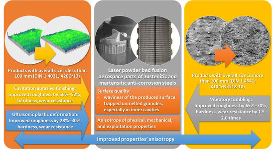
  • For the locking washer of 20Kh13 (DIN 1.4021) steel, Ra of 7.24 ± 0.19 μm, which is significantly higher than the required roughness Ra of 3.2 μm;
  • For the grille module of 12Kh18N9T (DIN 1.4541) steel, Ra of 8.5 ± 0.21 ÷ 14.1 ± 0.27 μm for the walls and for the grille itself instead of required Ra of 6.3 μm.
The produced surfaces contain the trapped powder granules that can reduce the parts’ exploitation properties in the friction pair and hampers the complex assembly processes for the detachable fasteners of parts in aircraft mechanisms. Three different postprocessing methods based on the mechanical nature of the destruction were applied to the chosen complex parts:
  • Cavitation-abrasive finishing and ultrasonic plastic deformation for the small-scale part with the overall size of less than 100 mm and
  • Vibration tumbling for the large-scale part with the overall size of more than 100 mm.
All these finishing methods have different mechanical action types that determine the topology of the obtained surfaces and, as it was shown, wear resistance of the functional surfaces. The most significant effect was obtained by cavitation-abrasive finishing; wear resistance was improved by 50–52% with the roughness reduction by 58–60%. At the same time, the embrittlement of the part related to the mechanolysis action was avoided. It is guessed that the subsurface layer’s hardening was achieved by complex action and local thermal effect of exciting water molecule dissociation and through plastic deformation by abrasive particles. The ultrasonic plastic deformation has a significant effect on the hardening of the surface and subsurface layer with a local pressure of the transducer tip; wear resistance was improved by approximately 25%, and the roughness was improved by 28–30%. The local plastic deformation of the surfaces produced by particles’ abrasive action during vibratory tumbling improved their wear resistance by 51–52% and the roughness by 65–70%.
The obtained new data on various finishing methods application for the aircraft have practical significance for the industry and can be used as a recommendation for choosing a finishing method to achieve the requirements on roughness and service life of the products during transferring from traditional manufacturing route to additive manufacturing and promote the transfer to the sixth technological paradigm.
To surpass the aerospace industry demands and to accelerate the switch to the next paradigm, additive manufactured parts should be subjected to complex technology of postprocessing, whereas trapped granules and natural waviness of the surface should be treated mechanically by one of the proposed methods or, where it is possible, premachined by traditional milling. At the same time, volumetric and local surface heat treatment is recommended to reduce residual stresses in volume and form a more wear-resistant fine-grained submicron structure by various plasma methods and coatings.

Author Contributions

Conceptualization, S.N.G. and M.A.V.; methodology, T.V.T. and S.K.S.; software, Y.A.M. and P.A.P.; validation, A.S.M. and Y.A.M.; formal analysis, A.S.M. and A.A.O.; investigation, A.A.F., T.V.T., and S.K.S.; resources, M.A.V. and P.A.P.; data curation, A.A.F. and Y.A.M.; writing—original draft preparation, A.A.F. and S.K.S.; writing—review and editing, T.V.T. and A.A.O.; visualization, A.A.O. and P.A.P.; supervision, S.N.G.; project administration, S.N.G. and M.A.V.; funding acquisition, A.S.M. All authors have read and agreed to the published version of the manuscript.

Funding

This research was funded by the Russian Science Foundation, grant number No. 20-19-00620.

Acknowledgments

The research was done at the Department of High-Efficiency Processing Technologies of MSTU Stankin.

Conflicts of Interest

The authors declare no conflict of interest. The funders had no role in the design of the study; in the collection, analyses, or interpretation of data; in the writing of the manuscript, or in the decision to publish the results.

References

  1. Terry, S.; Lu, H.; Fidan, I.; Zhang, Y.; Tantawi, K.; Guo, T.; Asiabanpour, B. The Influence of Smart Manufacturing towards Energy Conservation: A Review. Technologies 2020, 8, 31. [Google Scholar] [CrossRef]
  2. Acquesta, A.; Monetta, T. As-Built EBM and DMLS Ti-6Al-4V Parts: Topography–Corrosion Resistance Relationship in a Simulated Body Fluid. Metals 2020, 10, 1015. [Google Scholar] [CrossRef]
  3. Ghorbani, J.; Li, J.; Srivastava, A.K. Application of optimized laser surface re-melting process on selective laser melted 316L stainless steel inclined parts. J. Manuf. Processes 2020, 56, 726–734. [Google Scholar] [CrossRef]
  4. Salman, O.O.; Funk, A.; Waske, A.; Eckert, J.; Scudino, S. Additive Manufacturing of a 316L Steel Matrix Composite Reinforced with CeO2 Particles: Process Optimization by Adjusting the Laser Scanning Speed. Technologies 2018, 6, 25. [Google Scholar] [CrossRef] [Green Version]
  5. Doubenskaia, M.; Pavlov, M.; Grigoriev, S.; Tikhonova, E.; Smurov, I. Comprehensive Optical Monitoring of Selective Laser Melting. JLMN J. Laser Micro Nanoeng. 2012, 7, 236–243. [Google Scholar] [CrossRef]
  6. Manzhirov, A.V.; Murashkin, E.V.; Parshin, D.A. Modeling of Additive Manufacturing and Surface Growth Processes. In AIP Conference Proceedings, Proceedings of International Conference on Numerical Analysis and Applied Mathematics (ICNAAM), Rhodes, Greece, 13–18 September 2018; Simos, T., Tsitouras, C., Eds.; Amer Inst Physics: Melville, NY, USA, 2018; Volume 2116, p. 380011. [Google Scholar]
  7. Gorunov, A.I. Directional Crystallization of 316L Stainless Steel Specimens by Direct Laser Deposition. Inorg. Mater. 2019, 55, 1439–1444. [Google Scholar] [CrossRef]
  8. Kalashnikov, K.N.; Kalashnikova, A. Surface Morphology of Ti-alloy Samples Obtained by Electron Beam 3D-printing. In AIP Conference Proceedings, Proceedings of International Conference on Advanced Materials with Hierarchical Structure for New Technologies and Reliable Structures, Tomsk, Russia, 01–05 Oct 2019; Panin, V.E., Psakhie, S.G., Fomin, V.M., Eds.; Amer Inst Physics: Melville, NY, USA, 2019; Volume 2167, p. 020145. [Google Scholar]
  9. Willner, R.; Lender, S.; Ihl, A.; Wilsnack, C.; Gruber, S.; Brandao, A.; Pambaguian, L.; Riede, M.; Lopez, E.; Brueckner, F.; et al. Potential and challenges of additive manufacturing for topology optimized spacecraft structures. J. Laser Appl. 2020, 32, 032012. [Google Scholar] [CrossRef]
  10. Verna, E.; Genta, G.; Galetto, M.; Franceschini, F. Planning offline inspection strategies in low-volume manufacturing processes. Qual. Eng. 2020. [Google Scholar] [CrossRef]
  11. Saprykin, A.A.; Sharkeev, Y.P.; Saprykina, N.A.; Ibragimov, E.A. Selective Laser Melting of Magnesium. Key Eng. Mat. 2020, 839, 144–149. [Google Scholar] [CrossRef]
  12. Polozov, I.A.; Borisov, E.V.; Sufiiarov, V.S.; Popovich, A.A. Selective Laser Melting of Copper Alloy. Mater. Phy. Mech. 2020, 43, 65–71. [Google Scholar]
  13. Yadroitsev, I.; Bertrand, P.; Antonenkova, G.; Grigoriev, S.; Smurov, I. Use of track/layer morphology to develop functional parts by selectivelaser melting. J. Laser Appl. 2013, 25, 052003. [Google Scholar] [CrossRef]
  14. Lober, L.; Flache, C.; Petters, R.; Kuhn, U.; Eckert, J. Comparison of different post processing technologies for SLM generated 3161 steel parts. Rapid Prototyp. J. 2013, 19, 173–179. [Google Scholar] [CrossRef]
  15. Gatto, A.; Bassoli, E.; Denti, L.; Sola, A.; Tognoli, E.; Comin, A.; Porro, J.A.; Cordovilla, F.; Angulo, I.; Ocana, J.L. Effect of Three Different Finishing Processes on the Surface Morphology and Fatigue Life of A357.0 Parts Produced by Laser-Based Powder Bed Fusion. Adv. Eng. Mater. 2019, 21, 1801357. [Google Scholar] [CrossRef]
  16. Chen, Y.; Sun, H.; Li, Z.; Wu, Y.; Xiao, Y.; Chen, Z.; Zhong, S.; Wang, H. Strategy of Residual Stress Determination on Selective Laser Melted Al Alloy Using XRD. Materials 2020, 13, 451. [Google Scholar] [CrossRef] [Green Version]
  17. Wan, H.Y.; Luo, Y.W.; Zhang, B.; Song, Z.M.; Wang, L.Y.; Zhou, Z.J.; Li, C.P.; Chen, G.F.; Zhang, G.P. Effects of surface roughness and build thickness on fatigue properties of selective laser melted Inconel 718 at 650 degrees C. Int. J. Fatigue 2020, 137, 105654. [Google Scholar] [CrossRef]
  18. Jamshidi, P.; Aristizabal, M.; Kong, W.; Villapun, V.; Cox, S.C.; Grover, L.M.; Attallah, M.M. Selective Laser Melting of Ti-6Al-4V: The Impact of Post-processing on the Tensile, Fatigue and Biological Properties for Medical Implant Applications. Materials 2020, 13, 2813. [Google Scholar] [CrossRef]
  19. Cruz, N.; Martins, M.I.; Domingos Santos, J.; Gil Mur, J.; Tondela, J.P. Surface Comparison of Three Different Commercial Custom-Made Titanium Meshes Produced by SLM for Dental Applications. Materials 2020, 13, 2177. [Google Scholar] [CrossRef]
  20. Hollaender, A.; Cosemans, P. Surface technology for additive manufacturing. Plasma Process. Polym. 2020, 17, e1900155. [Google Scholar] [CrossRef] [Green Version]
  21. Volosova, M.A.; Grigoriev, S.N.; Ostrikov, E.A. Use of laser ablation for formation of discontinuous (discrete) wear-resistant coatings formed on solid carbide cutting tool by electron beam alloying and vacuum-arc deposition. Mech. Ind. 2016, 17, 720. [Google Scholar] [CrossRef]
  22. Metel, A.; Grigoriev, S.; Melnik, Y.; Panin, V.; Prudnikov, V. Cutting Tools Nitriding in Plasma Produced by a Fast Neutral Molecule Beam. Jpn. J. Appl. Phys. 2011, 50, 08JG04. [Google Scholar] [CrossRef]
  23. Danilov, I.; Hackert-Oschätzchen, M.; Zinecker, M.; Meichsner, G.; Edelmann, J.; Schubert, A. Process Understanding of Plasma Electrolytic Polishing through Multiphysics Simulation and Inline Metrology. Micromachines 2019, 10, 214. [Google Scholar] [CrossRef] [Green Version]
  24. Vereschaka, A.A.; Volosova, M.A.; Grigoriev, S.N.; Vereschaka, A.S. Development of wear-resistant complex for high-speed steel tool when using process of combined cathodic vacuum arc deposition. Proc. CIRP 2013, 9, 8–12. [Google Scholar] [CrossRef] [Green Version]
  25. Volosova, M.A.; Gurin, V.D. Influence of vacuum-plasma nitride coatings on contact processes and a mechanism of wear of working surfaces of high-speed steel cutting tool at interrupted cutting. J. Frict. Wear 2013, 34, 183–189. [Google Scholar] [CrossRef]
  26. Semenov, A.P.; Baldanov, B.B.; Ranzhurov, T.V. A Source of Nonequilibrium Argon Plasma Based on a Volume Gas Flow Discharge at Atmospheric Pressure. Instrum. Exp. Tech. 2020, 63, 284–287. [Google Scholar] [CrossRef]
  27. Jung, S.; Kang, E.; Park, J.; Kim, T.; Baek, S. A Study on Proposal of E-Beam Drilling Machining Criterion by Using on Vaporized Amplification Sheets in a High-Power Density Electron Beam. J. Nanosci. Nanotechnol. 2020, 20, 4231–4234. [Google Scholar] [CrossRef]
  28. Gavrilov, N.V.; Men’shakov, A.I. Effect of the electron beam and ion flux parameters on the rate of plasma nitriding of an austenitic stainless steel. Tech. Phys. 2012, 57, 399–404. [Google Scholar] [CrossRef]
  29. Fedorov, S.V.; Pavlov, M.D.; Okunkova, A.A. Effect of structural and phase transformations in alloyed subsurface layer of hard-alloy tools on their wear resistance during cutting of high-temperature alloys. J. Frict. Wear 2013, 34, 190–198. [Google Scholar] [CrossRef]
  30. Tan, K.L.; Yeo, S.H. Surface finishing on IN625 additively manufactured surfaces by combined ultrasonic cavitation and abrasion. Addit. Manuf. 2020, 31, 100938. [Google Scholar] [CrossRef]
  31. Wang, J.; Zhu, J.; Liew, P.J. Material Removal in Ultrasonic Abrasive Polishing of Additive Manufactured Components. Appl. Sci. 2019, 9, 5359. [Google Scholar] [CrossRef] [Green Version]
  32. Tan, K.L.; Yeo, S.H. Surface modification of additive manufactured components by ultrasonic cavitation abrasive finishing. Wear 2017, 378–379, 90–95. [Google Scholar] [CrossRef]
  33. Gou, J.; Wang, Z.; Hu, S.; Shen, J.; Tian, Y.; Zhao, G.; Chen, Y. Effects of ultrasonic peening treatment in three directions on grain refinement and anisotropy of cold metal transfer additive manufactured Ti-6Al-4V thin wall structure. J. Manuf. Process. 2020, 54, 148–157. [Google Scholar] [CrossRef]
  34. Zhou, C.; Jiang, F.; Xu, D.; Guo, C.H.; Zhao, C.Z.; Wang, Z.Q.; Wang, J.D. A calculation model to predict the impact stress field and depth of plastic deformation zone of additive manufactured parts in the process of ultrasonic impact treatment. J. Mater. Process. Technol. 2020, 280, 116599. [Google Scholar] [CrossRef]
  35. Bankowski, D.; Spadlo, S. Vibratory Machining Effect on the Properties of the Aaluminum Alloys Surface. Arch. Foundry Eng. 2017, 17, 19–24. [Google Scholar] [CrossRef] [Green Version]
  36. Dong, G.; Marleau-Finley, J.; Zhao, Y.F. Investigation of electrochemical post-processing procedure for Ti-6Al-4V lattice structure manufactured by direct metal laser sintering (DMLS). Int. J. Adv. Manuf. Tech. 2019, 104, 3401–3417. [Google Scholar] [CrossRef]
  37. Rotty, C.; Mandroyan, A.; Doche, M.-L.; Monney, S.; Hihn, J.Y.; Rouge, N. Electrochemical Superfinishing of Cast and ALM 316L Stainless Steels in Deep Eutectic Solvents: Surface Microroughness Evolution and Corrosion Resistance. J. Electrochem. Soc. 2019, 166, C468–C478. [Google Scholar] [CrossRef]
  38. Grigor’ev, S.N.; Fedorov, S.V.; Pavlov, M.D.; Okun’kova, A.A.; So, Y.M. Complex surface modification of carbide tool by Nb plus Hf plus Ti alloying followed by hardfacing (Ti plus Al)N. J. Frict. Wear 2013, 34, 14–18. [Google Scholar] [CrossRef]
  39. Volosova, M.A.; Grigor’ev, S.N.; Kuzin, V.V. Effect of titanium nitride coating on stress structural inhomogeneity in oxide-carbide ceramic. Part 4. Action of heat flow. Refract. Ind. Ceram. 2015, 56, 91–96. [Google Scholar] [CrossRef]
  40. Nath, S.D.; Irrinki, H.; Gupta, G.; Kearns, M.; Gulsoy, O.; Atre, S. Microstructure-property relationships of 420 stainless steel fabricated for by laser-powder bed fusion. Powder Technol. 2019, 343, 738–746. [Google Scholar] [CrossRef]
  41. Jamshidinia, M.; Sadek, A.; Wang, W.; Kelly, S. Additive Manufacturing of Steel Alloys Using Laser Powder-Bed Fusion. Adv. Mater. Process. 2015, 173, 20–24. [Google Scholar]
  42. Zhu, H.; Li, Y.; Li, B.; Zhang, Z.; Qiu, C. Effects of Low-Temperature Tempering on Microstructure and Properties of the Laser-Cladded AISI 420 Martensitic Stainless Steel Coating. Coatings 2018, 8, 451. [Google Scholar] [CrossRef] [Green Version]
  43. Khmyrov, R.; Grigoriev, S.; Okunkova, A.; Gusarov, A. On the possibility of selective laser melting of quartz glass. Phys. Procedia 2014, 56, 345–356. [Google Scholar] [CrossRef] [Green Version]
  44. Nowotny, S.; Tarasova, T.V.; Filatova, A.A.; Dolzhikova, E.Y. Methods for Characterizing Properties of Corrosion-Resistant Steel Powders Used for Powder Bed Fusion Processes. Mater. Sci. Forum 2016, 876, 1–7. [Google Scholar] [CrossRef]
  45. Gavrin, V.N.; Kozlova, Y.P.; Veretenkin, E.P.; Logachev, A.V.; Logacheva, A.I.; Lednev, I.S.; Okunkova, A.A. Reactor Target from Metal Chromium for “Pure” High-Intensive Artificial Neutrino Source. Phys. Part. Nucl. Lett. 2016, 13, 267–273. [Google Scholar] [CrossRef]
  46. Volosova, M.A.; Okunkova, A.A.; Povolotskiy, D.E.; Podrabinnik, P.A. Study of electrical discharge machining for the parts of nuclear industry usage. Mech. Ind. 2015, 16, 706. [Google Scholar] [CrossRef] [Green Version]
  47. Sova, A.; Okunkova, A.; Grigoriev, S.; Smurov, I. Velocity of the Particles Accelerated by a Cold Spray Micronozzle: Experimental Measurements and Numerical Simulation. J. Therm. Spray Tech. 2013, 22, 75–80. [Google Scholar] [CrossRef]
  48. Sova, A.; Doubenskaia, M.; Grigoriev, S.; Okunkova, A.; Smurov, I. Parameters of the Gas-Powder Supersonic Jet in Cold Spraying Using a Mask. J. Therm. Spray Technol. 2013, 22, 551–556. [Google Scholar] [CrossRef]
  49. Breidenstein, B.; Brenne, F.; Wu, L.; Niendorf, T.; Denkena, B. Effect of Post-Process Machining on Surface Properties of Additively Manufactured H13 Tool Steel. HTM J. Heat Treat. Mater. 2018, 73, 173–186. [Google Scholar] [CrossRef]
  50. Crayford, A.P.; Lacan, F.; Runyon, J.; Bowen, P.J.; Balwadkar, S.; Harper, J.; Pugh, D.G. Manufacture, characterization and stability limits of an am prefilming air-blast atomizer. In Proceedings of the ASME Turbo Expo: Turbomachinery Technical Conference and Exposition, Phoenix, AZ, USA, 17–21 June 2019; Amer Soc Mechanical Engineers: New York, NY, USA, 2019; Volume 4B. [Google Scholar]
  51. Hunter, L.W.; Brackett, D.; Brierley, N.; Yang, J.; Attallah, M.M. Assessment of trapped powder removal and inspection strategies for powder bed fusion techniques. Int. J. Adv. Manuf. Tech. 2020, 106, 4521–4532. [Google Scholar] [CrossRef] [Green Version]
  52. Cortina, M.; Arrizubieta, J.I.; Calleja, A.; Ukar, E.; Alberdi, A. Case Study to Illustrate the Potential of Conformal Cooling Channels for Hot Stamping Dies Manufactured Using Hybrid Process of Laser Metal Deposition (LMD) and Milling. Metals 2018, 8, 102. [Google Scholar] [CrossRef] [Green Version]
  53. Zhao, Y.; Li, F.; Chen, S.; Lu, Z.Y. Unit block-based process planning strategy of WAAM for complex shell-shaped component. Int. J. Adv. Manuf. Technol. 2019, 104, 3915–3927. [Google Scholar] [CrossRef]
  54. Han, P. Additive Design and Manufacturing of Jet Engine Parts. Engineering 2017, 3, 648–652. [Google Scholar] [CrossRef]
  55. Varela, J.; Merino, J.; Pickett, C.; Abu-Issa, A.; Arrieta, E.; Murr, L.E.; Wicker, R.B.; Ahlfors, M.; Godfrey, D.; Medina, F. Performance Characterization of Laser Powder Bed Fusion Fabricated Inconel 718 Treated with Experimental Hot Isostatic Processing Cycles. J. Manuf. Mater. Process. 2020, 4, 73. [Google Scholar] [CrossRef]
  56. Banoth, S.; Li, C.-W.; Hiratsuka, Y.; Kakehi, K. The Effect of Recrystallization on Creep Properties of Alloy IN939 Fabricated by Selective Laser Melting Process. Metals 2020, 10, 1016. [Google Scholar] [CrossRef]
  57. Teixeira, Ó.; Silva, F.J.G.; Ferreira, L.P.; Atzeni, E. A Review of Heat Treatments on Improving the Quality and Residual Stresses of the Ti–6Al–4V Parts Produced by Additive Manufacturing. Metals 2020, 10, 1006. [Google Scholar] [CrossRef]
  58. Bunnell, D.E.; Bourell, D.L.; Beaman, J.B.; Marcus, H.L. Fundamentals of liquid phase sintering during selective laser sintering. In Processing and Fabrication of Advanced Materials IV, Proceedings of Symposium on Processing and Fabrication of Advanced Materials IV, Cleveland, USA, 29 October–2 November 1995; Srivatsan, T.S., Moore, J.J., Eds.; Minerals, Metals & Materials Soc: Warrendale, PA, USA, 1996; pp. 17–26. [Google Scholar]
  59. Bourell, D.L.; Marcus, H.L.; Barlow, J.W.; Beaman, J.J. Selective Laser Sintering of Metals and Ceramics. Int. J. Powder Metall. 1992, 28, 369–381. [Google Scholar]
  60. Grigoriev, S.; Tarasova, T.; Gusarov, A.; Khmyrov, R.; Egorov, S. Possibilities of Manufacturing Products from Cermet Compositions Using Nanoscale Powders by Additive Manufacturing Methods. Materials 2019, 12, 3425. [Google Scholar] [CrossRef] [Green Version]
  61. Gusarov, A.V.; Grigoriev, S.N.; Volosova, M.A.; Melnik, Y.A.; Laskin, A.; Kotoban, D.V.; Okunkova, A.A. On productivity of laser additive manufacturing. J. Mater. Process. Technol. 2018, 261, 213–232. [Google Scholar] [CrossRef]
  62. Smurov, I.; Doubenskaia, M.; Grigoriev, S.; Nazarov, A. Optical Monitoring in Laser Cladding of Ti6Al4V. J. Therm. Spray Tech. 2012, 21, 1357–1362. [Google Scholar] [CrossRef]
  63. Metel, A.S.; Stebulyanin, M.M.; Fedorov, S.V.; Okunkova, A.A. Power Density Distribution for Laser Additive Manufacturing (SLM): Potential, Fundamentals and Advanced Applications. Technologies 2019, 7, 5. [Google Scholar] [CrossRef] [Green Version]
  64. Liu, Z.; Huang, C.; Gao, C.; Liu, R.; Chen, J.; Xiao, Z. Characterization Of Ti6al4v Powders Produced By Different Methods For Selective Electron Beam Melting. J. Min. Met. Sect. B Met. 2019, 55, 121–128. [Google Scholar] [CrossRef] [Green Version]
  65. Gao, C.F.; Xiao, Z.Y.; Zou, H.P.; Liu, Z.Q.; Chen, J.; Li, S.K.; Zhang, D.T. Characterization of spherical AlSi10Mg powder produced by double-nozzle gas atomization using different parameters. Trans. Nonferrous Met. Soc. China 2019, 29, 374–384. [Google Scholar] [CrossRef]
  66. Kropotkina, E.; Zykova, M.; Shein, A.; Kapustina, N. Application of roller burnishing technologies to improve the wear resistance of submerged pump parts made of powder alloys. Mech. Ind. 2018, 19, 705. [Google Scholar] [CrossRef]
  67. Naydenkin, E.; Mishin, I.; Khrustalyov, A.; Vorozhtsov, S.; Vorozhtsov, A. Influence of Combined Helical and Pass Rolling on Structure and Residual Porosity of an AA6082-0.2 wt% Al2O3 Composite Produced by Casting with Ultrasonic Processing. Metals 2017, 7, 544. [Google Scholar] [CrossRef] [Green Version]
  68. Badalyan, V.G.; Vorontsova, N.N.; Kazantsev, V.F.; Nazarov, A.V. Change of Copper Dislocational Structure after Action of Statical and Ultrasound Stresses. Fiz. Met. I Metalloved. 1982, 54, 1191–1193. [Google Scholar]
  69. Andreeva, T.A.; Berkovich, A.E.; Bykov, N.Y.; Kozyrev, S.V.; Lukin, A.Y. High-Intensity Focused Ultrasound: Heating and Destruction of Biological Tissue. Tech. Phys. 2020, 65, 1455–1466. [Google Scholar] [CrossRef]
  70. Grigoriev, S.N.; Metel, A.S.; Tarasova, T.V.; Filatova, A.A.; Sundukov, S.K.; Volosova, M.A.; Okunkova, A.A.; Melnik, Y.A.; Podrabinnik, P.A. Effect of cavitation erosion wear and vibration tumbling on additively manufactured parts’ surface quality. Metals 2020, 10, 1540. [Google Scholar] [CrossRef]
  71. Rando, R.J.; Vacek, P.M.; Glenn, R.E.; Kwon, C.W.; Parker, J.E. Retrospective Assessment of Respirable Quartz Exposure for a Silicosis Study of the Industrial Sand Industry. Ann. Work. Expo. Health 2018, 62, 1021–1032. [Google Scholar] [CrossRef]
  72. Hayu, R.; Sutanto, H.; Ismail, Z. Accurate density measurement of stainless steel weights by hydrostatic weighing system. Measurement 2019, 131, 120–124. [Google Scholar] [CrossRef]
  73. Firsov, K.N. Influence of Partial Wetting on the Results of Verification of Glass Hydrometers for Ethanol. Meas. Tech. 2017, 60, 92–95. [Google Scholar] [CrossRef]
  74. Rafieazad, M.; Ghaffari, M.; Nemani, A.V.; Nasiri, A. Microstructural evolution and mechanical properties of a low-carbon low-alloy steel produced by wire arc additive manufacturing. Int. J. Adv. Manuf. Technol. 2019, 105, 2121–2134. [Google Scholar] [CrossRef]
  75. Hung, C.H.; Sutton, A.; Li, Y.; Shen, Y.Y.; Tsai, H.L.; Leu, M.C. Enhanced mechanical properties for 304L stainless steel parts fabricated by laser-foil-printing additive manufacturing. J. Manuf. Process. 2019, 45, 438–446. [Google Scholar] [CrossRef]
  76. Grigoriev, S.N.; Metel, A.S.; Fedorov, S.V. Modification of the structure and properties of high-speed steel by combined vacuum-plasma treatment. Met. Sci. Heat Treat. 2012, 54, 8–12. [Google Scholar] [CrossRef]
  77. Tamadon, A.; Pons, D.J.; Clucas, D. AFM Characterization of Stir-Induced Micro-Flow Features within the AA6082-T6 BFSW Welds. Technologies 2019, 7, 80. [Google Scholar] [CrossRef] [Green Version]
  78. Garlea, E.; Choo, H.; Sluss, C.C.; Koehler, M.R.; Bridges, R.L.; Xiao, X.; Ren, Y.; Jared, B.H. Variation of elastic mechanical properties with texture, porosity, and defect characteristics in laser powder bed fusion 316L stainless steel. Mater. Sci. Eng. A 2019, 763, 138032. [Google Scholar] [CrossRef]
  79. Tan, Q.; Liu, Y.; Fan, Z.; Thiele, M.; Esen, C.; Edelmann, A.; Hellmann, R. Effect of processing parameters on the densification of an additively manufactured 2024 Al alloy. J. Mater. Sci. Technol. 2020, 58, 34–45. [Google Scholar] [CrossRef]
  80. Roettger, A.; Boes, J.; Theisen, W.; Thiele, M.; Esen, C.; Edelmann, A.; Hellmann, R. Microstructure and mechanical properties of 316L austenitic stainless steel processed by different SLM devices. Int. J. Adv. Manuf. Technol. 2020, 108, 769–783. [Google Scholar] [CrossRef]
  81. Hiratsuka, K.; Kajdas, C. Mechanochemistry as a key to understand the mechanisms of boundary lubrication, mechanolysis and gas evolution during friction. Proc. Inst. Mech. Eng. Part J J. Eng. Tribol. 2013, 227, 1191–1203. [Google Scholar] [CrossRef]
  82. Livanskiy, A.N.; Prikhodko, V.M.; Sundukov, S.K.; Fatyukhin, D.S. Research on the Influence of Ultrasonic Vibrations on Paint Coating Properties. Trans. Famena 2016, 40, 129–138. [Google Scholar]
  83. Sirotyuk, M.G. Resonant Electrodynamic Sound Generator for Acoustic Levitation. Sov. Phys. Acoust. USSR 1986, 32, 399–403. [Google Scholar]
  84. Endo, H. Thermodynamic Consideration of the Cavitation Mechanism in Homogeneous Liquids. J. Acoust. Soc. Am. 1994, 95, 2409–2415. [Google Scholar] [CrossRef]
  85. Wang, Q. Local energy of a bubble system and its loss due to acoustic radiation. J. Fluid Mech. 2016, 797, 201–230. [Google Scholar] [CrossRef] [Green Version]
  86. Agranat, B.A.; Khavskii, N.N. Experience in Incorporation of High-Intensity Ultrasonic Lines in Continuous Annealing Plants. Sov. Phys. Acoust. USSR 1976, 22, 80. [Google Scholar]
Figure 1. Postprocessing methods for metal parts.
Technologies 08 00073 g001
Figure 2. 3D models and built samples: (a) a model of the locking washer of the quarter-turn locking mechanism; (b) a model of the protective grille module of the air intake; (c) a built sample of the locking washer, side view; (d) a built sample of the locking washer, top view; (e) a built sample of the grille module.
Technologies 08 00073 g002aTechnologies 08 00073 g002b
Figure 3. Schemes of ultrasonic finishing: (a) cavitation-abrasive finishing, where (1) is a radiator, (2) is a transducer, (3) is a part, (4) is a cavitation bubble, (5) is an abrasive particle, Va is the speed of an abrasive agent and cavitation bubble carried by acoustic flows, Vp is the speed of a part, Fa is an induced acoustic force, and Fa is a medium force response; (b) ultrasonic plastic deformation, where (1) is a generator, (2) is a transducer, (3) is a waveguide, (4) is a deforming tip, (5) is a part, P is a stress, R is a radius of a horn tip, and V is a speed of deforming.
Technologies 08 00073 g003
Figure 4. Scheme of water-jet wear.
Technologies 08 00073 g004
Figure 5. Surface microroughness of the 20Kh13 (DIN 1.4021) steel samples before and after various types of postprocessing: (a) after processing; (b) after cavitation-abrasive finishing; (c) after plastic deformation.
Technologies 08 00073 g005aTechnologies 08 00073 g005b
Figure 6. 3D microroughness of the 20Kh13 (DIN 1.4021) steel samples before and after various types of postprocessing: (a) after processing; (b) after cavitation-abrasive finishing; (c) after plastic deformation.
Technologies 08 00073 g006
Figure 7. Topology and microroughness of the 12Kh18N9T (DIN 1.4541) steel sample top surfaces before and after vibratory tumbling: (a) SEM image before finishing, 1.00k×; (b) SEM image after finishing, 1.00k×; (c) profile before finishing; (d) profile after finishing.
Technologies 08 00073 g007aTechnologies 08 00073 g007b
Figure 8. Profiles and microphotographs of the wells of the steel samples after 4 min of abrasive wear: (a) well image of 20Kh13 (DIN 1.4021) steel sample after processing; (b) well image of 20Kh13 (DIN 1.4021) steel sample after cavitation-abrasive finishing; (c) well image of 20Kh13 (DIN 1.4021) steel sample after plastic deformation; (d) well image of 12Kh18N9T (DIN 1.4541) steel sample after processing; (e) well image of 12Kh18N9T (DIN 1.4541) steel sample after vibratory tumbling.
Technologies 08 00073 g008aTechnologies 08 00073 g008bTechnologies 08 00073 g008c
Figure 9. Dependence of the wear rate on the friction time: (a) for 20Kh13 (DIN 1.4021) steel samples; (b) for 12Kh18N9T (DIN 1.4541) steel samples.
Technologies 08 00073 g009aTechnologies 08 00073 g009b
Figure 10. Histogram of volumetric losses after 9 min of abrasive wear of the samples.
Technologies 08 00073 g010
Table 1. Chemical composition of the chosen steel powder grades, %.
MaterialCSPMnCrWVSiNiMoCu
PR 20Kh130.16–0.25≤0.025≤0.03≤0.612–14--≤0.6≤0.6--
PR 12Kh18N9T≤0.12≤0.02≤0.035≤2.017–19≤0.2≤0.2≤0.88–9.5≤0.5≤0.4
Table 2. Laser powder bed fusion factors for growing samples.
MaterialLayer Thickness, µmLaser Power Pl, WScanning Speed Vs, mm·s−1
20Kh13 (DIN 1.4021)2080390
12Kh18N9T (DIN 1.4541)20100100
Table 3. Density of steel samples after additive manufacturing and after traditional casting and quenching.
MaterialProducing MethodDensity ρ, g·cm3
20Kh13 (DIN 1.4021)Additive manufacturing7.709 ± 0.004
Cast in combination with quenching and low or high tempering17.7
12Kh18N9T (DIN 1.4541)Additive manufacturing7.905 ± 0.004
Cast in combination with quenching at 1050–1100 °C with cooling in water 17.9
1 Provided according to GOST 5949-2018 and GOST 5632-72.
Table 4. The 20Kh13 (DIN 1.4021) steel surface average roughness after various type of treatment.
MethodRoughness Arithmetic Mean Deviation Ra, µm
After producing7.24
After ultrasonic cavitation-abrasive finishing3.04
After ultrasonic plastic deformation5.02
Table 5. The 12Kh18N9T (DIN 1.4541) steel surface roughness before and after vibratory tumbling.
MethodRoughness Arithmetic Mean Deviation Ra of the Walls, µmRoughness Arithmetic Mean Deviation Ra of the Grille, µm
After producing14.18.5
After vibratory tumbling5.02.5
Table 6. Hardness without and with heat treatment of 20Kh13 (DIN 1.4021) steel samples.
Production and Heat Treatment MethodsRockwell Hardness HRCz 1Rockwell Hardness HRCxy 1
Additive manufacturing without heat treatment-46.25
Additive manufacturing with heat treatment (tempering
at 240 °C, air)
44.246.2
Cast with heat treatment (hardening at 1030 °C, oil and tempering at 240 °C, air)45.9
1 Given along Z-axis and along X and Y-axes for the samples produced by laser powder bed fusion due to known anisotropic (orthotropic) properties and isotropic of the cast samples.
Table 7. Hardness without and with heat treatment of 12Kh18N9T (DIN 1.4541) steel samples.
Production and Heat Treatment MethodsRockwell Hardness HRCz 1Rockwell Hardness HRCxy 1
Additive manufacturing without heat treatment-25.7
Additive manufacturing with heat treatment (tempering
at 240 °C, air)
24.3525.6
Cast with heat treatment (hardening at 1030 °C, oil and tempering at 240 °C, air)27.4
1 Given along Z-axis and along X and Y-axes for the samples produced by laser powder bed fusion due to known anisotropic (orthotropic) properties and isotropic of the cast samples.
Publisher’s Note: MDPI stays neutral with regard to jurisdictional claims in published maps and institutional affiliations.

