Article

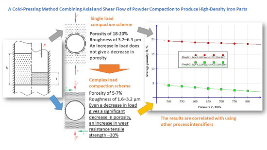
A Cold-Pressing Method Combining Axial and Shear Flow of Powder Compaction to Produce High-Density Iron Parts

by
Sergey N. Grigoriev
1,
Alexandr M. Dmitriev
2,
Natalya V. Korobova
2,* and
Sergey V. Fedorov
1
1
Department of High-efficiency Machining Technologies, Moscow State University of Technology STANKIN, Vadkovskiy per. 3A, 127055 Moscow, Russia
2
Department of Plastic Deformation System, Moscow State University of Technology STANKIN, Vadkovskiy per. 3A, 127055 Moscow, Russia
*
Author to whom correspondence should be addressed.
Technologies 2019, 7(4), 70; https://doi.org/10.3390/technologies7040070
Submission received: 8 July 2019 / Revised: 31 August 2019 / Accepted: 19 September 2019 / Published: 24 September 2019
(This article belongs to the Special Issue Processing and Fabrication of Advanced Materials)

Abstract

:
Highly performance methods for cold pressing (cold die forging) of preforms from iron powder with subsequent heat treatment and producing ready parts made of powder are described in the paper. These methods allow fabricating parts with smooth surfaces and improved mechanical characteristics—porosity, tensile strength. Application of the traditional design set-up with a single-axial loading is restricted to high stresses in the dies to deform the preforms that lead to cracks formation. New powder compaction schemes by applying active friction forces (shear-enhanced compaction) make it possible to unload dies and produce high-quality parts by cold pressing. The scheme allows moving the die in the direction of the material flow with a velocity that exceeds the material flow velocity.

Graphical Abstract

1. Introduction

Powder metallurgy is a technology for manufacturing products from metal powder or their compositions with non-metallic components, obtained by various manufacturing methods as mechanical grinding of metals in a vortex, vibration or ball mills, spraying liquid metals with compressed air or inert gases, recovery of ore or scale, electrolytic deposition of metals from solutions, or by use of a strong current applied to the metal rod in a vacuum [1,2,3]. Despite the variety of methods and current state of the powder market development, the production of powders stays the most time-consuming and expensive stage of powder metallurgy [4,5,6]. Physical, mechanical, and chemical properties of powders, as well as the granulometry and morphology of particles, influence significantly on the formation of bonds between particles during perform compaction and further sintering. That affects the properties of the final product [7,8,9,10,11].
In general, the technological process of powder metallurgy consists of four main stages: production of powders, mixing of powders, compaction (pressing, forming) and consequent sintering [12,13,14,15,16,17,18,19]. Often the way of powder compaction in preforms under all equal conditions predetermines the properties of the final product and takes a critical role in the formation of the internal structure (homogeneity, absence of pores, cracks) [20,21,22].
Powder metallurgy allows producing of the parts from new materials, for example, as pseudo-alloys from non-fusible-cast components, with controlled mechanical, magnetic, and others characteristics that cannot be achieved by any other production method [23,24,25,26,27,28,29,30,31,32].
Forming of preforms for production of the final product is carried out by cold pressing under high operational pressure up to 1000 MPa in metal dies of hard closed molds at the press tool, which is oriented vertically. The mixture of powders is freely poured into the cavity of the die between the upper and lower punch (Figure 1), or between several punches in the case of the production with several transitions [33]; the volume dosage is regulated by the course of the lower punch. The formed preform is pushed out of the cavity of the die lower punch. For molding is used specialized press equipment with mechanical, hydraulic or pneumatic drive. The resulting preform has the size and shape of the final product and sufficient strength for unloading and transportation to the sintering furnace. After that, the preform is sintered in order to improve its strength and ductile. For the production of high-precision parts, sintering performs in furnaces with reducing (hydrogen, dissociated ammonia) or protective (nitrogen, argon, endothermic gas) atmosphere. Sintering can be carried out in furnaces or using the method of forming combined with sintering by electric current pulses [34].
This article is devoted to research of the suitable compaction schemes with a complex load of iron powder before sintering. It should be noted that the authors did not research optimal design and schemes of compaction, as a study of optimality is a mathematical search for determining optimality itself. In the case of powder metallurgy compaction schemes, it can be results of multi-factors influence, where the criteria of optimality include such parameters of the obtained preforms as porosity and density of the samples, roughness, and a complex of physical and mechanical properties. That all is too large for a single manuscript, which introduces innovative schemes of load and several working designs of stamps, which were tested in the conditions of real production. Meanwhile, the search of optimal stamp construction and compaction schemes is a good purpose for further research.
The pressure of compaction of iron powders varies between P = 500–800 MPa (50–80 kg/mm2). The point is about water (grade series WP) and air (grade series RZ) atomized pure iron powder with restored chemical purity and ultimate particle size from 160 to 200 µm, average bulk density γ of 2.6–2.8 g/cm3 [35,36] according to its mechanical properties and assignation. As practice showed, if the pressure is less than 500 MPa or more than 800 MPa, the preform can crack and break. With the forming pressure P in the range of 500–800 MPa applied simply, the preform shows high porosity (around 15–18%) [37,38,39,40,41,42]. With such a porosity, the preform after sintering can demonstrate insufficient strength and ductility [43].
The goal of the current research is to investigate factors affecting the density of preforms made by the developed method of a complex load: the simultaneous application of compressive stress P and shear stress τ and draw the conclusions on recommended design of cold-pressing set-up for the implementation of this method.

2. Methods and Materials

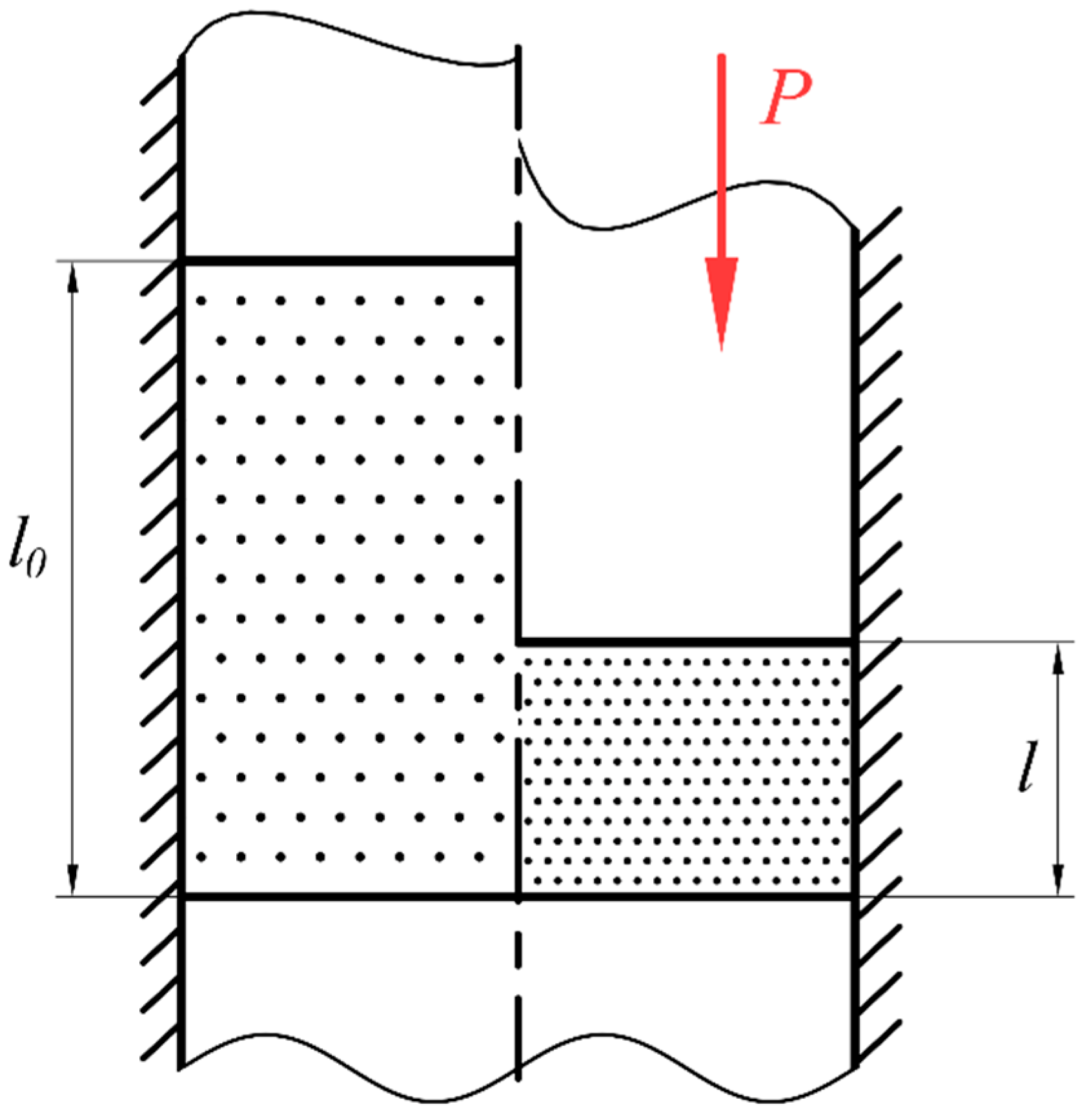
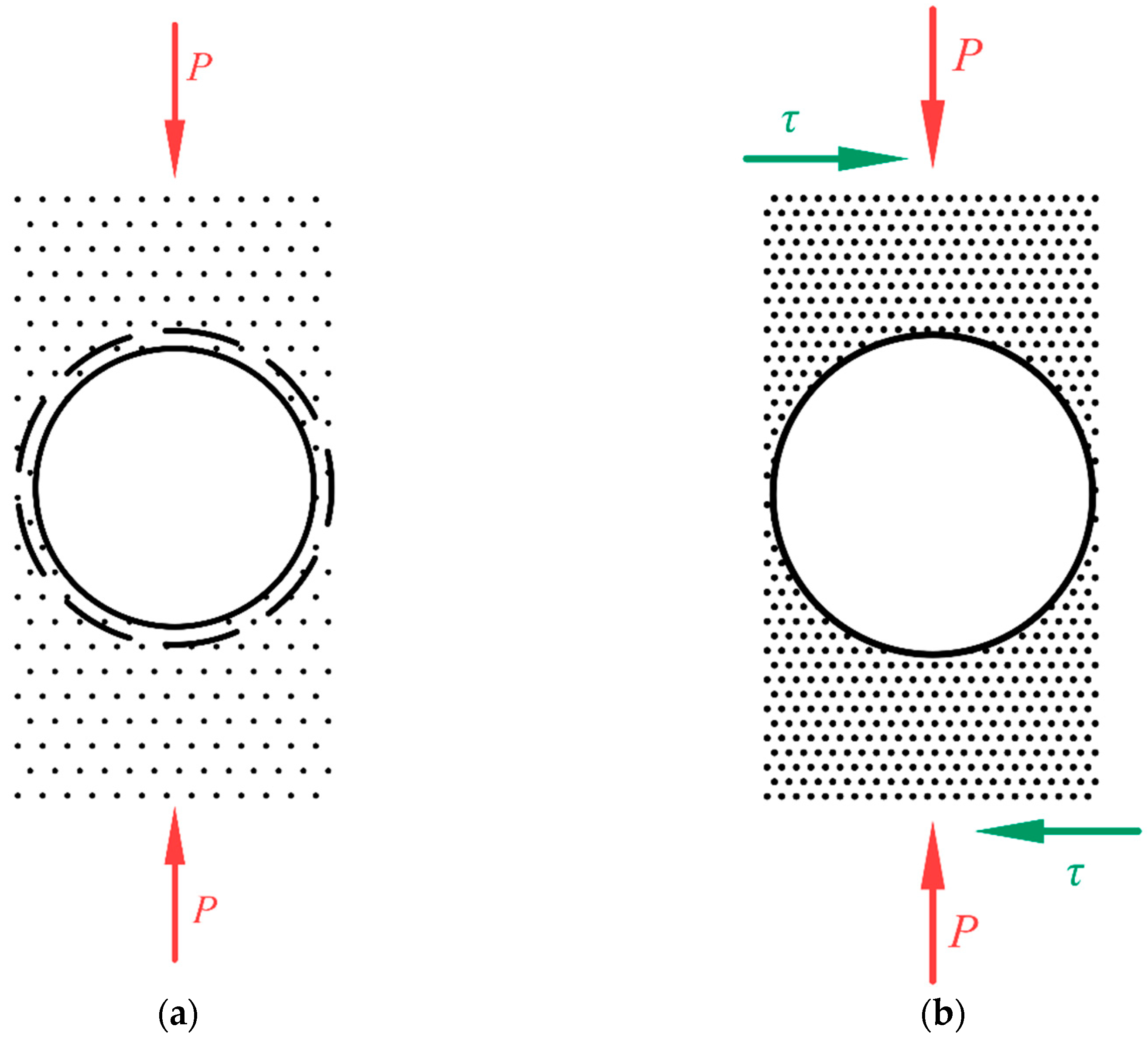
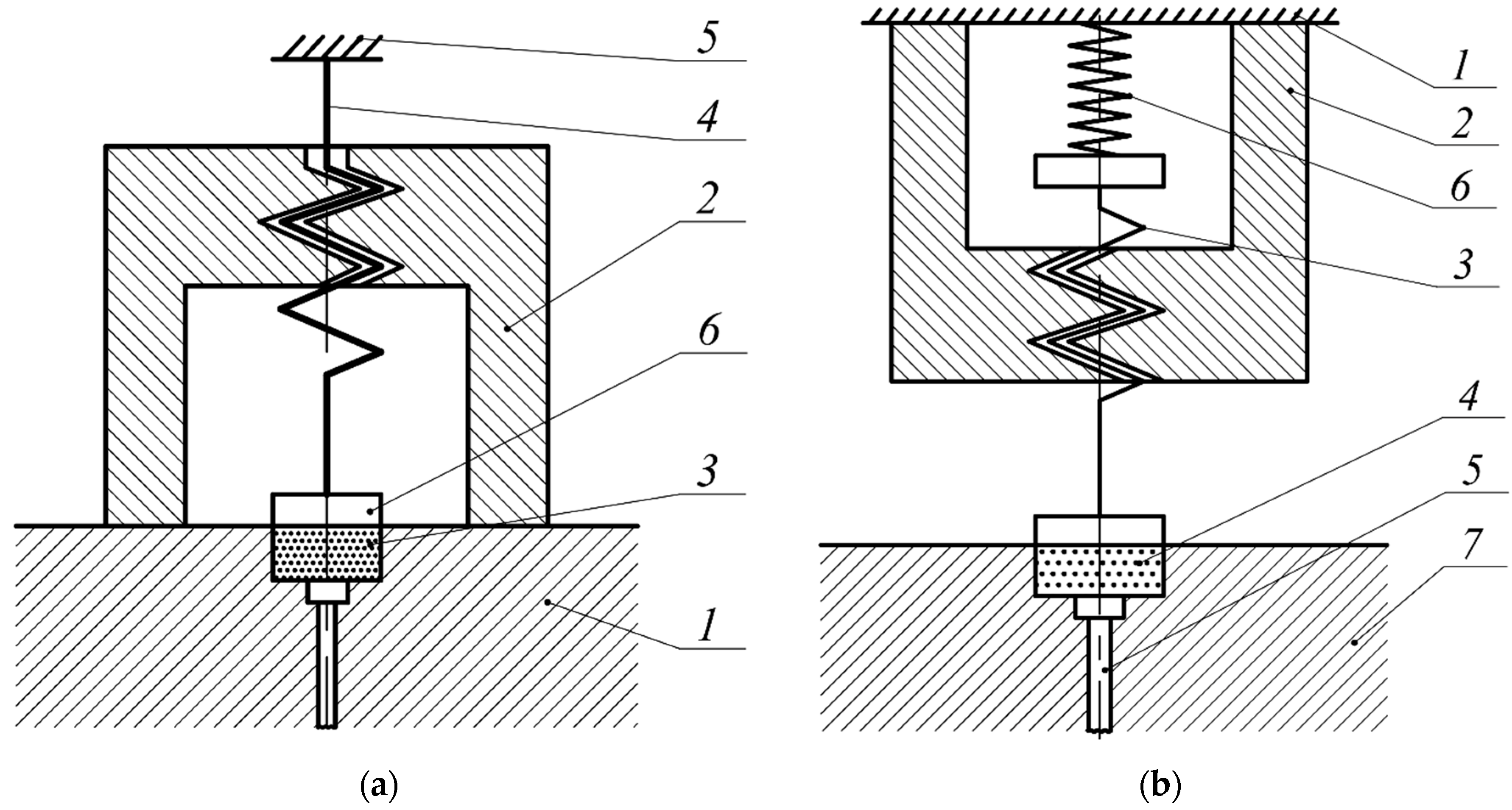
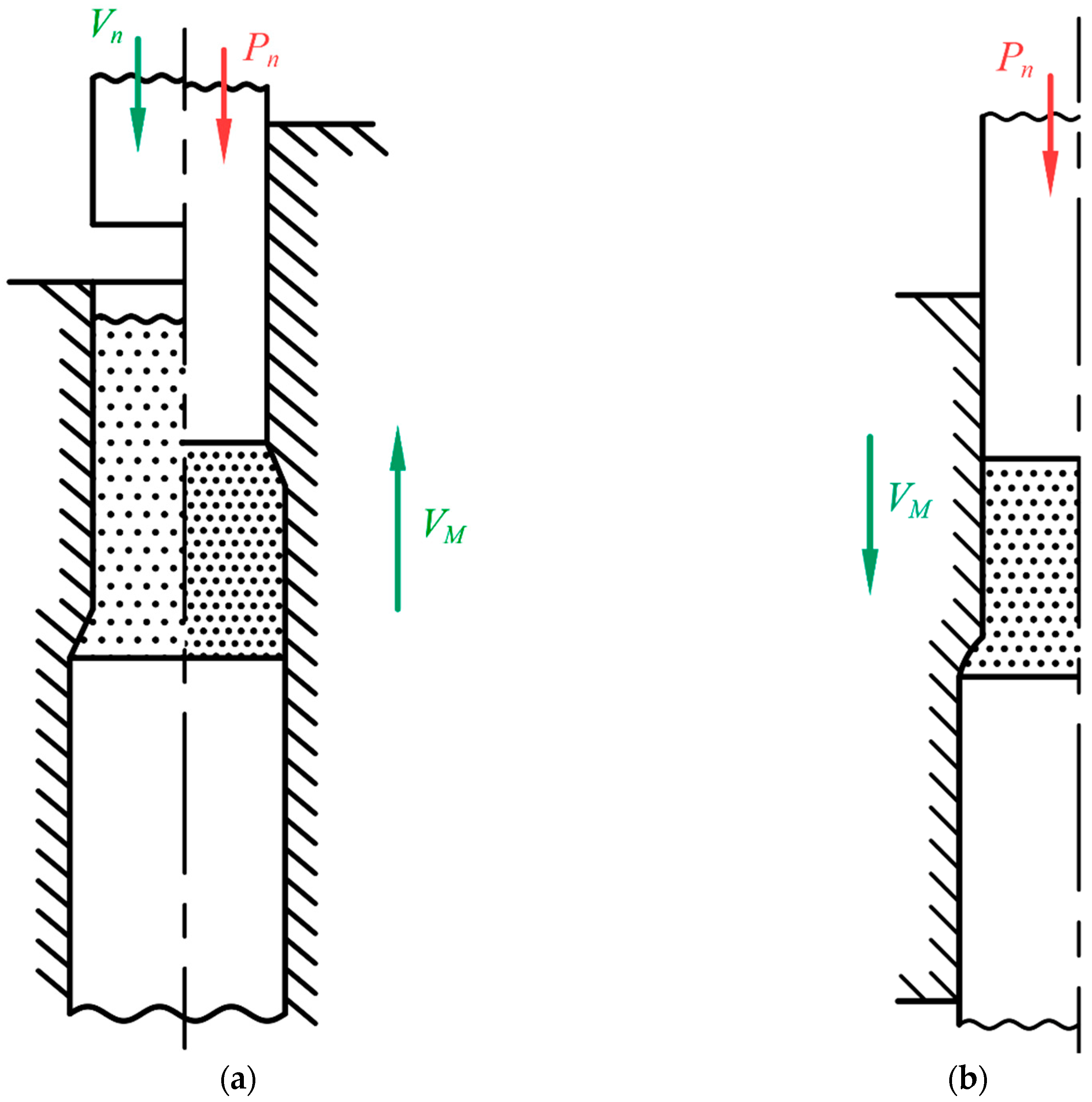
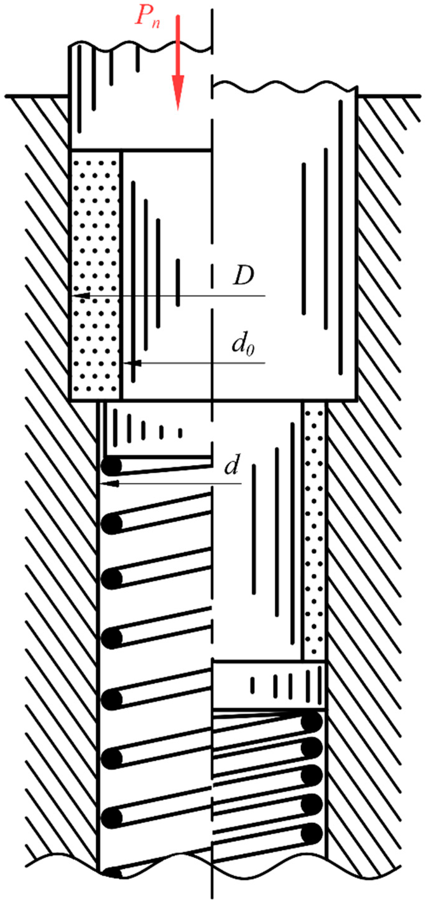
2.1. Developed Method of Complex Load

The possible reason why the quality of obtained preforms after single-load scheme of compaction cannot be sufficient at a pressure above 800 MPa can be specific zones of resistances—micron-sized cavities or macro-pores [44,45,46,47]. They can be interpreted as arch construction composed from particles that can withstand high stresses, when the load increases, the arch (of a pore) formed by adhesion and chemical bonds of atoms of particles’ surface only becomes denser and stronger, this inhibits further preform compaction [20,31,32,34,48,49]. Preliminary experiments and existed practice showed that the surface that forms pores cracks with a further increase in load. However, the preform cracks as well.
This fracture of the sample is due to insufficient compaction of the powder to achieve reliable adhesion bonds between its particles. The possible reason for it at pressures above 800 MPa is shown in Figure 2a, where the letter P denotes the specific force compressing the powder poured into the stamp. The circle shown by the solid line indicates a pore formed during powder compaction having a macroscopic size (from now on macro-pore).
The resulting macro-pores resist compaction. Before these pores close, the so-called “re-pressing” cracks are initiated on macro-pores’ surface under the action of P as it was shown in Figure 2a by a dashed line. Then the workpiece is destroyed upon further compression. Subsequent sintering of the molded sample practically does not change its residual porosity.
The situation can be improved by adding additional intensifier of processing—a shear stress τ in combination with a single axis load P (Figure 2b), and then the pore closes with no cracks form on its surface. It can be related to a hypothesis that the shifts between particles under the influence of stresses of shear flow τ contribute to the destruction of adhesion and chemical bonds of the surface of powder particles that compose an arch; the microplastic deformation of particles occurs that forms new comprehensive adhesion and chemical bonds between particles [50,51]. It improves the conditions for subsequent sintering of the sample and its final porosity and properties.
In work, the iron powder is subjected the load with the shift of the powder layers to avoid the described above problem and for manufacturing high-density preforms. The shifts are generated by using active forces of contact friction [52]. The experience showed that if compressive stress P and shear stress τ are applied simultaneously, the preform is stayed sufficient strength for further relocating. That can be associated with pores closing and enhancement of the adhesion bonds and redistribution of local stresses [53,54,55,56,57]. With an increase in the load, microcracks arise near the boundaries due to the large accumulation of dislocations, resulting in brittle fracture [58,59,60,61].
As it is well known from the practice, the existed in preforms macro-pores present barriers for efficient compaction up to high densities in vertically oriented compaction scheme. The density reaches saturation when increasing the compaction stress during conventional cold pressing with a single-axial loading (Figure 2a). The different design of the cold-pressing set-up that relies on creating a shear flow τ in the powder preform are proposed to mitigate this (Figure 2b). Thus, a high density of iron compacts can be achieved. The known principal idea as shear-enhanced compaction [62,63] was approbated in new simple engineering design of dies and preforms.

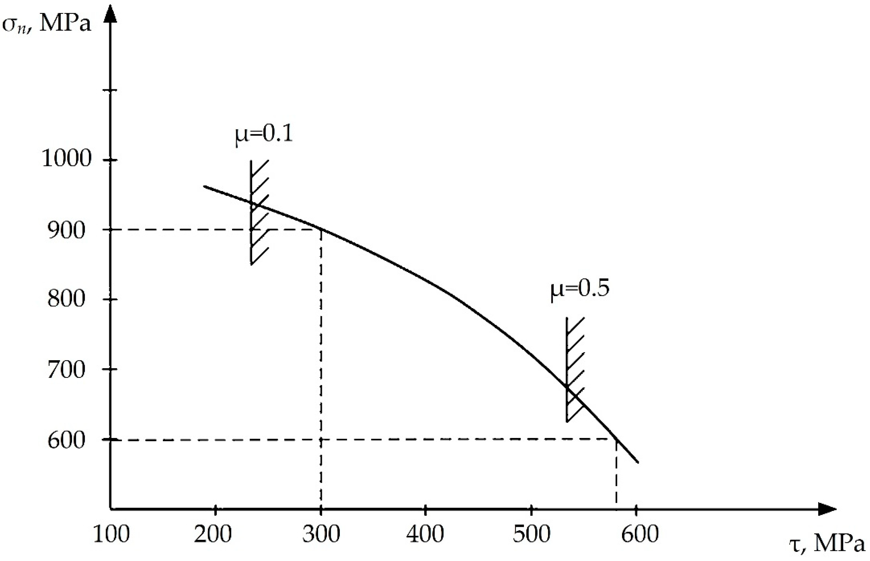
2.2. Coefficient of Friction

Figure 3 shows various combinations of cylinder axial stress in the workpiece σn and shear stress τ, at which we managed to obtain fixed density ρ = 7.1 g/cm3 in the compacted preform.
Apart from the combination of stresses, the crucial factor affecting forming is the friction coefficient µ between the interacting surfaces of the wall and powder preform—die-wall friction [64,65]. When μ is below a certain value, increasing τ results in unwanted slipping between the tool and the powder preform surface that breaks the process [43]. The diagram shows two example values of μ that in effect put a limit on increasing τ.
Various coefficients of friction μ were obtained standardly—by changing the medium between the interacting surfaces of:
  • The pair of “wall—powder workpiece”— the use of standard lubricants;
  • between the particles of the powder—the use of a plasticizer introduced into the prepared powder mixture.
The choice of lubricant depends on the required coefficient of friction. This diagram is necessary for researchers who can determine the relationship between axial and tangential stresses in the pressed workpiece for a given coefficient of friction to control the pressing process using the controlled movements of the machine.

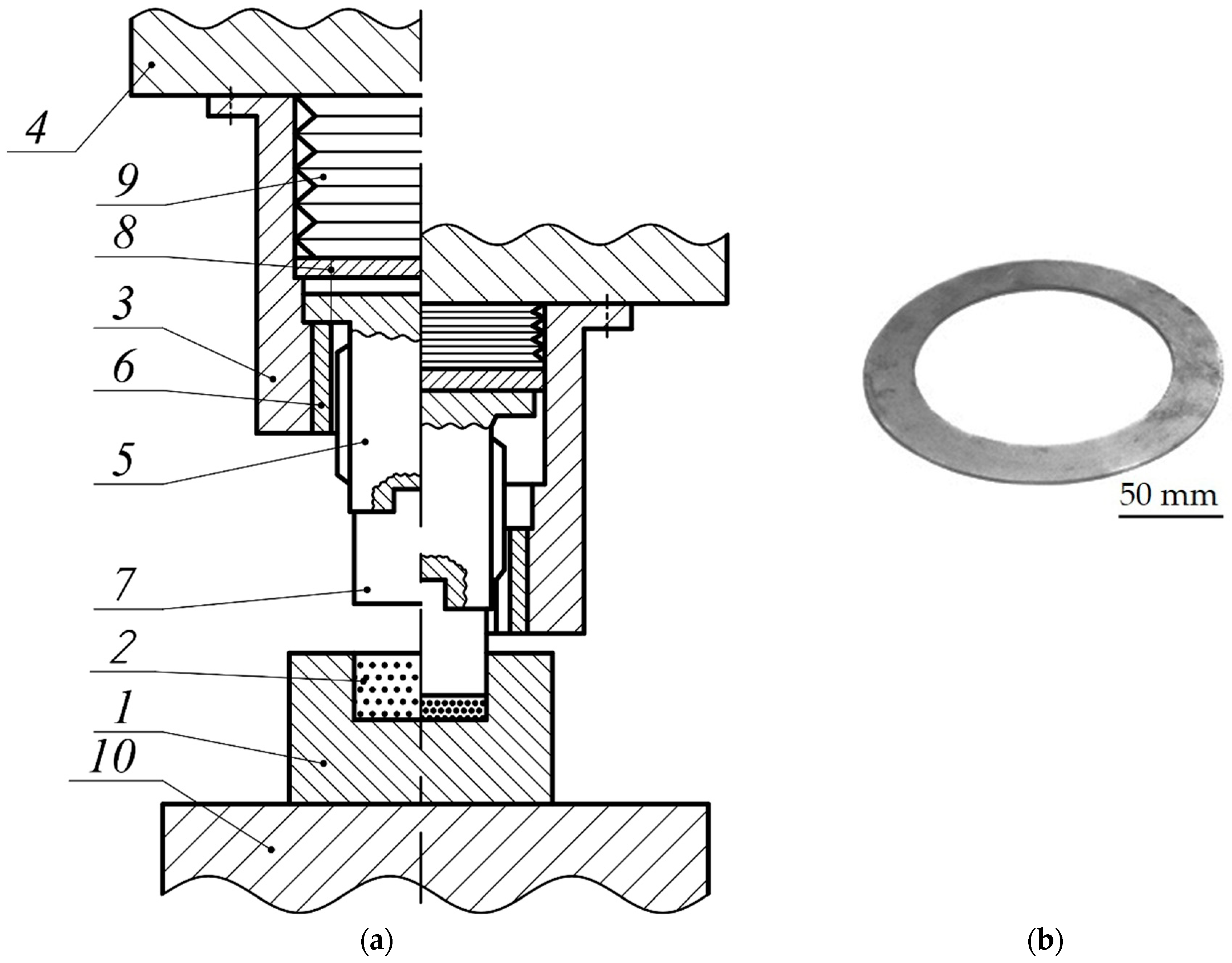
2.3. Material and Equipment

The preform is made from water atomized pure iron powder PZhV2.160.2 powder (JSC Sulinsky Metallurguchesky Zavod, Krasny Sulin, Russia), which was produced under license and the analog of the widespread WPL200 powder [66,67] produced by Mannesmann Demag (Renningen, Germany). The chemical composition of the powder presented in Table 1.
A modified version of EPM-800H/S (Anshan TAIHANG Electronic Power Co Ltd., Beijing, PRC) was used for compacting preforms as a press tool. The press tool has multi-way bidirectional pressing mode for pressing the preforms for the parts high requirement for equal density or thickness of the molded product [69]. In this case, the lower punch does not move, the upper punch enters the die and presses the powder, the die does not move. The upper punch reaches a halfway, when the punch and die begin to move synchronously downwards, creating pressure in the downward direction. Multi-way pressing is modeled and the product gains uniform density throughout its thickness. The movement of the upper punch and die is programmable and controlled by special sensors. Sintering of the preforms was performed at a hot isostatic press equipment American Isostatic Presses (Columbus, USA) for impact on the material of high temperature and pressure that assists in achieving of equal shrinkage and density of the products.
It should be noted, in the machine indicated in the article, the upper punch and matrix can move up and down. The bottom punch is always stationary. The movement according to the scheme under consideration is as follows: first, the upper punch moves down with a certain increasing force (due to an increase in the resistance of the powder material being compacted, i.e., a decrease in the pore space), this happens until the upper punch reaches a certain point at which the powder is no longer compacted. For further compaction of the powder workpiece, a shift (shear flow τ) is necessary, which is realized by simultaneously moving the matrix and punch down.

2.4. Characterization of the Samples

Porosity of the samples was mainly controlled according to ISO 5017-88. A Pascal 440 porosimeter (Thermo Scientific, Waltham, USA) was used to obtain additional data that contributed to drawn more objective conclusions.
The surface roughness was estimated by a Hommel Tester profilograph-profilometer (Jenoptik Industrial Metrology, Villingen-Schwenningen, Germany) with a range of measuring of 8, 80, 800, 8000 µm (depending on the used probe; resolution from 1 to 1000 nm); measurement error—2%.

3. Results

3.1. Manufacturing of Thin Round Parts

One of developed designs of a stamp for the creation of shear stress τ is shown in Figure 4a. Lower plate 1 with the die containing powder 3 is mounted on the press table. Nut 2 is based on the lower die plate 1. Press slider 5 acts on the down feed screw 4 with a punch 6. The thread angle of the screw 4 and the nut 2 should be at least 18°. If this angle is less than 18°, the screw will not rotate due to the friction in the thread.
The design of the stamp in Figure 4a has a fixed ratio of translational and rotational motions of the tool. In addition, there is a great loss of the pressing force due to the friction in the thread. The impact to the workpiece is just about 2.5–3 MN with the press power of 5 MN (500 ton), so the effectiveness of the system is ~50–60%.
Another efficient stamp construction is shown in Figure 4b. Nut 2 is connected with press slider 1. Inside the frame with nut 2, there is down feed screw 3 with a punch at its lower end. Powder preform 4 is placed in the cavity of the die in bottom plate 7. Ejector 5 is used to extract the preform from the die. The most important part of this scheme is spring element 6 located between the upper end of the screw and the press slider. If spring element 6 did not exist, the axial force would be created only by friction in the thread between screw 3 and nut 2. In the ideal case, when the thread is frictionless, this force is absent. However, the presence of the spring element results in the additional axial force, which makes the whole design more efficient. In this stamp, the full press power (5 MN) applies to the powder preform. The ratio of the direct and rotational movements of the punch is controlled by the rigidity of the spring element 6 at a constant thread angle of the nut 2 and screw 3.
It should be noted that die tooling was installed on the table of a hydraulic press with force (5 MN). For a hydraulic press, excess force does not have dire consequences, as is the case with crank machines (or any other with a hard stroke). Nevertheless, the calculation of the spring element, inserted into the rig, is for this purpose that the increase in force in the press will not be observed. This is for the designer quite real and standard calculations of the spring element.
This scheme was embodied in the design of the function stamp (Figure 5a).
The design of the stamp includes die block 1 with cavity 2 for powder, which is based on press table 10; frame 3 fixed to upper plate 4. Inside frame 3, screw 5 and nut 6 are arranged. Nut 6 is fixed to frame 3, and screw 5 in the initial position to prevent from falling out of nut 6 by its flange. At the lower end of screw 5, there is punch 7. Inside frame 3 with the initial gap in the upper end of screw 5, there is restrictive plate 8, which is placed under spring element 9. Preliminary compression of spring element 9 is performed during mounting of frame 3 to upper plate 4 and it is regulated by selection of the thickness of restrictive plate 8.
Screw 5 is a multiple-thread screw with the thread angle of 18°. The stamp operates as follows. Once cavity 2 of die block 1 is filled with powder, upper plate 4 with frame 3, nut 6, screw 5, based in its original position on nut 6 by its flange, and punch 7, move down. At the initial moment of the working stroke of punch 7, screw 5 starts to rotate forcefully inside nut 6. Rotation is fastest at this moment, and has one beneficial side effect: the upper end of the powder is leveled under the weight of the rotating screw and punch. Once the upper end of the screw touches restrictive plate 8, the latter applies additional force to the screw. Screw 5 moves then together with frame 3 and nut 6, producing preforming of the powder. Once the force on the upper end of screw 5 becomes higher than the preload force of spring element 9, screw 5 with nut 6 moves together with restrictive plate 8 inside of frame 3. As a result, the axial movement of punch 7 carries out the final forming of the powder while it rotates.
After forming of the workpiece, the reverse movement of upper plate 4 returns restrictive plate 8 and screw 5, under the pressure of spring element 9 and their weight, to their initial position. They continue to move up simultaneously with frame 3 and nut 6 in order to set free the workpiece, which is eventually unloaded from the die block 1 using an extractor.
Figure 5b presents a photo of a preform produced with this stamp. Note that the preform is extremely thin, which would be impossible to achieve without initial leveling of the powder by the rotational movement of the screw and punch described above.
It should be noted that the effectiveness of creating a shear movement of powder particles depends on the initial thickness of the powder layer in the die. The recommendations on shear stress for producing high-density thin parts for both low ring semi-finished products [20] and cylindrical blanks [32,34,43] were discussed in details previously.

3.2. Manufacturing of Thick Round Parts

The previous section described the manufacturing features of thin parts from iron powder. The shifts inside the powder mass were also used to manufacture parts with much higher height. The preform is compacted as it is shown in Figure 6.
Two schemes were proposed to achieve low residual porosity of workpieces for deformation of powder preforms, which change not just the density of the workpiece, but also its shape.
Changing the shape of a preform is always associated with the shifts in a preform. We create shear stress in the preform using a die with changing inner diameter. The first scheme of forming involves preform compaction with its simultaneous expansion when moving from the top of the cylindrical die cavity of 32 mm in diameter to the lower cylindrical cavity with a diameter of 36 mm (Figure 6a).
The second scheme involves the same two operations as it was shown in the first scheme and then compressing the preform from the 36 mm- to the 32 mm-cavity (Figure 6b).
In the proposed forming schemes pressure P is applied to the end of the forming preform. P is defined as force Pn divided by the cross-sectional area of the punch.
In the first scheme, specific force Pn was in the range of 850–900 MPa when in the second one, Pn did not exceed of 300–350 MPa. Thus, in the second scheme, the applied force was reduced by 2.6–2.8 times relative to the first scheme by making two movements of the die instead of one.
It should be noted that hereby this is not about pressure, but about specific force, i.e., the applied force on the surface of the powder in the tool, referred to the surface area of the punch. A decrease in axial stresses and an increase in tangent ones, which are related to the characteristic features of the second scheme, leads to a decrease in axial force due to the active work of contact friction forces.

3.3. Extrusion and Lubrication of Preforms

After forming of the powder preforms, they are sintered. After that, additional extrusion and lubrication using our method described below may be applied to them.
Lubrication is accomplished by applying the coating consisting of two the most widespread lubricates in powder metallurgy-graphite and zinc stearate powders, which were mixed in equal parts, to the sintered preform prior to its extrusion. During extrusion, coating material fills the pores in the surface layer of the workpiece. As a result, during the subsequent heat treatment of the preform carburization of its surface is achieved. The resulting steel casing (thick coating) greatly improves the mechanical characteristics of the parts.
Application of coating is performed by placing the sintered preform in a die cavity having larger diameter D than preform diameter d0 (Figure 7).
The free space in the die around the preform is filled with a mixture of graphite powder and zinc stearate powder. After filling the powder surrounding the preform, it is pushed into the die cavity, which has diameter d equal to the diameter of the coated preform. Pushed by the pressure, the coating powder mix is converted into a compact casing, which is firmly retained on the surface of the sintered preform (Figure 8a).
Extruding parts from the covered preforms are performed conventionally. The cased preform is placed into the die, and a punch produces extruding. The pressure from the preform to the die walls is 1000–1500 MPa. This force presses the cased material into the pores on the surface of the workpiece [70,71,72,73].
Zinc stearate contained in the coating mix acts as a lubricant and allows reducing the force on the extruding punch. In this method, it is advisable to heat the die to make the lubricant coating liquid. Raising the temperature of the die to 280 °C, while reducing the preform density to 85%, significantly reduces the squeezing force compared to the extrusion of the uncoated preform—by more than 23%. Further reduction of the pressure may be achieved using the method described in [74].
During subsequent heat treatment of the part, which is carried out, in particular, to relieve the residual stress, the carbon in the pores of the surface layer chemically reacts with iron from which the part is manufactured, and a thin steel casing is formed. As a result, durability and hardness of the part are improved. Furthermore, additional hardening of the part may be performed by cooling it quickly.
Parts manufactured from iron powder using the method described above are shown in Figure 8b.

4. Discussion

The analyses of the porosity of the samples as thin round parts obtained by two schemes—traditional single axial load and with complex load were carried out. The obtained data (Figure 9) were interpolated and correspond to the known data in common trends [75].
The character of pores had closed morphology; the obtained data showed that the smallest detected pores were in the range of 68–70 nm, but the percentage of these pores in the researched surface was less than 0.3%. The average diameter of the pores was in the range up to 1–20 µm.
The shown porosity of the preforms can influence positively on heat and wear resistance, tensile strength (~30% by analyzed data) of the final product [76,77,78,79,80,81,82]. It should be noted that ultimate stress tensile was pre-estimated by true-stress true-strain tensile test and fitting curves for bulk specimens obtained by equations shown in [65] and the Ludwik equation [83]. As it can be seen from the graphs, the proposed scheme of load showed and proved its effectiveness; the average porosity improved by ~10–15% in comparison with the conventional scheme of load and can be recommended for thin round parts.
The roughness of the samples was improved from Ra = 3.2–6.3 µm for the single load scheme (Rz = 10–20 µm) to Ra = 1.6–3.2 µm in the case of complex load.
The detailed research of the porosity and the roughness of the obtained samples with the proposed schemes can be done during further comprehensive research for the next publication work to avoid overloading of the current paper.
The preform, which is shown in Figure 5b, is thin and has high density—around 96–98 percent relative to the density of a part stamped from a steel blank with equal chemical composition. At the same time, the part produced from powder has some additional properties that are useful, for example, in friction mechanisms. The parts, which are shown in Figure 8b, have high density and smooth surfaces, whereas their shape is entirely different. This demonstrates that the developed methods make it possible to produce a broad spectrum of high-quality parts from iron powder.
The question of the influence of the surface roughness of the die/mold inner surfaces were not investigated in the frames of current research, but deserve attention for further study. By pre-estimated data, the roughness of these surfaces can have a beneficially impact on increasing the shear stress.
The influence of the friction coefficient on the parameters of samples deserves an additional detailed study. In the current research, it was evaluated the impact of the proposed lubricant on the reduction of the extrusion forces, which reaches 23%.
Various designs were considered for powder compaction that allows creating a combination of the axial and shear stresses for achieving higher densities of the final product. For a better understanding of the positive influence of the proposed schemes, the authors calculated the efficiency of compaction by [84]:
Θ = ρ 2 Δ ρ 2 · Δ ρ 1 ρ 1 ,
where ρ1—relative density of the powder system in the conventional scheme; ρ2—relative density of the powder system with complex load; Δρ—relative density gain. In this case, relation ρ Δ ρ is a quality parameter of powder body. By estimated data, calculated efficiency of the proposed scheme for thin round parts achieves ~95%.
The investigation confirmed the high importance of the compaction schemes in production of parts from iron powder for providing specific properties as low porosity and high-density of the mesostructure of the parts that influence on its precision and performance of the production and final exploitation properties of the parts. Shifts are generated by using active forces of contact friction contribute compressive stress P accompanied by shear stress τ simultaneously to close the internal spaces between the powder particle in the die.
It should be noted that the obtained results can be correlated with the results obtained at the schemes of compaction with the alternative source of the process intensifiers as ultrasound, electric or magnetic pulses [43,85,86,87,88,89,90,91,92,93]. In all of the cases, the better results can be achieved for the materials of transition metals group (Fe, Cr, Ni) that have an uncompensated spin in compounds for the formation of an adhesive bond. It related to the fact that these atoms have unfinished internal electron shells.
Thus, the spin of an electron participating in a chemical bond can be reoriented to fill anti-binding orbitals, which can lead to subsequent bond decay. After bond breaks, single impurity atoms diffuse across the crystal and are trapped at distorted interfaces.
A feature of all these phenomena is that these processes causing a change in properties occur at room temperature. Of most considerable interest is the diffusion mobility of atoms, the occurrence of lasing processes.
It is natural to assume that, because of a combined effect on materials, microplastic deformation occurs and the chemical bond between the particles, unlike the mechanical one, is a volume hardening of the shape. The mechanism of this process is as follows.
With a shift in the interdomain boundaries, the directions of the electron spin moments change, which is accompanied by deformation and the associated elastic stresses. That leads to a redistribution of local stresses. In these places, the processes of reproduction and dislocation movement are most intensive and, thus, foci of plastic deformation are formed, causing the formation of an adhesive bond. However, if you expose the workpieces with too large shear loads, then because of the significant accumulation of dislocations near the boundaries, microcracks arise, which ultimately lead to brittle fracture.

5. Conclusions

In work, the hypothesis on the existed in preforms macro-pores, which create the barriers for efficient compaction up to high densities in compaction schemes with a single-axial loading is confirmed. Then the preform density reaches saturation when an increase in compaction specific force during cold pressing does not have a right impact on further compaction. Alternative designs of the cold-pressing set-ups that rely on creating a shear flow τ were proposed. The experiments showed that the density of the samples increases when the porosity decreases (~10–15%) in comparison with the conventional scheme by applying the alternative schemes of compaction with the simultaneous vertical load and shear flow. That influence significantly on mechanical properties of the samples (~30%).
The first proposed scheme for production thick round parts, where operational pressure was in the range of 850–900 MPa, proved its ineffectiveness in comparison with the second one, where the operational pressure did not exceed of 300–350 MPa due to the unidirectional impact of the force and movement of the punch making two movements of the die instead of one.
The proposed scheme for pressing of thin round part preforms proved its effectiveness in the production of an extra-thin ring preform of 0.3 mm-thickness with the diameters of 130 and 95 mm correspondently. The proposed scheme showed up to ~95% of the effectiveness of the applied pressing forces by the spring element located between the upper end of the screw and the press slider, which contributes additional axial forces for creation shear stresses in the working zone that reduces friction between working surfaces of the mold.
The developed method for graphite lubrication of the parts creates the casing that case the pores and reduces the extrusion forces by 23% due to its lubricant properties under a temperature of 280°C.

6. Patents

  • Korobova, N.V.; Dmitriev, A.M.; Aksenenko, A.Yu. Stamp for Obtaining Cylindrical Metal Parts with a Homogeneous Short-Grain Structure from Bars; RU 2629576, 30.12.2015.
  • Korobova, N.V.; Dmitriev, A.M.; Grigoriev, V.V.; Aksenenko, A.Yu. Device for Moving Billets in Solid-Liquid Conditions; RU 133441, 05.04.2013.

Author Contributions

Conceptualization, S.N.G., A.M.D.; methodology, N.V.K.; software, S.V.F.; validation, N.V.K.; formal analysis, A.M.D.; investigation, N.V.K.; resources, S.V.F.; data curation, N.V.K., S.V.F.; writing—original draft preparation, N.V.K.; writing—review and editing, A.M.D., S.N.G.; visualization, S.V.F.; supervision, A.M.D.; project administration, S.N.G.; funding acquisition, S.N.G.

Funding

In the frame of the government task of the Ministry of Education and Science of the Russian Federation to conduct fundamental scientific research in priority areas determined by the Presidium of the Russian Academy of Sciences (N11.1817.2017/4.6).

Acknowledgments

The research was conducted at laboratories of the Department of High-Efficiency Machining Technologies and Department of Plastic Deformation System of MSTU Stankin.

Conflicts of Interest

The authors declare no conflict of interest.

References

  1. Grigoriev, S.N.; Sinopalnikov, V.A.; Tereshin, M.V.; Gurin, V.D. Control of parameters of the cutting process on the basis of diagnostics of the machine tool and workpiece. Meas. Tech. 2012, 55, 555–558. [Google Scholar] [CrossRef]
  2. Grigoriev, S.N.; Fominski, V.Y.; Romanov, R.I.; Gnedovets, A.G.; Volosova, M.A. Shadow masked pulsed laser deposition of WSex films: Experiment and modeling. Appl. Surf. Sci. 2013, 282, 607–614. [Google Scholar] [CrossRef]
  3. Grigoriev, S.; Metel, A. Plasma-and beam-Assisted deposition methods. NATO Sci. Ser. 2004, 155, 147–154. [Google Scholar]
  4. Floren, H.; Frishammar, J.; Lof, A.; Ericsson, M. Raw materials management in iron and steelmaking firms. Miner. Econ. 2019, 32, 39–47. [Google Scholar] [CrossRef]
  5. Sista, K.S.; Dwarapudi, S. Iron Powders from Steel Industry by-Products. ISIJ Int. 2018, 58, 999–1006. [Google Scholar] [CrossRef]
  6. Gallardo, J.M.; Agote, I.; Astacio, R.; Schubert, T.; Cintas, J.; Montes, J.M.; Torres, Y.; Cuevas, F.G. Hard Metal Production by ERS: Processing Parameter Roles in Final Properties. Metals 2019, 9, 172. [Google Scholar] [CrossRef]
  7. Agrawal, A.; Dube, R.K. Methods of fabricating Cu-Al-Ni shape memory alloys. J. Alloys Compd. 2018, 750, 235–247. [Google Scholar] [CrossRef]
  8. Herraiz Lalanaa, E. Permanent magnets and its production by powder metallurgy. Rev. Metal. 2018, 54, e121. [Google Scholar]
  9. Palmero, P. Structural Ceramic Nanocomposites: A Review of Properties and Powders’ Synthesis Methods. Nanomaterials 2015, 5, 656–696. [Google Scholar] [CrossRef]
  10. Letenneur, M.; Brailovski, V.; Kreitcberg, A.; Paserin, V.; Bailon-Poujol, I. Laser Powder Bed Fusion of Water-Atomized Iron-Based Powders: Process Optimization. J. Manuf. Mater. Process. 2017, 1, 23. [Google Scholar] [CrossRef]
  11. Qin, Q.; Yang, F.; Shi, T.; Guo, Z.; Sun, H.X.; Li, P.; Lu, X.; Chen, C.G.; Hao, J.J.; Cao, P. Spheroidization of tantalum powder by radio frequency inductively coupled plasma processing. Adv. Powder Technol. 2019, 30, 1709–1714. [Google Scholar] [CrossRef]
  12. Petrov, G.V.; Shneerson, Y.M.; Andreev, Y.V. Extraction of Platinum Metals During Procssing of Chromium Ores from Dunnite Deposits. J. Min. Inst. 2018, 231, 281–286. [Google Scholar]
  13. Balog, M.; Ibrahim, A.M.H.; Krizik, P.; Bajana, O.; Klimova, A.; Catic, A.; Schauperl, Z. Bioactive Ti plus Mg composites fabricated by powder metallurgy: The relation between the microstructure and mechanical properties. J. Mech. Behav. Biomed. Mater. 2019, 90, 45–53. [Google Scholar] [CrossRef] [PubMed]
  14. Nicoara, M.; Buzdugan, D.; Locovei, C.; Bena, T.; Stoica, M. About thermostability of biocompatible Ti-Zr-Ag-Pd-Sn amorphous alloys. J. Therm. Anal. Calorim. 2018, 133, 189–197. [Google Scholar] [CrossRef]
  15. Metel, A.; Bolbukov, V.; Volosova, M.; Grigoriev, S.; Melnik, Y. Equipment for Deposition of Thin Metallic Films Bombarded by Fast Argon Atoms. Instrum. Exp. Tech. 2014, 57, 345–351. [Google Scholar] [CrossRef]
  16. Sezer, N.; Evis, Z.; Kayhan, S.M.; Tahmasebifar, A.; Koc, M. Review of magnesium-Based biomaterials and their applications. J. Magnes. Alloys 2018, 6, 23–43. [Google Scholar] [CrossRef]
  17. McDevitt, E.; Minisandram, R.; Garcia-Avila, M. The Case for Physical Experiments in a Digital Age. Miner. Metals Mater. Ser. 2018, 941–956. [Google Scholar] [CrossRef]
  18. Volykhov, A.A.; Sanchez-Barriga, J.; Sirotina, A.P.; Neudachina, V.S.; Frolov, A.S.; Gerber, E.A.; Kataev, E.Y.; Senkovsky, B.; Khmelevsky, N.O.; Aksenenko, A.Y.; et al. Rapid Surface Oxidation of Sb2Te3 as Indication for a Universal Trend in the Chemical Reactivity of Tetradymite Topological Insulators. Chem. Mater. 2016, 28, 8916–8923. [Google Scholar] [CrossRef] [Green Version]
  19. Kotoban, D.; Grigoriev, S.; Okunkova, A.; Sova, A. Influence of a shape of single track on deposition efficiency of 316L stainless steel powder in cold spray. Surf. Coat. Technol. 2017, 309, 951–958. [Google Scholar] [CrossRef]
  20. Dmitriev, A.M.; Korobova, N.V.; Badalyan, A.Z. Development and Research of Formation Technologies on Specialized Presses With Subsequent Sintering of High-Density Details From Iron-Based Powders. J. Min. Inst. 2019, 236, 216–228. [Google Scholar] [CrossRef]
  21. Ferreira, S.C.; Conde, A.; Arenas, M.A.; Rocha, L.A.; Velhinho, A. Anodization Mechanism on SiC Nanoparticle Reinforced Al Matrix Composites Produced by Power Metallurgy. Materials 2014, 7, 8151–8167. [Google Scholar] [CrossRef] [PubMed] [Green Version]
  22. Xu, C.; Liu, F.; Huang, L.; Jiang, L. Dependence of Creep Performance and Microstructure Evolution on Solution Cooling Rate in a Polycrystalline Superalloy. Metals 2018, 8, 4. [Google Scholar] [CrossRef]
  23. Chauhan, S.; Verma, V.; Prakash, U.; Tewari, P.C.; Khanduja, D. Studies on induction hardening of powder-Metallurgy-Processed Fe-Cr/Mo alloys. Int. J. Miner. Metall. Mater. 2017, 24, 918–925. [Google Scholar] [CrossRef]
  24. Rezaei, A.; Hosseini, H.R.M. Evolution of microstructure and mechanical properties of A1-5 wt% Ti composite fabricated by P/M and hot extrusion: Effect of heat treatment. Mater. Sci. Eng. A 2017, 689, 166–175. [Google Scholar] [CrossRef]
  25. Colombini, E.; Bocchini, G.F.; Parigi, G.; Sola, R.; Veronesi, P.; Poli, G. Laser hardening of homogeneous and inhomogeneous p/m steels. Metall. Ital. 2015, 10, 15–24. [Google Scholar]
  26. Rivolta, B.; Gerosa, R.; Silva, G.; Tavasci, A.; Engstrom, U. Wear performances of surface hardened PM steel from pre-Alloyed powder. Wear 2012, 289, 160–167. [Google Scholar] [CrossRef]
  27. Nosewicz, S.; Rojek, J.; Chmielewski, M.; Pietrzak, K. Discrete Element Modeling of Intermetallic Matrix Composite Manufacturing by Powder Metallurgy. Materials 2019, 12, 281. [Google Scholar] [CrossRef] [PubMed]
  28. Khodaee, A.; Melander, A. Numerical and Experimental Analysis of the Gear Size Influence on Density Variations and Distortions during the Manufacturing of PM Gears with an Innovative Powder Processing Route Incorporating HIP. J. Manuf. Mater. Process. 2018, 2, 49. [Google Scholar] [CrossRef]
  29. Coman, E. Physical, Chemical and Structural Characteristics of Sintered Hard Alloys Obtained by Means of Powder Metallurgy. Metal. Int. 2012, 17, 39–42. [Google Scholar]
  30. Niada, R.F.; Bittencourt, S.D.; de Martins, R.M.; de Aquim, P.M.; Dias, M.M.; Schaeffer, L. Development of a motor with permanent magnets and rotor core obtained from powder metallurgy to be used in model airplanes. Cienc. Tecnol. Dos Mater. 2015, 27, 53–62. [Google Scholar]
  31. Grigoriev, S.N.; Dmitriev, A.M.; Korobova, N.V. Uprating the Uniformity of the Hardness Distribution within the Powder Billets Moulded with the Shifts of Layers. Metallofiz. Noveishie Tekhnol. 2013, 35, 1527–1538. [Google Scholar]
  32. Dmitriev, A.M.; Korobova, N.V. A Study of Advanced Processes for Large-Scale Production of Parts from Powder Steels. Metal Sci. Heat Treat. 2018, 60, 457–463. [Google Scholar] [CrossRef]
  33. Iankov, R. Finite element simulation of powder metal compaction processes in container with several punches. Nato Sci. Ser. 2001, 176, 169–180. [Google Scholar]
  34. Dmitriev, A.M.; Grigoriev, S.N.; Korobova, N.V.; Stupnikov, V.P. A study of the quality of preforms from iron-Base powders produced by forming combined with sintering by electric current pulses. Metal Sci. Heat Treat. 2012, 54, 17–21. [Google Scholar] [CrossRef]
  35. GOST—Interstate Standard 9849-86 “Iron Powder. Specifications.”; Ministerstvo chernoy metallurgii SSSR (USSR Ministry of Ferrous Metallurgy): Moscow, USSR, 1986.
  36. Xu, W.; Liu, Z.; Lu, X.; Tian, J.; Chen, G.; Liu, B.; Li, Z.; Qu, X.; Wen, C. Porous Ti-10Mo alloy fabricated by powder metallurgy for promoting bone regeneration. Sci. China 2019, 62, 1053–1064. [Google Scholar] [CrossRef] [Green Version]
  37. Ramirez, A.M.M.; Vintila, R.R.; Drew, R.A.L. Morphology of Aluminum Alloy Foams Produced with Dolomite via Partial Sintering of Precursors. Materials 2019, 12, 1691. [Google Scholar] [CrossRef] [PubMed]
  38. Romero, C.; Yang, F.; Bolzoni, L. Fatigue and fracture properties of Ti alloys from powder-Based processes —A review. Int. J. Fatigue 2018, 117, 407–419. [Google Scholar] [CrossRef]
  39. Orbulov, I.N.; Szlancsik, A. On the Mechanical Properties of Aluminum Matrix Syntactic Foams. Adv. Eng. Mater. 2018, 20, 1700980. [Google Scholar] [CrossRef]
  40. Xiao, J.; Qiu, G. Research Progress in Preparation Methods of Titanium Foams or Porous Titanium. Rare Metal Mater. Eng. 2017, 46, 1734–1748. [Google Scholar]
  41. Arifvianto, B.; Zhou, J. Fabrication of Metallic Biomedical Scaffolds with the Space Holder Method: A Review. Materials 2014, 7, 3588–3622. [Google Scholar] [CrossRef]
  42. Torralba, J.M.; Campos, M. Toward high performance in Powder Metallurgy. Rev. Metal. 2014, 50. [Google Scholar] [CrossRef]
  43. Dmitriev, A.M.; Korobova, N.V. Expanding of Application of Cold Die Forging by Inducing Active Contact Friction Forces. J. Frict. Wear 2013, 34, 232–237. [Google Scholar] [CrossRef]
  44. Gnedovets, A.G.; Zelenskii, V.A.; Ankudinov, B.; Alymov, M.I. Hierarchically Structured, Highly Porous Nickel Synthesized in Sintering-Evaporation Process from a Metal Nanopowder and a Space Holder. Dokl. Chem. 2019, 484, 64–67. [Google Scholar] [CrossRef]
  45. Yu, C.; Cao, P.; Jones, M.I. Microstructural Evolution during Pressureless Sintering of Blended Elemental Ti-Al-V-Fe Titanium Alloys from Fine Hydrogenated-Dehydrogenated Titanium Powder. Metals 2017, 7, 285. [Google Scholar] [CrossRef]
  46. Ma, Y.; Bao, C.; Han, L.; Chen, J. Study on Microstructures and Properties of Porous TiC Ceramics Fabricated by Powder Metallurgy. J. Mater. Eng. Perform. 2017, 26, 636–643. [Google Scholar] [CrossRef]
  47. Leparoux, M.; Kollo, L.; Kwon, H.; Kallip, K.; Babu, N.K.; AlOgab, K.; Talari, M.K. Solid State Processing of Aluminum Matrix Composites Reinforced with Nanoparticulate Materials. Adv. Eng. Mater. 2018, 20, 1800401. [Google Scholar] [CrossRef]
  48. Jones, W.P. Forming process of Powder Metallurgy. Int. J. Powder Met. Powder Technol. 1984, 20, 103–105. [Google Scholar]
  49. Jones, W.P. Fundamental Principles of Powder Metallurgy; Edward Arnold: London, UK, 1960; pp. 342–346. [Google Scholar]
  50. Budiansky, B.E.; Dow, N.F.; Peters, R.W.; Shepherd, R.P. Experimental Studies of Polyaxial Stress—Strain Laws of Plasticity, 1st ed.; ASME-AMER Soc Mechanical Eng: New York, NY, USA, 1952. [Google Scholar]
  51. Batdorf, S.B.; Budiansky, B.A. Mathematical theory of plasticity based on the concept of slip. NACA Tech. Note 1949, 1847, 331–350. [Google Scholar]
  52. Zhu, W.; Montesi, L.G.; Wong, T.F. Shear-Enhanced compaction and permeability reduction: Triaxial extension tests on porous sandstone. Mech. Mater. 1997, 25, 199–214. [Google Scholar] [CrossRef]
  53. Le Coff, P.; Leclerc, D.; Dodds, S. The structure of packet beds: Continuity of research in Nancy and some new results. Powder Technol. 1985, 42, 47–53. [Google Scholar] [CrossRef]
  54. Peronius, N.; Sweeting, T.S. On the correlation of minimum porosity with particle size distribution. Powder Technol. 1985, 42, 118–121. [Google Scholar] [CrossRef]
  55. Saxl, H.; Pelican, K.; Bestersi, N. On the parameters distribing spatidl distribution of particles in dispersion strengthened materials. Powder Metall. 1987, 19, 27–32. [Google Scholar]
  56. Itoh, T.; Wanibe, Y.; Sakao, H. Simulation of random packing processes of the powder with forsfields size distribution and analysis of the packing configuration. J. Jpn. Inst. Metals 1986, 50, 423–429. [Google Scholar] [CrossRef]
  57. Itoh, T.; Wanibe, Y.; Sakao, H. Analysis of packing density by randomly packed models of binary powders. J. Jpn. Inst. Metals 1986, 50, 475–479. [Google Scholar] [CrossRef]
  58. Hirschvogel, M. Beitrag zur Plasizitatstheorie Poroser, Kompressible Materialien Mit Anwendung in der Pulvermetallurgie (Contribution to the Plasticity Theory of Porous, Compressible Materials with Application in the Powder Metallurgy). Ph.D. Thesis, Universitat Stutgart, Stuttgart, Germany, 1975. [Google Scholar]
  59. Honess, H. Uber des plastische Verhalten von Sintermetallen bei Rauntemperatur. In Berichte aus dem Institut fur Umformtechnik Universitat Stutgart; W. Girandet: Essen, Germany, 1976; p. 152. [Google Scholar]
  60. Oyane, M.; Shima, S.; Kono, Y. Theory of plasticity for porous metals. Bull. JSME 1973, 16, 1254–1262. [Google Scholar] [CrossRef]
  61. Dmitriev, A.M.; Korobova, N.V. Analysis of a Method of Intense Plastic Deformation and Its Application to Molding of Iron Powder Billets. Metal Sci. Heat Treat. 2016, 57, 570–575. [Google Scholar] [CrossRef]
  62. Kulagin, R.; Zhao, Y.; Beygelzimer, Y.; Toth, L.S.; Shtern, M. Modeling strain and density distributions during high-Pressure torsion of pre-Compacted powder materials. Mater. Res. Lett. 2017, 5, 179–186. [Google Scholar] [CrossRef]
  63. Rajeshkannan, A.; Narayan, S.; Jeevanantham, A.K. Modelling and analysis of strain hardening characteristics of sintered steel preforms under cold forging. AIMS Mater. Sci. 2019, 6, 63–79. [Google Scholar] [CrossRef]
  64. Dorofeyev, V.Y.; Sviridova, A.N.; Berezhnoy, Y.M.; Bessarabov, E.N.; Kochkarova, K.S.; Tamadaev, V.G. Rolling contact fatigue of hot-Deformed powder steels with calcium microadditives. IOP Conf. Ser. 2019, 537, 022046. [Google Scholar] [CrossRef]
  65. Montes, J.M.; Cuevas, F.G.; Cintas, J.; Torres, Y. Powder compaction law for cold die pressing. Granul. Matter 2010, 12, 617. [Google Scholar] [CrossRef]
  66. Wendel, J.; Shvab, R.; Cao, Y.; Hryha, E.; Nyborg, L. Surface analysis of fine water-Atomized iron powder and sintered material. Surf. Interface Anal. 2018, 50, 1065–1071. [Google Scholar] [CrossRef]
  67. Montes, J.M.; Cuevas, F.G.; Ternero, F.; Astacio, R.; Caballero, E.S.; Cintas, J. A Method to Determine the Electrical Resistance of a Metallic Powder Mass under Compression. Metals 2017, 7, 479. [Google Scholar] [CrossRef]
  68. Negari, A.N.M.; Mamoory, R.S.; Simchi, A.; Ehsani, N. Determination of the physical and mechanical properties of iron-Based powder materials produced by microwave sintering. Powder Metall. Metal Ceram. 2007, 46, 423–428. [Google Scholar] [CrossRef]
  69. Grigoriev, S.N.; Andreev, A.G.; Tyurin, V.B.; Korobova, N.V.; Dmitriev, A.M.; Petrov, M.D.; Aksyonenko, A.Yu.; Tolmachev, N.S. Hydraulic Press of Triple Action. RU 128861, 5 October 2012. [Google Scholar]
  70. Kuzin, V.V.; Grigor’ev, S.N.; Volosova, M.A. Effect of a TiC Coating on the Stress-Strain State of a Plate of a High-Density Nitride Ceramic Under Nonsteady Thermoelastic Conditions. Refract. Ind. Ceram. 2014, 54, 376–380. [Google Scholar] [CrossRef]
  71. Volosova, M.A.; Grigor’ev, S.N.; Kuzin, V.V. Effect of Titanium Nitride Coating on Stress Structural Inhomogeneity in Oxide-Carbide Ceramic. Part 4. Action of Heat Flow. Refract. Ind. Ceram. 2015, 56, 91–96. [Google Scholar] [CrossRef]
  72. Grigoriev, S.N.; Gurin, V.D.; Volosova, M.A.; Cherkasova, N.Y. Development of residual cutting tool life prediction algorithm by processing on CNC machine tool. Materialwissenschaft Und Werkstofftechnik 2013, 44, 790–796. [Google Scholar] [CrossRef]
  73. Grigoriev, S.; Melnik, Y.; Metel, A. Broad fast neutral molecule beam sources for industrial-Scale beam-Assisted deposition. Surf. Coat. Technol. 2002, 156, 44–49. [Google Scholar] [CrossRef]
  74. Grigoriev, S.N.; Dmitriev, A.M.; Korobova, N.V.; Tolmachev, N.S. Stamping of pots by enclosed broaching. Russ. Eng. Res. 2013, 33, 463–467. [Google Scholar] [CrossRef]
  75. Montes, J.M.; Cuevas, F.G.; Cintas, J.; Sepúlveda, R. Modelling of three powder compaction laws for cold die pressing. Int. J. Mater. Res. 2012, 103, 1444–1454. [Google Scholar] [CrossRef]
  76. Narayan, S.; Rajeshkannan, A. Workability studies of sintered aluminium composites during hot deformation. Proc. Inst. Mech. Eng. Part B 2016, 230, 494–504. [Google Scholar] [CrossRef]
  77. Prabu, S.S.; Prathiba, S.; Venkatesan, N.; Sharma, A.; Ahmed, S.; Shah, Y.A. Influence of Titanium on dry sliding wear behaviour of sintered P/M low alloy steel (Fe-C-W). Procedia Eng. 2014, 97, 2110–2118. [Google Scholar] [CrossRef]
  78. Fominski, V. Yu.; Grigoriev, S.N.; Celis, J.P.; Romanov, R.I.; Oshurko, V.B. Structure and mechanical properties of W-Se-C/diamond-like carbon and W-Se/diamond-Like carbon bi-Layer coatings prepared by pulsed laser deposition. Thin Solid Films 2012, 520, 6476–6483. [Google Scholar] [CrossRef]
  79. Grigoriev, S.N.; Melnik, Y.A.; Metel, A.S.; Panin, V.V.; Prudnikov, V.V. A Compact Vapor Source of Conductive Target Material Sputtered by 3-keV Ions at 0.05-Pa Pressure. Inst. Exp. Tech. 2009, 52, 731–737. [Google Scholar] [CrossRef]
  80. Grigoriev, S.N.; Metel, A.S.; Volosova, M.A.; Melnik, Y.A. Deposition of wear-resistant coatings using a combined source of metal atoms and fast gas molecules. Mech. Ind. 2015, 16, 705. [Google Scholar] [CrossRef] [Green Version]
  81. Fominski, V.Y.; Grigoriev, S.N.; Gnedovets, A.G.; Romanov, R.I. Pulsed laser deposition of composite Mo-Se-Ni-C coatings using standard and shadow mask configuration. Surf. Coat. Technol. 2012, 206, 5046–5054. [Google Scholar] [CrossRef]
  82. Zhang, H.; Zhang, L.; Dong, G.; Liu, Z.W.; Qin, M.L.; Qu, X.H.; Lu, Y.Z. Effects of annealing on high velocity compaction behavior and mechanical properties of iron-Base PM alloy. Powder Technol. 2016, 288, 435–440. [Google Scholar] [CrossRef]
  83. Ludwik, P. Elemente der Technologischen Mechanik; Springer: Berlin, Germany, 1909; p. 32. [Google Scholar]
  84. Khasanov, O.L.; Dvilis, E.S.; Sokolov, V.M. Compressibility of the structural and functional ceramic nanopowders. J. Eur. Ceram. Soc. 2007, 27, 749–752. [Google Scholar] [CrossRef]
  85. Amigo, A.; Vicente, A.; Afonso, C.R.M.; Amigo, V. Mechanical Properties and the Microstructure of beta Ti-35Nb-10Ta-xFe Alloys Obtained by Powder Metallurgy for Biomedical Applications. Metals 2019, 9, 76. [Google Scholar] [CrossRef]
  86. Velasco, B.; Gordo, E.; Hu, L.; Radovic, M.; Tsipas, S.A. Influence of porosity on elastic properties of Ti2AlC and Ti3SiC2 MAX phase foams. J. Alloys Compd. 2018, 764, 24–35. [Google Scholar] [CrossRef]
  87. Zeng, X.; Liu, W.; Xu, B.; Shu, G.G.; Li, Q.L. Microstructure and Mechanical Properties of Al-SiC Nanocomposites Synthesized by Surface-Modified Aluminium Powder. Metals 2018, 8, 253. [Google Scholar] [CrossRef]
  88. Saboori, A.; Padovano, E.; Pavese, M.; Badini, C. Novel Magnesium Elektron21-AlN Nanocomposites Produced by Ultrasound-Assisted Casting; Microstructure, Thermal and Electrical Conductivity. Materials 2018, 11, 27. [Google Scholar] [CrossRef] [PubMed]
  89. Grigor’ev, S.N.; Fedorov, S.V.; Pavlov, M.D.; Okun’kova, A.A.; So, Y.M. Complex surface modification of carbide tool by Nb plus Hf plus Ti alloying followed by hardfacing (Ti plus Al) N. J. Frict. Wear 2013, 34, 14–18. [Google Scholar] [CrossRef]
  90. Fedorov, S.V.; Pavlov, M.D.; Okunkova, A.A. Effect of structural and phase transformations in alloyed subsurface layer of hard-Alloy tools on their wear resistance during cutting of high-temperature alloys. J. Frict. Wear 2013, 34, 190–198. [Google Scholar] [CrossRef]
  91. Nakayama, H.; Kobayashi, K.; Ozaki, K.; Kikuchi, K. Carbon-Dispersed WC-FeAl Hard Material Fabricated by Mechanical Milling and Subsequent Pulsed Current Sintering. Mater. Trans. 2014, 55, 947–951. [Google Scholar] [CrossRef]
  92. Park, H.Y.; Kilicaslan, M.F.; Hong, S.J. Densification behaviour analysis of ZrO2 nanopowders for dental applications compacted by magnetic pulsed compaction. Mater. Chem. Phys. 2013, 141, 208–215. [Google Scholar] [CrossRef]
  93. Bhuiyan, M.H.; Isoda, Y.; Kim, T.S.; Hong, S.J. Thermoelectric properties of n-Type 95%Bi2Te3-5%Bi2Se3 materials fabricated by magnetic pulsed compaction (MPC). Intermetallics 2013, 34, 49–55. [Google Scholar] [CrossRef]
Figure 1. Schematic diagram of powder preforming in the die: P is forming pressure; l0 is an initial height of the powder dose; l is a height of the preform.
Technologies 07 00070 g001
Figure 2. Diagram of acting forces at the pore during powder preforming in the die: (a) standard scheme—cracks appearing in the powder preform around a pore; (b) proposed scheme—one of the pores in the process of closing during the simultaneous application of compressive stress P and shear stress τ.
Technologies 07 00070 g002
Figure 3. The interdependence of the cylinder axial stress σn and shear stress τ in the workpiece that enables equal density of the powder preform for different frictions coefficients µ, which were tested.
Technologies 07 00070 g003
Figure 4. Stamp for powder forming with the creation of shear stress τ on the powder preform surface: (a) construction with the effectiveness of pressure power impact of ~50–60%, where 1—lower plate; 2—nut; 3—powder; 4—screw; 5—press slider; 6—chisel; (b) construction with the effectiveness of pressure power impact of ~90–95%, where 1—press slider; 2—nut; 3—screw; 4—powder preform; 5—ejector; 6—spring element; 7—bottom plate.
Technologies 07 00070 g004
Figure 5. Design of the stamp for preforming of the powder: (a) a general scheme, where 1—block; 2—cavity for powder; 3—frame; 4—plate; 5—screw; 6—nut; 7—punch; 8—restrictive plate; 9—spring element; 10—press table; (b) a preform produced with an external diameter of 130 mm, internal diameter of 95 mm, and thickness of 0.3 mm.
Technologies 07 00070 g005
Figure 6. The sequence of forming a powder preform by axial compression with creation of a shift of powder particles: (a) Preform compaction with its simultaneous expansion from 36 mm- to 32 mm-cavity; (b) preform compressing from the 36 mm- to the 32 mm-cavity; Vn is the direction of movement of the punch; VM is the direction of movement of the die; Pn is the force applied to the punch.
Technologies 07 00070 g006
Figure 7. The scheme of the method for applying graphite coating to the sintered preform prior to extrusion, where Pn—specific power applied to the punch; D—diameter of larger die cavity; d0—diameter of preform; d—diameter of main die cavity.
Technologies 07 00070 g007
Figure 8. The casing of the surface of the sintered preform, obtained by the developed method: (a) Is a general view of the preform with the casing; (b) is manufactured parts from the obtained preform.
Technologies 07 00070 g008
Figure 9. The correlation between applied pressure and average porosity of the samples as thin round parts, where “Graph 1”—obtained by the single axial load; “Graph 2”—obtained by the complex load.
Technologies 07 00070 g009
Table 1. Chemical composition of WPL200 powder [68].
GradeChemical Composition (wt. %)Tap Porosity of the PowderMean Radius, µm
MnSiCrPSOCFe
WPL20060.360.130.010.020.330.03bal.0.63 39.2

