Article

Design Optimization of Long-Span Cold-Formed Steel Portal Frames Accounting for Effect of Knee Brace Joint Configuration

1
Department of Civil and Construction Engineering, Faculty of Engineering and Science, Curtin University Malaysia, Miri Sarawak 98009, Malaysia
2
Department of Civil and Environmental Engineering, Faculty of Engineering, University of Auckland, Auckland 1010, New Zealand
*
Author to whom correspondence should be addressed.
Technologies 2017, 5(4), 81; https://doi.org/10.3390/technologies5040081
Submission received: 10 November 2017 / Revised: 25 November 2017 / Accepted: 8 December 2017 / Published: 12 December 2017
(This article belongs to the Section Construction Technologies)

Abstract

:
The application of cold-formed steel channel sections for portal frames becomes more popular for industrial and residential purposes. Experimental tests showed that such structures with long-span up to 20 m can be achieved when knee brace joints are included. In this paper, the influence of knee brace configuration on the optimum design of long-span cold-formed steel portal frames is investigated. The cold-formed steel portal frames are designed using Eurocode 3 under ultimate limit states. A novel method in handling design constraints integrated with genetic algorithm is proposed for searching the optimum design of cold-formed steel portal frames. The result showed that the proposed routine for design optimization effectively searched the near global optimum solution with the computational time is approximate 50% faster than methods being popularly used in literature. The optimum configuration for knee brace joint can reduce the section size of rafter and so the lighter frame could be obtained especially for long-span portal frame. The minimum weight of main frame obtained from optimization process is approximate 19.72% lighter than a Benchmark Frame used in the full-scale experimental test.

1. Introduction

The use of cold-formed steel members for low-rise building construction has increased significantly in recent years. More than 70% of all steel building construction is expected to be cold-formed in the near future. The European construction sector has been characterized by rising costs, low productivity and a heavy reliance on traditional building methods. For industrial and residential, etc. purposes to provide large spaces, portal frame buildings are a popular form of construction, which are often composed of hot-rolled steel sections, or alternatively can be constructed from cold-formed steel (CFS) sections for spans up to 20 m [1,2]. It necessitates a need to develop a resilient generation of cold-formed steel framing systems using optimum cold-formed steel sections. This is essential to the future of the world aimed at achieving the target of sustainable development.
Compared to their hot-rolled counterparts, CFS members are often found to be more economical and efficient, due to inherent advantages such as lightweight, ease and speed of erection and a greater flexibility in manufacturing cross-sectional profiles and sizes. However, CFS structural members are susceptible to buckling owing to their relatively thin steel walls [3,4,5] and its application to portal framing system is often applied for small and modest spans. For long-span steel portal frames, i.e., larger than 10 m, knee brace joints could be included at the eaves to enhance the structural performance (see Figure 1).
Structural design of hot-rolled steel portal frames having long-span requires a large stiffness of the joints at the knees and apex to transfer the applied loads through bending action of the members. In practical design, the stiffness of such frame joints can be improved using the haunch, welding to rafters at eaves and apex connection. However, for CFS portal frames, the joints are semi-rigid owing to the deformation of the bolt holes in the web of channel-sections and brackets under applied moments [6]. Therefore, the effect of joint’s flexibility on the frame design should be taken into account, in order to obtain a realistic performance of such general steel portal framing system [7]. In this paper, this influence on apex joint is considered for the optimum design of long-span CFS portal frames. It is worth mentioning that some effects of thermochemical treatment of screws, low-torque and uneven distribution of screw etc. on the frame joints are not taken into account in this study.
Structural optimization has been an interesting topic for researchers, which can be categorized into two distinct approaches: mathematical programming methods and heuristic search methods. During the past decade, mathematical programming methods have been used to solve optimization problems; these methods can be divided into linear programming and nonlinear programming, in which objective function and design constraints are linear or nonlinear to the design variables. However, calculation of gradients of correlated nonlinear equations is challenging in most optimization problems.
Another group of optimization techniques that have emerged recently are heuristic approaches, i.e., genetic algorithms, simulated annealing, evolution strategies, particle swarm optimization, tabu search, ant colony optimization and harmony search. Genetic algorithms (GAs) that are inspired by natural selection, i.e., Darwinian principle of survival of the fittest, are heuristic search techniques for solution of many optimization problems. While most classical optimization methods, i.e., mathematical programming methods, generate a deterministic sequence of computation based on the gradient or higher-order derivatives of objective function, GAs perform a multiple directional search through population-based search. GA techniques also do not require gradient information of the objective function and constraints and use probabilistic transition rules, not as deterministic ones. GAs can therefore deal with discontinuous and non-differentiable objective function.
The application of genetic algorithm (GA) for optimizing hot-rolled steel portal frame buildings was considered in the literature [8,9,10,11,12]. The robustness and reliability were successfully achieved through a number of runs. Thereafter, GA was applied for design optimization of CFS portal framing system [13]. Australian design code of practice, AS/NZS 4600 [14], was used for the member checks, which rigid joints were assumed for the frame analysis. It is worth noting that rigid joints can be formed through swages that are interlocked under the action of bending moments. The material cost of frame members was minimized per square meter on the floor of building. Also, influence of pitch of the roof and the frame spacing was investigated in term of topology variables. The effect of stressed-skin on cladded portal frame buildings is recently considered [15,16,17,18], in which the influence of knee brace joint at eaves was investigated as a fixed configuration.
Since GAs are unconstrained optimization techniques, constraint handling approaches therefore play an important role in its implementation. A variety of constraint handling methods has been suggested by many researchers. Each method has its own advantages and disadvantages [19]. The most popular constraint handling strategy among users is penalty function methods, which penalizes any solutions violating the constraints and so a lower chance is given to these candidates for surviving through the evolutionary process.
The penalty function approaches involve a number of penalty parameters which must be set properly for every problem to obtain near global optimum solutions. This dependency of GA’s performance on penalty parameters has led researchers to devise sophisticated penalty function approaches such as multi-level penalty functions, dynamic penalty functions and penalty functions involving temperature-based evolution of penalty parameters with repair operators [20]. It is well-known that if the penalty is too large, the design process may prematurely converge into the optima, not allowing the GA to exploit various combinations of infeasible solutions which may provide some useful information. On the contrary, the convergence process may be too slow and the computational costs could be high when the penalty is too small [21].
For sophisticated penalty approaches, the use of dynamics penalty function to handle the constraint of optimization problems is generally quite successful in locating the region of the search space containing the global optimum but not the true optimum itself [22,23]. Traditional strategy of dynamics penalty function is that the penalty value is increased as the generation progresses. However, it is experienced that in the end of evolutionary process, feasible solutions may dominantly appear in the population. Therefore, the dynamics penalty strategy through imposing a large penalty to candidates violating the design constraints would be unnecessary. Instead, the penalty given to individuals to measure the fitness should be decreased and this proposed strategy is considered in this paper. Since all design constraints are normalized to unity, an empirical factor of 100 is sufficient enough to scale the penalty to the same order with the objective function value.

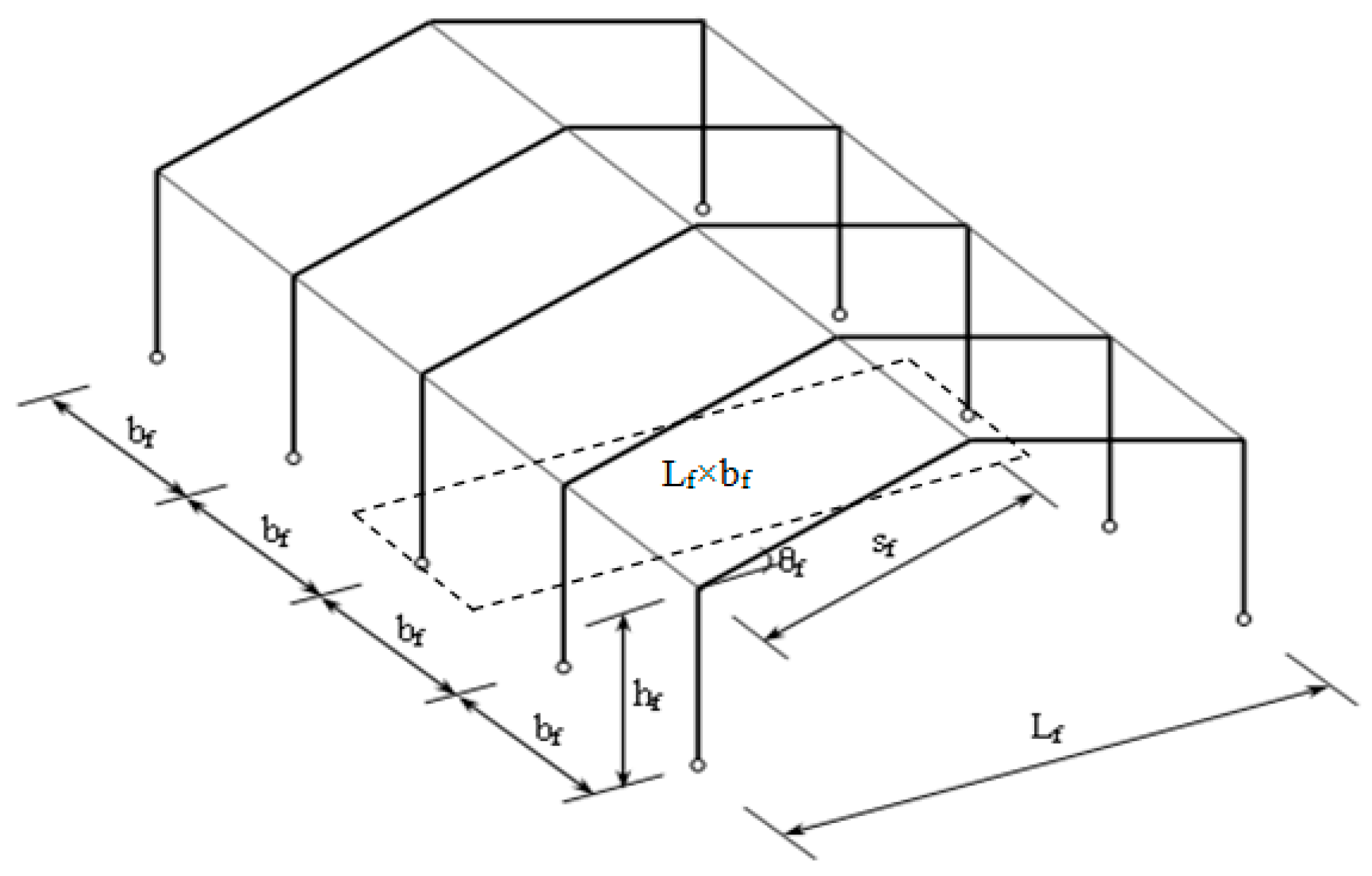
2. General Description of Long-Span Cold-Formed Steel Portal Frames

The parameters adopted for the proposed portal frame are as follows: span of frame Lf, height to eaves hf, pitch of frame θf and bay spacing bf (see Figure 2). For long-span frame considered in this study, the framing systems were composed of back-to-back channels (BBC) used for the columns, rafters and knee braces. Column bases are pinned into its foundations.
Details of eaves joint [1] formed through plane brackets bolted between the webs of the channel-sections is shown in Figure 3. For eaves joints, only four bolts are used for each connection between the brackets and the members. For the apex joint, nine bolts are assumed to be used for the connection between bracket and rafter (see Figure 4).
The Benchmark Frame considered in this paper has a span of 13.6 m, height to eaves of 5.4 m, pitch of 10° and frame spacing (bf) of 3.6 m. Also, the layout of knee brace is formed with a distance of 1.36 m from the top of column and knee angle of 50° [1]. The primary members are laterally restrained by purlins and side rails with the spacing of 1.3 m. It is worth noting that out-of-plane restraints were applied to the rafters at the locations of the purlin brackets and the center of the apex bracket, to prevent lateral deflection.
Through a full-scale experimental test of CFS long span portal frame, it was shown that the true spring stiffness of the eaves connection has minimal impact, owing to effective triangle formed between knee, column and rafter at the eaves connection [1]. Therefore, column to rafter, knee to column and knee to rafter connections can be considered as ideally pinned joints (Figure 5).
For the apex joint of CFS portal frames, owing to the bolt holes elongate under load leading to a remarkable rotation in the joints [24,25]. Such joints therefore cannot be processed as rigid. Also, it was observed when the bolt group resists an external moment it rotates around the center of the bolt group because of the symmetrical configuration of the bolted joints [26,27,28]. Through the full-scale test of CFS portal frame, it is worth noting that the assumption is reasonable with sufficient accuracy. The stiffness of the bolted joints used for CFS portal frame can be idealized by a rotational spring at the center of rotation of each bolt group [24], as shown in Equation (1).
k B = 3 2 ( a ar 2 + b ar 2 ) k b
where aar is the length of bolt group; bar is the width of bolt group; kb (kN/mm) is bolt hole elongation stiffness depending on the web thickness of CFS channel sections [7]. The distance from intersection of the members to the center of rotation of each bolt-group is referred to as the effective length of the connection (Figure 6).
The variation of vertical load against vertical deflection at the apex obtained from experimental test and beam idealization are shown in Figure 7. As can be seen, the deflection due to misalignment of the bolt holes was offset along the deflection axis and so enables the experimental and numerical results to be compared at loads when all the bolt shanks are in full bearing contact against the bolt holes. It also can be seen that the results obtained from elastic frame analysis is similar with the experimental results in the elastic region [6,24].

3. Design of Benchmark Frame Following Eurocode 3

Benchmark frame is designed under the permanent load (G) of 0.15 kN/m2 and variable load (Q) of 0.6 kN/m2. Variable and permanent actions for ultimate load combination in accordance with Eurocode 3 [29] are factored as follows:
ULS = 1.35 G + 1.5 Q + EHF
where:
  • ULS is the ultimate limit state
  • EHF is the equivalent horizontal forces
The magnitude of the equivalent horizontal forces is based on initial sway imperfection of frame. It is simply assumed that the notional horizontal load acts at the top of the column according to Eurocode 3. Also, it should be noted that only a vertical load case is considered in this study, which is the same as loading used for the full-scale experimental test of Benchmark Frame.
In this study, second-order elastic analysis is used for frame analysis, using the finite element program ANSYS. BEAM3 element was used for the columns and rafters; LINK10 was used to idealize the knee brace member. For the semi-rigidity of the joints, a rotational spring element of zero size connected with two coincident nodes at the joint positions (COMBIN40) was used [30].
The normalized forms of the design constraints for checking frame members following Eurocode 3 [31] are expressed as follows:
g 1 = N Ed N c , Rd 1 0
g 2 = N Ed N b , Rd 1 0
g 3 = N Ed N c , Rd + M y , Ed M cy , Rd 1 0
g 4 = M Ed M c , Rd + F Ed R w , Rd 1.25 0
g 5 = M Ed M b , Rd 1 0
g 6 = ( N Ed N b , Rd ) 0.8 + ( M Ed M b , Rd ) 0.8 1 0
where g1 is constraint for sectional buckling, namely, local or distortional buckling of section; g2 is constraint for lateral buckling of members; g3 is constraint for combined axial compression and bending moment; g4 is constraint for crushing at the frame joints; g5 is constraint for lateral torsional buckling of bending members; g6 is constraint for buckling of member in both bending and compression.

4. Design Optimization Model

The objective of the design optimization is to minimize the weight of the portal frame per unit floor area for one full bay (see Figure 2), whilst satisfying the design constraints as mentioned in Section 3. It should be noted that the unit weight depends on the frame spacing, frame geometry, cross-section sizes of members and sizes apex bracket and can be expressed as:
W = 1 L f b f [ i = 1 m c i l i + w br c br ]
where
  • W is the weight of the frame per square meter of floor area
  • wi are the weights per unit length of cold-formed steel sections for frame members
  • li are the lengths of cold-formed steel frame members
  • m is the number of structural members in the portal frame
  • wbr is the total weight of the brackets
For this optimization model, decision variables consist of both discrete and continuous ones. Optimum section of columns, rafters and knee braces respectively, is processed as discrete variables. Continuous variables are roof pitch, frame spacing, knee configuration and apex bracket size. Details of design variables for this design optimization are categorized into four groups, i.e., G1 to G4, as follows:
G1.
The size of cross sections designated for column, rafter and knee brace members
G2.
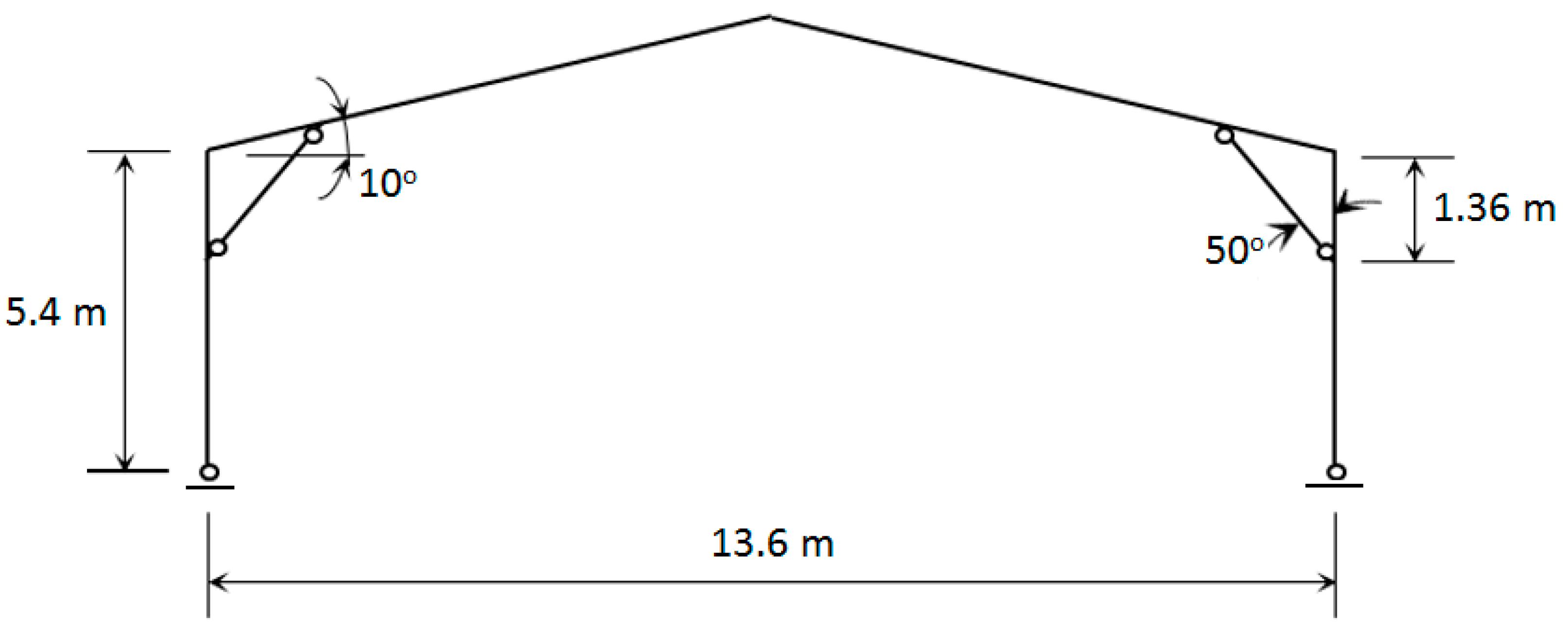
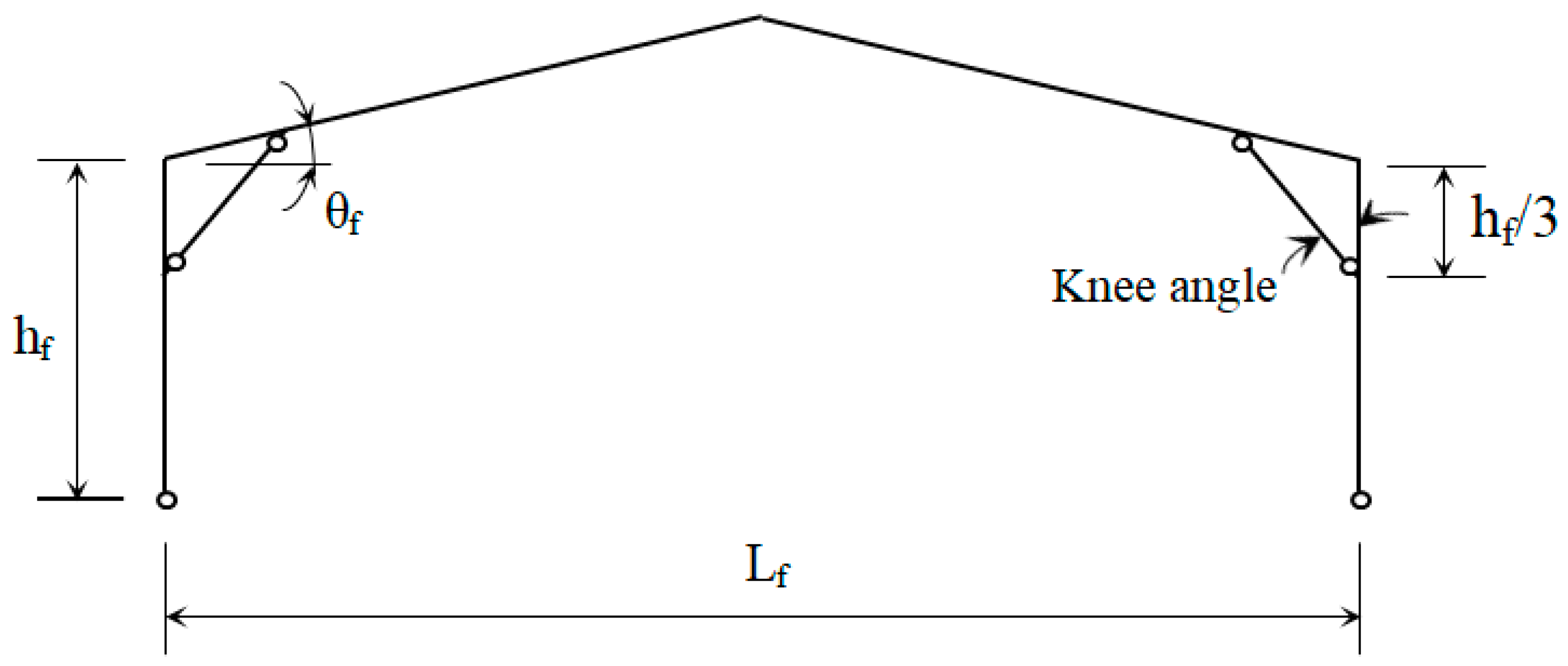
Dimensions of knee brace joints: knee angle and position of knee brace connection from the top of column (vert. dist.), as shown in Figure 5.
G3.
Topology of framing system: frame spacing (bay) and rafter pitch
G4.
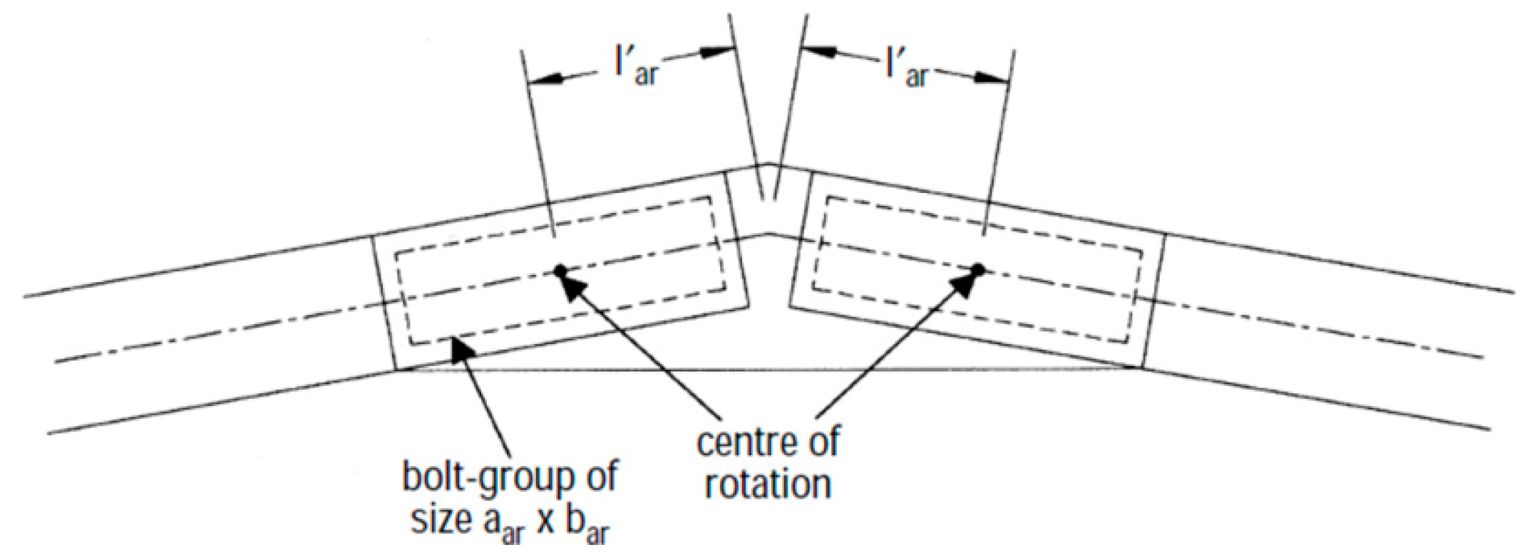
Length of bolt-group of apex joint
As can be seen, there are total eight decision variables that need to be optimized for the minimum unit weight of Benchmark Frame. Three design variables in Group 1 (G1) are chosen from the list of commercial CFS channel sections as shown in Table 1. It is worth mentioning that back-to-back channel section (BBC), as shown in Figure 4, is used for frame members owing to long-span frame, as well as eliminating the effect of eccentricity happened for the case of the single channel sections.
For practical design of frame, parameters of G2–G4 variables are set in predefined range. Specifically, vert.dist. dimension is varied in the range of [column-height/10, column-height/3]; knee angle is varied in the range of [5°, 70°]. Frame spacing is set in the range of [2 m, 6 m] for an economical design of purlins and side rails. Roof pitch is varied from [6°, 30°]. Bolt-group length is varied in the range of [0.14 m to 1.00 m]. To provide a high lateral stiffness of bracket, thickness of 4 mm is assumed to be applied for the eaves and apex brackets. For the preliminary design of Benchmark Frame for experimental test, the knee angle is of 50°; position of knee brace connection from the top of column (vert.dist.) is of 1.36 m; pitch is of 10°, frame spacing bf is of 3.6 m (see Figure 2).
Due to the high nonlinearity of the problem, a real-coded genetic algorithm (RC-GA) was adopted. This population-based algorithm generates solutions by carrying out binary tournament selection, SBX crossover and polynomial mutation for the evolutionary process [22]. It is worth noting that the binary tournament selection can efficiently preserve the population diversity, which increases the exploration component of the algorithm. The genetic operators of RC-GA, i.e., selection, crossover and mutation, are directly applied to the decision variables without coding and decoding. This is a convenient characteristic as compared against binary GAs.
In this paper, the effect of niching strategy on maintaining the population diversity is combined with RC-GA to increase the robustness and reliability of proposed algorithm in searching for the optimum solution. Niching strategy is applied for selection and reproduction operators. Niching is carried out through comparing a normalized Euclidean distance, known as niching radius [22]. If distance smaller than a pre-defined distance, or in the same niche, they are allowed to become mating partners. If the randomly chosen solutions satisfy the constraint of the niching radius, they then are compared with fitness values for the tournament selection operator. Therefore, only solutions in same region (or niche) are considered. GA flowchart for design optimization of Benchmark Frame is shown in Figure 8.

5. Fitness Function

To handle the design constraints for single objective optimization using genetic algorithms, penalty functions are often used for transforming a constrained problem to an unconstrained one. In this study, a novel dynamics penalty strategy is proposed, in which descending penalty value is added into the objective function to evaluate the fitness of individuals in the population as generation progresses.
CVP i = K . g i G e n 0.5
where CVPi is the violated penalty for the ith design constraint; K is scale factor of 100; gi is the violated constraint; Gen is the current generation.
For making the comparison, this study also carries out two typical penalty methods, namely, non-scale factor strategy applying for tournament selection operator, where two solutions are compared at a time and the following criteria are carried out: (a). any feasible solution is preferred to any infeasible solution; (b). among two feasible solutions, the one having better objective function value is preferred; (c). among two infeasible solutions, the one having smaller constraint violation is preferred [22]. It should be noted that penalty parameters are not needed because in any of these three settings, solutions are not compared in terms of both objective function and constraint violation information. Second penalty strategy considered in this paper uses ascending penalized value as generation progresses.
CVP i = ( 0.5 Gen ) 2 × 10 g i
This method will define the fitness function to assess the quality of the solutions throughout evolutionary process of genetic algorithms. The adopted fitness function (F) has a form as follows:
F = W + i = 1 6 CVP i

6. Design Examples

6.1. Optimum Design of Benchmark Frame with Full Rigidity for Apex Joint

In this section, Benchmark Frame is firstly optimized whilst decision variables of groups G2 and G3 are fixed. With rigid joint assumption, design variable for bolt-group length of apex connection is excluded in this example. The real-coded GA is applied for searching the optimum section designated for columns, rafters and knee member to minimize the unit weight of Benchmark Frame. The genetic parameters used for optimization process are as follows: number of generations = 50; niching radius = 0.3; mutation probability = 0.1; crossover probability = 0.9. The initial populations were generated randomly with 40 individuals. The optimization algorithm was executed 10 times for each penalty function strategy. It was observed that for all of three penalty methods, the standard deviations of the lightest weight achieved, based on 10 optimization runs, are consistently small with the minimum weight obtained for each run near the best one. The lightest weight of frame per unit area on the floor of building for one full bay obtained is of 7.76 kg/m2. The optimum section designated for frame members is BBC24030, BBC24016 and BBC14014 for column, rafter and knee brace members respectively (Table 2). Design constraint for buckling of column member in both bending and compression is critical and governed the optimum design, i.e., g6 = −0.01.
Next, the effect of knee brace configuration on the design optimization of Benchmark Frame is investigated. The knee angle is optimized, whilst fixing the position of knee brace connection from the top of column (vert.dist) of 1.36 m. The real-coded GA is applied using the same genetic parameters as used in previous example. It is worth mentioning that with such addition of extra design variable, the dimension of the search space could grow exponentially. To enhance the searching performance of proposed algorithm, a number of trials for determining the population size for optimization process are carried out for each penalty method. For penalty strategy with non-scale factor, a population of 120 is found for the best performance of real-coded GA in associated with a reasonable processing time. It was observed that the time of searching the optimum solution is around 4.5 h after carrying out 15,000 function evaluations. It was experienced that evolutionary process slowly converged into the optimum solution. For the method using ascending penalty strategy, it is observed that the reliability and robustness of optimization algorithm is low with standard deviations is quite large. This is because the best factor for this penalty strategy is not straightforward to determine, which causes a premature convergence. For the proposed method with descending penalty strategy, it was found that only small population size of 60 can effectively search for the optimum solution within 2 h that is approximate 50% faster in terms of computational time compared to previous methods. The reliability was obtained with a small standard deviation of 0.066 obtained after 10 runs. The convergence history of typical GA runs in associated with each penalty strategy is shown in Figure 9. As can be seen, the minimum unit weight for this design optimization is 7.61 kg/m2. Detail of optimum result obtained from this design optimization is also shown in Table 2.
As can be seen in Table 2, the optimum knee angle is of 37.4°, which is smaller than that of preliminary design, i.e., 50°. Since bending moment on rafters is transferred to column through knee braces, a small knee angle can reduce the maximum bending moment on the column, whilst increasing hogging moment at the knee brace joint on rafter. For such response of bending moment through the variation of knee brace configuration, a smaller cross section size was designated for column members, i.e., BBC24025 and larger section was applied for rafters, i.e., BBC24020 (Table 2). It can be seen that the effect of knee angle only shows a slight decrease on the minimum unit weight of Benchmark Frame. Design constraint for buckling of column and rafter member in both bending and compression is critical and governed the optimum design, i.e., g6 = 0.
For the case of design accounting for the influence of both vert.dist parameter of knee joint position on column and knee angle. The optimum solution indicated that a small knee brace angle of 38.2° in associated with large distance for position of knee brace connection from the top of column of 1.79 m can reduce the unit weight of Benchmark Frame around 4.12%. Interestingly, when all decision variables are varied, the minimum unit weight remarkably decreases approximately 19.72% as compared with the preliminary design. It should be noted that the remaining design cases used a population size of 80 for the evolutionary process using proposed penalty method. As expected, the reliability and robustness were obtained with small standard deviation obtained after 10 GA runs.

6.2. Optimum Design of Benchmark Frame Accounting for Semi-Rigidity of Apex Joint

The process of structural analysis of Benchmark Frame with full rigidity at apex joint experienced that bending moment is considerably distributed to apex joint owing to low stiffness with the assumption of pinned joints being used for column to rafter, knee to column and knee to rafter connections at eaves of portal frame. It is worth mentioning that realistic response of apex joint is semi-rigid in associated with finite connection-length. This behavior therefore has significant influence on bending moment redistribution from apex joint to eaves joints on column and rafter. In this section, the optimum design of Benchmark Frame including the effect of semi-rigid joint is considered.
There are eight design variables for this optimization, namely, three discrete variables for column, rafter and knee cross sections (G1), two continuous variables for vert.dist. parameter and knee angle (G2), two continuous variables for building topology (G3) and bolt-group length of apex joint (G4). Since the reliability and robustness of real-coded GA combining with proposed penalty function method has been shown in previous examples, optimum design of Benchmark Frame is carried out 10 GA runs with a population of 80 randomly generated. The genetic parameters used for optimization process are also as follows: number of generations = 50; niching radius = 0.3; mutation probability = 0.1; crossover probability = 0.9.
It was observed that the history of evolutionary process converged into the optimum solution within 3200 function evaluations (Figure 10). As expected, the standard deviations of the lightest weight achieved, based on 10 optimization runs are consistently small, i.e., 0.085, with the minimum weight obtained for each run near the best one of 6.30 kg/m2. Design constraint for buckling of column and rafter member in both bending and compression is critical and governed the optimum design, i.e., g6 = −0.011.
The detailed result showed that optimum cross-section designated to frame members and frame spacing are the same as the frame design with rigid joint at apex. The influence of semi-rigidity at apex joint shows the effect on knee configuration and pitch. The optimum pitch of 11.84° was obtained that could reduce the distance of knee joint on column from the top, i.e., 1.46 m, in associated with an optimum knee angle of 42.5°. The advance of the design procedure is that the detail of apex joint, i.e., bolt-group length of 0.406 m, was obtained and the apex stiffness is 68.34 kNm/deg, as calculated from Equation (1). It was observed from experimental result about the relationship between maximum bending moment on column and apex stiffness [1], that the joint detail at apex of CFS portal frame obtained from design optimization almost behaves as rigid joint. This resulted in the same optimum cross-section designated for frame members as those used for Benchmark Frame with rigid joint at apex.

7. Conclusions

The optimum design of long-span CFS portal frame having span of 13.6 m and column height of 5.4 m, known as Benchmark Frame, was carried out accounting for the influence of knee brace configuration. Eurocode 3 was applied for conducting the member and joint checks. The real-coded niching GA in associated with a novel penalty method to handle constraints of the design optimization of Benchmark Frame under the action of gravity loads. Through a number of GA runs, it was shown that the proposed constraint handling procedure with descending penalty values as generation progressed can effectively search for the optimum solution. The effective computational time, which is approximate 50% faster than methods being popularly used in literature, indicates capability of proposed optimum routine for practical application.
The effect of knee brace configuration combining with topology of framing system was investigated through four design cases, which the saving of material used for Benchmark Frame up to 19.72% as compared against experimental frame. The reasonable location of knee brace joint on the column should be one third of the eaves height from the top and knee angle is approximate 42°. For a future research, this result should be verified against the full-scale experiment, as well as 3-D modeling with shell elements to further investigate the realistic structural behavior of such long-span CFS portal frame. Also, the influence of horizontal forces, i.e., seismic or wind loads on the optimum configuration of knee brace joints and structural performance of CFS frame should be considered.

Author Contributions

Phan conceived and designed the optimization. The optimization algorithm was scripted and performed by Thanh Duoc Phan and Meheron Selowara Joo prepared the manuscript based on the guidance and feedback from A/P. James B. P. Lim and Hieng-Ho Lau. All authors have checked the optimization outcome, read and approved the final manuscript.

Conflicts of Interest

The authors declare no conflict of interest.

References

  1. Blum, H.B.; Rasmussen, K.J.R. Experiments on long-span cold-formed steel portal frames composed of double channels. In Proceedings of the 7th International Conference on Coupled Instabilities in Metal Structures, Baltimore, MD, USA, 7–8 November 2016. [Google Scholar]
  2. Dundu, M. Design approach of cold-formed steel portal frames. Int. J. Steel Struct. 2011, 11, 259–273. [Google Scholar] [CrossRef]
  3. Schafer, B.W. Local, Distortional and Euler Buckling of Thin-Walled Columns. J. Struct. Eng. 2002, 128, 289–299. [Google Scholar] [CrossRef]
  4. Orlando, M.; Lavacchini, G.; Ortolani, B.; Spinelli, P. Experimental capacity of perforated cold-formed steel open sections under compression and bending. Steel Compos. Struct. 2017, 24, 201–211. [Google Scholar]
  5. Bertocci, L.; Comparini, D.; Lavacchini, G.; Orlando, M.; Salvatori, L.; Spinelli, P. Experimental, numerical and regulatory P-Mx-My domains for cold-formed perforated steel uprights of pallet-racks. Thine-Walled Struct. 2017, 119, 151–165. [Google Scholar] [CrossRef]
  6. Lim, J.B.P.; Nethercot, D.A. Finite element idealization of a cold-formed steel portal frame. J. Struct. Eng. 2004, 130, 78–94. [Google Scholar] [CrossRef]
  7. Phan, D.T.; Lim, J.B.P.; Tanyimboh, T.T.; Sha, W. Effect of joints having semi-rigidity and finite connection-length in optimal design of cold-formed steel portal frames. Int. J. Steel Struct. 2017, 17, 427–442. [Google Scholar] [CrossRef]
  8. Toropov, V.V.; Mahfouz, S.Y. Design optimization of structural steelwork using genetic algorithm, FEM and a system of design rules. Eng. Comput. 2001, 18, 437–459. [Google Scholar] [CrossRef]
  9. Saka, M.P. Optimum design of pitched roof steel frames with haunched rafters by genetic algorithm. Comput. Struct. 2003, 81, 1967–1978. [Google Scholar] [CrossRef]
  10. Issa, H.K.; Mohammad, F.A. Effect of mutation schemes on convergence to optimum design of steel frames. J. Constr. Steel Res. 2010, 66, 954–961. [Google Scholar] [CrossRef]
  11. Phan, D.T.; Lim, J.B.P.; Tanyimboh, T.T.; Lawson, R.M.; Martin, S.; Sha, W. Effect of serviceability limit on optimal design of steel portal frames. J. Constr. Steel Res. 2013, 86, 74–84. [Google Scholar] [CrossRef] [Green Version]
  12. McKinstray, R.; Lim, J.B.P.; Tanyimboh, T.T.; Sha, W.; Phan, D.T. Optimal design of long-span steel portal frames using fabricated beams to Eurocode. J. Constr. Steel Res. 2015, 104, 104–114. [Google Scholar] [CrossRef] [Green Version]
  13. Phan, D.T.; Lim, J.B.P.; Sha, W.; Siew, C.; Tanyimboh, T.T.; Issa, K.H.; Mohammad, F.A. Design optimization of cold-formed steel portal frames taking into account the effect of topography. Eng. Optim. 2013, 45, 415–433. [Google Scholar] [CrossRef]
  14. Autralian/New Zealand StandardTM. Cold-Formed Steel Structures; AS/NZS4600:2005; Standards Australia: Sydney, Australia, 2005. Available online: https://www.saiglobal.com/PDFTemp/Previews/OSH/as/as4000/4600/4600-2005.pdf (accessed on 10 December 2017).
  15. Wrzesien, A.M.; Phan, D.T.; Lim, J.B.P.; Lau, H.H.; Hajirasouliha, I.; Tan, C.S. Effect of stressed-skin action on optimal design of cold-formed steel square and rectangular-shaped portal frame buildings. Int. J. Steel Struct. 2016, 16, 299–307. [Google Scholar] [CrossRef]
  16. Phan, D.T.; Lim, J.B.P.; Tanyimboh, T.T.; Wrzesien, A.M.; Sha, W.; Lawson, R.M. Optimal design of cold-formed steel portal frames for stressed-skin action using genetic algorithm. Eng. Struct. 2015, 93, 36–49. [Google Scholar] [CrossRef] [Green Version]
  17. Phan, D.T.; Wrzesien, A.M.; Lim, J.B.P.; Hajirasouliha, I. Effects of Stressed-Skin Action on Optimal Design of a Cold-Formed Steel Portal Framing System. In Proceedings of the 22nd International Specialty Conference in Cold-Formed Steel Structures, Saint Louis, MO, USA, 5–6 November 2014. [Google Scholar]
  18. British Standard. BS 5950–5: Structural Use of Steelworks in Building. Part 5. Code of Practice for Design of Cold-Formed Thin Gauge Sections; British Standards Institution: London, UK, 1998; Available online: https://shop.bsigroup.com/ProductDetail/?pid=000000000030155279 (accessed on 10 December 2017).
  19. Yeniay, O. Penalty function methods for constrained optimization with genetic algorithms. Math. Comput. Appl. 2005, 10, 45–56. [Google Scholar] [CrossRef]
  20. Deb, K. An efficient constraint handling method for genetic algorithms. Comput. Methods Appl. Mech. Eng. 2000, 186, 311–338. [Google Scholar] [CrossRef]
  21. Pezeshk, S.; Camp, C.V.; Chen, D. Design of nonlinear framed structures using genetic optimization. J. Struct. Eng. 2000, 126, 382–388. [Google Scholar] [CrossRef]
  22. Deb, K. Multi-Objective Optimization Using Evolutionary Algorithms; John Wiley & Sons: Chichester, UK, 2001. [Google Scholar]
  23. Erbatur, F.; Hasançebi, O.; Tutuncu, I.; Kiliç, H. Optimal design of planar and space structures with genetic algorithms. Comput. Struct. 2000, 75, 209–224. [Google Scholar] [CrossRef]
  24. Lim, J.B.P.; Nethercot, D.A. Stiffness prediction for bolted moment-connections between cold-formed steel members. J. Constr. Steel Res. 2004, 60, 85–107. [Google Scholar] [CrossRef]
  25. Wrzesien, A.M.; Lim, J.B.P.; Nethercot, D.A. Optimum Joint Detail for a General Cold-Formed Steel Portal Frame. Adv. Struct. Eng. 2012, 15, 623–640. [Google Scholar] [CrossRef]
  26. Kulak, G.L.; Fisher, J.W.; Struik, J.H.A. Guide to Design Criteria for Bolted and Riveted Joints, 2nd ed.; John Wiley & Sons: New York, NY, USA, 1987. [Google Scholar]
  27. Davies, J.M. Connections for cold-formed steelwork. In Design of Cold-Formed Steel Members; Rhodes, J., Ed.; Elsevier Applied Science: London, UK; New York, NY, USA, 1991. [Google Scholar]
  28. Zandanfarrokh, F.; Bryan, E.R. Testing and design of bolted connections in cold-formed steel sections. In Proceedings of the 11th International Specialty Conference on Cold-Formed Steel Structures, Saint Louis, MO, USA, 20–21 October 1992; pp. 625–662. [Google Scholar]
  29. British Standard BS EN 1993-1-1. Eurocode 3: Design of Steel Structures: Part 1—General Rules and Rules for Buildings; Committee European de Normalization: Brussels, Belgium, 2005; ISBN 0580460789. Available online: http://eurocodes.jrc.ec.europa.eu/showpage.php?id=133 (accessed on 11 December 2017).
  30. SAS IP, Inc. ANSYS: Release 14.5. 2012. Available online: http://www.ansys.com (accessed on 11 December 2017).
  31. Dubina, D.; Ungureanu, V.; Landolfo, R. Design of Cold-Formed Steel Structures; European Convention for Constructional Steelwork: Timisoara, Romania, 2012; ISBN 978-3-433-02979-4. Available online: http://as.wiley.com/WileyCDA/WileyTitle/productCd-3433029792.html (accessed on 11 December 2017).
Figure 1. Geometry of CFS Benchmark Frame with knee brace joints.
Technologies 05 00081 g001
Figure 2. Parameters used to define general portal framing system.
Technologies 05 00081 g002
Figure 3. Knee brace joint at eaves.
Technologies 05 00081 g003
Figure 4. Details of apex joint.
Technologies 05 00081 g004
Figure 5. General diagram of knee brace joint configuration.
Technologies 05 00081 g005
Figure 6. Effective length of apex connection.
Technologies 05 00081 g006
Figure 7. Variation of vertical load against apex deflection [6].
Technologies 05 00081 g007
Figure 8. Flowchart of real-coded GA [11].
Technologies 05 00081 g008
Figure 9. Convergence history of GA runs with three penalty strategies.
Technologies 05 00081 g009
Figure 10. Convergence history of design optimization for frame having semi-rigidity at apex joint.
Technologies 05 00081 g010
Table 1. The list of CFS channel sections used for frame members.
No.SectionDepth (mm)Width (mm)Lip (mm)Aeff (mm2)Ieff (mm4)kb (kN/mm)
1C140141406213204.04011,082,7797.86
2C140151406213232.19361,201,0118.33
3C140161406213261.37471,321,4488.79
4C140181406213322.5291,563,5769.67
5C140201406213386.9391,809,19810.53
6C170141706213203.79551,626,8037.86
7C170151706213229.73691,806,8308.33
8C170161706213258.33041,990,0878.79
9C170181706213320.13872,355,9609.67
10C170201706213385.45792,729,07610.53
11C170251706213547.95653,638,58212.5
12C200142007015211.06292,404,9607.86
13C200152007015238.18626712288.33
14C200162007015266.581729509718.79
15C200182007015329.20353,524,8259.67
16C200202007015399.06594,101,79510.53
17C200252007015583.52745,555,00812.50
18C240152407417244.48944,054,7438.33
19C240162407417273.78714,486,9428.79
20C240182407417336.77475,374,9589.67
21C240202407417409.55796,283,74710.53
22C240252407417607.87168,585,41512.50
23C240302407417806.45161.08 × 10714.28
24C300203009519418.551.07 × 10710.53
25C300253009519617.13341.50 × 10712.50
26C300303009519862.10161.95 × 10714.28
Table 2. Optimum design of Benchmark Frame with rigid joint at apex.
Design OptionsG1 (BBC Configuration)G2G3Weight
ColumnRafterKneeVert.dist.Knee AngleBayPitchkg/m2
G1: varied
G2,G3: fixed
C24030C24016C140141.36 m50°3.6 m10°7.76
G1,G2 b: varied
G2 a,G3: fixed
C24025C24020C140141.36 m37.4°3.6 m10°7.61
G1,G2: varied
G3: fixed
C24025C24018C140141.79 m38.2°3.6 m10°7.44
All: variedC30030C24025C140141.75 m41.2°6.0 m7.4°6.23
Notes: G2 a is for position of knee brace connection from the top of column; G2 b is for knee angle.

