Article

Dry Separation of Palm Kernel and Palm Shell Using a Novel Five-Stage Winnowing Column System

1
Milling & Processing Unit, Engineering & Processing Research Division, Malaysian Palm Oil Board, Ministry of Plantation Industries & Commodities, 6, Persiaran Institusi, Bandar Baru Bangi, 43000 Kajang, Selangor, Malaysia
2
Biomass Technology Unit, Engineering & Processing Research Division, Malaysian Palm Oil Board, Ministry of Plantation Industries & Commodities, 6, Persiaran Institusi, Bandar Baru Bangi, 43000 Kajang, Selangor, Malaysia
3
Director General’s Office, Malaysian Palm Oil Board, Ministry of Plantation Industries & Commodities, 6, Persiaran Institusi, Bandar Baru Bangi, 43000 Kajang, Selangor, Malaysia
4
Energy & Environment Unit, Engineering & Processing Research Division, Malaysian Palm Oil Board, Ministry of Plantation Industries & Commodities, 6, Persiaran Institusi, Bandar Baru Bangi, 43000 Kajang, Selangor, Malaysia
*
Author to whom correspondence should be addressed.
Technologies 2016, 4(2), 13; https://doi.org/10.3390/technologies4020013
Submission received: 26 February 2016 / Revised: 11 April 2016 / Accepted: 13 April 2016 / Published: 20 April 2016

Abstract

:
The conventional separation system for the recovery of palm kernel from its palm shell–kernel mixture using water as process media generates a considerable amount of waste effluent that harms the environment. The aim of this study is to develop a dry separation process for the recovery of palm kernel by using winnowing columns. A commercial system consisting of a series of five winnowing columns was developed and installed at a local palm oil mill. The system parameters, including column height, blower capacity, airflow rate and mesh screen size for shell removal, were studied and optimized to ensure good separation of kernel and shell in the column to enable collection of different sizes of kernel and shell at each column outlet. The performance of the separation process was evaluated in terms of its kernel losses, dirt content and kernel recovery rate. The average kernel losses based on oil palm fresh fruit bunches processed were found to vary from 0.11 to 0.30 wt %, with most of the values obtained being below the targeted limit of 0.30 wt %. The dirt content was in the range 4.56–6.03 wt %, which was mostly below the targeted limit of 5.5 wt %. The kernel recovery rate was in the range 5.69–6.89 wt %, with most of the values achieving the minimum targeted limit of 6.00 wt %. The system operates under completely dry conditions and, therefore, produces zero waste effluent.

1. Introduction

Palm fruit of oil palm (Elaeis guineensis) contains mesocarp and palm kernel, the latter contributing 45–48 wt % of the total fruit [1]. The kernel contains ca. 45%–50% kernel oil, which is rich in lauric acid C12 (45%–52%), myristic acid C14 (15%–17%) and oleic acid C18:1 (13%–19%) [2]. Palm kernel oil is widely used in food applications, including the production of margarine, confectionary fat, shortening and vegetable ghee [3,4,5]. Furthermore, research and development have made it possible for the palm kernel oil to be used in nonfood lipid sources for the production of bioresin, lubricants, chelating agents for metal extraction and other important chemicals [6,7].
In palm oil mill (POM), oil palm fresh fruit bunches (FFB) are processed to produce crude palm oil (CPO). Palm fiber, empty fruit bunches, sludge, decanter cake and palm nuts are produced as byproducts. The nut is usually collected after the removal of the mesocarp fiber, and the kernel inside the nut is separated from the nut’s shell for subsequent oil extraction [8,9]. The shell can be utilized as fuel, used in the production of activated carbon for waste water treatment, and used in analytical applications [10,11,12]. The production of palm kernel starts with the cracking of palm nuts using a palm nutcracker to produce a cracked mixture of palm kernel and palm shell [13]. Subsequently, the separation of shell and kernel from the cracked mixture is performed using a combination of dry and wet separation systems.
The existing system commonly adopted at a POM in Malaysia separates ca. 20 wt % light shell fragments using a dry separation winnowing column, while ca. 80 wt % heavy shell and kernel are separated using wet separation systems either by claybath or hydrocyclone [14]. The wet separation process of a cracked mixture is based on the differential specific gravities of shell and kernel [15]. Both the wet separation systems use water for performing the desired separation and are not considered environmentally friendly due to the generation of a large volume of waste effluent [16]. These processes produce wet kernel that requires a drying process prior to storage and therefore requires additional energy for the heat transfer. POMs in Malaysia currently employ the wet separation system for the separation of kernel from the shell. The drawbacks associated with the wet process were successfully eliminated in the current system, which is based on a dry technique. A few attempts have been made to introduce a dry technique for the separation of the kernel from its cracked mixture on a commercial and pilot scale. One method in particular uses an experimental rotary separator, as reported by Olasumboye and Koya [17]. Though the objective of achieving dry separation was a success, the study also reported a significant amount of kernel losses, ranging from 4% to 5%, due to attachment to the shell during the separation process [17].
The cracked mixtures produced by the nutcracker consist of kernel, broken kernel, half-cracked nuts, small shell and large shell [13]. The separation process of the shell and kernel fragments depends on the physical characteristics of the components of the mixture. If the fragments are large, the separation process is simple. The separation process becomes more complex when there are different sizes and shapes of the shell and kernel [18]. Therefore, a single- or double-stage separating system will not perform efficiently without incurring high kernel loss [14]. There is an urgent need by the industry to improve the conventional separation system as well as to maximize the recovery of dry kernel and shell. Therefore, the aim of this study is to develop an efficient system that can recover the maximum amount of kernel irrespective of their sizes and at the same time produce no waste effluent.
The system developed in this study is designed to separate shell and kernels based on their respective mass and densities. More specifically, the kernel with a greater density compared to other fractions (shell and its fragments) will fall vertically onto the outlet chutes of the columns, while the shell fragments will be blown upwards towards the top opening of each column and then to the cyclone member, which reduces the air velocity to enable the lighter material to settle [14]. Some of the kernel particles with less mass may be blown upwards together with the lightweight shell fragments and discharge as waste material, leading to inefficient separation in the single-stage winnowing column. The purpose of this study, therefore, is to design a separation system consisting of multiple stages of a winnowing column using a suitable airflow rate to extract kernel fragments from the cracked nut mixture without necessarily using a conventional method, such as the claybath or hydrocyclone.

2. Experimental Sections

2.1. Materials

The feeding material for the five-stage winnowing column system was obtained by cracking the palm nuts produced after the milling process. The cracked mixture consists of palm kernel (whole kernel and broken kernel), palm shell and other foreign materials, such as sand and stones. Rolek nutcracker (MPOB & Hur Far, Selangor, Malaysia) was used to crack the palm nuts due to its cracking efficiency of more than 98%, irrespective of the nut size [13].

2.2. Development of the Separation System

In this study, a winnowing column is used for the dry separation of kernel and shell from the nut’s cracked mixture. The system consists of five winnowing columns that can cater about 10 t/h of the cracked nut mixture throughput was developed. In addition to aiming for a totally dry process, it is also designed to improve the separation efficiency of the cracked nut mixture to provide better kernel recovery and shell removal. Figure 1 (left) shows a single-stage winnowing column, whereas Figure 1 (right) shows a dry separation system—the five-stage winnowing column system. Each column is designed with different specifications, viz. airflow rate, column height, inlet level and outlet level, in order to accommodate the feeding materials and to achieve the desired shell and kernel ratio at each outlet point.
The winnowing column is designed with two special features to enhance the separation process. The first feature is that the internal column is equipped with a special device responsible for diverting the direction of the airflow away from the cracked mixture feed flow path, thus creating a laminar airflow through the separating column for better separation of the cracked mixture. The second feature is an adjustable damper for regulating the airflow rate in the separating column by altering the throat diameter of the column. This feature can also be enhanced by column design that uses forced draught instead of induced draught where its airflow rate is powered by an electrical blower and adjusted via the damper located at the ground or at an elevated level as shown in Figure 2. Theoretically, a forced draught puts the system under positive pressure (above atmospheric pressure) and therefore consumes less power compared to an induced draught system that operates under negative pressure (below atmospheric pressure). The forced draught system is due to the placement of the fan at the entry end of the path flow where the outside air is drawn and forced into the system. The throat geometry is easily adjustable on each separating column to cater for the differing characteristics of the cracked nut mixture. The air velocities at each column are optimized by varying the fan speed from the control panel.
Air velocity was measured using an air velocity meter (PCE-AM81, Southampton, UK). The principle of the separation is based on the airflow rate, which was calculated as follows:
V i = v i × A i
where V i is the volumetric airflow rate (m3/min), v i is the air velocity (m/min) and A i is the throat area (m2), for the respective column i .
The separation of shell and kernel in this system works on the principle of the specific gravity differential of the materials in the presence of a high velocity airflow caused by a blower powered by an electric motor. Each stage, as shown in Figure 1 (left), consists of a blower, a winnowing column, a ducting and a cyclone, whereby the separation occurs at each column but the separated material is not necessarily discharged. Circular ducting connects the upper end of the column to the cyclone.
The first column discharges most of the shell after the cyclone unit where the kernel and heavy shell are sent to the second column. The second column discharges most of the kernel and the remaining shells and light kernel are sent to the third column. The light material that goes to the cyclone still remains as a mixture of kernel and shell that will again be subjected to more rigorous separation in the following stages; its quality is not critical. In Stage 5 of the system, the separating column will lift almost all the shells and deposit them in the cyclone due to the reduced height of the cyclone and the ducting. If some small and broken kernels and small shell still remain, these will be discharged from the bottom chute of the fifth separating column. A unit of the shell removal drum (Figure 3) with a mesh size between 14 and 16 mm is placed between the first and second columns to remove any contaminant, specifically thick shell (large and small shell) and uncracked nut from continuing to the next separation column. The removal of these shell fragments at an early stage reduces the load of the cracked mixture to be separated in the subsequent stages.
In all stages of the separation, fan speeds, airflow damper control positions and heights of the cyclone inlet from the top outlet of the separating column are critical because efficient separation of the different components of the cracked mixture rests solely on these settings. These settings were obtained by conducting a number of expensive research trials and as such were safeguarded by means of intellectual property rights and patent.

2.3. Evaluation of System Performance

The five-stage winnowing column system was installed and commercially evaluated at Air Tawar POM, Johor, with a mill capacity of 45 t/h processed FFB. The performance of the separation process was carried out for 8 months, and the system was continuously monitored for another 12 months. Parameters that were closely monitored during the commercial trials were kernel throughput, kernel recovery rate (KER), dirt or shell content in the recovered kernel and kernel losses to ensure meeting the targeted performance as follows: total kernel throughput in the range of 35 to 45 wt %, dirt and shell content in the kernel <5.5 wt %, kernel losses to FFB <0.3 wt % and KER >6.0 wt %. Results were analyzed and compared with the targeted performance of the system and other sister mills in the same region that used a conventional separation system.

2.4. Determination of the Total Dirt Content

We collected 1 kg of the recovered palm kernel (from the final discharge outlet to determine its dirt content. The kernel sample was sorted as whole nut ( d 1 ), half-cracked nuts ( d 2 ), loose shells ( d 3 ) and stones and debris ( d 4 ). Prior to weighing, the whole nuts ( d 1 ) and half-cracked nuts ( d 2 ) were carefully cracked and the shells were weighed separately. Total dirt content was calculated as follows:
D t = [ ( d 1 + d 2 + d 3 + d 1 )   /   P K ] t × 100 %
where D is the total dirt content (wt %), d 1 is the weight of shells of whole nuts (kg), d 2 is the weight of shells of half-cracked nuts (kg), d 3 is the weight of loose shells (kg), d 4 is the weight of stones and debris (kg) and P K is the weight of the palm kernel sample (kg), for a t period of evaluation.

2.5. Determination of Kernel Losses

We collected 1 kg of shell fragment containing mostly shells along with kernel carryover from the shell bunker. The kernel loss was calculated as follows:
K L t = K t × [ ( S t N t ) ] × ( N t F t ) × 100 %
where K L t is the kernel loss over FFB processed (wt %), K t is the weight of kernel carryover in the dirt sample (kg), S t is the weight of shell (kg), N t is the weight of nut (kg) and F t is the weight of FFB (kg), for a t period of evaluation. Shell to nut (S/N) and nut to FFB (N/F) ratios were obtained from actual milling activity.

2.6. Determination of the Kernel Recovery Rate

The KER was calculated by the weight ratio of kernel and fresh fruit bunch as follows:
K E R t = ( K t / F t ) × 100 %
where K E R t is the kernel recovery rate (wt %), K t is the weight of kernel (kg) and F t is the weight of FFB processed (kg), for a t period of evaluation.

2.7. Determination of Nut and Kernel Size Distribution

We collected 2.0 kg of nut and kernel sample from the feeding to the Rolek nutcracker and the kernel discharge outlet, respectively, for size measurement. Both nut and kernel sizes were measured using a perforated metal plate consisting of different sizes, as shown in Figure 4 (left). The horizontal cross-sectional diameter of the nuts and kernels was measured using the plate, and its size distribution was determined.

3. Results and Discussion

3.1. Nut and Kernel Size Distribution

The Rolek nutcracker cracks palm nuts to produce a cracked mixture consisting of more than 35 wt % whole kernel, less than 12 wt % broken kernel, less than 1 wt % uncracked nuts and less than 2 wt % half-cracked nuts. Conventional nutcrackers used at POMs, such as ripple mill and super cracker, often crack both the nuts and the kernel; the cracked mixture then consists of a high broken kernel of ca. 15–25 wt % [19]. Rolek nutcracker differs from other commercial crackers in terms of its principle of operation, which relies on dynamic interactions of adjustable rods varied to break all sizes of nuts without causing high kernel breakage [13,19].
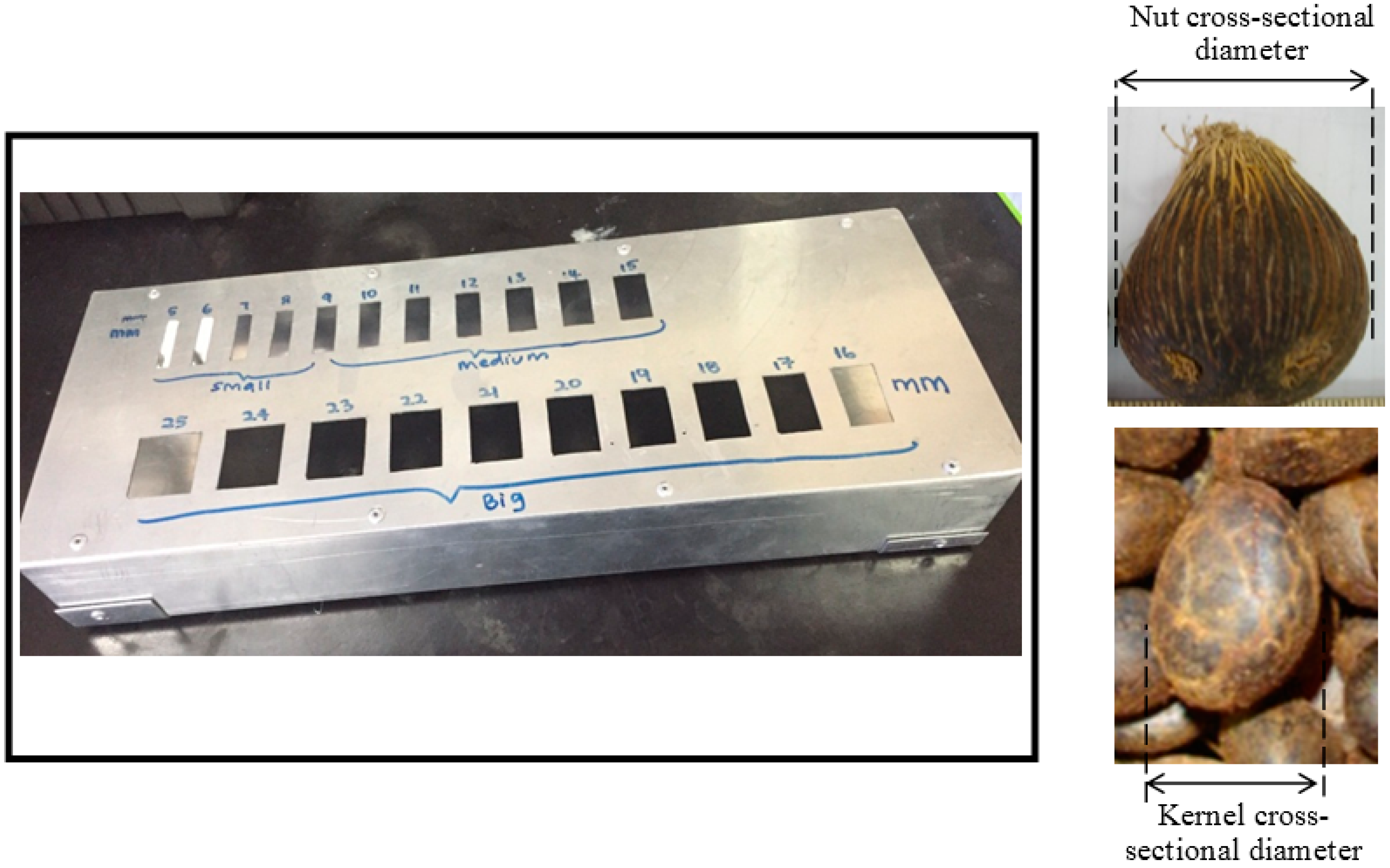
Currently, there is no established method to measure nut and kernel size. Nut and kernel are not perfectly round in shape; thus, the horizontal cross-section of the nut and kernel, as shown in Figure 4 (right), is deemed appropriate to represent the size of the nut and kernel. To determine the size distribution of the collective samples, the sizes are generally grouped into the acceptable range of nut and kernel size, ranging from 5–25 mm. A perforated metal plate consisting of holes with different sizes ranging from 5–25 mm was therefore developed to facilitate size measurement of the collective samples, as shown in Figure 4 (left). This method of measurement is common in POMs in Malaysia but has not been properly documented elsewhere.
Measurement of nut and kernel size distribution prior to cracking was carried out to determine the exact composition of nut type processed in the mill, such as Dura, Pisifera and Tenera. Pisifera is a pollen-type nut, while Dura has a thicker shell and a lower oil content compared to Tenera, which is a hybrid between Pisifera and Dura. Tenera has a high oil content with a thin shell. 
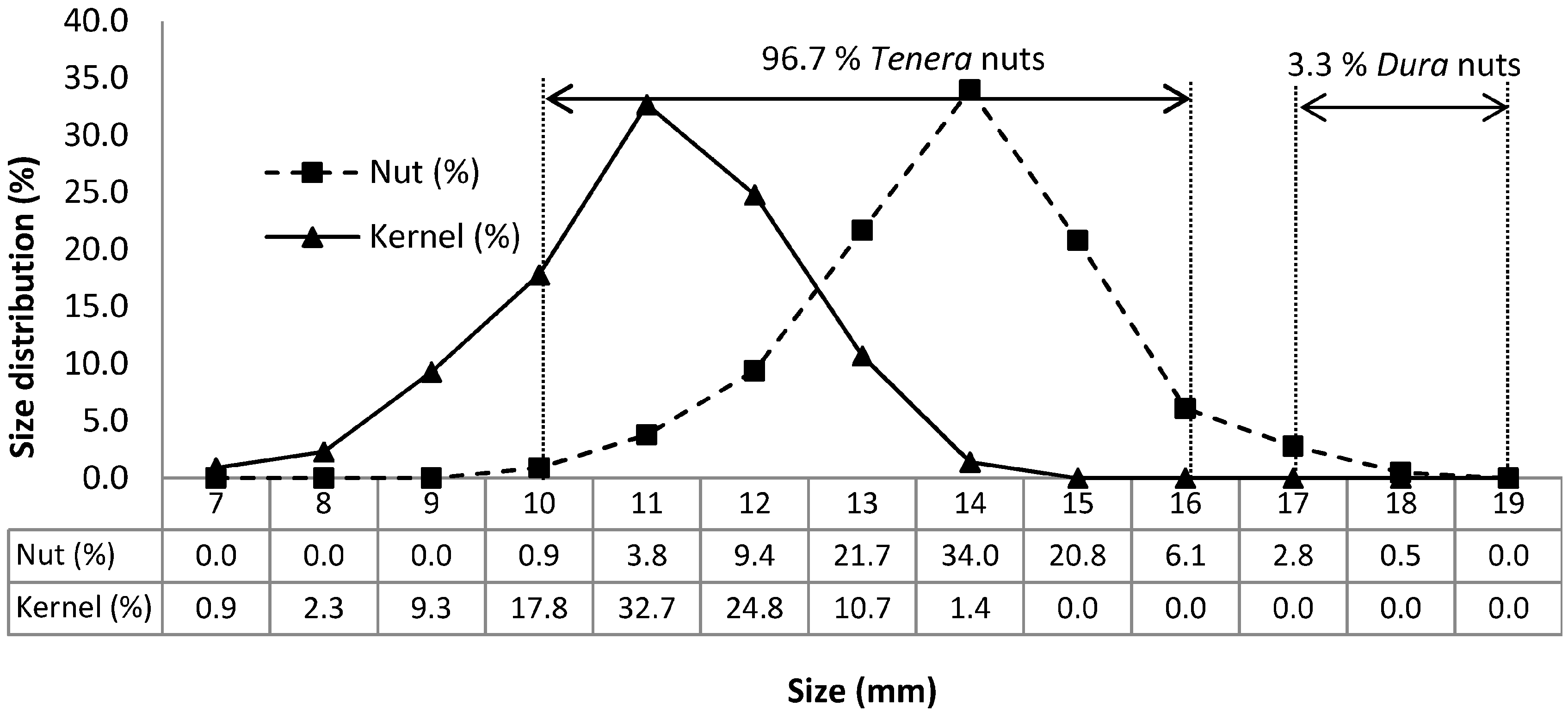
Figure 5 shows nut size distribution prior to cracking and kernel size distribution after separation. It shows that Air Tawar POM processed about 96.7% Tenera nuts and 3.3% Dura nuts. Typical Tenera nuts may be 20 mm or less in length, and Dura nuts may be 20 to 30 mm in length. In terms of horizontal cross-sectional diameter, Tenera nut size is less than 16 mm, while Dura nuts are often more than 16 mm. The size distribution of nuts ranged from 10 to 18 mm in diameter; the largest nut sizes ranged from 13 to 16 mm with kernel sizes between 10 and 12 mm. Determination of the nut and kernel size distribution was important prior to optimization of kernel separation using the five-stage winnowing column system.

3.2. Kernel Throughput and Separation Efficiency

The determination of the kernel and shell throughput was carried out at three kernel-discharge points and three shell-discharge outlets. 
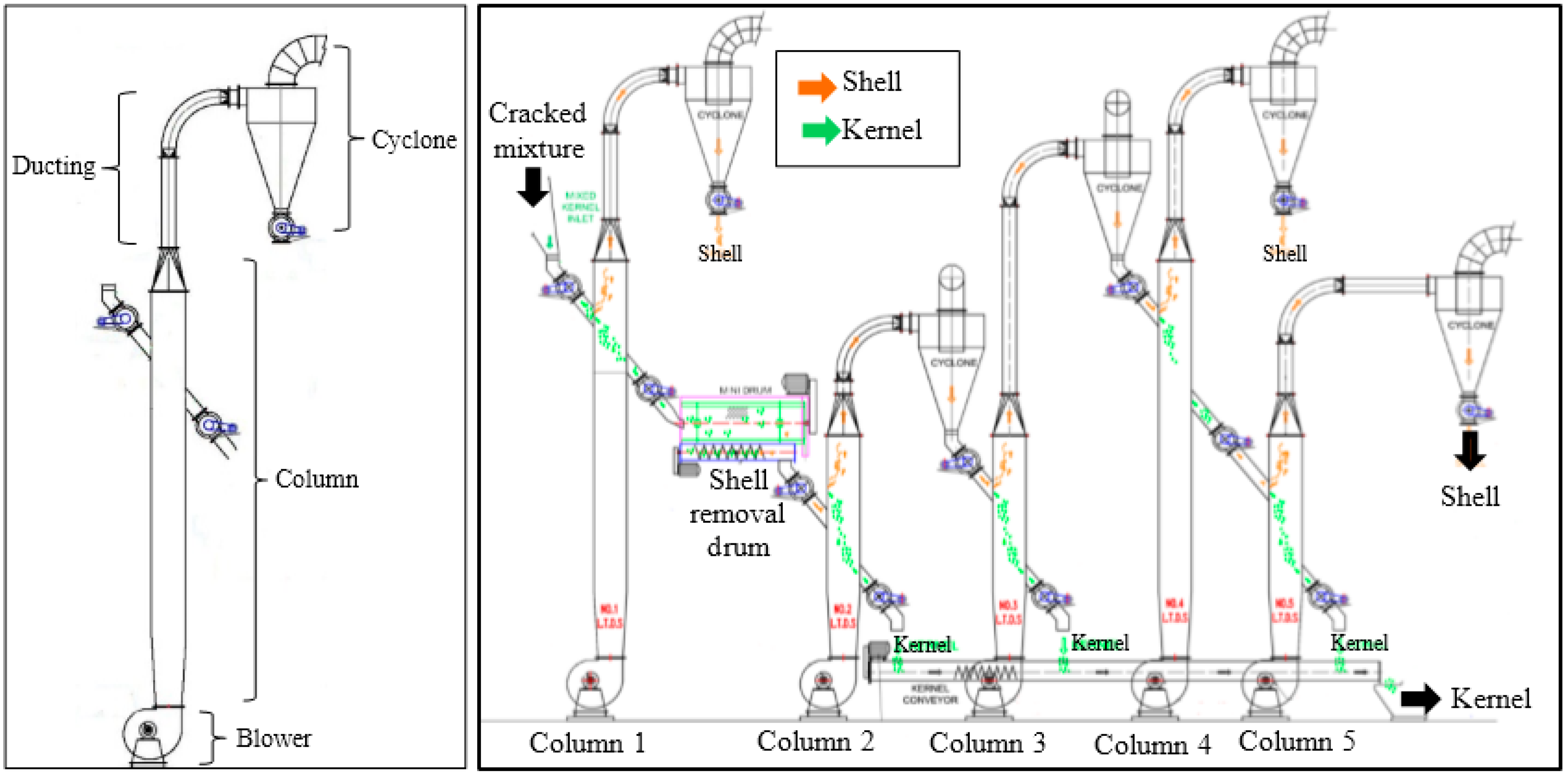
Table 1 shows the optimized setup for the five-stage winnowing column system for the dry kernel separation process in terms of airflow rate, damper opening and column height to achieve the desired 45 wt % of total kernel throughput. The cracked mixture fed into the system contained 
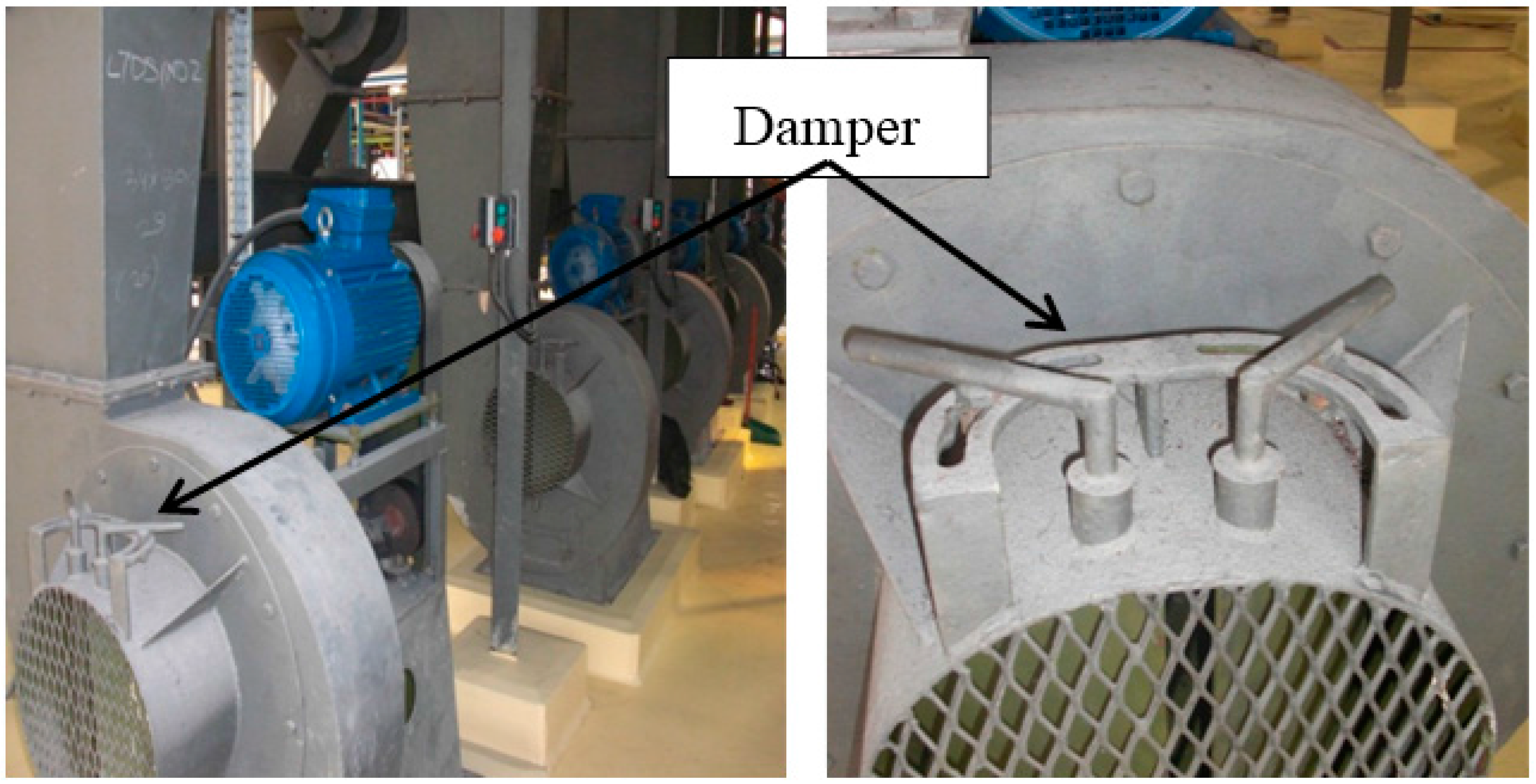
ca. 55 wt % shells and 45 wt % kernels; thus, the maximum recovery of kernel was at 45 wt % and maximum shell removal at 55 wt %. As mentioned previously, the system was designed so that shell and kernel would be discharged at Stages 1, 4, and 5 and Stages 2, 3, and 5, respectively. Separation of shell and kernel in a column is driven by the specific gravity differential of materials and in the presence of high velocity airflow blown by an electrical fan. Furthermore, different openings of the damper drive the variation in air velocity to suit the characteristic of the feed material.
We found most of the small shells (30–35 wt %) were successfully discharged at the first stage. Large and thin shells (10–12 wt %) were discharged at the fourth stage, whereas large and thick shells (5–8 wt %) were discharged at the fifth stage. Overall, the system showed excellent shell removal efficiency by more than 82 wt % (min. 45 wt % shell throughput), as shown in Table 1.
The highest removal of shells in the first stage was due to the highest airflow rate utilized at 257 m3/min in the first column compared to 202, 196, 173 and 173 m
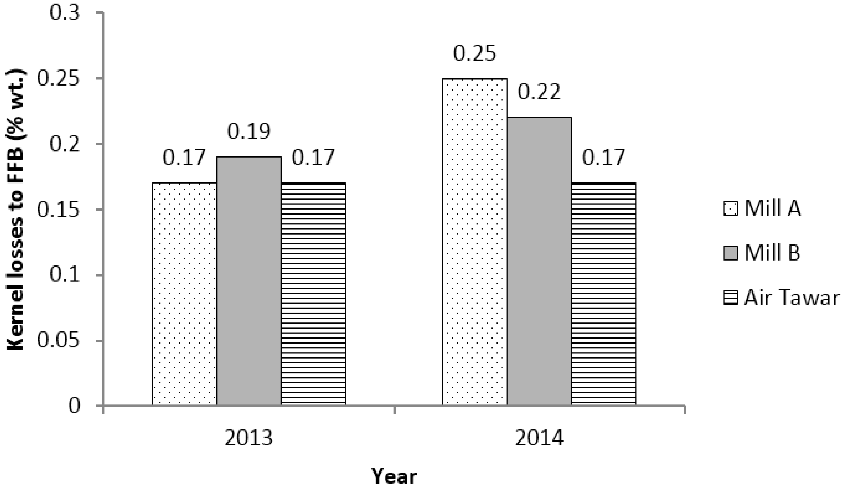
3/min in the second, third, fourth, and fifth columns, respectively. Technically, a high airflow rate blows the small light shells upwards and leaves the heavy kernels and thick shell fraction deposited at the bottom of the column. However, due to the high air velocity, this is also associated with a loss of light broken kernel that is blown away with the small shells, amounting to 0.1–0.2 wt % (kernel to FFB) (Table 2). For comparison, this loss is higher than the kernel losses at the fourth and the fifth stage, which are both in the range of 0.06–0.08 wt % (kernel to FFB) (Table 2). This stage makes use of a high column height (8.64 m) to allow longer separation time in order to effectively push up most of the small shells (Table 1). A similar case was also observed at the fourth stage where a high column design enables good removal of shells in the range of 10–12 wt % from the total throughput.
For the separation and recovery of the kernel, 20–28 wt % large whole kernels and large broken kernels were discharged at the second stage. The remaining 5–8 wt % and 5–7 wt % small whole kernels and small broken kernels were recovered at the third and fifth stages, respectively. In general, the system showed excellent kernel recovery efficiency by more than 67% (min. 30 wt % kernel throughput), as shown in Table 1.
The system was intentionally designed for the second stage to carry out most of the separation of large whole kernels. The discharge at the second-stage fraction was kept as clean as possible by using a high separating velocity in the separating column, represented by the highest airflow rate (202 m3/min) compared to the airflow rate at the third and fifth columns where kernel was also discharged (196 m3/min and 173 m3/min, respectively). This was achieved through the opening of the damper to 50% at the second stage, which provides a higher air velocity compared to opening the damper at the third and fifth columns to 40% and 30%, respectively. Nevertheless, we found that the recovered kernel from the second stage was contaminated with 1–2 wt % of free shells, which was still within the acceptable limit (Table 2). We note that the second and the third stages, which both accounted for almost 84% of the kernel recovery (max. 36 wt % of total throughput), had a lower column height at 5.03 m compared to 8.64 m for the first and fourth stages, which are meant for shell removal. In contrast to the shell removal principle, which requires a high column to allow a sufficient floating duration of shells, recovery of the kernel requires a short column to avoid kernel from being lifted to the upper end of the column.
The third stage, also designed for kernel recovery, used a lower separating velocity represented by a lower airflow rate (from 202 to 196 m3/min) by reducing the damper opening from 50% to 40% (Table 1). As the separation column throat area remained the same as for the first stage, the lower separating velocity was able to separate out the light kernel fraction in the form of small whole kernel and large broken kernel, both having almost the same specific gravity. About 5–8 wt % kernels (small whole and large broken kernels) were successfully discharged through the bottom outlet. Consequently, the remaining broken kernel and shell were lifted and deposited in the third-stage discharge cyclone for further separation. In addition to the optimum separating velocity, the height of the circular ducting from the column is much higher (Figure 1 (right)) to prevent kernel from being lifted to the cyclone. The height of the circular ducting was in the order of: third column > fourth column = first column > fifth column > second column (Figure 1 (right)). Results obtained confirm that kernel loss in the third-stage shell discharge outlet was in the range of 0.06–0.08 wt %, which was less than in the shell discharge outlet at the first stage (Table 2).
Small kernels and shells from the third-stage cyclone were then transferred by a screw conveyor to the feed inlet of the fourth-stage separating column where the large and thin shells (10–12 wt %) and smashed kernels (0.06–0.08 wt %) were lifted and delivered to the discharge cyclone for discharging into the boiler as fuel. The airflow rate here was further reduced from 196 to 173 m3/min by adjusting the setting of the damper position from 40% to 30%–35% opening. Apart from the designated air velocity, the reduced height of the cyclone from the column also cut-short the travelling distance of the lightweight shell along the ducting, therefore lifted almost all the shell and deposited it in the cyclone.
The fifth stage recovered the remaining 5–7 wt % small kernel and removed another 5–8 wt % large and thick shells. The fifth column also served a cleaning purpose, which helps the system to maximize kernel recovery, achieve a dry kernel separation process and generates zero effluent waste. The predecessor of this system that uses a four-stage separation technique still requires a wet separation process using claybath and hydrocyclone, indicating the remarkable concept and performance improvement of our design [14].
Another work reported by Olasumboye and Koya [17] demonstrated a separation technique using a rotary separator that employs a multi-cyclic-separation process for the dry mixture. The work reports the highest kernel recovery over feeding cracked mixture of 92%. The kernel purity was 73%, which indicates contamination of other foreign materials of up to 27% [17]. Our study, however, as presented in Table 2, showed better separation efficiency with maximum kernel losses over FFB processed of 0.36 wt %, equivalent to 97.5% of kernel recovery over feeding cracked mixture. In a later section, we discuss the KER over FFB processed instead of feeding cracked mixture. This is because the KER is a parameter commonly used among millers and therefore provides convenient data to actual end users. In addition to kernel recovery, purity of the recovered kernel in this study was much higher, ranging from 92 to 95 wt % (5–8 wt % shell contaminated in the kernel fraction), as shown in Table 2.

3.3. Kernel Recovery Rate

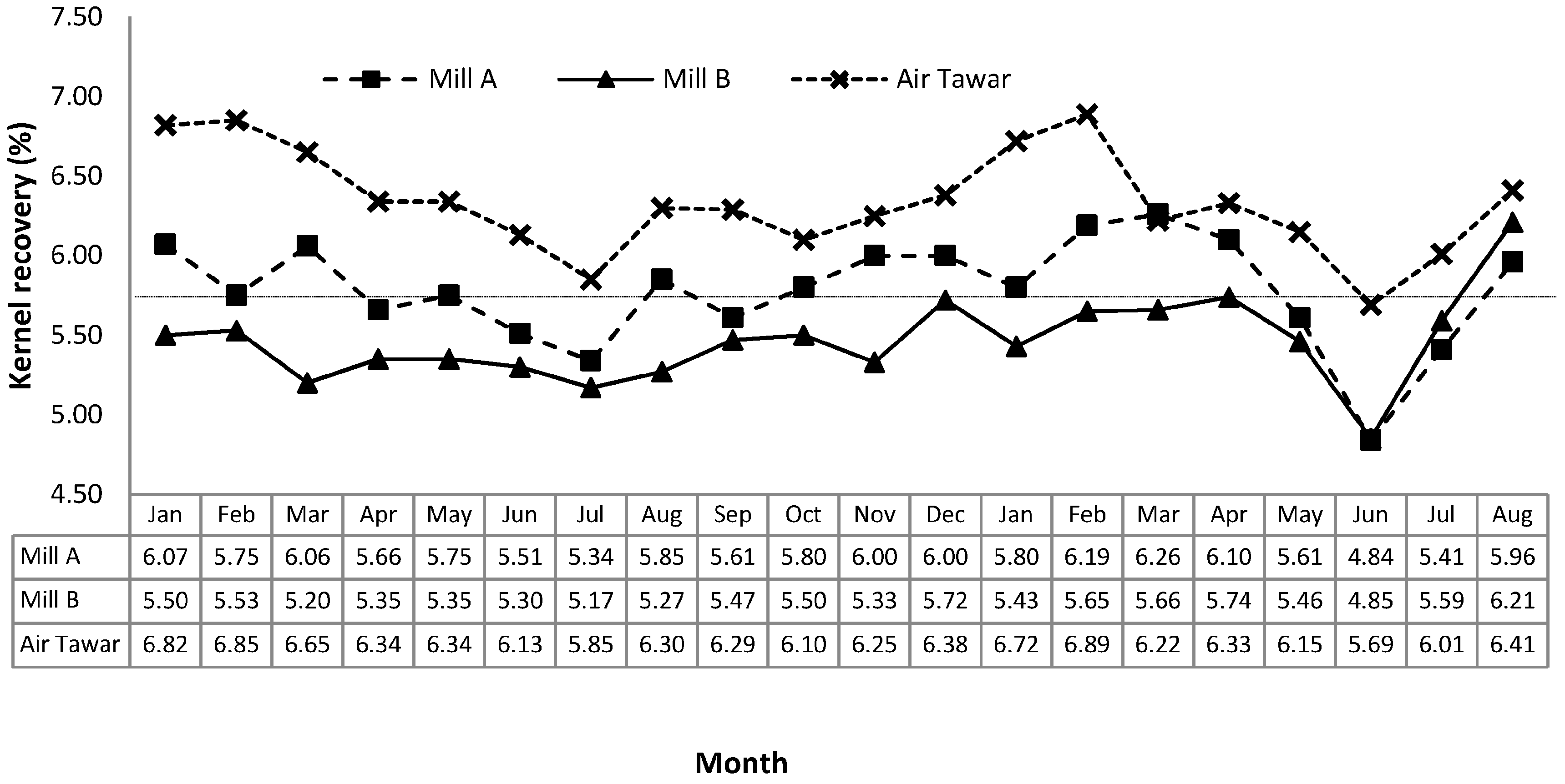
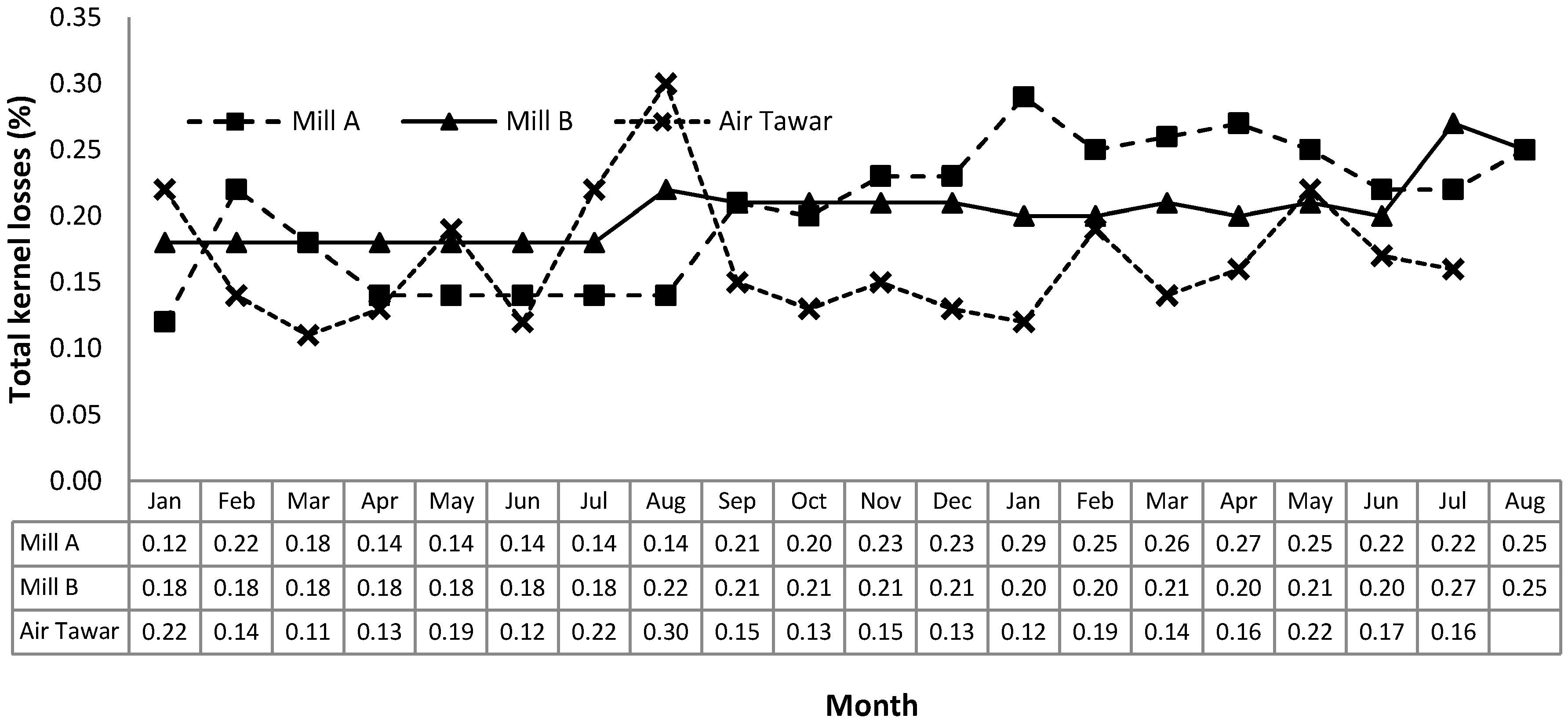
KER is commonly used to measure the kernel recovery performance of a POM calculated over the processed FFB. The palm oil milling sector makes use of this parameter to evaluate the production performance of POMs in addition to its main CPO production. In this study, the system performance in terms of KER and kernel losses between three commercial mills using different kernel separation system was evaluated on a monthly basis.
Figure 6 illustrates a comparison of the trend of KER in Air Tawar POM with other sister mills in the Johor region over a period of 20 months. Air Tawar POM, mill A and mill B show their KER values in the range of 5.69–6.89 wt %, 4.84–6.26 wt % and 4.85–6.21 wt %, respectively. In general, Air Tawar POM, which adopted a totally dry kernel separation process using the five-stage winnowing column system, showed a higher KER with an average KER of 6.34 ± 0.30 wt % compared to mill A and mill B, which had average KERs of 5.78 ± 0.34 wt % and 5.46 ± 0.28 wt %, respectively. Air Tawar POM maintained its KER values above 6.00 wt % at a 90% consistency rate, whereas the other two mills were only able to maintain their KER above the targeted limit of 6.00 wt % at a 35% and 5% consistency rate, respectively. In an attempt to reduce the effluent generated from the kernel separation system, mill A and mill B improved their system by using a combination of a two-stage winnowing column with a wet separation system using either hydrocyclone or claybath. However, as shown in Figure 6, their KER values were still below 6.00 wt % in most cases.
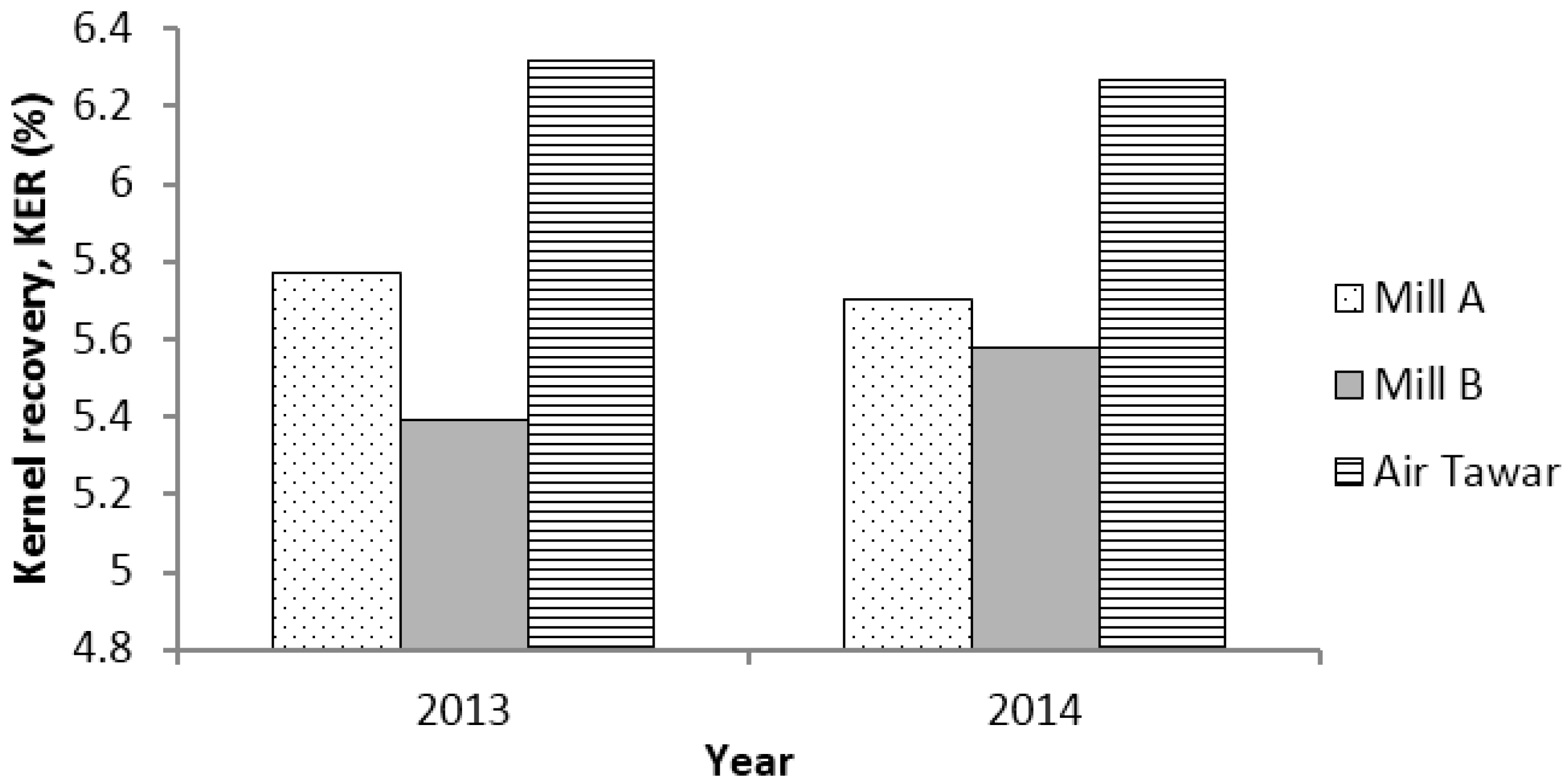
On a yearly basis for two consecutive years, Air Tawar POM recorded the highest average KER of 6.32 wt % and 6.27 wt % compared to mill A (5.77 wt % and 5.70 wt %) and mill B (5.39 wt % and 5.58 wt %) (Figure 7).
These results imply better KER associated with the five-stage winnowing column system for the kernel separation evaluated in this study. The conventional wet separation system, e.g., the claybath, comprises a cylindrical tank with an inverted cone shape to allow settlement of the heavy phase. A clay solution with a relative density of 1.12 is maintained in the claybath and slowly facilitates the sinking of denser shells and the floating of lighter kernels, both having a relative density in the range of 1.15 to 1.20 and about 1.07, respectively [16]. While the claybath separation is subjected to, and limited to, the density of the clay solution used, the five-stage winnowing column system optimizes the separation mechanism at each column based on the characteristics of the feed into the column, thereby reducing kernel losses and improving kernel recovery.

3.4. Kernel Losses

Similar to KER, measurement of kernel loss is also common in the POM sector so as to compare mill production performance. In general, the average total kernel loss in the shell bunker varied from 0.11 to 0.30 wt % to FFB with almost all the values found to be below 0.30 wt %. These values are far below the set limit of 0.30 wt % to FFB, and these losses do not contribute to the high dirt in the production of kernel.
Kernel losses at these three mills were maintained below 0.30 wt % (Figure 8). The kernel losses varied from 0.11 to 0.30 wt %, and Air Tawar POM was able to maintain the separation efficiency with minimal kernel losses below 0.20 wt % to FFB with an average of 0.17 ± 0.05 wt %. However, mill A and mill B experienced average kernel losses of 0.21 ± 0.05 wt % and 0.20 ± 0.02 wt % to FFB, respectively, both being below 0.20 wt % at a consistency rate of 35% (Figure 8).
On a yearly basis for two consecutive years, Air Tawar POM recorded low average kernel losses of 0.17 wt % compared to mill A (0.17 and 0.25 wt %) and mill B (0.19 and 0.22 wt %), respectively (Figure 9).

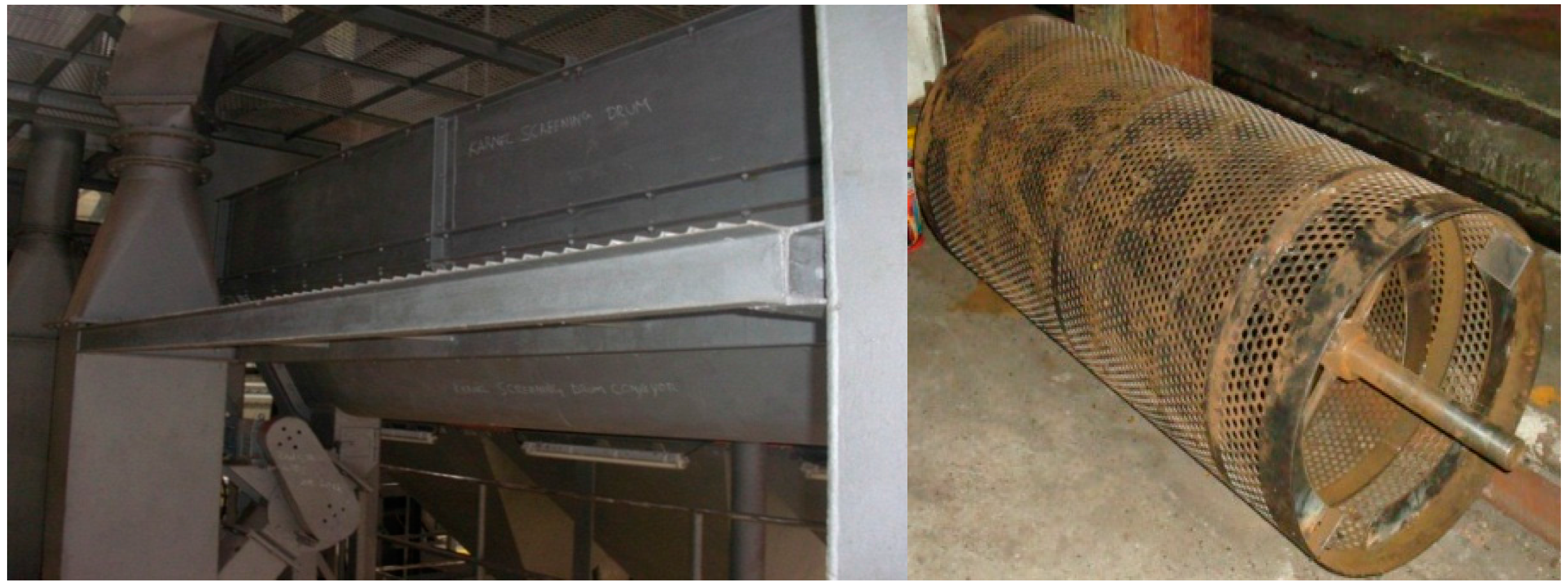
3.5. Maintenance Activity and Its Effect on Dirt Content

Maintenance activity is scheduled for every 2500 h and 5000 h of operation, equivalent to once for every 5–6-month interval. For every 2400 to 2600 h operation, the system required minor services and parts replacement, including the carbon steel liner plate for the cyclone and transfer trunking of the first and second columns. The replacement of the trunking column was due to the wearing from blown shells that hit the trunking.
There is a major service and parts replacement after 5000 h of operation, including replacement of the liner plate for the cyclone and trunking of all columns as well as servicing of the motor, bearing and impeller of the fan. The system eases the maintenance needs and requires less supervision in order to promote a user-friendly technology concept.
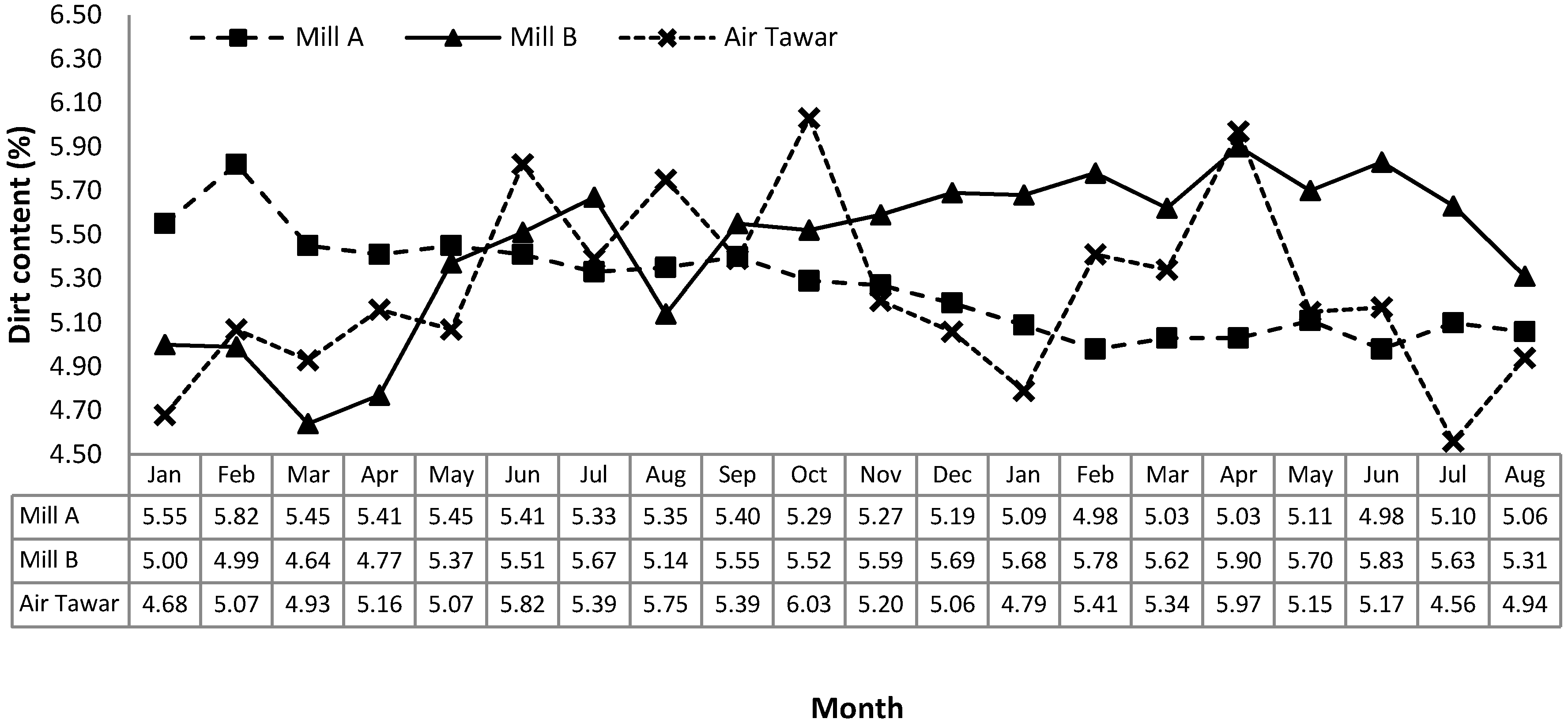
The wear and tear of the system’s parts influences its performance in terms of the dirt content in the recovered kernel. Figure 10 shows the trends of dirt content in the recovered kernel for the three mills over the 20 months of evaluation. For the Air Tawar POM, which utilized the five-stage dry kernel separation system, the total dirt and shell content in the kernel sampled at the end of the kernel conveyor varied from 4.56 to 6.03 wt %, and in most cases (80% consistency rate) the dirt content was below the set limit of 5.5 wt %. The high dirt content was observed for three different months as 5.82 wt %, 6.03 wt % and 5.97 wt %. In the first six months, during which the system starts its operation, the dirt content slowly increased from 4.68 wt % in the first month to 5.82 wt % in the sixth month. Maintenance was done gradually from Month 7 until Month 10, resulting in better (reduced) dirt content but still fluctuations. From Month 11 until Month 15, the system retained its dirt content below 5.5 wt % because of the new parts from maintenance. This trend was repeated for the next six-month cycle, thus justifying the need to undertake maintenance every 2500 h and 5000 h of operation.
Air Tawar POM experienced slightly lower average dirt content compared to other mills even with a totally dry separation system to separate kernel and shell. As shown in Figure 10, Air Tawar POM experienced an average dirt content of 5.24 ± 0.40 wt %, slightly lower than the dirt content experienced by Mill A and Mill B at 5.27 ± 0.22 wt % and 5.44 ± 0.36 wt %, respectively. Generally, thick shell could be separated efficiently by the wet separation system with either claybath or hydrocyclone, but the use of a shell removal drum in the five-stage winnowing column system eliminates the presence of thick shell and contaminant carryover as the dirt in the production kernel.
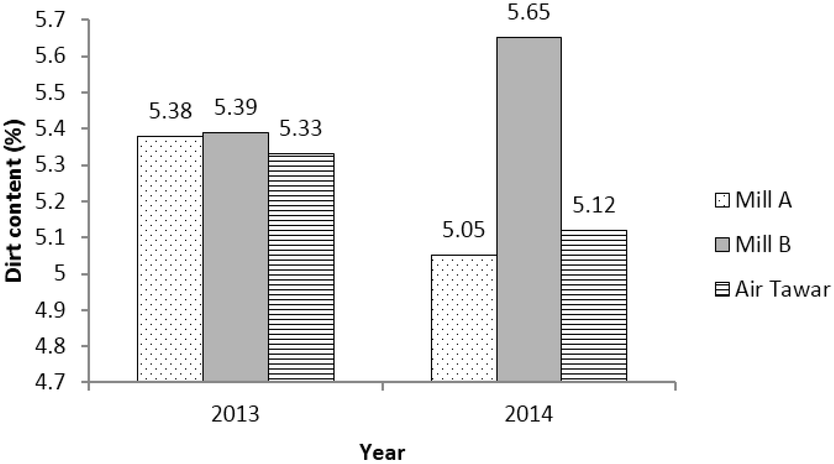
Over two successive years, the average dirt content in Air Tawar POM was 5.33 wt % and 5.12 wt %, whereas the dirt content in Mill A was 5.38 and 5.05 wt % and Mill B was 5.39 wt % and 5.65 wt % (Figure 11).

3.6. Power Consumption and Economic Analysis

The five-stage winnowing column system requires about 245 HP or 170 kW of power consumption, as tabulated in Table 3. The use of five columns to enhance the separation process and to maximize kernel recovery resulted in high power consumption, with nearly half the power (130 HP) for the operation of the columns, namely to blow air.
The cost of maintenance was calculated for an eight-month period over which the total FFB processed was 122,890 t in 2889 running hours. Two units of impeller for the first and third stages with a total cost of MYR9000 were replaced, and the cost of maintenance was less than MYR 0.10/t FFB processed. An additional cost incurred in the second year of operation is expected since more parts will be replaced after more operational hours. However, this cost will be very low compared to the conventional separation system. The only drawback of the five-stage winnowing column system is that it requires a higher capital cost of nearly MYR one million compare to the wet conventional system, which costs less than MYR500,000.
The kernel plant in Air Tawar POM has been in operation for nearly two years and has recorded an average of an additional min. of 0.3 wt % KER. With the actual FFB processed of 184,335 t/year, this will generate an additional production of palm kernel of 533 t/year. Calculated at the average price of palm kernel in 2015 at MYR1564 per tonne of palm kernel, an additional revenue of MYR844,560 per year could be generated [20]. Therefore, the expected payback period for the capital investment of MYR950,000 is less than two years.

4. Conclusions

A dry process to separate palm kernel and palm shell was developed using a series of five winnowing columns, each powered by a single blower unit. The blower was installed at the bottom of the column to create a forced-draught system with positive pressure along the column. Additionally, the blower system was incorporated with a damper flap to enable airflow rate adjustment to achieve good separation of kernel and shell. The separation in the column works on the principle of the different specific gravity of materials, where the air blown upwards causes the light material, usually palm shell, to rise. A partition was created inside the column to divert the airflow rate and consequently prevent a turbulent flow that would restrain the separation of materials. The five-stage winnowing column system was installed and evaluated at a local POM. Parameters evaluated included size distribution of feeding materials, airflow rate, column sizing, kernel recovery rate, dirt content and kernel losses. The system was able to recover up to 97.5% kernel from the mixture of palm kernel and shell, translated from maximum kernel losses of 0.36 wt %. The system produced kernel products of high purity, ca. 92–95 wt %, or 5–8 wt % shell contamination, in the recovered kernel. The KER throughout 20 months of continuous monitoring was in the range of 5.69–6.89 wt %, with most of the values achieving the minimum target limit of 6.00 wt %. Moreover, the system used no water in its separation process, therefore generated zero waste effluent. The novelty of the system could benefit millers in terms of profit, kernel quality, operational performance and maintenance as well as promote user-friendly operations by reducing the water and chemicals used by conventional wet separation.

Acknowledgments

We thank Felda Palm Industries Sdn Bhd (FPISB) and Air Tawar POM for their valuable support and cooperation in this project. We are grateful to all staffs of the milling group of MPOB who were involved in conducting this study.

Author Contributions

Rohaya Mohamed Halim designed and conceived the experiments, designed the system, analyzed the data and wrote the paper; Ridzuan Ramli designed the system; Che Rahmat Che Mat analyzed the data; Choo Yuen May reviewed the paper; Nasrin Abu Bakar designed, analyzed and documented the experimental results; and Nu’man Abdul Hadi analyzed the data and wrote the paper. All authors have read and approved the final manuscript.

Conflicts of Interest

The authors declare no conflict of interest.

Abbreviations

The following abbreviations are used in this manuscript:
POM
Palm oil mill
FFB
Fresh fruit bunch
CPO
Crude palm oil
KER
Kernel recovery rate
MYR
Malaysian ringgit

References

  1. Lin, S.W. Palm oil. In Vegetable Oils in Food Technology: Composition, Properties, and Uses, 2nd ed.; Gunstone, F.D., Ed.; Wiley-Blackwell: Oxford, UK, 2011; pp. 25–58. [Google Scholar]
  2. Norhaizan, M.E.; Hosseini, S.; Gangadaran, S.; Lee, S.T.; Ramezani, F.; Moghadasian, M.H. Palm oil: Features and applications. Lipid Technol. 2013, 25, 2011–2014. [Google Scholar] [CrossRef]
  3. Traitler, H.; Dieffenbacher, A. Palm oil and palm kernel oil in food products. J. Am. Oil Chem. Soc. 1985, 62, 417–421. [Google Scholar] [CrossRef]
  4. Sreedhara, N.; Arumughan, C.; Narayanan, C.S. Dehulling of palm kernel of oil palm (Elaeis guineensis) to obtain superior-grade palm kernel flour and oil. J. Am. Oil Chem. Soc. 1992, 69, 1015–1018. [Google Scholar] [CrossRef]
  5. Zainal, Z.; Yusoff, M.S.A. Enzymatic interesterification of palm stearin and palm kernel olein. J. Am. Oil Chem. Soc. 1999, 76, 1003–1008. [Google Scholar]
  6. Vaidya, R.; Chaudhary, G.; Raut, N.; Shinde, G.; Deshmukh, N. Synthesis of Biocomposites from Natural Oils—A Review. Available online: http://ipcbee.com/vol41/013-ICEBB2012-H00035.pdf (accessed on 15 April 2016).
  7. Haron, M.J.; Jahangirian, H.; Silong, S.; Yusof, N.A.; Kassim, A.; Rafiee-Moghaddam, R.; Mahdavi, B.; Peyda, M.; Abdollahi, Y.; Amin, J. Benzyl and methyl fatty hydroxamic acids based on palm kernel oil as chelating agent for liquid-liquid iron(III) extraction. Int. J. Mol. Sci. 2012, 13, 2148–2159. [Google Scholar] [CrossRef] [PubMed]
  8. Palm Oil Research Institute of Malaysia. Part 1. General description of the palm oil milling process. In Palm Oil Factory Process Handbook; Palm Oil Research Institute of Malaysia: Kuala Lumpur, Malaysia, 1985. [Google Scholar]
  9. Vijaya, S.; Choo, Y.M.; Halimah, M.; Zulkifli, H.; Tan, Y.A.; Puah, C.W. Life cycle assessment of the production of crude palm oil (Part 3). J. Oil Palm Res. 2010, 22, 895–903. [Google Scholar]
  10. Nizamuddin, S.; Jayakumar, N.S.; Sahu, J.N.; Ganesan, P.; Bhutto, A.W.; Mubarak, N.M. Hydrothermal carbonization of oil palm shell. Korean J. Chem. Eng. 2015, 32, 1789–1797. [Google Scholar] [CrossRef]
  11. Rahman, M.M.; Adil, M.; Yusof, A.M.; Kamaruzzaman, Y.B.; Ansary, R.H. Removal of heavy metal ions with acid activated carbons derived from oil palm and coconut shells. Materials 2014, 7, 3634–3650. [Google Scholar] [CrossRef]
  12. Ismaiel, A.A.; Aroua, M.K.; Yusoff, R. Cadmium (II)-selective electrode based on palm shell activated carbon modified with task-specific ionic liquid: Kinetics and analytical applications. Int. J. Environ. Sci. Technol. 2014, 11, 1115–1126. [Google Scholar] [CrossRef]
  13. Rohaya, M.H.; Nasrin, A.B.; Choo, Y.M.; Ma, A.N.; Ravi, N. A commercial scale implementation of Rolek™ palm nut cracker: Techno-economic viability study for production of shell-free kernel. J. Oil Palm Res. 2006, 18, 153–167. [Google Scholar]
  14. Rohaya, M.H.; Nasrin, A.B.; Mohd Basri, W.; Choo, Y.M.; Ridzuan, R.; Ma, A.N.; Ravi, N. Maximizing the recovery of dry kernel & shell via a 4-stage winnowing column. In Proceedings of the Malaysian Palm Oil Board (MPOB) International Palm Oil Congress, Kuala Lumpur, Malaysia, 9–12 November 2009.
  15. Andoh, P.Y.; Agyare, W.A.; Dadzie, J. Selection of an ideal mesh size for the cracking unit of a palm kernel processing plant. J. Sci. Technol. 2010, 30, 109–118. [Google Scholar] [CrossRef]
  16. Okoronkwo, C.A.; Ngozi-Olehi, L.C.; Nwufo, O.C. The adaptation of clay-bath and hydro-cyclones in palm nut cracked-mixture separation to small—Scale oil palm processing industry. Int. J. Mod. Eng. Res. 2013, 3, 2023–2026. [Google Scholar]
  17. Olasumboye, A.; Koya, O. A rotary separator for the dry mixture of palm kernel and shell. Innov. Syst. Des. Eng. 2014, 5, 32–42. [Google Scholar]
  18. Rohaya, M.H.; Osman, A. The quality of Malaysian palm kernel: Effect of shell and broken kernel on the quality of final products. In Proceeddings of the National Seminar on Palm Oil Milling, Refining Technology, Quality and Environment (Malaysian Palm Oil Board), Sabah, Malaysia, 27–28 November 2002.
  19. Shafii, A.F. Nut cracking using ripple mill. PORIM Bull. 1989, 19, 8–18. [Google Scholar]
  20. Price of Palm Products. Available online: http://bepi.mpob.gov.my/index.php/statistics/price/monthly.html (accessed on 1 April 2016).
Figure 1. (left) A single stage consists of a blower, a column, a ducting and a cyclone unit; and (right) a five-stage winnowing column system for the separation of the kernel from the cracked nut mixture.
Technologies 04 00013 g001
Figure 2. Blower damper installed at the bottom of the column.
Technologies 04 00013 g002
Figure 3. Shell removal drum placed between the first and the second stage.
Technologies 04 00013 g003
Figure 4. (left) Perforated plate to measure different nut and kernel size; and (right) horizontal cross-sectional diameter of nut and kernel.
Technologies 04 00013 g004
Figure 5. Nut and kernel size distribution of the feeding materials.
Technologies 04 00013 g005
Figure 6. Monthly KER for the three evaluated mills.
Technologies 04 00013 g006
Figure 7. Yearly average kernel recovery rate for the three evaluated mills.
Technologies 04 00013 g007
Figure 8. Monthly kernel losses to FFB for the three evaluated mills.
Technologies 04 00013 g008
Figure 9. Yearly average kernel losses to FFB for the three evaluated mills.
Technologies 04 00013 g009
Figure 10. Monthly dirt content in the shell bunker for the three evaluated mills.
Technologies 04 00013 g010
Figure 11. Yearly average dirt content for the three evaluated mills.
Technologies 04 00013 g011
Table 1. Optimized setup for the five-stage winnowing column system for the dry separation of kernel and its product throughput.
StageBlower Power (HP)Airflow Rate (m3/min)Damper Open-up (%)Column Height (m)Products DischargedProducts DescriptionProducts Throughput (wt %)
Min.Max.
130257508.64ShellSmall shell3035
225202505.03KernelBig whole kernel2028
Big broken kernel
325196405.03KernelSmall whole kernel58
Small broken kernel
42517330–358.64ShellBig and thin shell1012
52517330–355.03ShellBig and thick shell58
KernelSmall kernel57
Total shell throughput (wt %)4555
Total kernel throughput (wt %)3043
Table 2. Contaminants in terms of 1 kernel losses and 2 free shells in the recovered products.
StageProducts DischargedContaminantsThroughput (wt %)
Min.Max.
1ShellKernel losses0.10.2
2KernelFree shells1.02.0
3KernelFree shells2.03.0
4ShellKernel losses0.060.08
5ShellKernel losses0.060.08
5KernelFree shells2.03.0
Total kernel losses (wt %)0.220.36
Total free shells (wt %)5.08.0
1 Kernel losses are reported based on FFB processed. 2 Free shells are reported based on (kernel) sample collected.
Table 3. Power consumption for the five-stage winnowing column system.
MachineQuantityPower
(HP)(kW)
Cracked mixture conveyor (top and bottom)2118
Cracked mixture elevator17.55.5
Winnowing column5130100
Air lock175137.4
Blower24030
Kernel conveyor15.54
Total-245170

