2. Experimental Section
A wireless accelerometer, conveniently housed in a waterproof watch casing which could be worn by an interventional surgeon below surgical gloves and operating at 868 MHz (EZ-Chronos, Texas Instruments, Austin, TX, USA) (
Figure 1), was interfaced to the lesion localization and probe targeting software of the specialized MRI systems written in LabView (National Instruments, Austin, TX, USA). The acceleration outputs of the device were allocated to two plane rotation angles and to the slice offset or field of view (FOV) offset as chosen by the operator. Zero position was set with the watch located horizontally and pointing into the magnet. Rotation of the accelerometer by ±90 degrees around two axes was then calibrated and used to adjust the selected scan plane angle and slice offset interactively. The accelerometer was zeroed in the horizontal plane and calibrated so that a 90 degree rotation in physical space achieved by moving the forearm corresponded to a ±90 degree plane rotation or a ±FOV/2 slice offset depending on the direction of rotation. Worn by the operator, the accelerometer device would allow the surgeon to use his wrist to interact directly with the software to plan the next scan plane. The device is not specifically designed to track the location of an instrument or biopsy device but to give the surgeon a non-contact method of interacting with planning software.
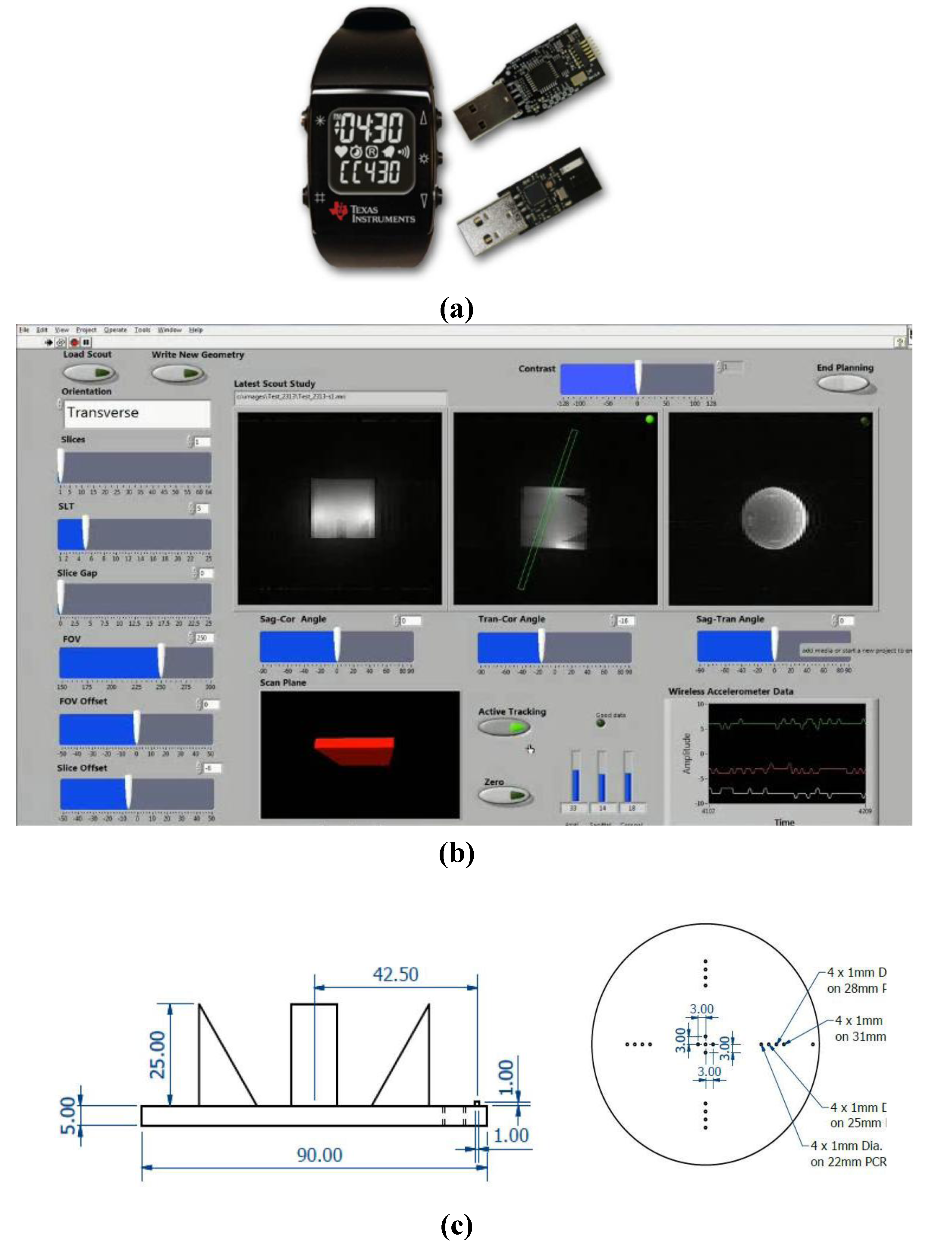
Figure 1.
(a) The wireless accelerometer (EZ Chronos model 430, Texas Instruments, Austin, Tx, USA) is housed in a sports watch and transmits data from the accelerometer over a 868 MHz radio link to a USB wireless transceiver. Labview software is used to receive the wireless data and interface it to the lesion localization and probe targeting software of specialized interventional MRI systems with a 50 ms update time. (b) The customized Labview graphical user interface (GUI). (c) The precise geometry of the inserts in the quality assurance (QA) phantom used to assess the angular (±3°) and translational (±1 mm) accuracy of the geometrical planning through the wireless interface. The phantom was 90 mm internal length. Angles and offsets of acquired slices were calculated using the visible spatial features and dimensions of the QA phantom in each planned slice using standard geometrical methods and ImageJ analysis software (NIH, Bethesda, MD, USA).
Testing was performed on a dedicated 0.17T MR orthopaedic and neonatal scanner (InnerVision MRI Ltd., Bradley, UK) (
Figure 2a) and also an Intra-Operative MR Scanner (Specialty Magnetics Limited, Middlesex, UK) (
Figure 3) currently operated at 0.5T for occupational health reasons and optimised for minimally invasive breast procedures. Both systems used LabView based research spectrometers with custom-designed interactive GUIs (ISD Ltd., Bradley, UK). A USB PC interface to the wireless accelerometer, including a low power RF transceiver (TI CC1111, Texas Instruments, Austin, TX, USA), was housed in the scan computer located outside the screened room of each system to receive the wireless data stream.
Angular accuracy and slice offset were assessed at 0.17T using a customized quality assurance (QA) phantom (90 mm height × 90 mm OD) (
Figure 1c). Wireless planned oblique images of the QA phantom with defined geometry and the elbow region of a volunteer were acquired at 0.5T and 0.17T respectively, with a T1-weighted spin echo sequence (TR/TE = 300/20 ms) with 1 mm in-plane resolution, SLT = 5 mm, NEX = 2 (
Figure 1b and
Figure 2b, respectively) to assess the oblique planning capability. Through the precisely known geometry of the phantom (
Figure 1c), including the slice thickness evaluation ramps and spatial resolution bars, angles could be determined by visualising specific landmarks in the acquired MR images. Images of the QA phantom were also acquired using the T1-weighted spin echo sequence with and without the device present and active within the magnet room to assess for radiofrequency line artifacts or degradation of signal to noise ratio by the wireless device.
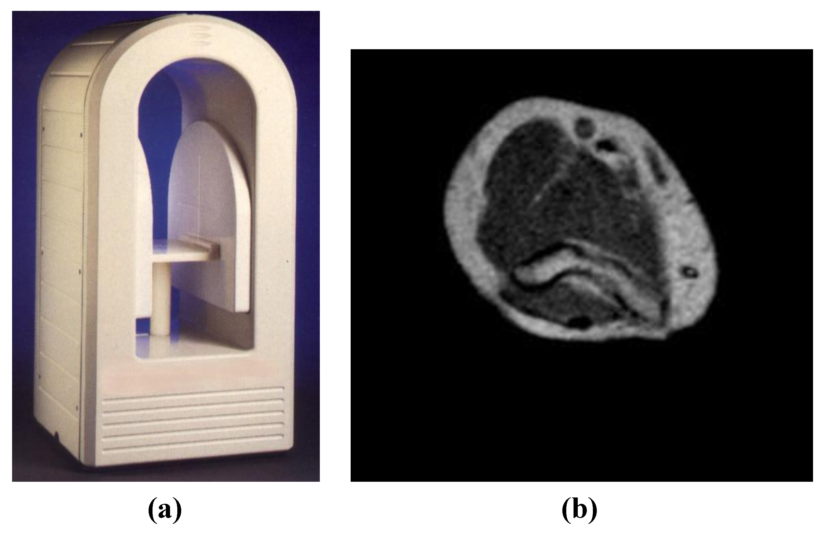
Figure 2.
(a) A specialised, open low field (0.17T) MRI system used for orthopaedic and neonatal applications providing easy access for interventional procedures (InnerVision MRI Ltd., Bradley, UK). The footprint of the magnet is 500 × 500 mm and the iso-centre of the magnet is only 250 mm from the front face of the magnet covers. (b) Wireless planned oblique image of the elbow region of a volunteer acquired at 0.17T with a T1-weighted sequence (TR/TE = 300/20 ms) with 1 mm in-plane resolution, SLT = 5 mm, NEX = 2. This image was acquired with the wireless device active at the edge of the uniform magnet volume within the screened room and showed no degradation of signal to noise ratio or line artifacts.
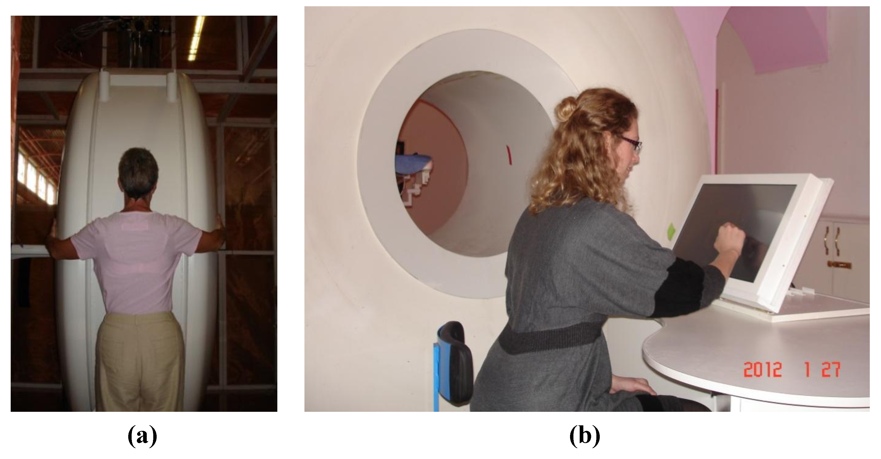
Figure 3.
(a) A superconducting magnet based Intra-Operative Breast MR Scanner (Specialty Magnetics Limited, Middlesex, UK) currently operated at 0.5T for occupational health reasons with 70 cm bore-length and 70 cm bore-diameter. (b) MR Scanner features an MR-compatible, in-room, touchscreen Operator’s Terminal through which the Clinician(s) can control all the subsystems of the MR Scanner and perform interventional procedures under real-time MRI guidance. MR Scanner also features a highly maneuverable Patient Positioning System which, as well as traditional vertical and horizontal travel, can also rotate clockwise or counter clockwise to locate the breast precisely at iso-centre of the magnet.
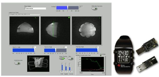
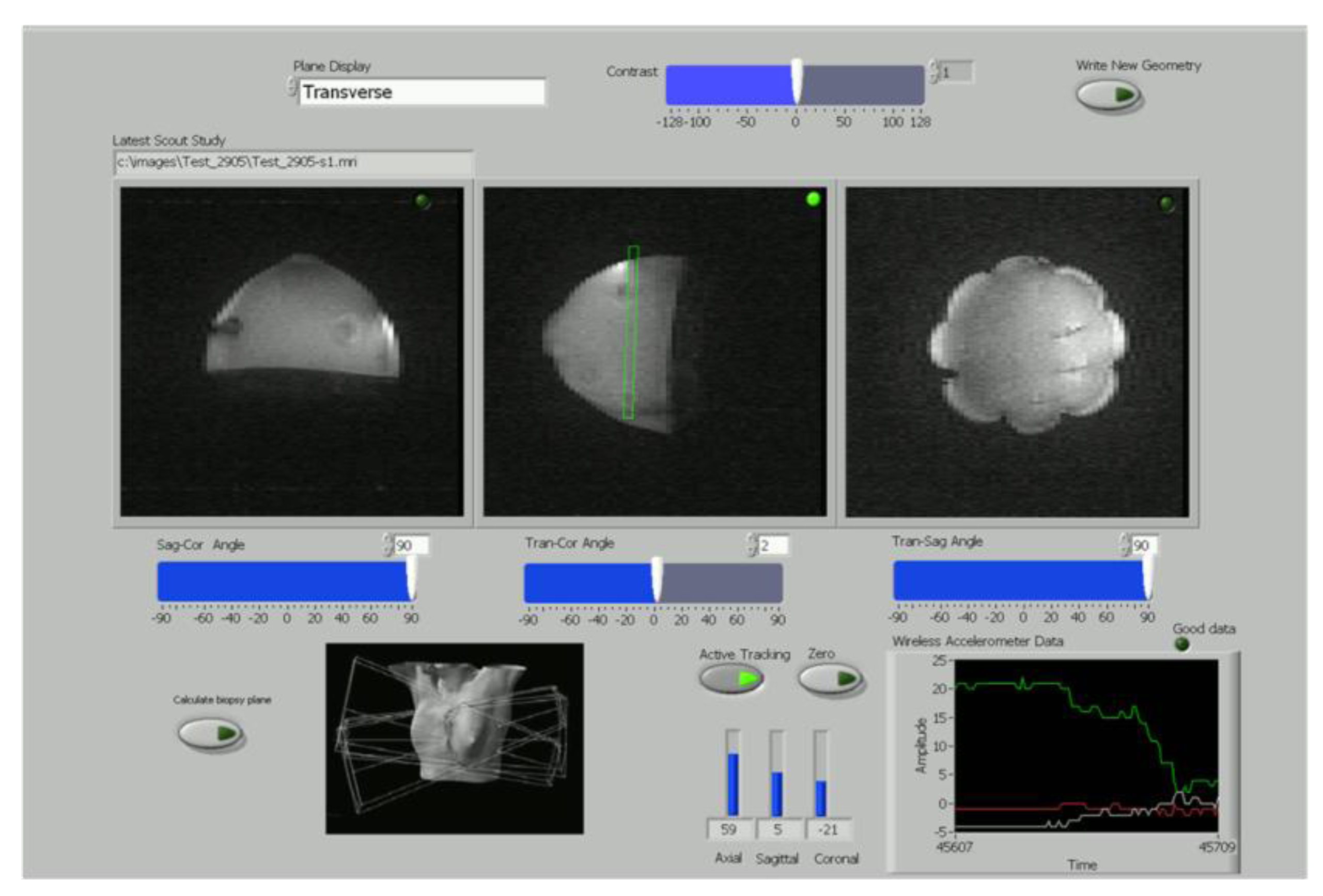
Figure 4.
A simplified version of the LabView wireless interactive geometry planning software showing three scout images acquired at 0.5T from the breast phantom in axial, sagittal and coronal planes with the planned slice superimposed in green for the operator.
Figure 4.
A simplified version of the LabView wireless interactive geometry planning software showing three scout images acquired at 0.5T from the breast phantom in axial, sagittal and coronal planes with the planned slice superimposed in green for the operator.
The suitability of the wireless device for MR scan plane adjustment in real time during biopsy was tested using the Intra-Operative Breast MR Scanner (Specialty Magnetics Limited, Middlesex, UK). A touchscreen-compatible GUI for the LabView (National Instruments, Austin, TX, USA) spectrometer was constructed (
Figure 4). This allowed both the wireless device and MR sequences to be initiated from the face of the MR scanner.
A gelatin-based breast biopsy phantom was employed, containing several spherical inclusions (8–12 mm ID) at varying depths and heights to mimic cysts (pure distilled water), fat (corn oil) and contrast-enhanced tumours (short T1 Gadolinium solutions). These inclusions were used to evaluate lesion targeting with the biopsy probe. A commercially available vacuum-assisted breast biopsy (VABB) system (MR Mammotome System, Devicor Medical Products, Cincinnati, OH, USA) was used to test the biopsy procedure with an 8G MR-compatible biopsy targeting set (Mammotome MR Targeting Set, 115 mm length). To avoid susceptibility artifacts during the evaluation, the ceramic obdurator within the biopsy set was used to target inclusions within the breast phantom. The biopsy probe was thus visible within the MR images as a signal void.
A freehand biopsy procedure was performed in two parts: (i) calculation of an initial visualization scan plane containing both needle entry point and lesion; (ii) interactive lesion targeting using the wireless device.
(i) A fiducial marker (short T1 Gadolinium solution) was placed against the phantom in order to locate a nominal needle entry point. A set of low-resolution coronal images (FLASH sequence: TR/TE = 60/5 ms, matrix = 128 × 256, SLT = 3 mm, NEX = 2) were then acquired to include both the fiducial and the target inclusion. Using the customized GUI, the operator located both objects within the coronal slices and used the software to automatically calculate an initial axial-coronal scan plane containing both objects. This provided an initial visualization scan plane for a free-hand biopsy. By superimposing this initial scan plane on three scout images (axial, sagittal and coronal), the operator could easily visualize the orientation of this plane within the phantom (see planned slice in
Figure 4).
(ii) Dynamic images were acquired using a FLASH sequence (TR/TE = 60/5 ms, matrix = 64 × 256, SLT = 3 mm, NEX = 1) with a temporal resolution, including 8 channel 2DFT reconstruction and image display, of 4 s allowing the biopsy needle to be tracked using a series of 7–8 images during a needle insertion. Starting from the initial visualization scan plane planned in (i), the operator was able to use the wrist-mounted wireless device to interactively adjust this initial imaging scan plane as the probe moved towards the lesion. The linked touchscreen GUI displayed the scan planes selected by the wireless accelerometer during the biopsy procedure together with the targeting images corresponding to the selected plane (
Figure 5). The time taken to move the probe to the planned target was typically 30 s.
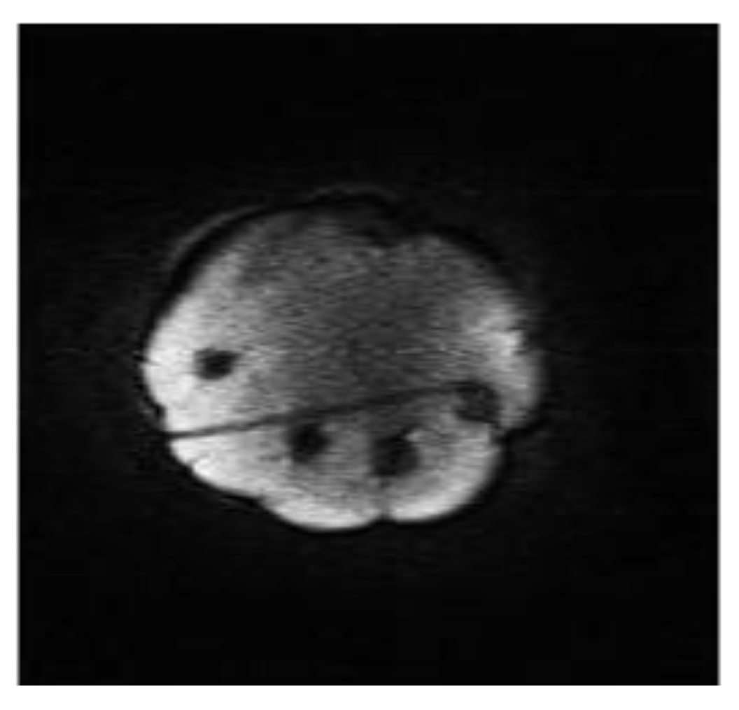
Figure 5.
The track of a biopsy needle acquired at 0.5T which has been planned using the wireless planning software.
Figure 5.
The track of a biopsy needle acquired at 0.5T which has been planned using the wireless planning software.
3. Results and Discussion
The wireless interface operated effectively with both of the interventional MR scanners (
Figure 2a and
Figure 3) during image acquisition. The wireless device was not affected by the magnetic or radiofrequency fields during imaging (the device was kept outside the transmit coils) and did not produce interference on the images. This was to be expected given the widely different operating frequencies between the device (868 MHz) and the MRI Larmor frequencies (21.3 MHz and 7.2 MHz at 0.5T and 0.17T, respectively). The USB interface was extended partially into the RF screened room waveguides of each system to provide improved reception with the RF screened room door fully closed.
Figure 1b shows a planned slice on the customized QA phantom (green rectangle on central image). Two of the orthogonal accelerometer outputs (shown bottom right) are assigned to slice offset and plane rotation angle respectively. Angular accuracy of ±3 degrees and a slice offset of ±1 mm were found at 0.17T using the customized QA phantom. Images of the QA phantom and a volunteer’s elbow were acquired at 0.5T and 0.17T respectively, dependent on the wireless accelerometer output. Typical examples are shown in
Figure 1b and
Figure 2b, respectively.
The wireless device could be used to interactively adjust the scan plane going through both the target-lesion and the biopsy-probe in real time (50 ms update time) based on operator wrist rotation with no other physical contact to the system. During minimally-invasive procedures, this would ensure sterile operation. An easy-to-use graphic user interface (GUI) is essential for greater clinical adoption of interventional MR procedures.
Figure 4 displays the simplified version of the LabView wireless interactive geometry planning software which was designed specifically as a touchscreen-compatible GUI for this study. Together with the wireless accelerometer output, large slide-bars were incorporated to give the operator easy control of the imaging sequences. The use of a plastic stylus on the touchscreen GUI gave the user straight-forward simultaneous control of the wireless device and MR imaging whilst maintaining a sterile environment. Although a number of MR systems have included novel GUIs, the majority of these systems still locate the software navigation within the external MRI control room [
6,
8]. Although projection techniques have been used to good effect, this still isolates the operator from essential real-time control of the procedure [
9,
10]. The touchscreen Operator’s Terminal control afforded by the Intra-Operative MR Scanner (Specialty Magnetics Limited, Middlesex, UK) design was highly conducive to effective clinical use of the wireless accelerometer since it allowed tableside sequence triggering and procedure monitoring (
Figure 3b). A dynamic imaging sequence enabled the operator to easily target an inclusion using wrist motion to interactively select the image scan plane in real time.
Figure 5 displays a typical image acquired mid-way through a biopsy procedure using the breast phantom with both the biopsy probe and target inclusions visible as signal drop out.
Instrument tracking in MRI can be broadly divided into two categories: passive and active. Within the first category, visualization of the probe is deduced from the susceptibility artifact induced by the instrument itself, and guidance is achieved by navigation in relation to passive fiducial markers. Without automatic slice selection of scan planes, passive techniques require manual slice calculation and repositioning which add time to interventional procedures. However, this simpler approach has been widely adopted in clinical settings, in particular for MRI-guided breast biopsy [
1,
11,
12,
13]. In contrast, active tracking gives the operator direct instrument control with immediate feedback under real-time MR image guidance. A number of active tracking techniques have been developed, including optical tracking with an infra-red camera and mirrors [
14,
15] and also the use of MR micro-receiver coils within the device to induce local inhomogeneities within the magnetic field [
16,
17,
18]. Although optical tracking provides a wireless approach, it requires line-of-sight access for accurate guidance which can be problematic in many MR scanner designs. Localization via micro-receiver coils can also provide a wireless solution if the coils are well tuned, matched and de-coupled to one another but this can be technically challenging and very costly. Consequently, it is more common for micro-coil tracking to be used with a conductive wire which introduces safety issues such as radiofrequency heating [
5]. In addition, inhomogeneities within the B
0 field can affect micro-coil localization. In contrast, the wireless accelerometer trialled within this study was able to provide an effective low-cost, wireless solution that did not interfere with MR imaging and conferred the added advantage of sterile operation.
This study was subject to a number of limitations. The wireless accelerometer has been shown to provide real-time plane rotation and slice offset information to the operator. However, at the time of this study, the MR sequences available to us were too slow to provide real-time image iteration during the phantom biopsy procedure. However, the use of FLASH was able to demonstrate proof of principle and subsequent work will test the accelerometer with more rapid sequences. In addition, although the wireless accelerometer device within this study was evaluated on interventional MR systems operated at relatively low magnetic field systems, translation of the device to much higher-field MR systems would also be feasible.
This study presents the first attempt to use a wireless accelerometer for active instrument tracking within the MR environment. It establishes that a watch-mounted accelerometer can provide sterile, cost-effective and straight-forward user control for interventional procedures under MR guidance.

