1. Introduction
The aerodynamic benefit provided by high-aspect-ratio wings makes them an attractive option for the aircraft designer. The slender planform of such wings reduces the unwanted effects of tip vortices and thus, when compared to lower aspect ratio designs, a greater lift-to-drag ratio may be achieved at certain flight conditions. Traditionally, high-aspect-ratio wings have featured predominantly in high altitude, long endurance (HALE) aircraft, seeing use in unmanned applications such as military reconnaissance and communication services relay. Recently, however, there has been an increase in the commercial interest in high-aspect-ratio wings and their applicability to the civil aviation industry [
1]. Manufacturers are seeking more economically and environmentally viable aircraft and thus solutions located outside of typical design envelopes are being investigated. Span extension technologies are among a variety of novel wing concepts currently being researched in the pursuit of greener aircraft.
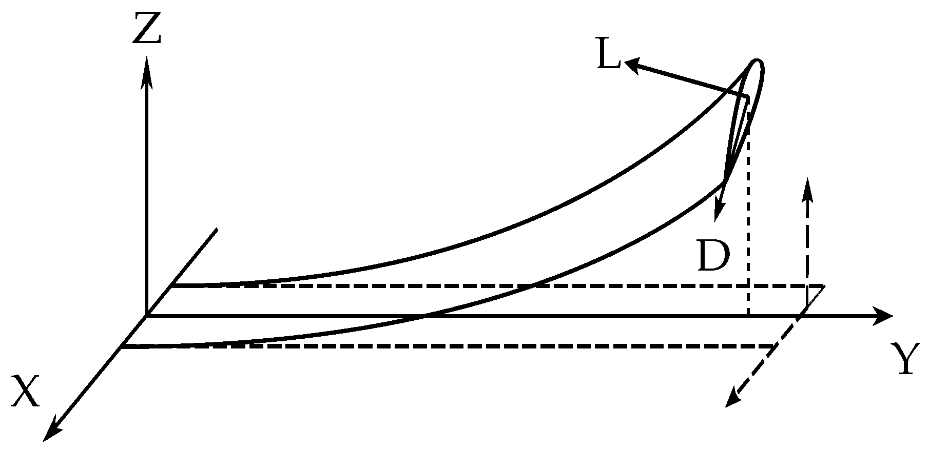
An inherent and undesirable characteristic of high-aspect-ratio wings is their flexibility. Relative to conventional designs, greater span-to-chord ratios lead to greater bending moments and larger wing deformations under aerodynamic loading. These large deformations are problematic from an aeroelastics perspective, as classical toolsets for static and dynamic analysis rely on
linear theory and thus assume wing deflections to be small. When wing deflections are not small, the aeroelastic system becomes geometrically
nonlinear and aerodynamic forces are non-negligibly re-orientated relative to the aircraft (acting as a ‘follower force’, where lift and drag components are no longer assumed to act solely in the vertical and horizontal planes, see
Figure 1). Increased torsional flexibility may also result in outboard wing sections achieving angles of attack large enough for aerodynamic nonlinearity (i.e., stall resulting from flow separation) to be significant. The presence of these nonlinearities means that the aeroelastic response of high-aspect-ratio wings cannot be adequately predicted by linear methods and therefore the use of nonlinear techniques is necessary.
As a general field, nonlinear aeroelasticity has been a very active area of research for a number of decades [
2]. There exists a vast, diverse body of literature that investigates how various physical sources of nonlinearity, such as cubic stiffness in aerofoils or ‘freeplay’ in control surfaces, relate to static and dynamic aeroelastic phenomena (e.g., Ref. [
3]). Limit cycle oscillations (LCOs) are an important type of nonlinear response and are a common theme throughout many of these studies; these periodic solutions have finite amplitude and often bound the oscillatory growth resulting from linear instability. LCOs are closely associated with flutter in nonlinear aeroelastic systems and are typically identified using numerical integration methods.
Studies specifically pertaining to high-aspect-ratio wings have so far demonstrated the existence of complex dynamical behaviour. Large, static wing deformation has been shown to affect flutter; the significant shift in structural frequencies means that destabilising modal interactions can occur at airspeeds different to those predicted using strictly linear modelling. Indeed, when compared to nonlinear analysis (involving
linearisation about nonlinear equilibria), linear assumptions have been shown to significantly overestimate flutter boundaries [
4]. Moreover, the flight dynamics and gust responses of flexible aircraft have been shown to vary significantly when large flexibility is accounted for [
5].
Critically, both numerical and experimental studies have found evidence of LCOs existing at airspeeds below nonlinear flutter boundaries [
6,
7,
8]. While LCOs occurring beyond the flutter boundary (i.e., supercritical LCOs) are desirable, as they limit what would otherwise be a divergent oscillation, the presence of subcritical LCOs is highly undesirable. Unless identified and accounted for using nonlinear analysis, these phenomena may occur within the operational envelope of an aircraft and could therefore have serious safety consequences. The industry drive towards more flexible, high-aspect-ratio wings means that subcritical LCOs must be better understood and, if possible, to be accounted for during conceptual design using nonlinear methods.
The present study demonstrates how very complex LCO behaviour in a high-aspect-ratio wing can exist due to geometric nonlinearity alone, without the inclusion of nonlinear or unsteady aerodynamic effects. Furthermore, it shows how numerical continuation techniques can be used to readily obtain such solutions, over broad regions of parameter space, without the need for exhaustive numerical integration. In
Section 2, the underlying nonlinear theory behind LCO behaviour is briefly discussed, together with an overview of numerical continuation.
Section 3 then provides an outline of the aeroelastic formulation and the nominal wing parameters, which are derived from Ref. [
6]. The static properties of the wing are obtained via the computation of natural frequencies with increasing tip load at zero airspeed. To demonstrate the nonlinear complexities arising from geometric considerations alone, a linear, quasi-steady strip theory aerodynamic model is used and thus further comparison to [
6] is not made. In
Section 4, one-parameter bifurcation diagrams reveal very complex LCO behaviour of the nominal wing, including subcritical solutions. Two-parameter bifurcation diagrams are then used to show the sensitivity of these solutions to wing stiffness parameters.
2. Nonlinear Aeroelastic Dynamics and Numerical Continuation
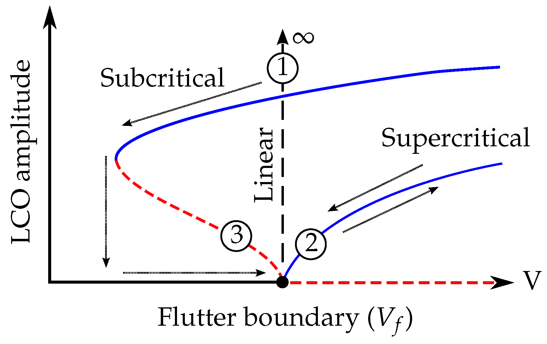
The flutter boundary () of an aeroelastic system is defined as the lowest airspeed at which a small perturbation to a static equilibrium leads to oscillatory motion that does not decay. Thus, it is defined as the lowest airspeed at which the system has a complex-conjugate pair of eigenvalues with zero real part. For linear systems, the dynamics predicted by flutter analysis apply globally and thus any perturbation at leads to a divergent oscillation. However, for nonlinear systems, where linearisation about equilibria is necessary, the dynamics of the perturbation beyond the local region are unknown. As the deformation in the system becomes large, the significant change in structural properties means that the modal interactions necessary for flutter may be affected and thus the dynamics are no longer topologically equivalent to the linearisation.
At the flutter boundary itself, there are two distinct possibilities for a nonlinear system. The first comprises a smooth transition to a stable LCO when the critical airspeed is exceeded, the amplitude of which increases from zero for
(
Figure 2 pt. 2). In this case, the nonlinear flutter point coincides with a so-called
supercritical Hopf bifurcation. As noted in, for example, Ref. [
2], this type of bifurcation is beneficial when compared to the linear case (
Figure 2 pt. 1), as the unbounded oscillation is replaced by a ‘benign’ response that is reversible via the reduction of airspeed (see RHS arrows).
Unfortunately, a deleterious case is also possible; a
subcritical Hopf bifurcation may occur, characterised by an unstable LCO branch for
(
Figure 1 pt. 3) and a subsequent periodic fold bifurcation (this type of bifurcation is characterised by the collision of a stable and an unstable LCO and, since LCOs cannot exist at zero airspeed, is guaranteed to occur in aeroelastic systems when the flutter boundary is subcritical). In this case, the system becomes attracted to a large-amplitude branch when
is reached and thus the LCO behaviour can only be removed by reducing the airspeed to below the fold airspeed. This results in a hysteresis loop (see LHS arrows), a phenomenon that has been observed experimentally in a flexible wing in Ref. [
7]. Additionally, the coexistence of two attractors in the airspeed interval between the fold and Hopf bifurcation means that there is a sensitivity to initial conditions in this region (e.g., a large perturbation could push the system into the basin of attraction of the large LCO). A time history showing this can be found in Ref. [
6]). At the precise fold airspeed, there exists a singular half-stable periodic solution.
In order to mitigate subcritical LCO behaviour by design, it follows that it is useful to gain an understanding of how certain wing parameters (e.g., stiffness properties) affect Hopf bifurcation criticality at
. (Indeed, this has been the focus of a few studies [
9,
10].) However, since the generic behaviours shown in
Figure 2 are determined by low-order nonlinearities, it is possible that higher-order nonlinearities can cause additional bifurcations to occur (for example, additional periodic folds at higher amplitudes). Analysis of the LCO branches is thus necessary, as proof of a supercritical Hopf does not rule out the existence of subcritical LCOs.
Since linear flutter techniques do not capture LCO phenomena, nonlinear methods are necessary. Numerical integration (i.e., time-stepping/simulation) has been commonly used for this purpose [
6,
7]; however, this technique is not well-suited for rigorous dynamical analysis, as the dependence on initial conditions means that many simulations at many airspeeds are necessary. Compounded by the fact that damping is small near flutter boundaries, parametric study of LCOs requires exhaustive computation. The method demonstrated in this paper is numerical continuation [
11]. Consider the parameterised nonlinear dynamical system
where
and
are the states and variable parameters in the system, respectively. The method uses a gradient-based, predictor-corrector algorithm to numerically solve for the implicit curve
and thus illustrates how the equilibria solutions of the system (i.e., stationary points of the vector field
f) vary as parameters change. The linear stability of branches is obtained via the inspection of the eigenvalues of the linearised system (i.e., the Jacobian of the nonlinear system). Local bifurcation points, which correspond to topological changes in the system dynamics, are then easily detectable. The continuation of periodic solutions (i.e., LCOs) is achievable when the boundary value problem
is considered, together with some phase condition, where
T is the period of oscillation and
. Typically, collocation methods are used to solve for the orbits, although shooting methods can also be implemented [
12]. The local stability of periodic solutions can be obtained via the inspection of the Floquet multipliers (i.e., eigenvalues of the monodromy matrix). In addition to equilibria and LCOs, the loci of specific bifurcations can also be continued, provided that the requisite set of variable parameters and objective functions is implemented. For the considered aeroelastic system, it will be shown that the two-parameter continuation of Hopf points and periodic folds is a very efficient method for obtaining the sensitivity of dynamics for variations of airspeed and stiffness.
The use of continuation is highly advantageous when compared to integration approaches, as it facilitates a rapid analysis of design space and can reveal solution branches that would otherwise be undetectable. Despite this, the method has seen limited use within the general aerospace industry, although it has yielded significant benefits in the analysis of nonlinear flight dynamics and control (e.g., Ref. [
13]). A recent report on its use in civil aircraft design is provided in Ref. [
14]. Examples of use in nonlinear aeroelastics research can be found in Refs. [
10,
15,
16]. AUTO [
17] is the most well-known implementation (for an example, see Ref. [
18]), although throughout this study COCO [
19] is used.
4. Bifurcation Results
The purpose of this paper is to demonstrate the applicability of numerical continuation to the nonlinear analysis of highly flexible, high-aspect-ratio wings. As previously noted, linear, quasi-steady aerodynamics are chosen to allow the significant complexities arising from geometric nonlinearity to be demonstrated in isolation. This section describes results obtained using the numerical techniques discussed in
Section 2 together with the aeroelastic formulation in
Section 3. Numerical integration of the system is also used to verify continuation results by illustrating selected dynamical behaviour and showing the presence of hysteresis. The effect of varying parameters corresponding to out-of-plane, in-plane and torsional stiffness (
,
and
, respectively) is investigated via the two-parameter continuation of Hopf points and periodic folds; in each case, parameters not varied are held at the nominal values shown in
Table 1. A stiffness coupling factor (
K) is then implemented between
and
and the effect of varying this parameter is similarly shown.
4.1. Nominal Wing Stiffness Parameters
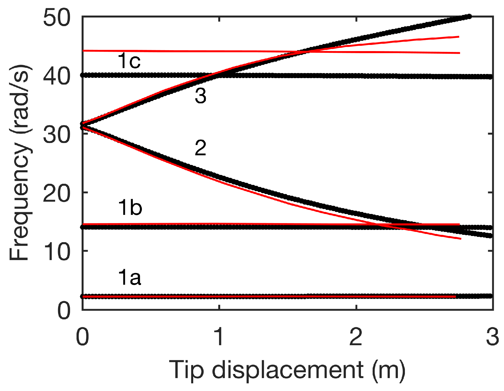
The dynamics of the nominal wing configuration (as per
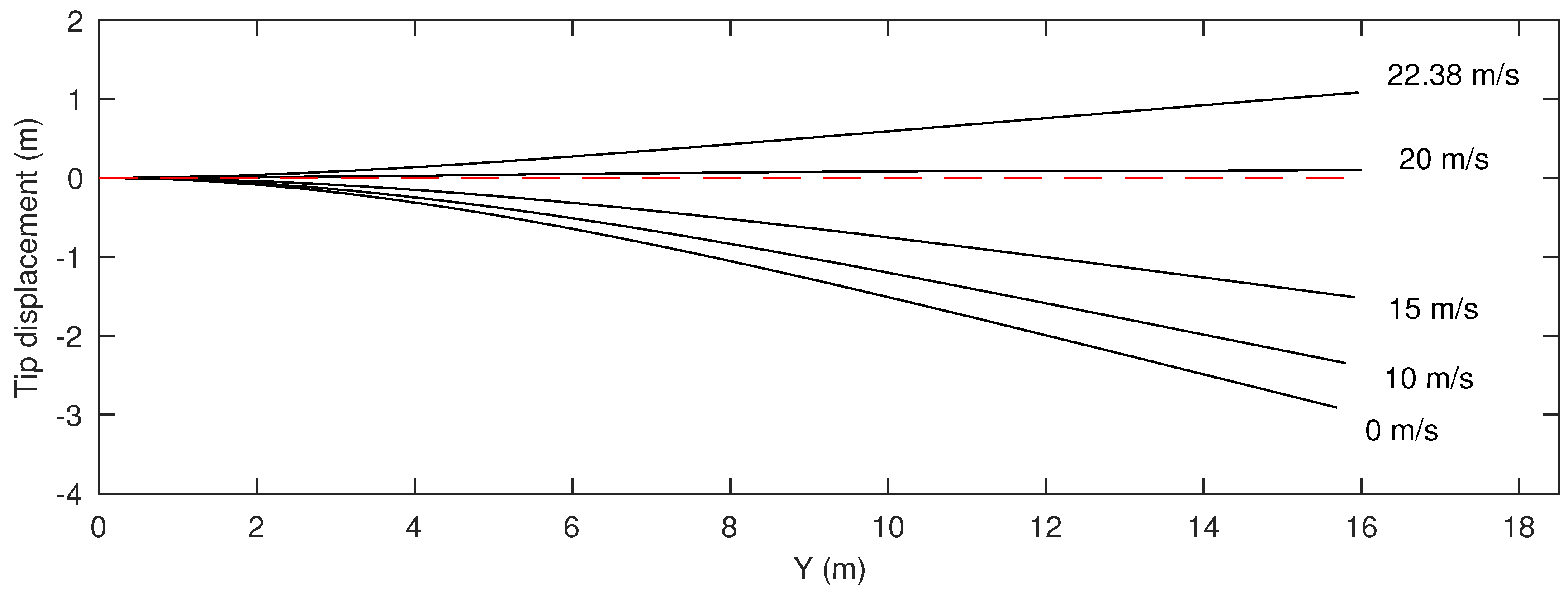
Table 1) are first obtained. Numerical integration of the system is initially used to find a number of steady deflected wing shapes at increasing subcritical airspeeds (
Figure 4).
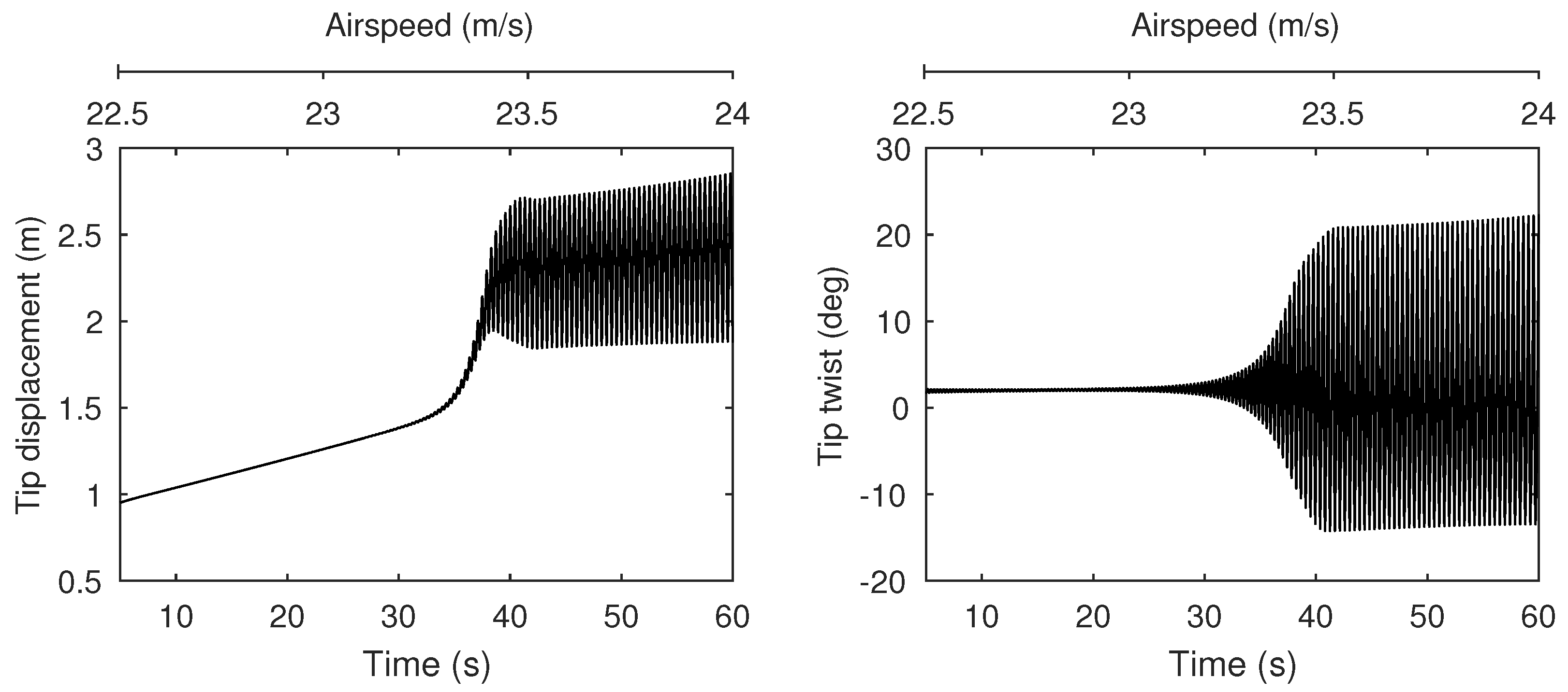
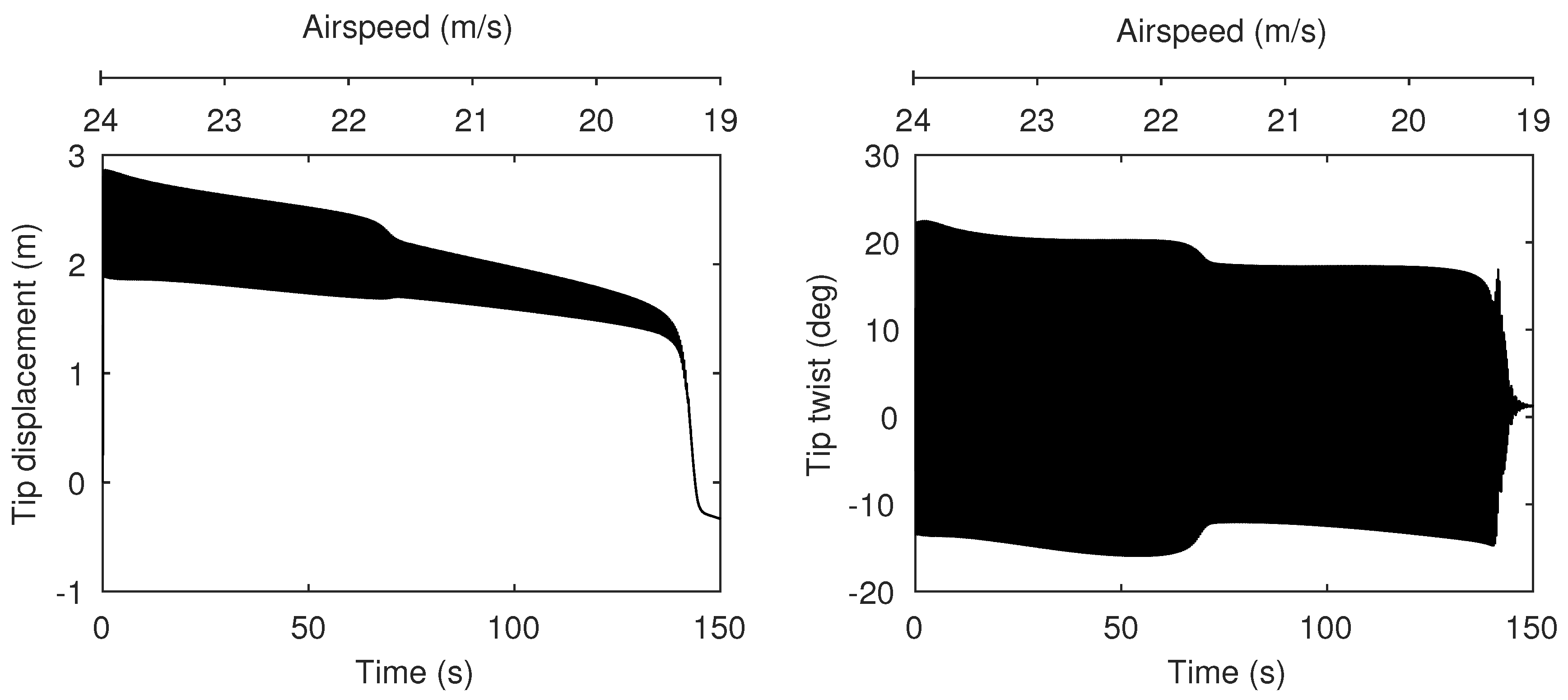
Figure 5 shows the response of the wing to a gradual airspeed ramp (22.5 m/s–24 m/s) and reveals the emergence of an LCO. The growth of the LCO amplitude is rapid, indicating the presence of a subcritical Hopf bifurcation.
Starting from one of the static solutions shown in
Figure 4, one-parameter numerical continuation is now used.
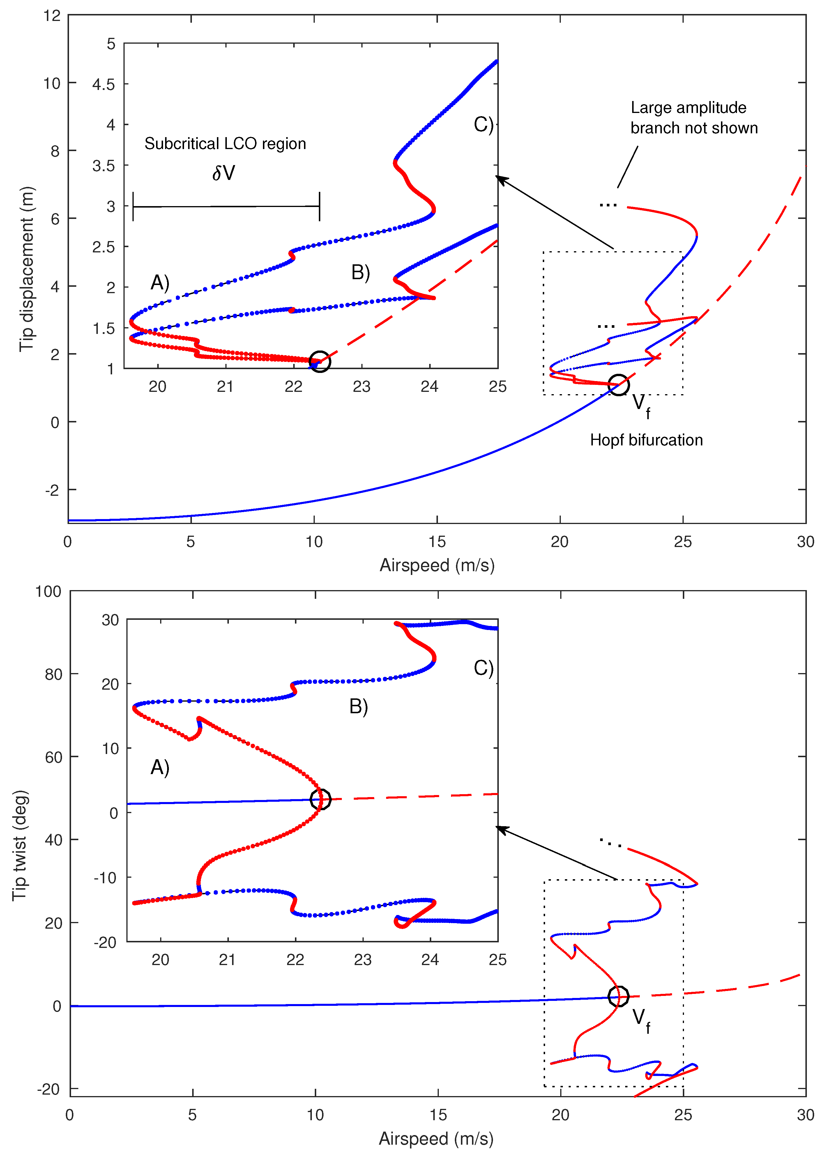
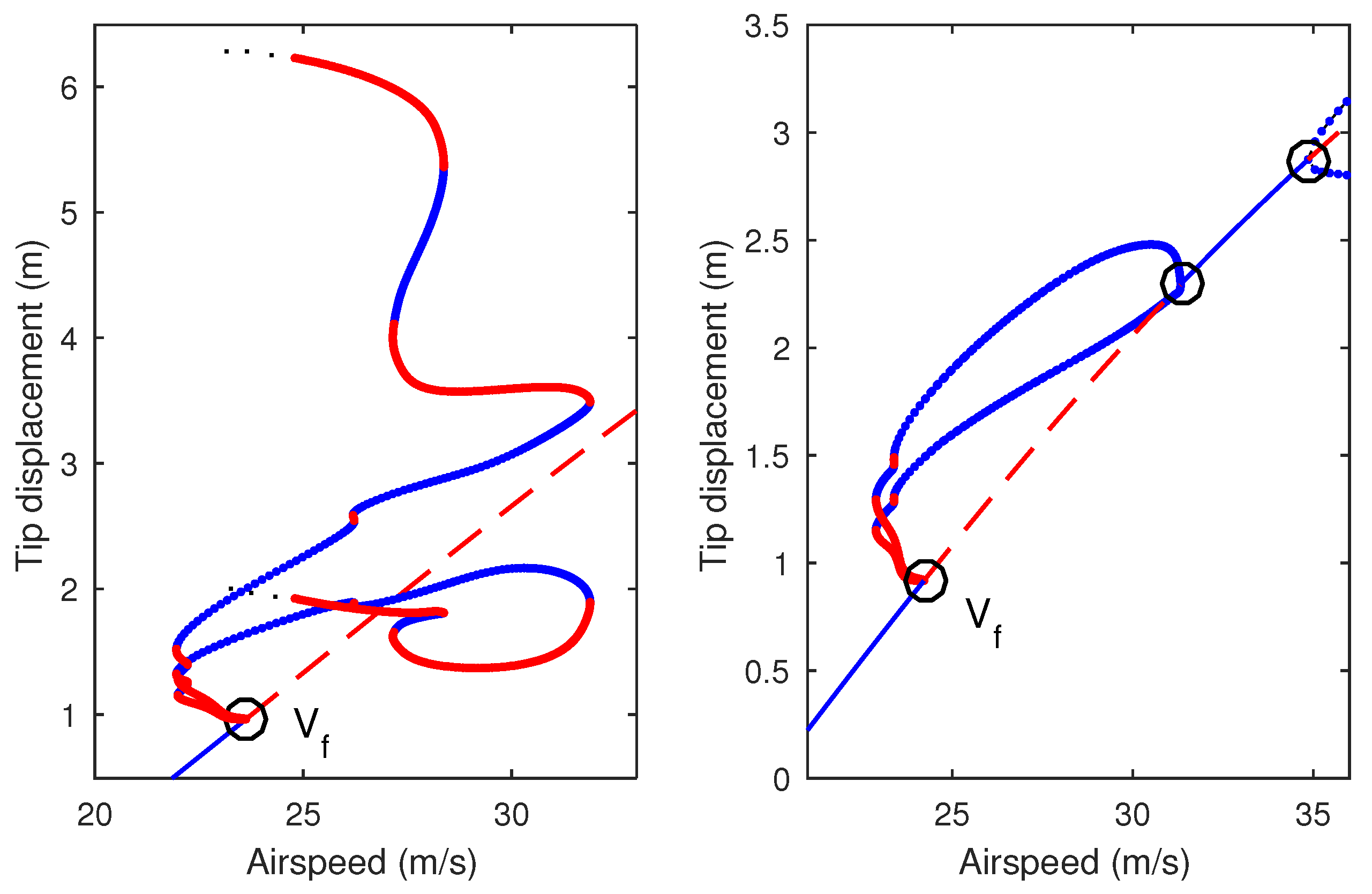
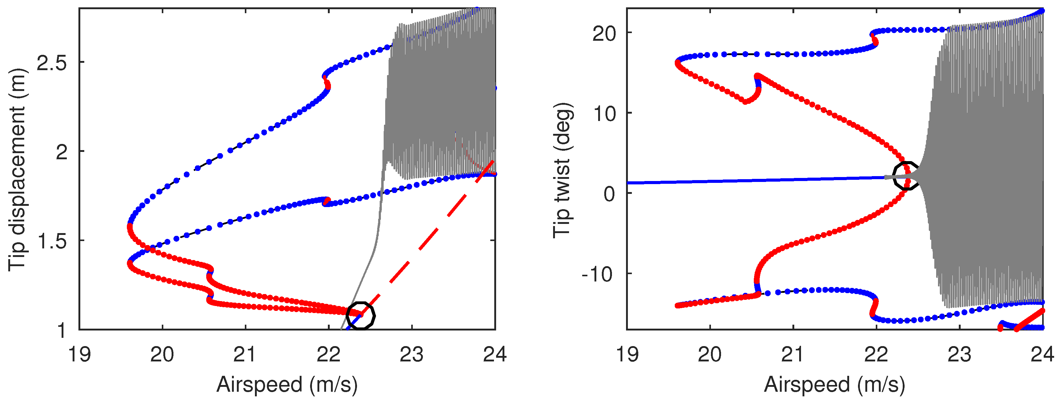
Figure 6 contains the continuation of equilibria and LCOs as airspeed varies and plots solutions in terms of vertical tip displacement (upper panel) and tip twist (lower panel). The minimum and maximum of LCOs are shown. For low airspeeds, a single branch of stable equilibria exists, the magnitude of which increases steadily as airspeed increases (as per
Figure 4). This branch undergoes a Hopf bifurcation and becomes unstable at 22.38 m/s. At this point, which is labelled
to indicate the nonlinear flutter boundary, the tip displacement is 1.08 m and the tip twist is 2.01 deg. (
at tip = 6.98 deg.). The bifurcation is subcritical, as is demonstrated by the emergent unstable LCO. The unstable LCO branch undergoes a number of folds at increasing amplitudes, alternating between unstable and stable solutions, before undergoing a final fold at approximately 25.56 m/s. The resulting unstable branch subsequently leaves the near-flutter region and is not plotted beyond this point (it is found that the resulting LCOs comprise very large wing deformations; the branch is actually seen to extend back to ≈ 6 m/s before folding back to a stable branch with very large amplitude).
Figure 7 illustrates the time histories from
Figure 5 superimposed onto the corresponding continuation branches in
Figure 6. It can be seen that the numerical integration is a good approximation to the continuation result, although transient effects (due to the airspeed ramp) prevent the LCO amplitudes from settling.
The continuation solutions in
Figure 6 show that subcritical LCOs are present near the equilibria for airspeeds as low as 19.61 m/s and thus the subcritical LCO region,
(defined as the airspeed interval between the Hopf and the lowest-airspeed fold, as shown in the figure), is equal to 2.77 m/s. A useful metric is the ratio
, which quantifies this region relative to the nonlinear flutter boundary and in this case is equal to 0.124.
Figure 8 shows the wing response when a decreasing airspeed ramp is applied to the final state of the time history shown in
Figure 5. In this reversed case, the LCO is sustained below
and thus demonstrates the hysteresis in the system.
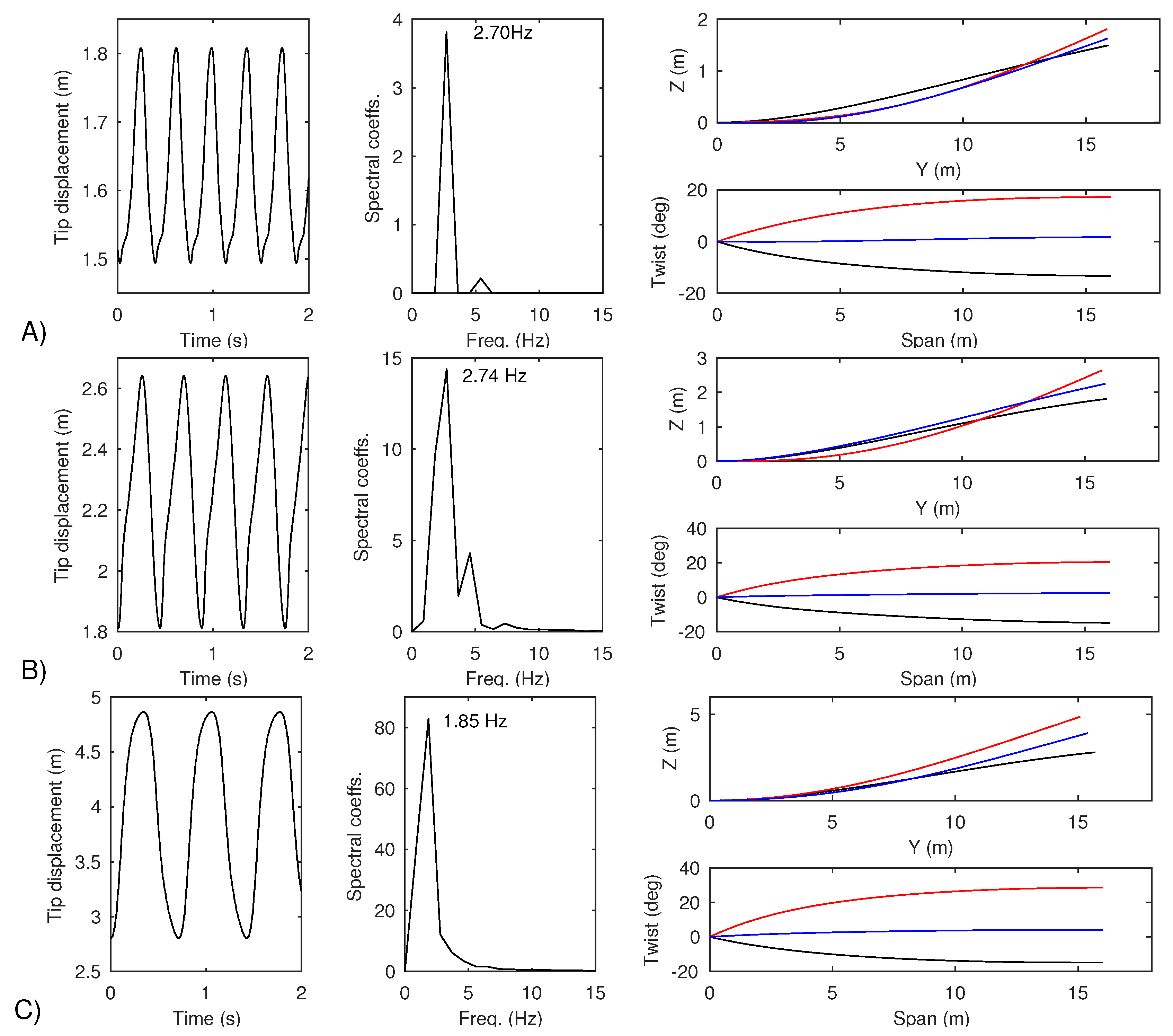
The characteristics of individual LCOs located at selected points on
Figure 6 are now shown.
Figure 9 shows a time history, frequency decomposition and spanwise deformation for each of the solutions at points A (20 m/s), B (23 m/s), and C (25 m/s). The LCOs at 20 m/s and 23 m/s approximate the 2nd out-of-plane bending mode, whereas the larger LCO at 25 m/s approximates the first bending mode. In all three cases, the first torsion mode is present.
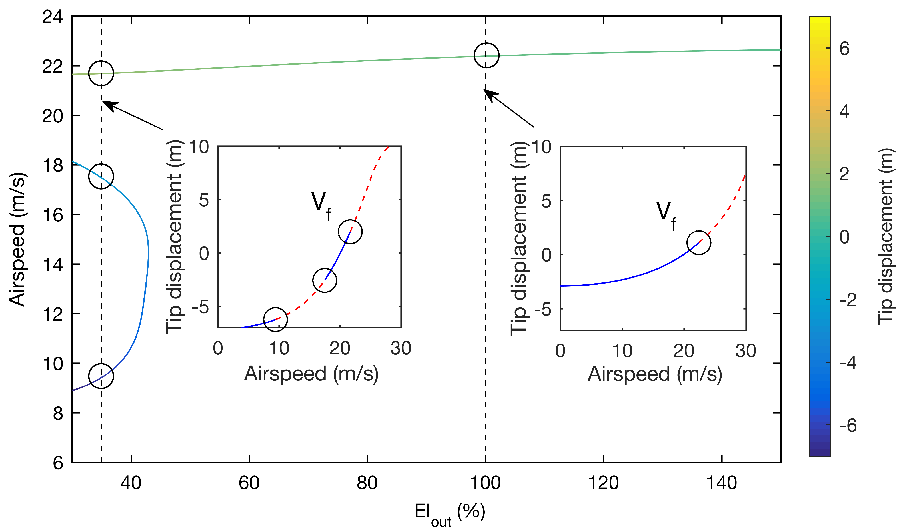
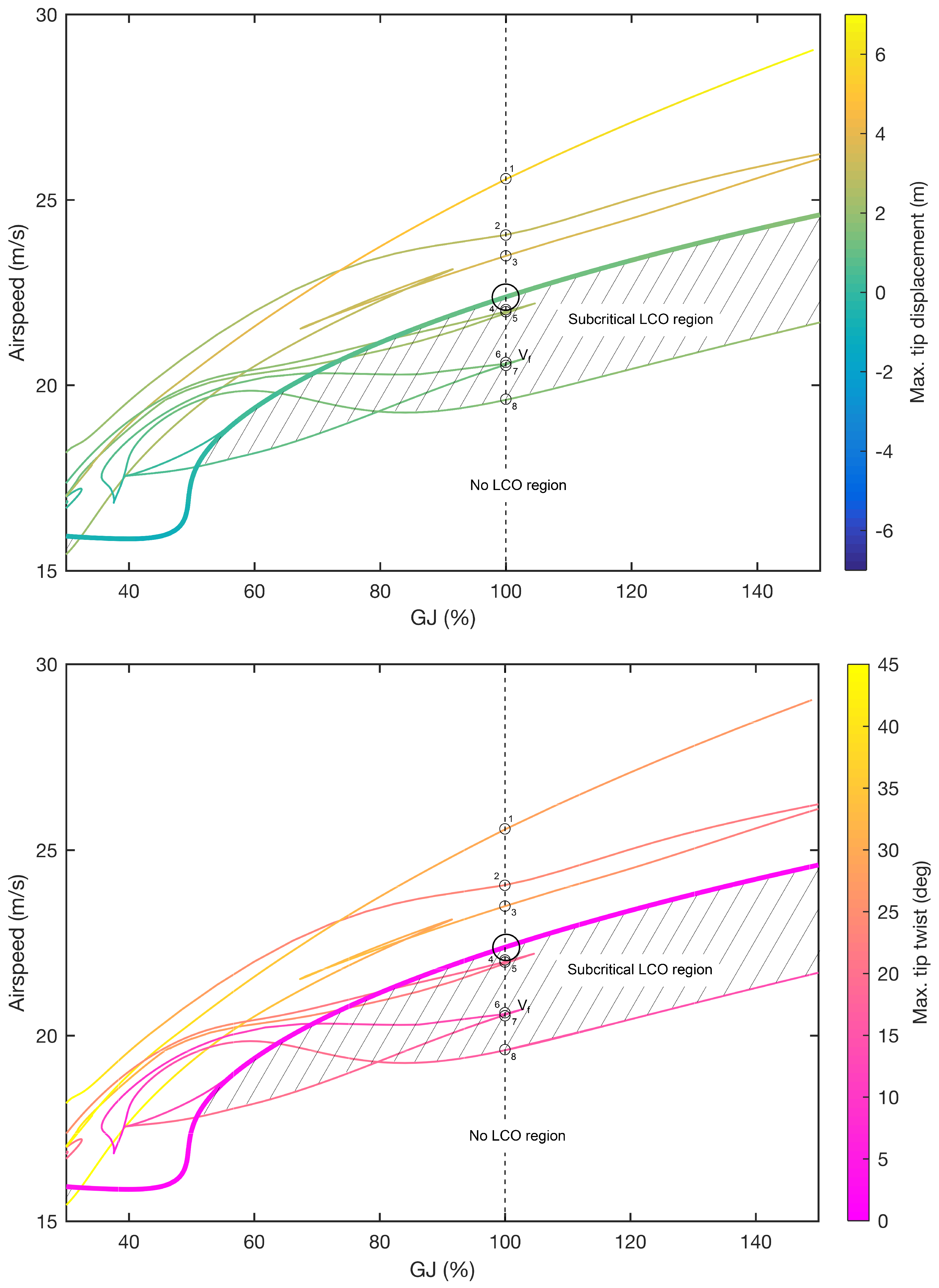
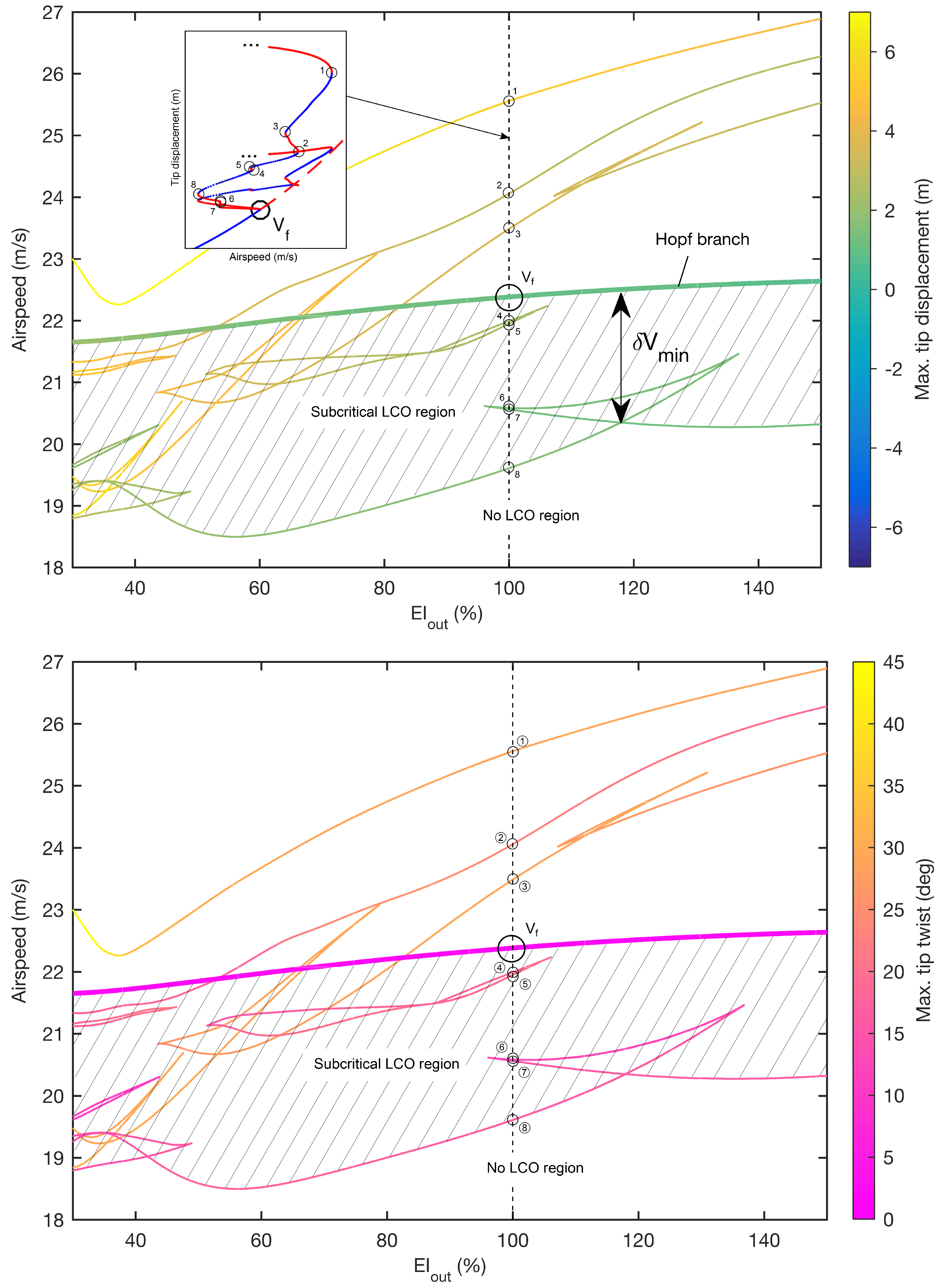
4.2. Variation of Out-of-Plane Bending Stiffness ()
The effect of varying out-of-plane bending stiffness (
) is now demonstrated using two-parameter continuation. The Hopf bifurcation shown in
Figure 6 is continued with respect to both
and airspeed and thus the locus of
for varying stiffness values is directly obtained (
Figure 10). It can be seen that neither decreasing nor increasing
significantly affects the airspeed of the main Hopf branch; however, an additional low-speed branch exists within the system for stiffnesses below ≈ 45% of the nominal value.
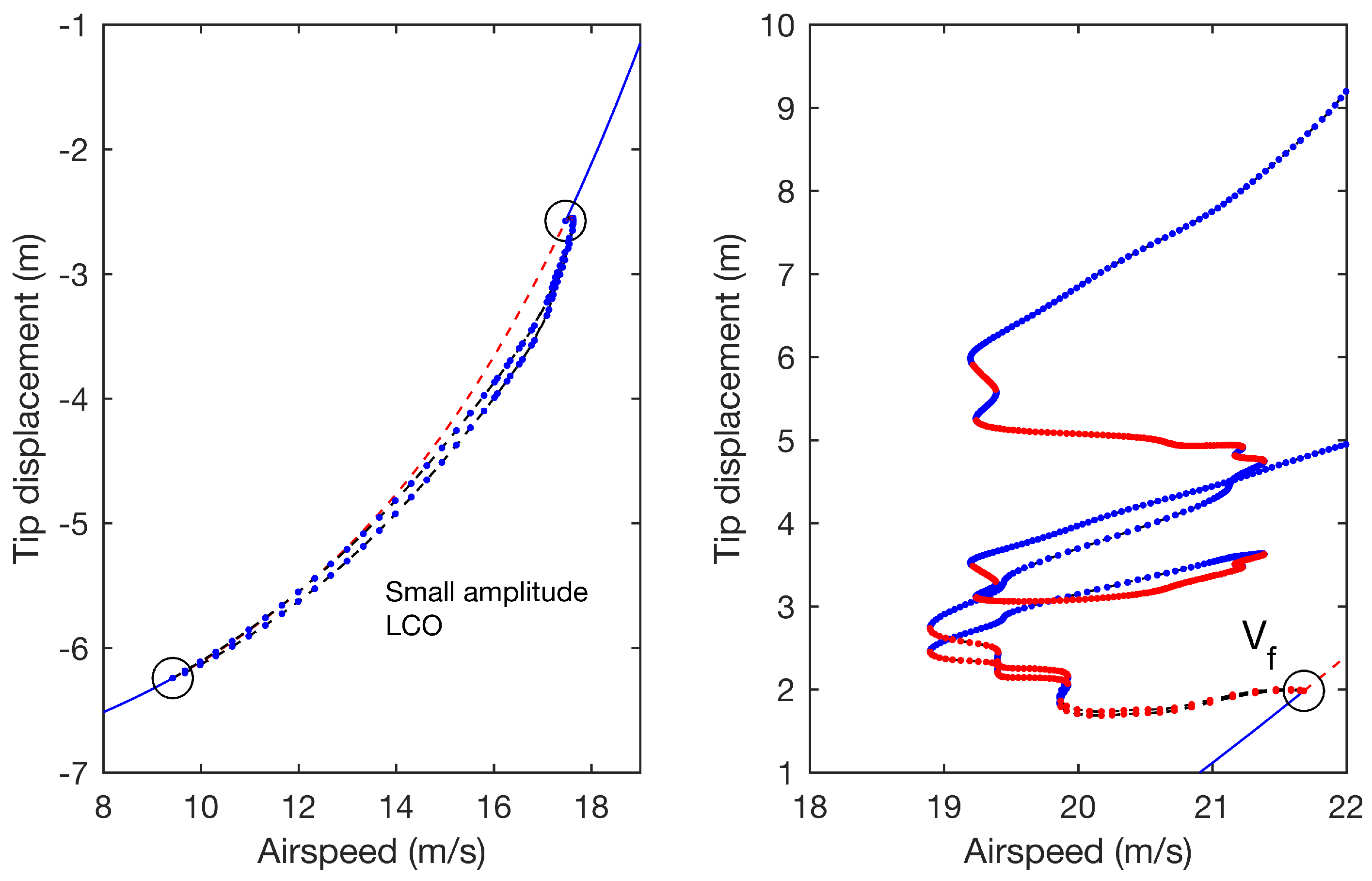
One-parameter continuation at 35%
(
Figure 11, left panel) reveals that the LCOs emanating from these low-speed Hopf points are small amplitude and disappear as airspeed increases. It is found that removing gravity from the system removes these phenomena, indicating that for low
the large negative out-of-plane deformation (due to self-weight) enables destabilising modal interactions to occur at much lower airspeeds. This result is similar to observations made in Ref. [
5], where low-speed instability regions were predicted for cases with low
. In such instances, deformation is similarly dominated by self-weight, but as the result of reduced aerodynamic loading. It is worth noting that use of linearised analysis alone (i.e., without LCO continuation) would see these benign bifurcations as unbounded flutter.
Continuation of the LCOs emanating from
(
Figure 11, right panel) reveals a very complex structure of solution branches, similar to that shown in
Figure 6, although in this case the periodic folds are greater in quantity and mostly occur at airspeeds below the Hopf bifurcation (the final fold at large amplitude is not plotted but is found to occur at 22.4 m/s). This means that, compared to the nominal wing, a greater number of subcritical LCOs exist in the system. However,
0.129, which is similar.
In addition to the continuation of Hopf bifurcations (
Figure 10), two-parameter continuation can also be used to obtain periodic folds. This is a very effective means of building a global picture of the system dynamics, as the variation of the complex LCO structures can be inferred from these solutions. Identifying subcritical LCOs is easily achieved by inspection, via comparison of the loci of folds and the loci of Hopf points. For any given stiffness, a subcritical LCO solution exists if a fold occurs at an airspeed lower than that of the Hopf point.
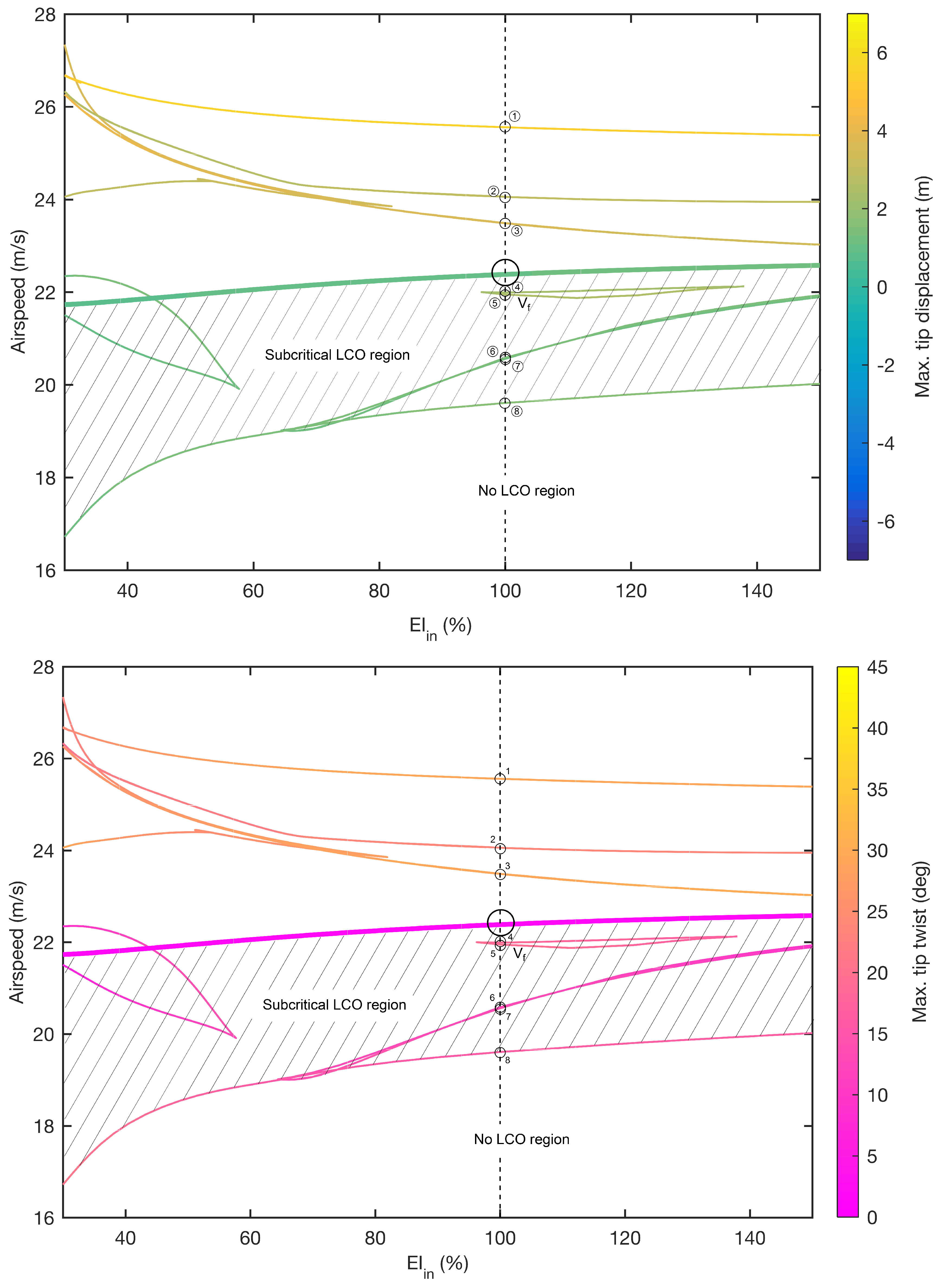
Figure 12 shows the continuation of the periodic folds shown in
Figure 6 and
Figure 11, combined with the main Hopf bifurcation branch from
Figure 10. (The inset shows how the intersections on the vertical plane
relate to the periodic folds shown in
Figure 6). The shaded area between the Hopf branch and the lowest-airspeed folds illustrates the region where LCOs exist at subcritical airspeeds. It can be seen that subcritical LCOs exist at all stiffness values, although the quantity of these solutions increases greatly for lower stiffnesses. A wider range of vertical tip displacements is also achieved at lower stiffness, which is expected given that
is reduced. Stiffening the wing can be seen to yield marginal benefit; increasing
to ≈ 118% achieves the smallest relative subcritical region (
= 0.096), although this is still comparable to that seen for the nominal wing. In all cases, the Hopf bifurcation is found to be subcritical.
4.3. Variation of In-Plane Bending Stiffness ()
Figure 13 shows the continuation of Hopf points and periodic folds over the variation of in-plane bending stiffness (
). As with the variation of
, the Hopf branch is marginally affected, although in this case no other branches are found within the parameter range. The minimum value of
(0.11) is found at the upper boundary of the range and it can be seen that this ratio rapidly increases for
below ≈ 50%. The periodic folds become generally more separated in airspeed as stiffness is reduced, although there is little variation in tip displacement and twist along the branches.
4.4. Variation of Torsional Stiffness ()
Figure 14 shows the continuation of Hopf points and periodic folds for the variation of torsional stiffness (
). Additional Hopf branches are found in the system for low stiffness values, although in all instances these occur at very large tip deflections and are therefore not shown in the figure. It can be seen that varying
has a significant effect on the main Hopf branch. For example, the flutter boundary increases to 24.6 m/s (+9.9%) when
is increased to 150%.
For decreasing stiffness, steadily decreases before reaching a critical value, where the branch drops rapidly and levels out. The periodic folds become more densely concentrated, both in airspeed and tip displacement, although some twist values become very high. For values between approximately 32% and 52%, all LCOs exist at airspeeds greater than the Hopf bifurcation, which itself is found to be supercritical at all values below ≈ 60%. This change of Hopf criticality is indicated by the emergence of a new branch of fold solutions.
When stiffness increases, a number of subcritical LCOs disappear from the system, although the remaining solutions follow a trend similar to that of the Hopf branch. There is a single subcritical LCO for values of above ≈ 105%.
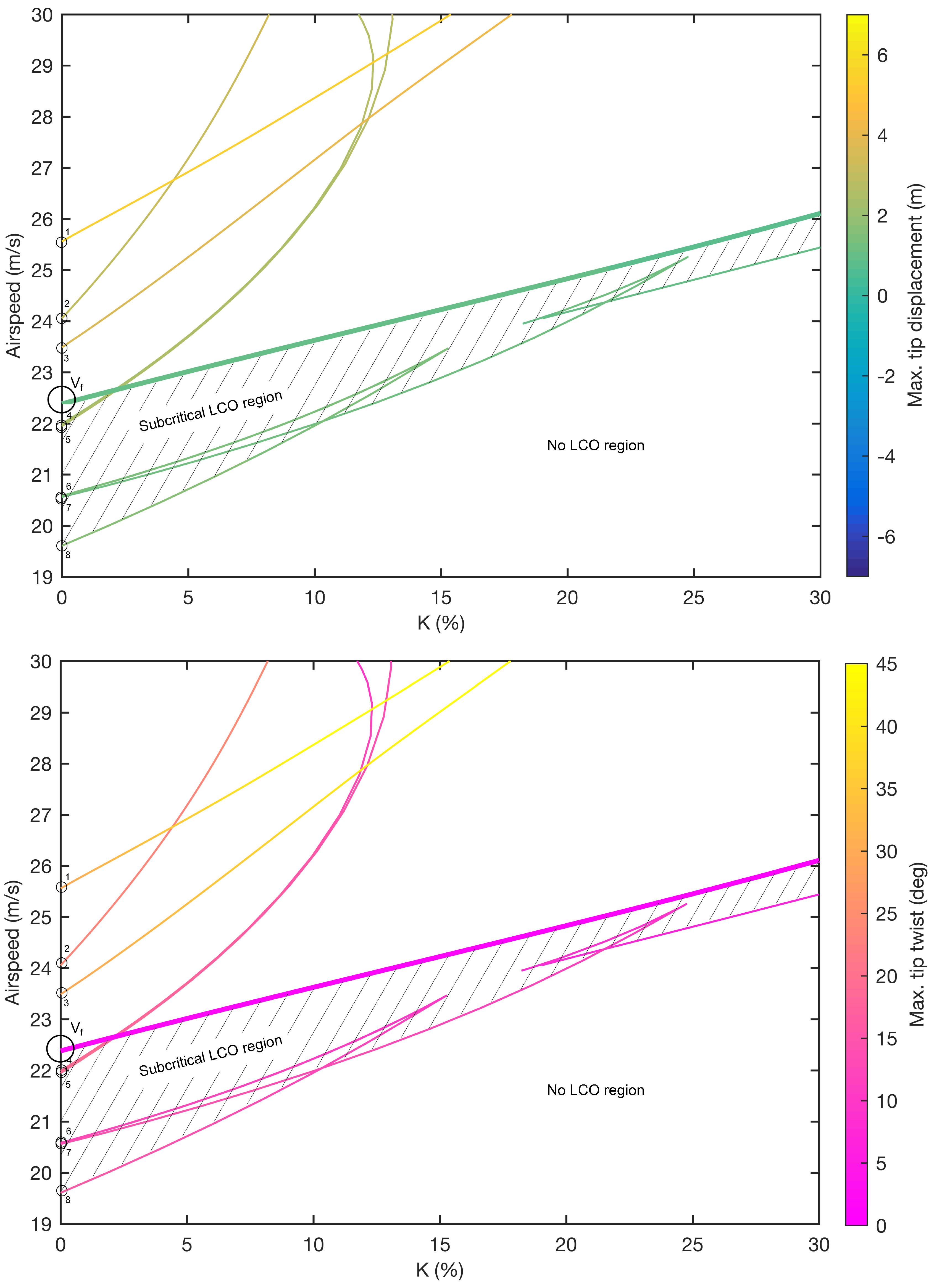
4.5. Variation of Out-of-Plane and Torsional Stiffness Coupling (K)
A stiffness coupling factor (
K) is now applied between
and
. This factor is implemented in off-diagonal elements of the 3-by-3 stiffness matrix of the (Euler–Bernoulli) beam and is expressed as a % of the nominal value of
(as shown in
Table 1). The use of such a term is intended to approximate aeroelastic tailoring techniques that involve the use of directional stiffness properties to provide performance benefit (e.g., gust loads alleviation or flutter suppression; e.g., Ref. [
21]).
Figure 15 shows the continuation of Hopf points and periodic folds for increasing coupling (
K = 0 is the nominal wing). In this study,
corresponds to the case where
increases with out-of-plane deformation, providing a ‘wash-out’ effect. Negative values are not investigated, as these would increase the twisting of the wing. It can be seen from
Figure 15 that the Hopf branch increases in airspeed as coupling increases (for example, at 30% the flutter boundary has increased to 26.19 m/s). Subcritical LCOs exist in the system for all values; however, the region between the lowest-airspeed folds and the Hopf points decreases significantly. At 30%, a single subcritical LCO exists and the subcritical region is reduced (
= 0.037).
Periodic folds occurring beyond the flutter boundary are seen to rapidly increase in airspeed when coupling is increased. Use of one-parameter continuation shows that the overall LCO branch structure undergoes a significant topological change between 10% and 15% (see
Figure 16). During this parameter interval, the LCO branches re-attach to the equilibrium branch, via a second Hopf bifurcation, before a third Hopf point subsequently occurs.
5. Conclusions
This paper demonstrates how numerical continuation can be used to obtain the complex nonlinear aeroelastic dynamics of a highly flexible, high-aspect-ratio wing. A reduced-order nonlinear beam model is used with linear, quasi-steady aerodynamics and one-parameter continuation shows that subcritical limit cycle oscillations (LCOs), which are detrimental solutions existing at airspeeds below the nonlinear flutter boundary, are present due to geometric nonlinearity. The two-parameter continuation of Hopf points and periodic folds reveals the sensitivity of the nominal dynamics to variations in out-of-plane, in-plane and torsional stiffness and a ‘wash out’ stiffness coupling parameter. By the inspection of these complex bifurcation diagrams, regions in parameter space where subcritical LCOs exist are easily identified and it is shown that such phenomena are present for a wide range of stiffness values. Indeed, the only instance where subcritical LCOs do not exist is when torsional stiffness is reduced to 52% of the nominal value. Given this, it is clear that the geometric nonlinearity inherent in highly flexible wings can be a fundamental driver of subcritical behaviour, without the need for aerodynamic nonlinearity. Thus, the effects of large deformations must be adequately treated in the analysis of such wings if undesirable dynamical phenomena are to be mitigated by design.
Current trends in the civil aviation industry indicate that nonlinear aeroelastic analysis will likely play an important role in future wing design. Overall, this paper demonstrates the suitability of numerical continuation techniques for this purpose, particularly when compared to numerical integration approaches, which cannot readily obtain complex dynamics and are thus not well-suited for the parametric analysis of highly flexible wings.

 and
and 


