
Aerial Target Tracking Algorithm Based on Faster R-CNN Combined with Frame Differencing

College of Automation Engineering, Nanjing University of Aeronautics and Astronautics, 29 Jiangjun Road, Nanjing 210016, China
*
Author to whom correspondence should be addressed.
Aerospace 2017, 4(2), 32; https://doi.org/10.3390/aerospace4020032
Submission received: 24 April 2017
/
Revised: 25 May 2017
/
Accepted: 12 June 2017
/
Published: 20 June 2017
(This article belongs to the Collection Unmanned Aerial Systems)
Abstract
:We propose a robust approach to detecting and tracking moving objects for a naval unmanned aircraft system (UAS) landing on an aircraft carrier. The frame difference algorithm follows a simple principle to achieve real-time tracking, whereas Faster Region-Convolutional Neural Network (R-CNN) performs highly precise detection and tracking characteristics. We thus combine Faster R-CNN with the frame difference method, which is demonstrated to exhibit robust and real-time detection and tracking performance. In our UAS landing experiments, two cameras placed on both sides of the runway are used to capture the moving UAS. When the UAS is captured, the joint algorithm uses frame difference to detect the moving target (UAS). As soon as the Faster R-CNN algorithm accurately detects the UAS, the detection priority is given to Faster R-CNN. In this manner, we also perform motion segmentation and object detection in the presence of changes in the environment, such as illumination variation or “walking persons”. By combining the 2 algorithms we can accurately detect and track objects with a tracking accuracy rate of up to 99% and a frame per second of up to 40 Hz. Thus, a solid foundation is laid for subsequent landing guidance.
1. Introduction
Unmanned aircraft systems (UAS) have become a major trend in robotics research in recent decades. UAS has emerged in an increasing number of applications, both military and civilian. The opportunities and challenges of this fast-growing field are summarized by Kumar et al. [1]. Flight, takeoff, and landing involve the most complex processes; in particular, autonomous landing in unknown or Global Navigation Satellite System (GNSS)-denied environments remains undetermined. With fusion and development of computer vision and image processing, the application of visual navigation in UAS automatic landing has widened.
Computer vision in UAS landing has achieved a number of accomplishments in recent years. Generally, we divided these methods into two main categories based on the setup of vision sensors, namely on-board vision landing systems, and method using on-ground vision system. A lot of work has been done for on-board vision landing. Shang et al. [2] proposed a method for UAS automatic landing by recognizing an airport runway in the image. Sven et al. [3] described the design of a landing pad and the vision-based algorithm that estimates the 3D position of the UAS relative to the landing pad. Li et al. [4] estimated the UAS pose parameters according to the shapes and positions of 3 runway lines in the image, which were extracted using the Hough transform. Saripalli et al. [5] presented a design and implementation of a real-time, vision-based landing algorithm for an autonomous helicopter by using vision for precise target detection and recognition. Yang Gui [6] proposed a method for UAS automatic landing by the recognition of 4 infrared lamps on the runway. Cesetti et al. [7] presented a vision-based guide system for UAS navigation and landing with the use of natural landmarks. The performance of this method was largely influenced by the image-matching algorithm and the environmental condition because it needs to compare the real-time image with the reference image. Kim et al. [8] proposed an autonomous vision-based net recovery system for small fixed-wing UAS. The vision algorithm detect the red recovery net and provide the bearing angle to the guidance law is discussed. Similarly, Hul et al. [9] proposed a vision-based UAS landing system, which used a monotone hemisphere airbag as a marker; the aircraft was controlled to fly into the marker by directly feeding back the pitch and yaw angular deviations sensed by a forward-looking camera during the landing phase. The major disadvantage of these methods is that the marker for fixed-wing UAS would be difficult to detect given a complicated background, Moreover, the method proposed in [9] could cause aircraft damage when hitting into the airbag. Kelly et al. [10] presented a UAS navigation system that combined stereo vision with inertial measurements from an inertial measurement unit. The position and attitude of the UAS were obtained by fusing the motion estimated from both sensors in an extended Kalman filter.
Compared with on-board system, a small number of groups place cameras on the ground. This kind of configuration enables the use of high-quality image system and supported by strong computational resources Martinez [11] introduce a real-time trinocular system to control rotary wing UAS to estimate the vehicle’s position and orientation. Weiwei Kong conducted experiments on visual-based landing. In [12], a stereo vision system assembled with a pan-tilt unit (PTU) was presented; however, the limited baseline in this approach resulted in short detection distance. Moreover, the infrared camera calibration method was not sufficiently precise. A new camera calibration method was proposed in [13]; however, the detection range was still restricted at less than 200 m within acceptable errors. In 2014, to achieve long-range detection, 2 separate sets of PTU integrated with a visible light camera were mounted on both sides of the runway, and the widely recognized AdaBoost algorithm was used to detect and track the UAS [14].
In all aforementioned studies, recognition of the runway or markers and colored airbags as reference information is selected. In some studies, stereo vision is used to guide UAS landing. In the former studies, direct extraction of the runway or other markers is susceptible to the environment and thus is not reliable. When the background is complex or the airplane is far from the marker, the accuracy and real-time performance of the recognition algorithm are difficult to meet. The use of infrared light and optical filter can increase the aircraft load. In addition, the pixel in the image appears extremely small because the light source is considerably smaller than the aircraft, resulting in a limited recognition distance. The image matching algorithm in stereo vision exhibits complexity and real-time processing is low. Meanwhile, accurate as well as real-time detection and tracking are the main concerns in vision-based autonomous landing because the targets are small and are moving at a high speed.
To address this problem, frame differencing and deep learning are first combined in the current study for UAS landing. Before that, we often use traditional feature extraction methods to identify UAS, like Histograms of Oriented Gradient (HOG)-based, and Scale-Invariant Feature Transform (SIFT)-based, deep learning is rarely used for UAS landing. While it is generally acknowledged that the effect is not satisfactory. The development of deep learning breaks through the bottleneck of object detection, it compromises accuracy, speed and simplicity. A large number of validation experiments show that, our technique can adapt to various imaging circumstances and exhibits high precision and real-time processing.
2. System Design
2.1. System Architecture
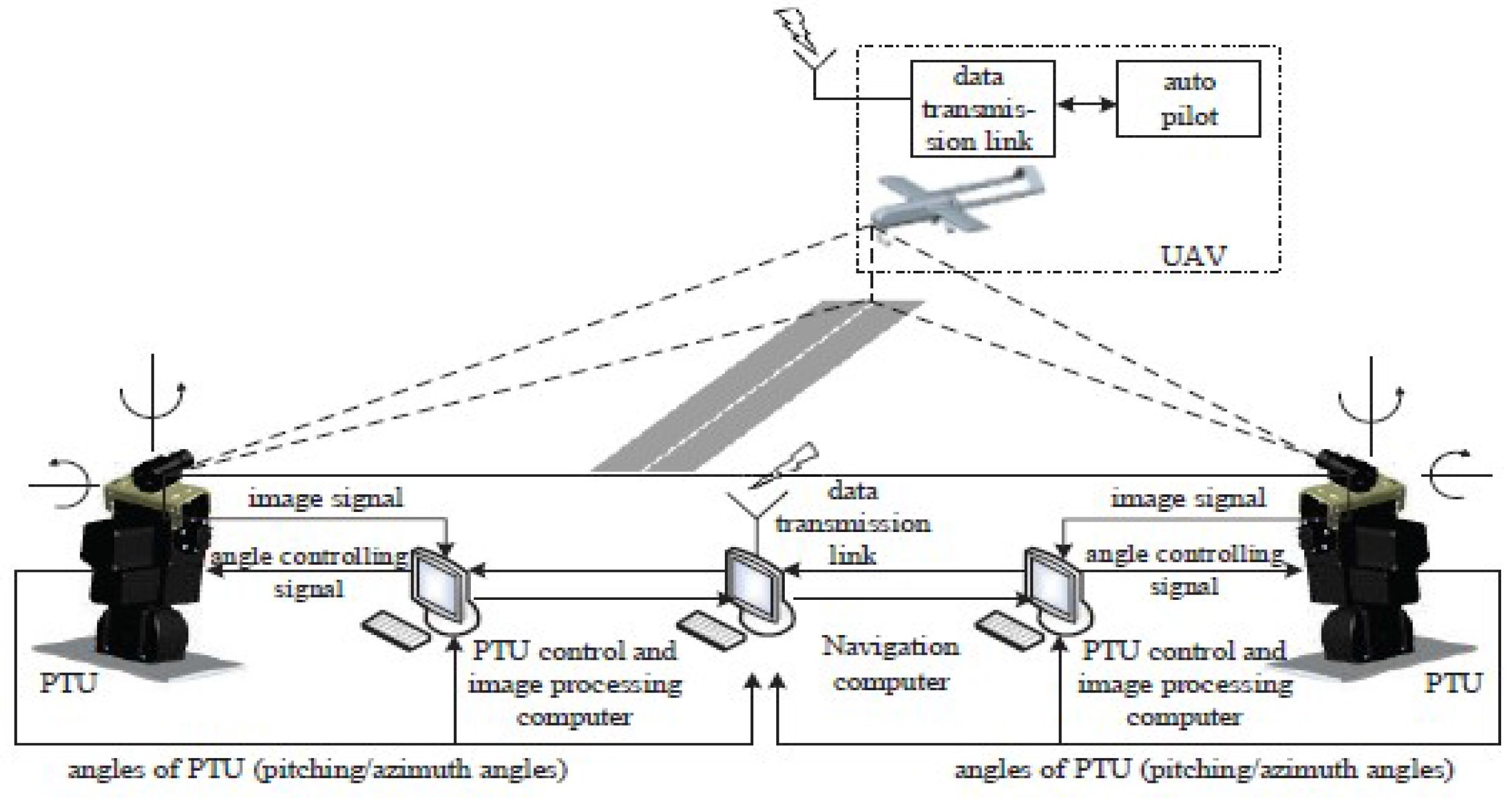
The visual navigation system proposed in this study is composed of 2 tracking subsystems: the target tracking system, which consists of a camera and a high-precision two-axis PTU placed on both sides of the angled deck. The camera is mounted on top of the two-axis PTU, as shown in Figure 1. With the target tracking technology to detect and track the UAS the deflection angle of each PTU is accurately recorded. According to the pitch-and-tilt angle of each PTU and their baseline, the positional relationship between the UAS and ideal landing points can be determined based on the geometric relationship. The relative position data is then sent to the UAS by a wireless data transmission module. Guided by a landing guidance system, UAS glides along the ideal trajectory, and ultimately achieves precise landing. The working flow chart of the whole UAS landing guidance system is illustrated in Figure 2. The most important part of this system is detect the UAS accurately and quickly.
2.2. Experimental Platform
3. Principle of the Proposed Method
A number of studies on object detection and tracking have been conducted in recent years. Regardless, UAS landing based on vision has rarely been performed and remains a challenge. The main detection algorithm currently includes the frame difference, background subtraction, optical flow, and machine learning techniques. The optical flow method is more complex than frame difference and background subtraction, requiring greater computational time and resources than of the other methods. In addition, the technique is vulnerable to environmental factors, not suitable for the outdoors with great illumination changing. Background subtraction is extremely sensitive to changes in light and background, generally assumes the cameras are immobile or only a slight movement. These two methods are not suitable for our scenario. Frame difference approach is simple and easy to implement; however, the results are not accurate enough, given a complex background. Machine learning methods treat tracking as a binary classification problem with a local search algorithm, which estimates the decision boundary between an object image patch and the background. Whereas efficient feature extraction techniques have been proposed for visual tracking, a large number of samples often exist from which features need to be extracted for classification [15]. According to the properties of these methods and our application scenarios, this study presents an improved algorithm that combines frame difference and machine learning with faster region-based convolutional neural network (R-CNN). The algorithm has improved the accuracy of detecting and locating a moving object. With a high detection speed, the proposed technique can perform real-time processing.
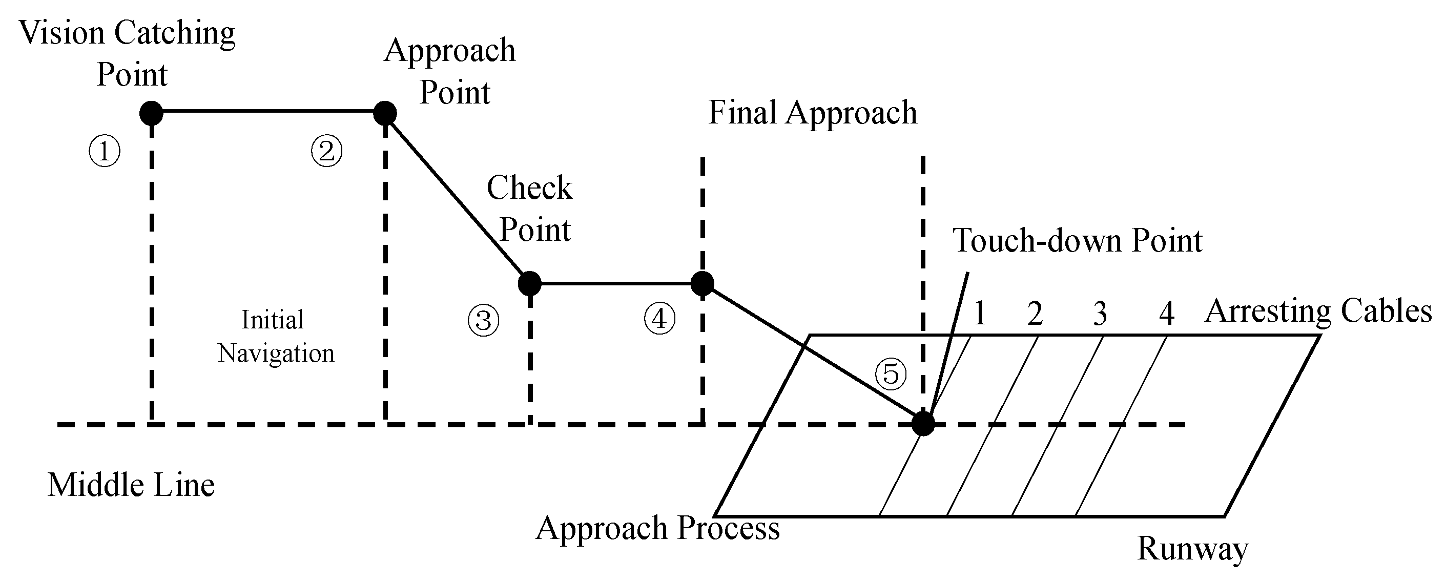
For fixed-wing landing, the process in this study can be divided into 5 phases [14]: (1) UAS being guided by the GPS to the field of view of the camera and then being caught by the vision system; (2) Start of autonomous landing; (3) Checking the relative position and velocity of the aircraft; (4) Final approach; (5) Landing on the ground or hooking the arresting cable. The entire process is illustrated in Figure 4. This study first introduces 2 algorithms for motion detection in fixed scenes: the frame difference method and Faster R-CNN and analyzes their principles and features. A combination of the techniques is then proposed.
3.1. Detection of the Target in the Image
3.1.1. Frame Difference Method
To detect a moving object in a surveillance video captured with an immobile camera, the frame difference method is the simplest technique to employ owing to its high detection speed and ease of implementation on hardware [15].
In the frame difference method a moving object is detected; in the difference images, the unchanged part is eliminated, whereas the changed part is retained. The retained part is caused by target or noises; thus, we set the appropriate threshold to determine whether the retained part is the moving target or noise.
The noise is assumed as Gaussian white noise in calculating the threshold of the binary process. According to the theory of statistics, there is hardly any pixel with a dispersion of more than 3 times that of the standard deviation. Thus, the threshold is calculated as follows:
where represents the mean of the difference image, and is the standard deviation of the difference image. The formula gives a basic selection range, and the actual threshold needs to be adjusted according to the experimental situation.
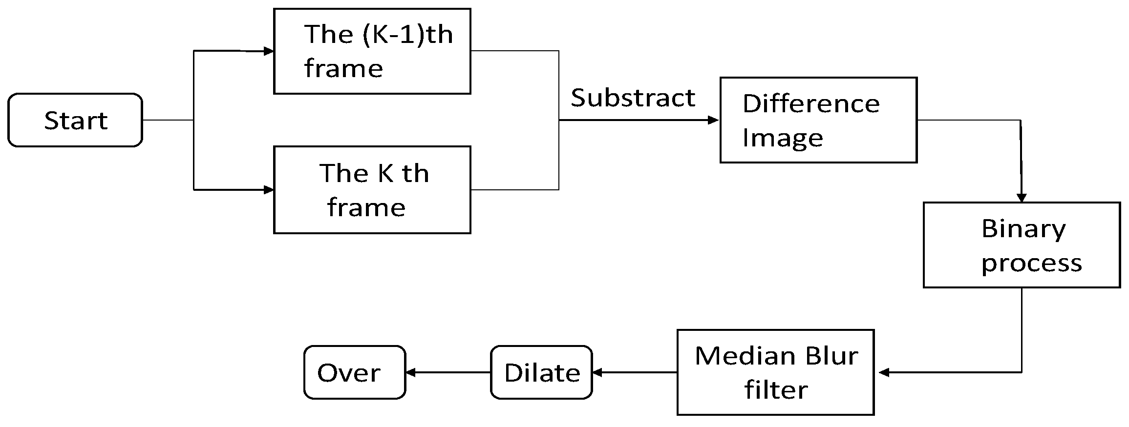
The moving target in the sky is considerably small, so that after difference the target needs to be enhanced. We try several morphological approaches and finally adopt dilation in the program to enhance the target area. A 5 × 5 rectangular structuring element is used for dilation. The flowchart of the detection process by the frame difference method is presented in Figure 5.
For our application background, the cameras are not immobile but drove by the PTU to seek the moving target. Once found, the target is tracked by the camera. When the airplane has just entered the field of view of the camera at a high altitude, the cameras drive by the PTU in the direction of the sky. Most of the background is the sky; thus, we crop the image, use the upper section of the image as the Region of Interest (ROI), and use the frame difference algorithm to locate the target.
3.1.2. Faster R-CNN
Recently, deep convolutional networks have significantly improved the image classification [16] and object detection [17,18] accuracy. Compared with image classification, object detection is more challenging in that it requires real-time and high accuracy. Consequently, many of the existing algorithms fail to meet the requirements. This question has been discussed in detail in Introduction. For our application, when the airplane in the approach process, the background is very complex. To solve this problem, we have tried using many algorithms, including Continuously Adaptive Mean-SHIFT (Camshift) with Kalman Filter and Tracking-Learning-Detection (TLD) [19], HOG-based, and SIFT-based tracking. The Camshift algorithm uses color statistics as a tracking feature, rendering it prone to mistaken identification when the target and background colors are similar. The TLD algorithm is too slow to achieve the purpose of tracking, resulting in poor real-time performance. In HOG + Support Vector Machine (SVM) tracking algorithm, it is difficult to extract effective features when the airplane is far away. As well as the SIFT-based tracking method. In contrast to the above traditional methods, deep learning algorithm is more reliable and accurate, it can quickly detect and localize the UAS from the image. Therefore we choose a state of the art algorithm–Faster R-CNN.
Faster R-CNN is derived from R-CNN. Before R-CNN was proposed, CNN was mainly used for image classification. Unlike image classification, detection requires localizing objects within an image, which is first achieved by R-CNN. CNN can lead to markedly increased objection detection performance on PASCAL VOC relative to systems based on simpler HOG-like features [17]. For image detection, R-CNN can solve the CNN localization problem by operating within the “recognition using regions” paradigm, which has been successful for both object detection and semantic segmentation. This approach is illustrated in Figure 6.
At test time, the algorithm flow is as follows:
- (1)
- The method generates around 2000 category-independent region proposals for the input image;
- (2)
- A fixed-length feature vector is extracted from each proposal by using a CNN;
- (3)
- Each region with category-specific linear SVMs is classified;
- (4)
- Location is fine-tuned.
R-CNN has achieved excellent object detection accuracy by using deep ConvNet to classify object proposals; despite this, the technique has notable disadvantages: The method is too slow because it performs a ConvNet forward pass for each object proposal, without sharing computation. Therefore, spatial pyramid pooling networks (SPPnet) [20] were proposed to speed up R-CNN by sharing computation. The SPPnet method computes a convolutional feature map for the entire input image and then classifies each object proposal by using a feature vector extracted from the shared feature map. In addition, R-CNN requires a fixed input image size, which limits both the aspect ratio and the scale of the image. Current method resize the image to fixed size mostly by cropping or warping, which will cause unwanted distortion or information loss. While SPPnet can pool any size of the image into a fixed-length representation. SPPnet accelerates R-CNN by 10–100× at test time. However, SPPnet has disadvantages. Similar to that in R-CNN, training is a multi-stage pipeline that involves extracting features, fine-tuning a network with log loss, training SVMs, and finally fitting bounding-box regressors. Moreover, the fine-tuning algorithm cannot update the convolutional layers that precede spatial pyramid pooling. This constraint limits the accuracy of very deep networks. An improved algorithm that addresses the disadvantages of R-CNN and SPPnet named, referred to as Fast R-CNN [21] is then proposed, with speed and accuracy enhanced. Fast R-CNN can update all network layers in the training stage and requires no disk storage for feature caching; the features are stored in the video memory.
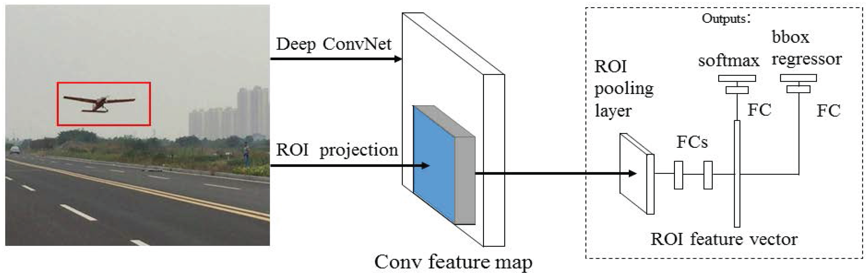
Figure 7 illustrates the Fast R-CNN architecture. The Fast R-CNN network uses an entire image and a set of object proposals as inputs.
- (1)
- The whole image with 5 convolutional and max pooling layers is processed to produce a convolutional feature map.
- (2)
- For each object proposal, a ROI pooling layer extracts a fixed-length feature vector from the feature map.
- (3)
- Each feature vector is fed into a sequence of fully connected layers that finally branch into 2 sibling output layers: one that produces softmax probability estimates over K object classes plus a “background”, and another layer that outputs 4 real-value numbers for each of the K object classes. Each set of 4 values encodes refined bounding-box positions for one of the K classes.
Fast R-CNN achieves near real-time rates by using very deep networks when ignoring the time spent on region proposals. Proposals are the computational bottleneck in state-of-the-art detection systems.
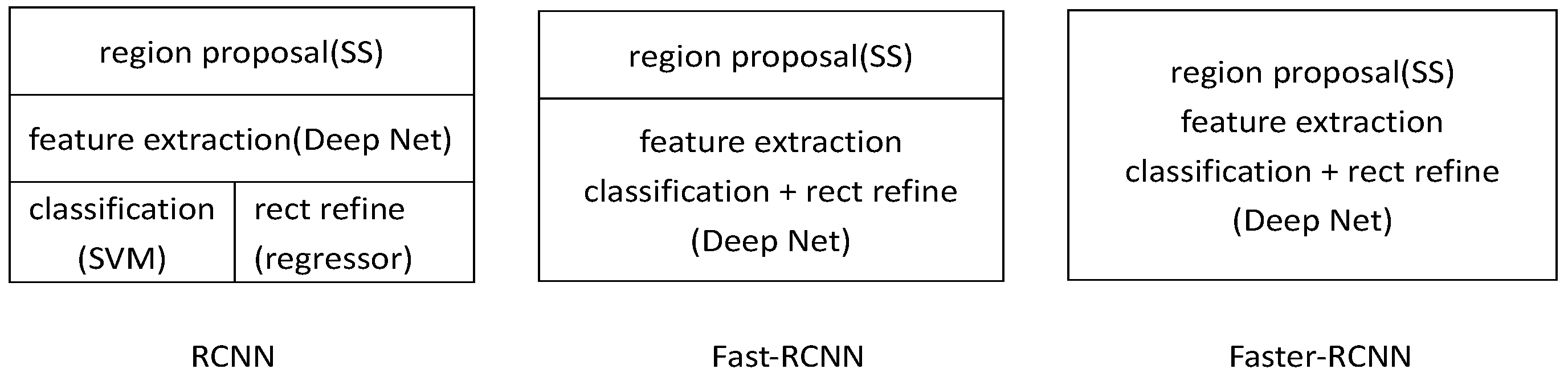
SPPnet and Fast R-CNN reduce the running time of these detection networks, exposing region proposal computation as a bottleneck. For this problem, a new method was proposed, region proposal network (RPN). RPN shares full-image convolutional features with the detection network, thus enabling nearly cost-free region proposal [22]. It is a fully convolutional network that simultaneously predicts object bounds and object scores at each position. RPNs are trained end-to-end to generate high-quality region proposals, which are used by Fast R-CNN for detection. Therefore, Faster R-CNN can be regarded as a combination of RPN and Fast R-CNN. Selective search was replaced by RPN to generate proposals. Faster R-CNN unifies region proposal, feature extraction, classification, and rectangular refinement into a whole network, thereby achieving real-time detection.
The Figure 8 shows the improvement from R-CNN to Fast R-CNN to Faster R-CNN.
3.1.3. Combination of Frame Difference Method and Faster R-CNN
In the landing phase, the UAS is first guided by GPS to the field of view of the camera, as it shown in Figure 4: vision catching point. The camera is then used to capture the UAS. At this time, the background is simple while the target is too small. Extraction of effective feature entails difficulty with Faster R-CNN; thus, we choose the frame difference method to locate the moving target. When the target is detected by Faster R-CNN, the center of the bounding box is compared with that of the center measured by the frame difference technique frame by frame. When the difference is lower than a certain threshold for 5 consecutive frames, the target detected by Faster R-CNN is assumed correct, and the detection algorithm gives priority to Faster R-CNN. The background then becomes increasingly complex, and the frame difference method becomes unsuitable. The whole flowchart is shown in Figure 9.
3.2. Tracking a Target in Sequence Images
For single-target tracking, we make the following improvements on the Faster R-CNN algorithm.
3.2.1. The Highest-Scoring Bounding Box Is Used as the Target
Faster R-CNN was originally designed for multiple target detection, hence the multiple candidates in the output. There is a need to explain the parameter CONF_THRESH, it determines the scoring threshold of output bounding box, that is to say, only the bounding box score larger than CONF_THRESH can be output. When the CONF_THRESH values are set to 0.01 and 0.4, the test results are as Figure 10 (a),(b): the black boxes represent the bounding boxes at the current threshold, and the red box represents the highest-scoring candidate, which is then considered the real target.
3.2.2. Setting ROI for the Next Frame Based on the Previous Bounding Box
Object in the real-world tend to move smoothly through space. It means that a tracker should predict that the target is located near to the location where it was previously observed. This idea is especially important in video tracking. In our landing video, there is only one target, when the detection algorithm identify the target correctly in 5 consecutive frames, we set the ROI for the next frame.
To concretize the idea of motion smoothness, we model the center of ROI in the current frame equal to top left corner of the bounding box () in the previous frame as:
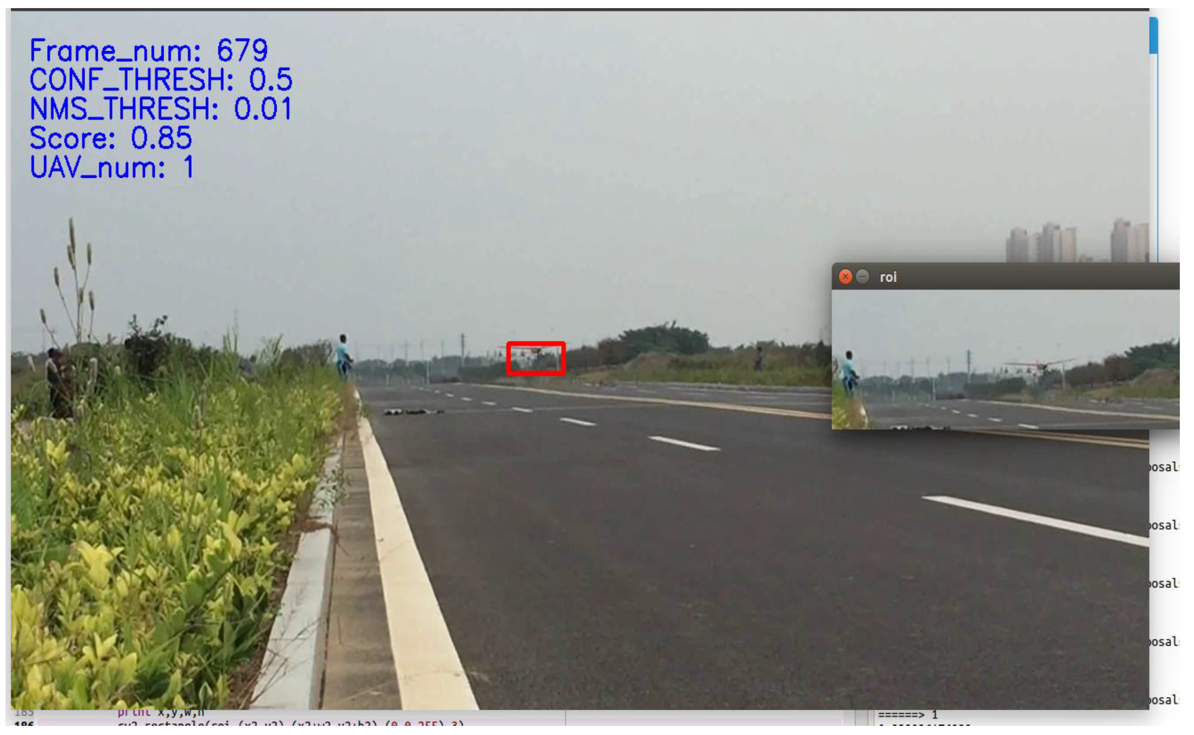
where w and h are the width and height of the bounding box of the previous frame respectively. Frame is the image we get from the camera, the resolution ratio of every frame is 1280 × 720. The term k capture the change in position of the bounding box relative to its size. In our test, k is set to be 4 and we find it gives a high probability on keeping the ROI include the target during the whole landing process. This term should be a variables depend on the target size in the image. In the later experiment, the distance between the target and camera can be calculated, the value of k will depend on this distance. As shown in Figure 11, the red box frames the target, the small image on the right side is ROI, the actual search area of the current frame. It is generated by the target location in the previous frame.
If the current frame does not recognize the aircraft, keep the result of the previous bounding box as the current one, and keep the ROI of the current frame for the next one.
This technique greatly improves accuracy and performance. The experimental results will be discussed in Section 4. In the following, we call this idea ROI-based improved algorithm.
4. Experimental Results and Discussion
A large number of experimental data need to be collected to verify the feasibility of the algorithm. This section describes the test method in detail.
4.1. Experiment Method
As previous mentioned, field testing is crucial. To achieve convincing flight data, we choose a runway about 600 m long and about 15 m wide in Zhenjiang, China. We collect several landing videos taken in Ji’an, China, which has an 800 m runway with a width of 20 m, and in Nanjing, China, a 300 m × 300 m playground. To verify the stability of the algorithm under various conditions, we collect the landing videos under different weather conditions, times, and backgrounds.
We selected visual light camera MV-VDM120SM/SC (Microvision, Suzhou, China), the sensor of this camera has the focal length 16 mm, viewing angle of 16. The experimental results show that the camera can detect the UAS at distances up to 700 m.
To ensure data quality, we select a sample for every 10 frames in different videos. To enhance the richness of the data, we rotate the collected samples and adjust the brightness to generate more samples. Finally, we choose 1659 images as the training set. The Faster R-CNN algorithm requires the data set to be in a VOC2007 data format. We choose Caffe [23] as the training framework. Caffe is a deep learning framework, which was developed with expression, speed, and modularity considered by the Berkeley Vision and Learning Center (BVLC) and community contributors.
4.2. Experimental Results
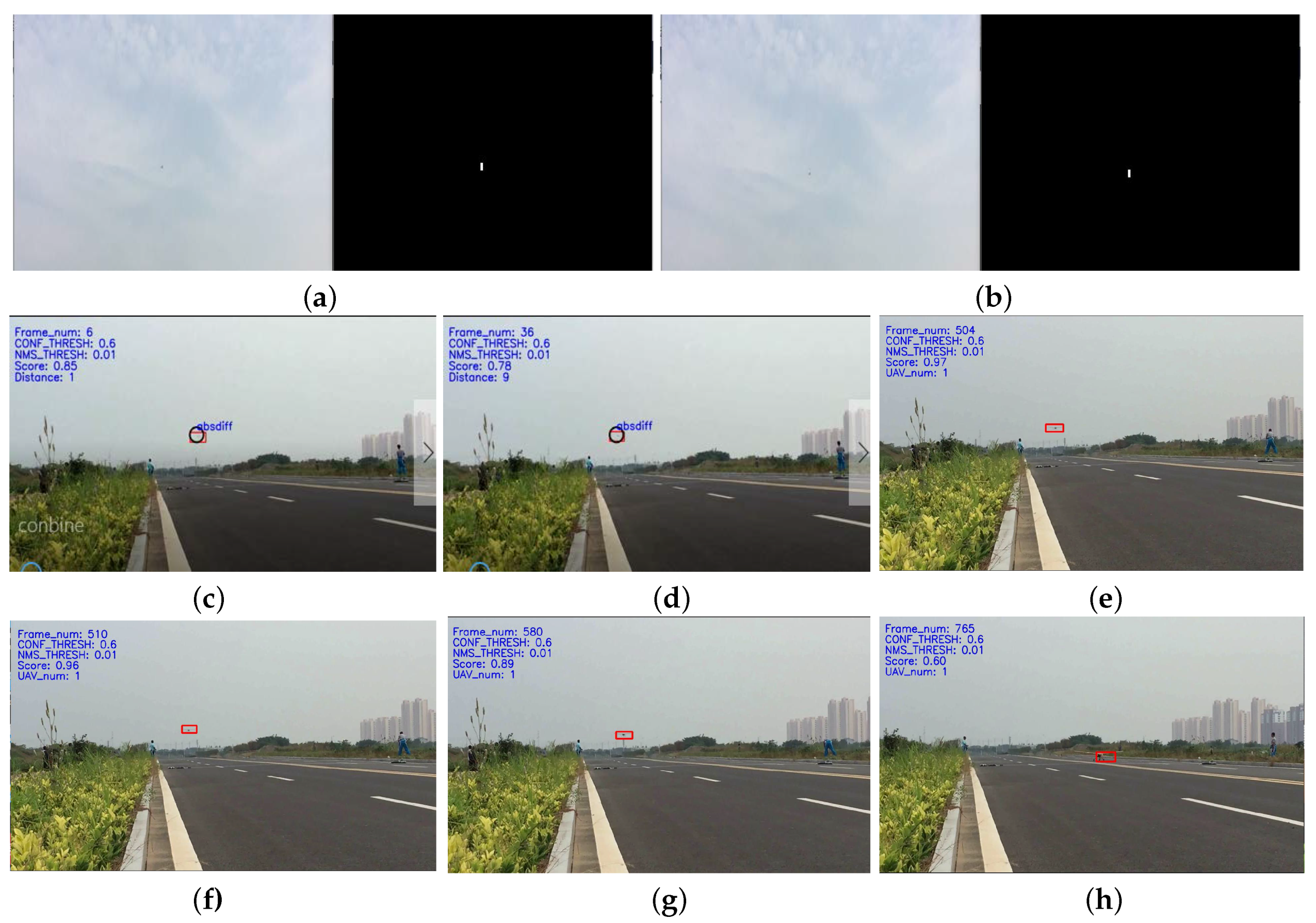
We collected 35 landing videos for testing our combined algorithm, and the results show that high recognition rate can be achieved and the real-time requirements can be satisfied by this algorithm. The target centers are tracked, and their image coordinates are obtained in sequence images. The sequence images of UAS landing processed are shown in Figure 12. There is a need to explain that the colors of the original images in Figure 12 have been inverted for printing convenience. The size of the image is resized to 1280 × 720. The UAS is continuously close to the camera during the landing process; thus, the target size gradually increases in the sequence images.
A series of images in Figure 12 are acquired chronologically for the landing video. For the sake of discussion, all of these images taken with the camera placed on the left side of the runway. After verification, the recognition rates of the images captured by the right camera are almost equivalent to those of the left. A total of 8 frames are taken. The first 2 frames describe UAS detected by the frame difference. We only set the upper half of the image as the ROI. The real environment of the UAS carrier landing has a simple background; thus, this verification method is feasible. The candidate regions of the foreground are detected by the frame difference method, and the real target is detected by threshold segmentation. Dilation is performed to enhance the target, the target region appears enlarged.
Images 3 to 4 are processed using both the frame difference method and Faster R-CNN, and the algorithm has successfully detected the target. The algorithm indicates whether the centers of the target detected by both methods are lower than a certain threshold for 5 consecutive frames. The target detected by Faster R-CNN is assumed to be correct, and the detection algorithm give the priority to Faster R-CNN. In Figure 12, the black circle represents the detection result of the frame difference technique, and the red bounding box represents Faster R-CNN.
Images 5 to 8 are processed only by Faster R-CNN. As illustrated in the figure, the algorithm has a high recognition rate. The touch down time is extremely short; thus, the training samples in this phase are relatively small. In addition, the arresting hook beside the touchdown point may cause disturbance in the detection. The score in this phase is relatively low. However, owing to the improvement based on motion smoothness, the tracking rate has been greatly improved.
4.3. Results Discussion
We evaluate the effectiveness of this combine algorithm from three aspects: accuracy, recognition distance and time performance.
4.3.1. Accuracy
In order to evaluate the accuracy of the detection, some statistical criterion were applied, they are defined as follows. The concept of Confusion Matrix is firstly introduced in Table 2.
(1) Precision
where P means the probability of true positive samples in all positive samples detected by the algorithm. TP is the true positive numbers, it represents the algorithm frames the true positive samples correctly. While FP is the false positive numbers, it means the bounding box don’t frame the target correctly.
(2) Recall
where R means the probability of positive samples detected by the algorithm in all true positive samples. FN is the false negative numbers, in our case, it represents the output bounding box regard target as negatives or has the target omitted.
(3) IoU
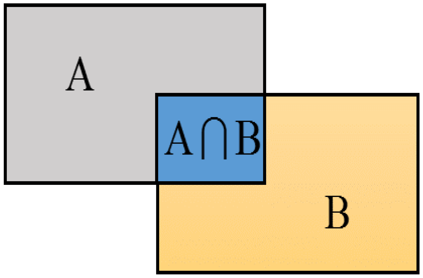
IoU is the abbreviation of intersection-over-union, we use IoU to measure localization performance. As shown in Figure 13, supposed that A represents the ground thuth and B represents the bounding box predicted by the algorithm, A∩B means the intersection part and A∪B is the union part. It is used in the stage of bounding box regression.
In our experiment, we only regard the highest scoring bounding box as result, so the precision and recall values will be equal.
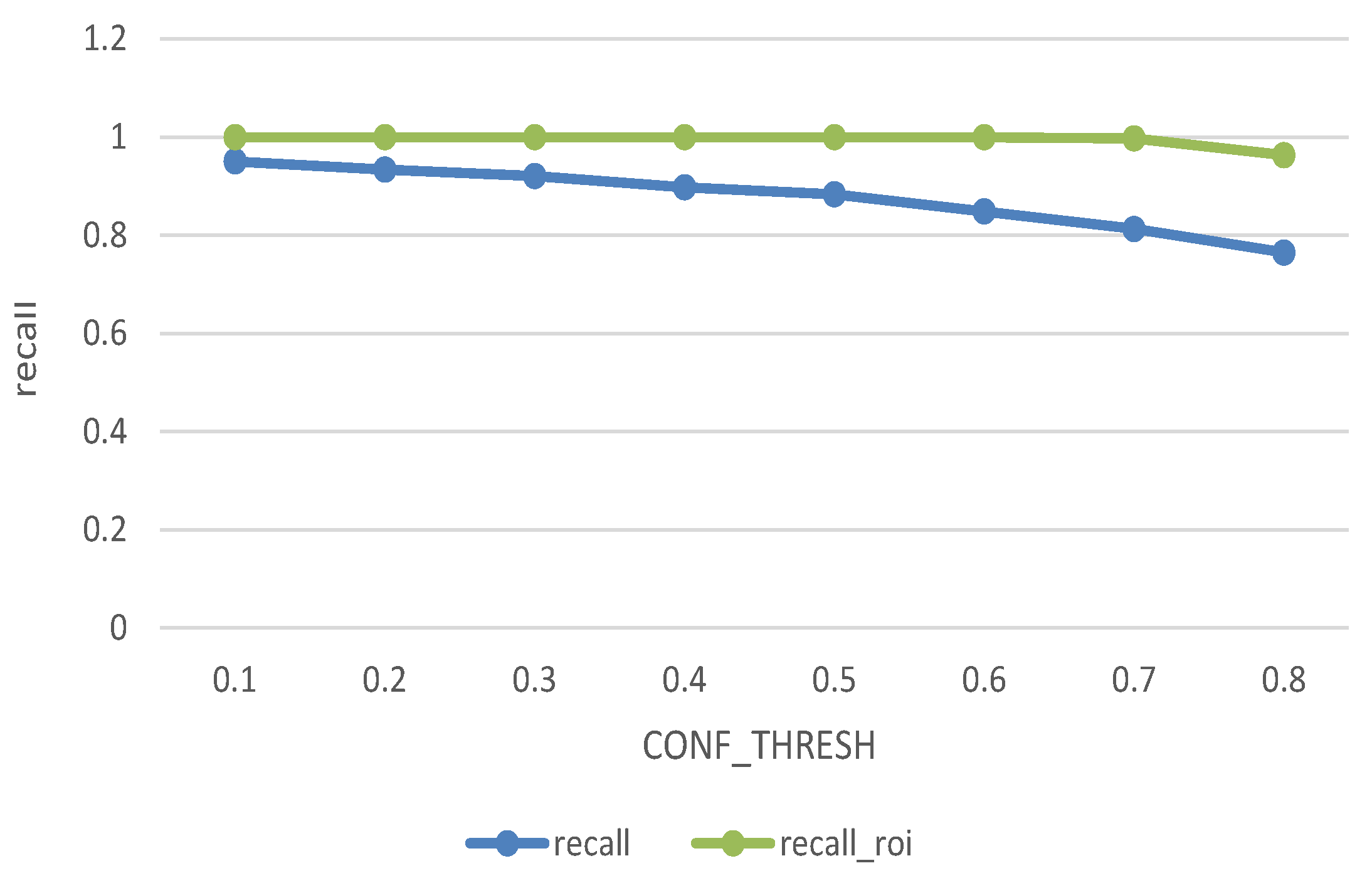
We have 833 samples in the training dataset, and contrast the bounding box predicted by the bounding-box regressor with the ground truth. The blue line and green line respectively show the recall of the original data and the ROI-based processed data under different CONF_THRESH. It can be seen from the Figure 14 that the original recall decrease with the increase of CONF_THRESH, because the true target may be scored lower than CONF_THRESH and be false judged. While after improvement, only when CONF_thresh greater than 0.7, the recall has significantly declined. The ROI algorithm improves the recognition accuracy significantly. In our algorithm we set CONF_THRESH value to be 0.6 and the recall rate after filtering from 88.4% to 99.2%.
Figure 15 gives the relationship between average IoU and CONF_THRESH. IoU is the important measurement of detection accuracy. By calculating the average IoU under different CONF_THRESH to determine the IoU threshold. The figure shows original average IoU maintained between 0.35 and 0.4 and ROI-based improved algorithm has a significant effect on the increasement. Average IoU increased by 0.06. In the final test, we set the IoU thresh to be 0.44. It means when the IoU of bounding box and ground truth larger than 0.44 we assume the algorithm detect the target successfully.
Figure 16 gives the relationship between average IoU and recall. The test shows that the recall of ROI-based improved algorithm up to 99.2% when IoU set to be 0.44.
4.3.2. Detection Distance
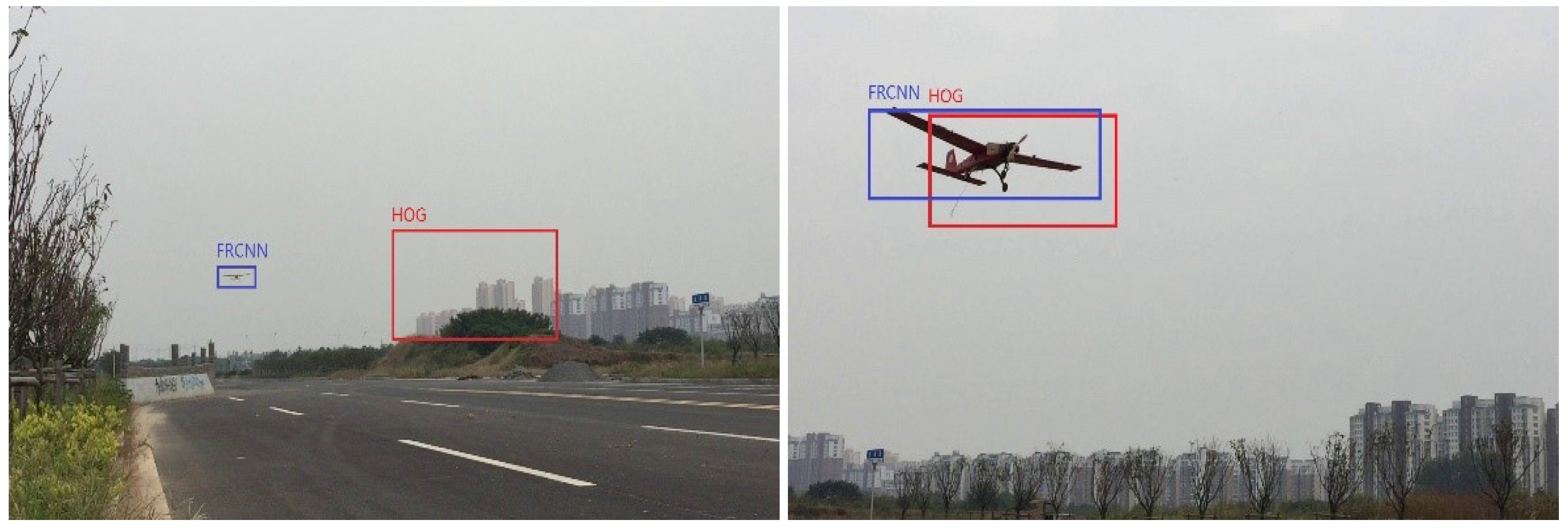
In contrast with traditional algorithm HOG + SVM which achieves good performance on detection, our combined algorithm achieves better results in identification distance.
In HOG + SVM, the detector window is tiled with a grid of overlapping blocks in which Histogram of Oriented Gradient feature vectors are extracted. The combined vectors are fed to a linear SVM for object/non-object classification [24]. From experimental results can be learned that HOG is not good at identifying small target. With limited detection range of 150 m. While our combined algorithm have a valid distance of 700 m. As shown in Figure 17. This is because all samples of HOG + SVM should be unified to the fixed image size, which influences both the aspect ratio and the scale of the target, current method mostly fit the image to the fixed size via cropping or warping. But the cropped region may not contain the entire target, and the warped image may result in geometric distortion. Both of them may influence the recognition accuracy. HOG + SVM algorithm trains out a network that can detect objects, and then sliding the window over the entire picture. Therefore it is difficult to detect the target when target scales vary. However, if the image pyramid has been performed on each image, it will take a long time and has no improvement for ratio changing. Moreover, when the aircraft and the background have similar colors and overlapped, only the gradient information is difficult to identify to UAS. In our experiments, the target has dramatic change in size and ratio, so HOG + SVM only has poor performance.
While in our combined algorithm, frame difference method could detect moving target even if the target is very samll, in case of simple background. Faster R-CNN use anchors to generate proposals. At each sliding-window location, we simultaneously predict k region proposals. The k proposals are parameterized relative to k reference box-anchors [22]. Each anchor is centered at the sliding window, and it associated with a scale and a ratio. Faster R-CNN uses 3 scales and 3 aspect ratios, total 9 anchors at each sliding position. An important property of this approach is translation invariant. So it’s suitable when the object size vary. In addition, the features extracted via CNN is more comprehensive than HOG.
4.3.3. Time Performance
Compared to the original detection algorithm Faster R-CNN, ROI-based improved algorithm were performed for tracking. The speed improvement was shown as follows:
We evaluated the real-time performance on the graphics card GTX1050, applied the idea of motion smoothness into tracking can reduce the search area drastically. As the search area decreases, the number of region proposals can be decreased respectively. As we can see from the Table 3, when work on ROI, the algorithm can achieve 30–40 Hz.
5. Conclusions and Future Work
In this study, we have presented the design and implementation of a real-time vision-based system for tracking a landing target. The vision algorithm is fast, robust, and computationally inexpensive. The proposed method can be realized without the need to install a camera or an image-process device on the UAS. All vision-navigation systems are placed on the ground. Data from 35 flight records indicate that our algorithm performs efficiently, exhibiting accuracy and repeatability. Our experimental materials and source code for the complete system is available at http://pan.baidu.com/s/1bpqzkM7 and I will continue to update all the materials.
Because of the appilication background is landing on the aircraft carrier, our system itself is assumed to be mounted on a ship deck and will inevitably be affected by the deck movement, especially in the longitudinal and lateral motion. In the future, we indent to build an entire visual-based landing system and focus on several points:
- Establish the general deck motion, based on this model, deck motion of various situations can be simulated by changing the size, direction, speed of the ship as well as the sea conditions.
- Design the system of deck motion prediction and compensation. PTU will still drive the cameras to track airplane. It should be noted that when the sea state does not change drastically, PTU have the ability to track the UAV even on the deck, due to deck movement frequency is much lower than PTU tracking frequency. In our study, we use triangulation to calculate the 3D coordinates of the UAS in order to provide landing guidance parameters. During the calculation of target based on triangular, the rotate of PTU caused by deck motion will be removed. Thus the glides path based on PTU reference frame maintain a steady glideslope algorithm. We learn from the idea of digital stabilization platform which has already applied in the instrument landing system (ILS).
Acknowledgments
This work was supported by the Foundation of Graduate Innovation Center in NUAA (Grant NO. kfjj20160316, kfjj20160321).
Author Contributions
This work were carried out by Yurong Yang and Peng Sun, with technical input and guidance from Xinhua Wang and Huajun Gong .
Conflicts of Interest
The authors declare no conflict of interest.
Abbreviations
| UAS | Unmanned Aircraft System |
| GNSS | Global Navigation Satellite System |
| PTU | Pan-Tilt-Unit |
| Camshift | Continuously Adaptive Mean-SHIFT |
| HOG | Histogram of Oriented Gradient |
| SVM | Support Vector Machine |
| SIFT | Scale-Invariant Feature Transform |
| TLD | Tracking-Learning-Detection |
| ROI | Region of Interest |
| Caffe | Convolutional Architecture for Fast Feature Embedding |
| CNN | Convolutional Neural Network |
| R-CNN | Region-Convolutional Neural Network |
| RPN | Region Proposal Network |
| IoU | Intersection over Union |
| ILS | Instrument landing System |
References
- Kumar, V.; Michael, N. Opportunities and challenges with autonomous micro aerial vehicle. Int. J. Robot. Res. 2012, 31, 1279–1291. [Google Scholar] [CrossRef]
- Shang, J.J.; Shi, Z.K. Vision-based runway recognition for UAV autonomous landing. Int. J. Comput. Sci. Netw. Secur. 2007, 7, 112–117. [Google Scholar]
- Lange, S.; Sunderhauf, N.; Protzel, P. A vision based onboard approach for landing and position control of an autonomous multirotor UAV in GPS-denid Environment. In Proceedings of the ICAR 2009 International Conference on Advanced Robotics, Munich, Germany, 22–26 June 2009. [Google Scholar]
- Li, H.; Zhao, H.; Peng, J. Application of cubic spline in navigation for aircraft landing. J. Huazhong Univ. Sci. Technol. Nat. Sci. Ed. 2006, 34, 22–24. [Google Scholar]
- Saripalli, S.; Montgomery, J.F.; Sukhatme, G. Vision-based autonomous landing of an unmanned aerial vehicle. In Proceedings of the 2002 IEEE International Conference on Robotics and Automation (ICRA), Washington, DC, USA, 11–15 May 2002; pp. 2799–2804. [Google Scholar]
- Gui, Y.; Guo, P.; Zhang, H.; Lei, Z.; Zhou, X.; Du, J.; Yu, Q. Airborne Vision-Based Navigation Method for UAV Accuracy Landing Using Infrared Lamps. J. Intell. Robot. Syst. 2013, 72, 197–218. [Google Scholar] [CrossRef]
- Cesetti, A.; Frontoni, E.; Mancini, A.; Zingaretti, P.; Longhi, S. A vision-based guidance system for UAV navigation and safe landing using natural landmarks. J. Intell. Robot. Syst. 2010, 57, 223–257. [Google Scholar] [CrossRef]
- Kim, H.J.; Kim, M.; Lim, H.; Park, C.; Yoon, S.; Lee, D.; Choi, H.; Oh, G.; Park, J.; Kim, Y. Fully Autonomous Vision-Based Net-Recovery Landing System for a Fixed-Wing UAV. IEEE ASME Trans. Mechatron. 2013, 18, 1320–1333. [Google Scholar] [CrossRef]
- Huh, S.; Shim, D.H. A vision-based automatic landing method for fixed-wing UAVs. J. Intell. Robot. Syst. 2010, 57, 217–231. [Google Scholar] [CrossRef]
- Kelly, J.; Saripalli, S.; Sukhatme, G.S. Combined visual and inertial navigation for an unmanned aerial vehicle. In Proceedings of the International Conference on Field and Service Robotics, Chamonix, France, 9–12 July 2007. [Google Scholar]
- Martínez, C.; Campoy, P.; Mondragón, I.; Olivares-Méndez, M.A. Trinocular ground system to control UAVs. In Proceedings of the IEEE/RSJ International Conference on Intelligent Robots and Systems (IROS 2009), St. Louis, MO, USA, 10–15 Octorber 2009; pp. 3361–3367. [Google Scholar]
- Kong, W.; Zhang, D.; Wang, X.; Xian, Z.; Zhang, J. Autonomous landing of an uav with a ground-based actuated infrared stereo vision system. In Proceedings of the 2013 IEEE/RSJ Intelnational Conference on Intelligent Robots and Systems (IROS), Tokyo, Japan, 3–7 November 2013; pp. 2963–2970. [Google Scholar]
- Yu, Z.; Shen, L.; Zhou, D.; Zhang, D. Calibration of large FOV thermal/visible hybrid binocular vision system. In Proceedings of the 2013 32nd Chinese Control Conference (CCC), Xi’an, China, 26–28 July 2013; pp. 5938–5942. [Google Scholar]
- Kong, W.; Zhou, D.; Zhang, Y.; Zhang, D.; Wang, X.; Zhao, B.; Yan, C.; Shen, L.; Zhang, J. A ground-based optical system for autonomous landing of a fixed wing UAV. In Proceedings of the International Conference on Intelligent Robots and Systems, Chicago, IL, USA, 14–18 September 2014; pp. 4797–4804. [Google Scholar]
- Zhan, C.; Duan, X.; Xu, S.; Song, Z.; Luo, M. An Improved Moving Object Detection Algorithm Based on Frame Difference and Edg Detection. In Proceedings of the Fourth International Conference on Image and Graphics, Sichuan, China, 22–24 Augest 2007; pp. 519–523. [Google Scholar]
- Krizhevsky, A.; Sutskever, I.; Hinton, G.E. ImageNet classification with deep convolutional neural networks. In Proceedings of the International Conference on Neural Information Processing Systems, Lake Tahoe, NV, USA, 3–6 Decembe 2012; Curran Associates Inc.: New York, NY, USA, 2012; pp. 1097–1105. [Google Scholar]
- Girshick, R.; Donahue, J.; Darrell, T.; Malik, J. Rich Feature Hierarchies for Accurate Object Detection and Semantic Segmentation. avXiv, 2013; 580–587avXiv:1311.2524. [Google Scholar]
- Sermanet, P.; Eigen, D.; Zhang, X.; Mathieu, M.; Fergus, R.; LeCun, Y. OverFeat: Integrated Recognition, Localization and Detection Using Convolutional Networks. avXiv, 2013; avXiv:1312.6229. [Google Scholar]
- Kalal, Z.; Mikolajczyk, K.; Matas, J. Tracking-Learning-Detection. IEEE Trans. Pattern Anal. Mach. Intell. 2011, 34, 1409–1422. [Google Scholar] [CrossRef] [PubMed]
- He, K.; Zhang, X.; Ren, S.; Sun, J. Spatial Pyramid Pooling in Deep Convolutional Networks for Visual Recognition. IEEE Trans. Pattern Anal. Mach. Intell. 2014, 37, 1904–1916. [Google Scholar] [CrossRef] [PubMed]
- Girshick, R. Fast R-CNN. avXiv, 2015; avXiv:1504.08083. [Google Scholar]
- Ren, S.; He, K.; Girshick, R.; Sun, J. Faster R-CNN: Towards Real-Time Object Detection with Region Proposal Networks. IEEE Trans. Pattern Anal. Mach. Intell. 2016, 39, 1137–1149. [Google Scholar] [CrossRef] [PubMed]
- Caffe. Available online: http://caffe.berkeleyvision.org/ (accessed on 24 April 2017).
- Dalal, N.; Triggs, B. Histograms of oriented gradients for human detection. In Proceedings of the 2005 IEEE Computer Society Conference on Computer Vision and Pattern Recognition (CVPR), San Diego, CA, USA, 20–25 June 2005; Volume 1, pp. 886–893. [Google Scholar]
Figure 1.
Architecture of the system.

Figure 2.
Workflow chart of the whole unmanned aircraft system (UAS) guidance system.
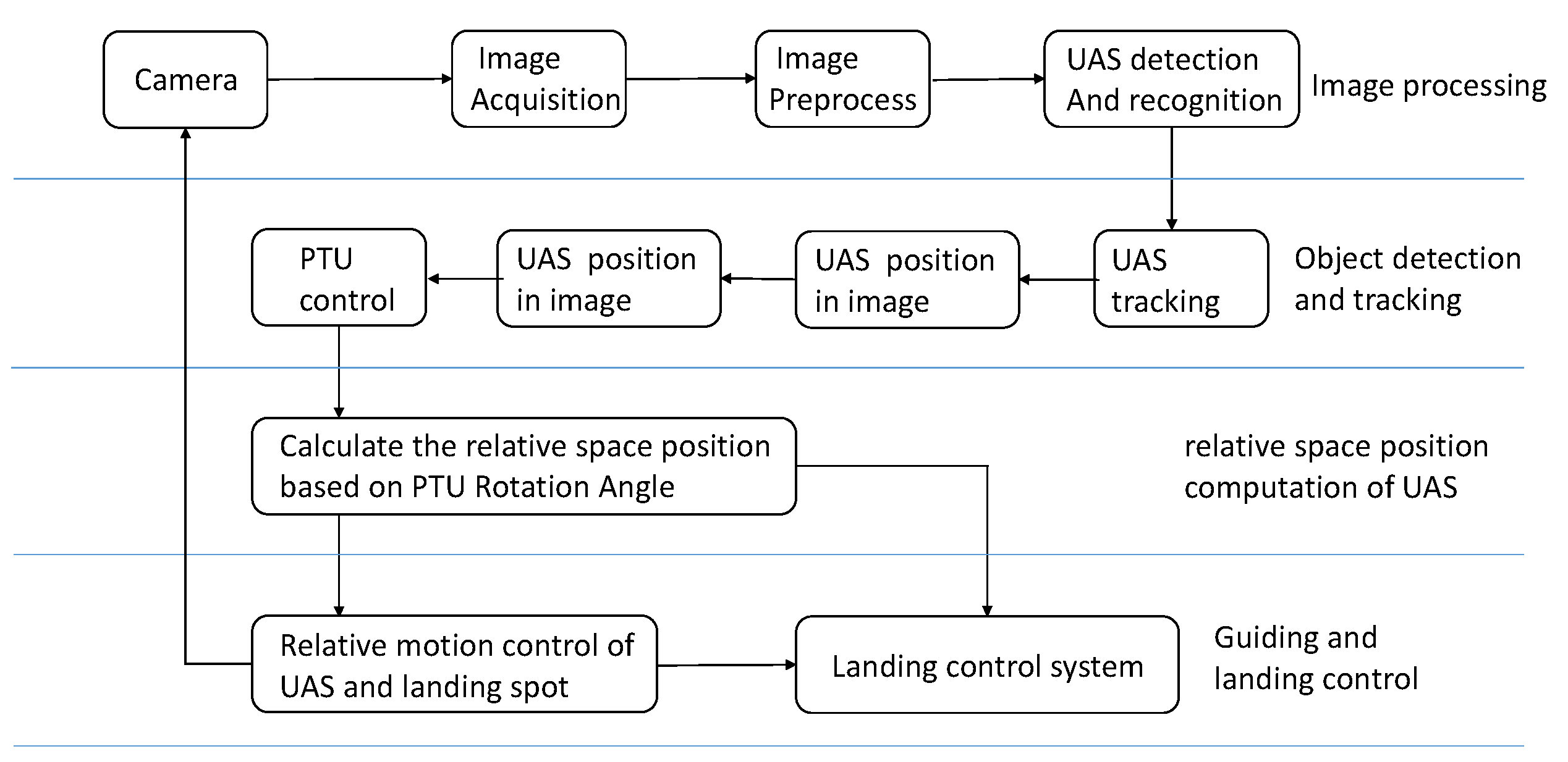
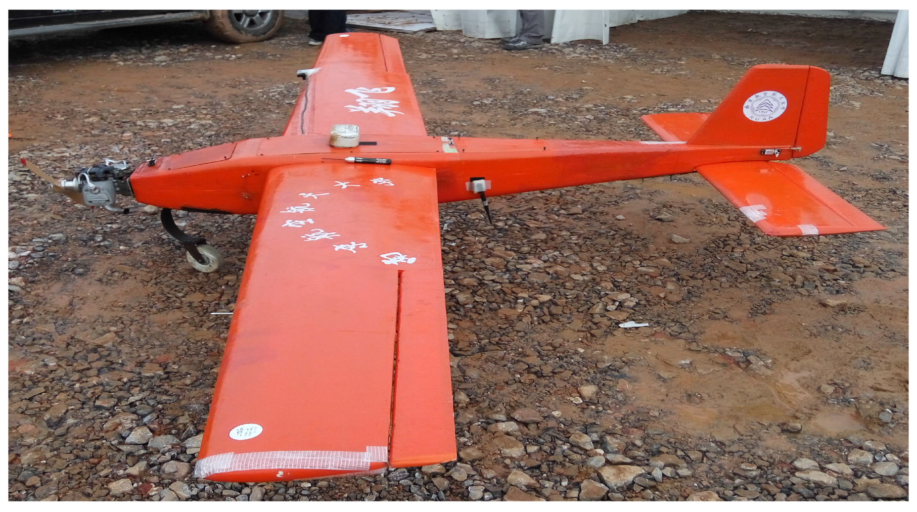
Figure 3.
UAS “xiangfei” platform.

Figure 4.
Fixed-wing UAS landing process.

Figure 5.
Frame difference flowchart.

Figure 6.
Region-Convolutional Neural Network (R-CNN) system overview.
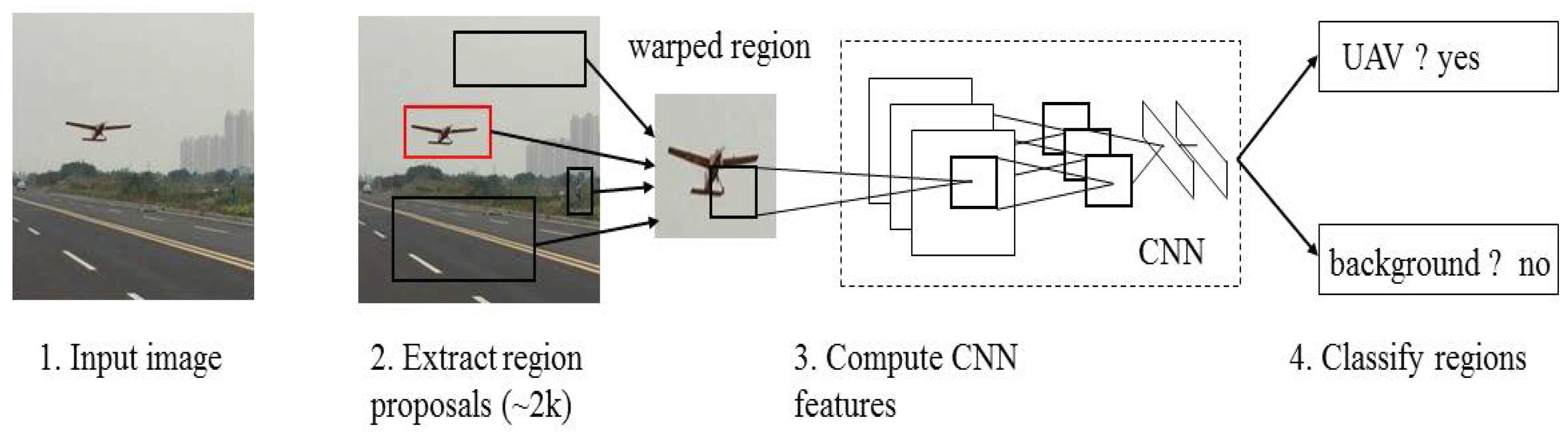
Figure 7.
Fast R-CNN system overview.

Figure 8.
Relationship among R-CNN, fast R-CNN, and faster R-CNN.

Figure 9.
Combination algorithm.
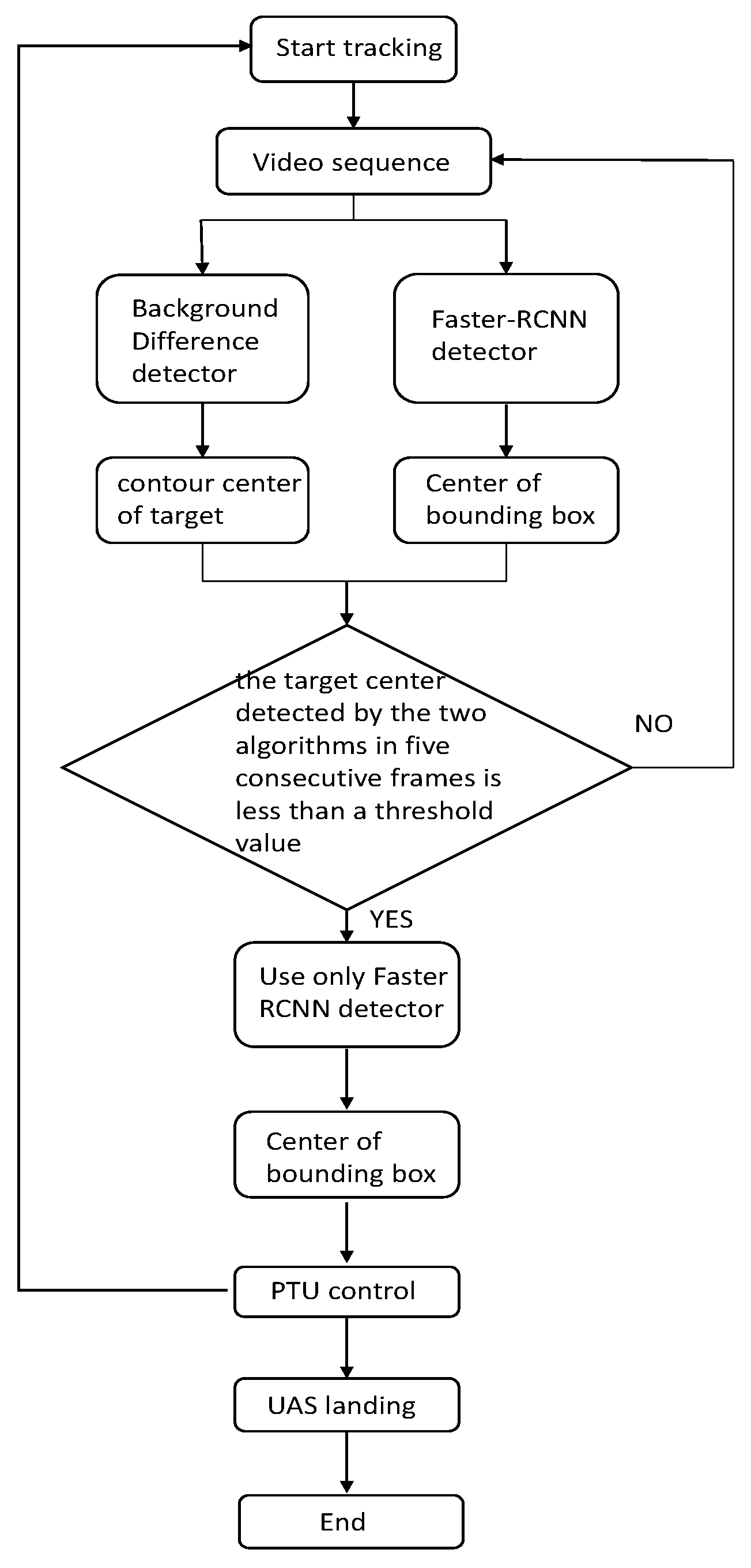
Figure 10.
Comparison of different CONF_THRESH values.
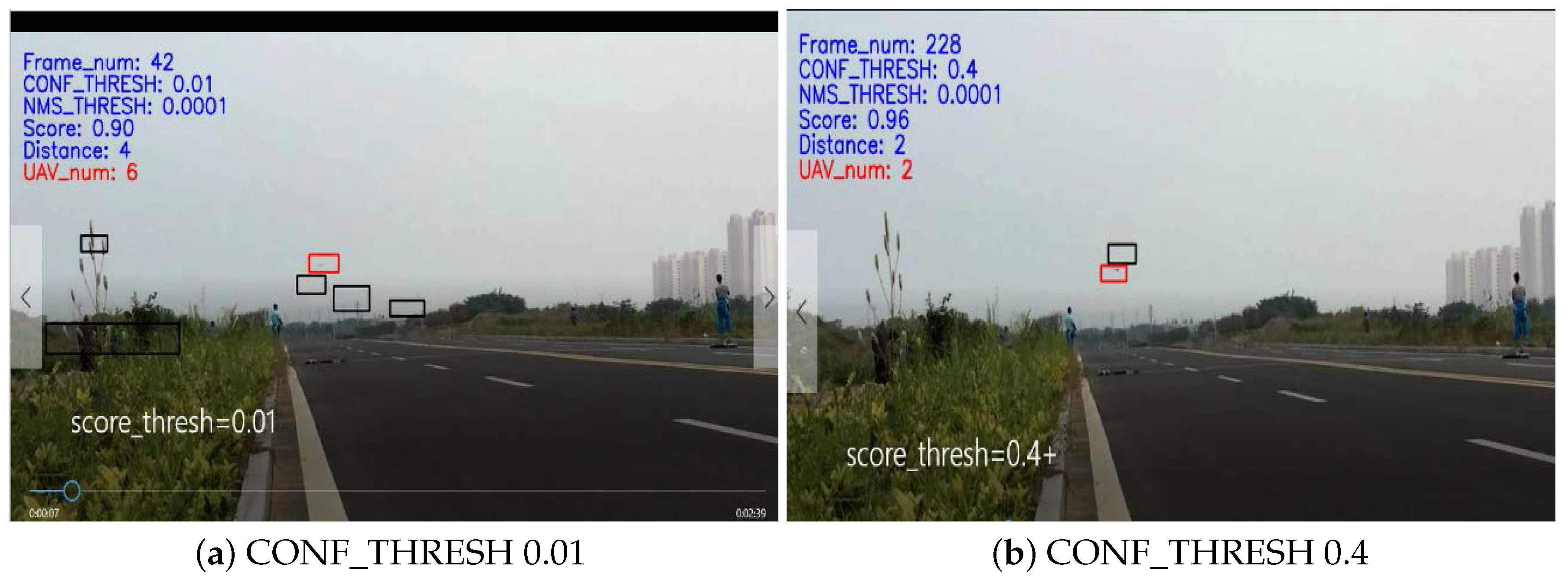
Figure 11.
Setting Region of Interest (ROI) based on motion smoothness.

Figure 12.
Images processed by the combined algorithm.

Figure 13.
Sketch of Intersection over Union (IoU).

Figure 14.
The recall rate under different CONF_THRESH value.

Figure 15.
The relationship between CONF_THRESH and IoU.
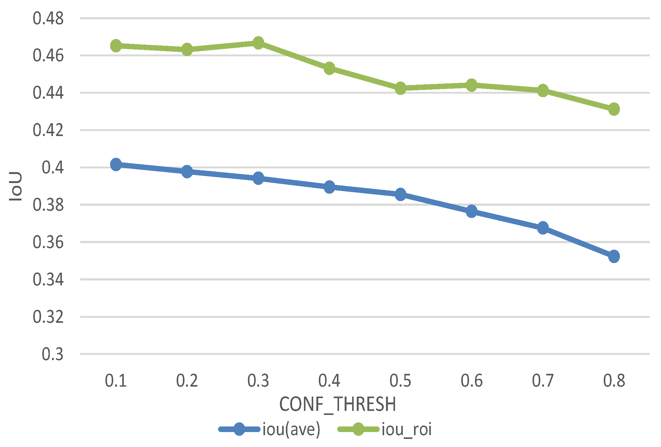
Figure 16.
The relationship between IoU and recall.
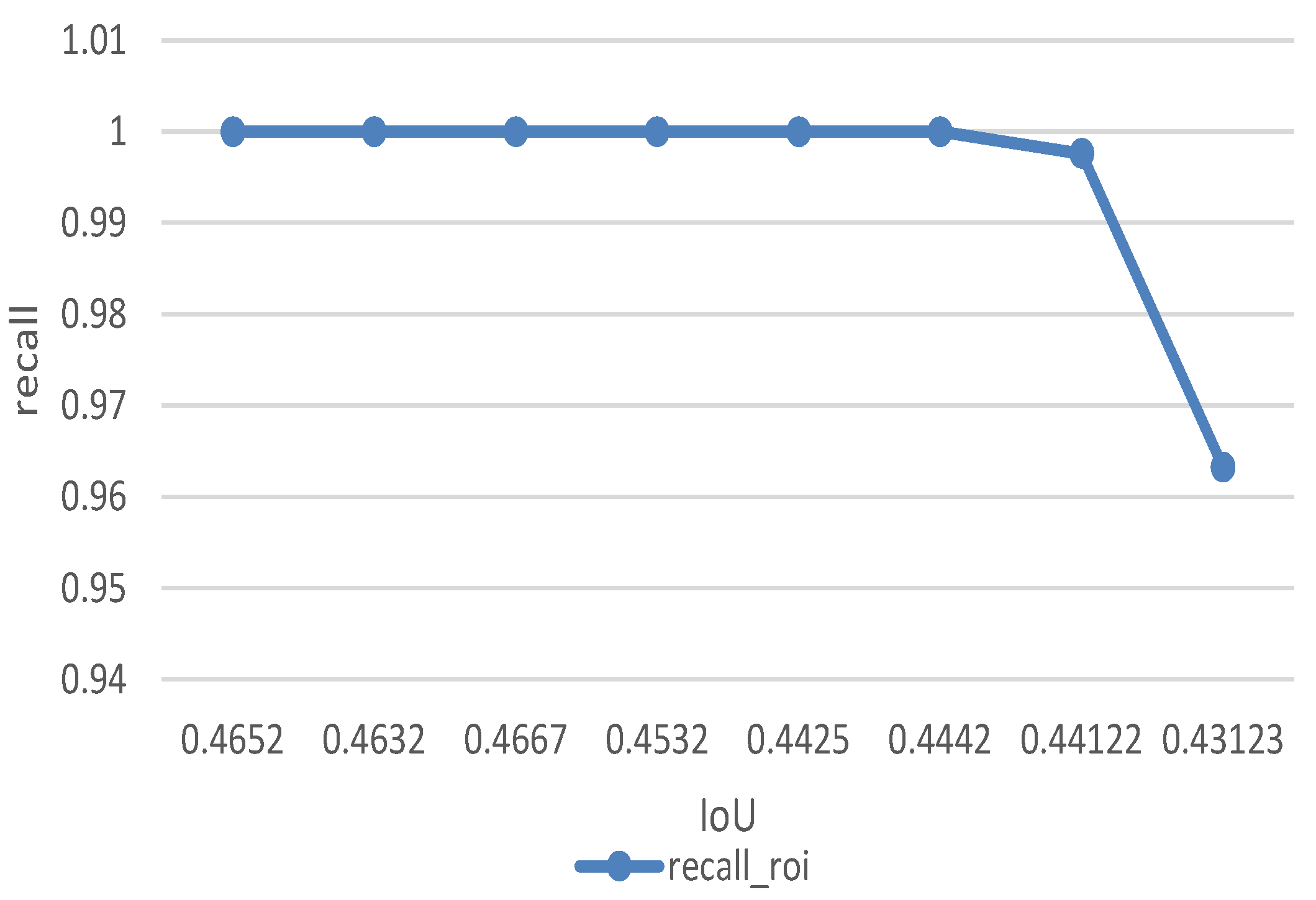
Figure 17.
Detection performance of Faster RCNN and Histogram of Oriented Gradient (HOG) + Support Vector Machine (SVM).
Figure 17.
Detection performance of Faster RCNN and Histogram of Oriented Gradient (HOG) + Support Vector Machine (SVM).


Table 1.
The technical specification of platform.
| Iterm | Description |
|---|---|
| Wingspan | 3.6 m |
| Flight duration | up to 120 min |
| Maximum payload mass | 8 kg |
| Cruising speed | 23.0 m/s |
Table 2.
Confusion Matrix.
| Actual Result | Prediction Result | |
|---|---|---|
| Positive | Negative | |
| Positive | TP (true positive) | FN (false negative) |
| Negative | FP (false positive) | TN (true negative) |
Table 3.
Real-time performance.
| Search Area | Whole Image | Whole Image | ROI |
|---|---|---|---|
| Number of proposals | 300 | 100 | 100 |
| Time per frame | 110–115 ms | 85–95 ms | 25–35 ms |
© 2017 by the authors. Licensee MDPI, Basel, Switzerland. This article is an open access article distributed under the terms and conditions of the Creative Commons Attribution (CC BY) license (http://creativecommons.org/licenses/by/4.0/).
Share and Cite
MDPI and ACS Style
Yang, Y.; Gong, H.; Wang, X.; Sun, P. Aerial Target Tracking Algorithm Based on Faster R-CNN Combined with Frame Differencing. Aerospace 2017, 4, 32. https://doi.org/10.3390/aerospace4020032
AMA Style
Yang Y, Gong H, Wang X, Sun P. Aerial Target Tracking Algorithm Based on Faster R-CNN Combined with Frame Differencing. Aerospace. 2017; 4(2):32. https://doi.org/10.3390/aerospace4020032
Chicago/Turabian StyleYang, Yurong, Huajun Gong, Xinhua Wang, and Peng Sun. 2017. "Aerial Target Tracking Algorithm Based on Faster R-CNN Combined with Frame Differencing" Aerospace 4, no. 2: 32. https://doi.org/10.3390/aerospace4020032
Note that from the first issue of 2016, this journal uses article numbers instead of page numbers. See further details here.