2. Symmetrical/Anti-Symmetrical DFCW Chips That Are Quasi-Orthogonal
Let and be constructed by using , for , and (where or ) as chips for the Golay complementary code pair {, } of length , respectively. and can be represented as shown in Equation (3).
If
and
, then
where
and
represent the sampled versions of
and
, respectively,
is the number of samples in
and
}.
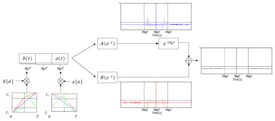
represents a code constructed by concatenating
and
with a gap
in between. At the receiver, this code is passed into two matched filters:
which is the matched filter of
, and
which is the MF of
. The cross-correlation of
with
results in,
where
represents the autocorrelation of
,
represents the chip ACF (
is the MF of
),
represents the cross-correlation of
with
and
represents the cross-correlation of
with
.
Similarly, the cross-correlation of
with
can be represented by,
where
represents the cross-correlation of
with
,
represents the ACF of
and
is the cross-correlation of
with
.
Delaying
by
and adding it to
results in,
Since
and
,
, Equation (17) becomes
contains the mainlobe () that is spread by the chip ACF (i.e., ), a zero-sidelobe region on either side of the mainlobe and an adjacent region of cross-correlation sidelobes (i.e., the first and the last terms in Equation (19)). If , then and represent symmetrical waveforms. If , then and represent anti-symmetrical waveforms. For both the symmetry () and anti-symmetry () conditions, ACF of , i.e., is identical to the ACF of , i.e., . As a result, exact sidelobe cancellation of the complementary code pair is achieved resulting in the zero-sidelobe region on either side of the mainlobe as shown in Equation (19). If and are also quasi-orthogonal in the convolution sense, i.e., their cross-correlation peak (as defined in Equation (10)) is small compared to the mainlobe peak (), then the first and the last terms in Equation (19) are small. It should be noted that using a sinusoidal chip for the complementary code pair will also result in a zero-sidelobe region around the mainlobe as it satisfies the symmetry/anti-symmetry condition. However, a sinusoidal chip is not quasi-orthogonal to its symmetrical/anti-symmetrical mirror image. Thus, the proposed codes with sinusoidal chip achieves zero-sidelobe region but the cross-correlation sidelobes outside the zero domain are large which is undesirable. Hence, any waveform that satisfies the two conditions, symmetry/anti-symmetry and quasi-orthogonality, could be used as chips for the complementary code pair in the proposed code design.
DFCWs based on LFM and PLFM waveforms are constructed by discretizing their instantaneous frequencies. These will be referred to as Discrete Frequency LFM (DF-LFM) and Discrete Frequency PLFM (DF-PLFM) waveforms, respectively. The DF-LFM and DF-PLFM waveforms satisfy the symmetry/anti-symmetry and the quasi-orthogonality conditions required for the chips in the proposed code design. The following three types of DFCWs are used as chips for the complementary code pair in the proposed code design:
Let
and
represent a DF-LFM/DF-PLFM waveform and its symmetrical mirror image respectively. The DF-LFM waveforms can be represented by,
where
,
,
,
and
. is the time-duration of the DFCW chip.
The DF-PLFM waveforms comprised of two up-chirp segments can be represented by,
where
for
,
and
for
.
The DF-PLFM waveforms comprised of an up-chirp and a down-chirp segment can be represented by,
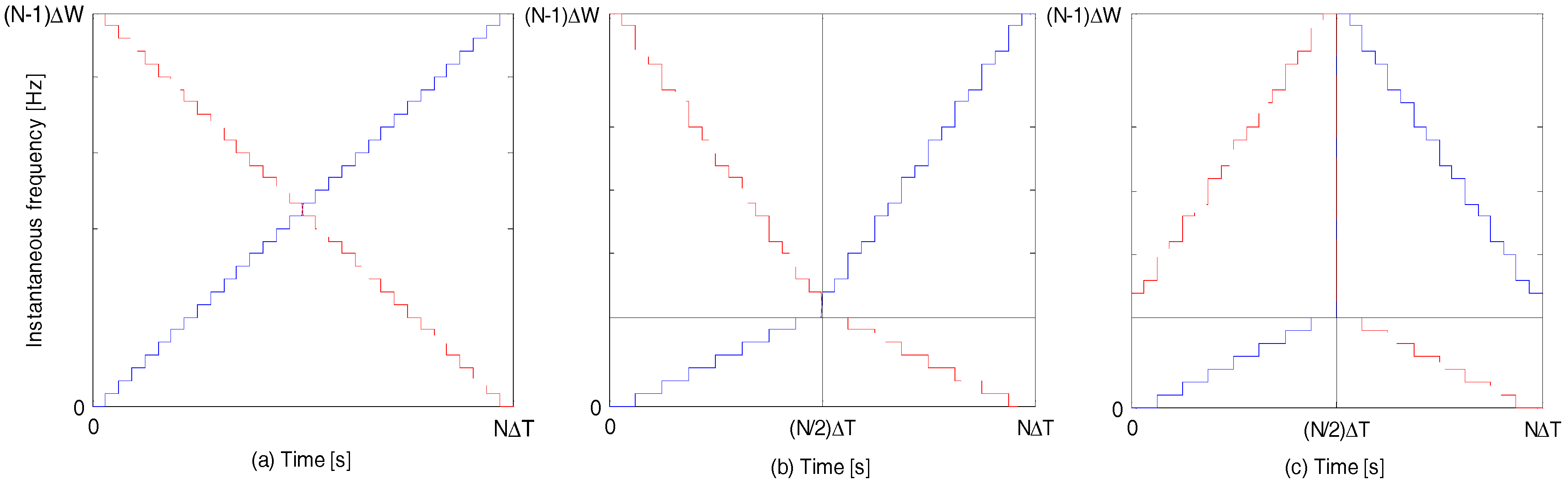
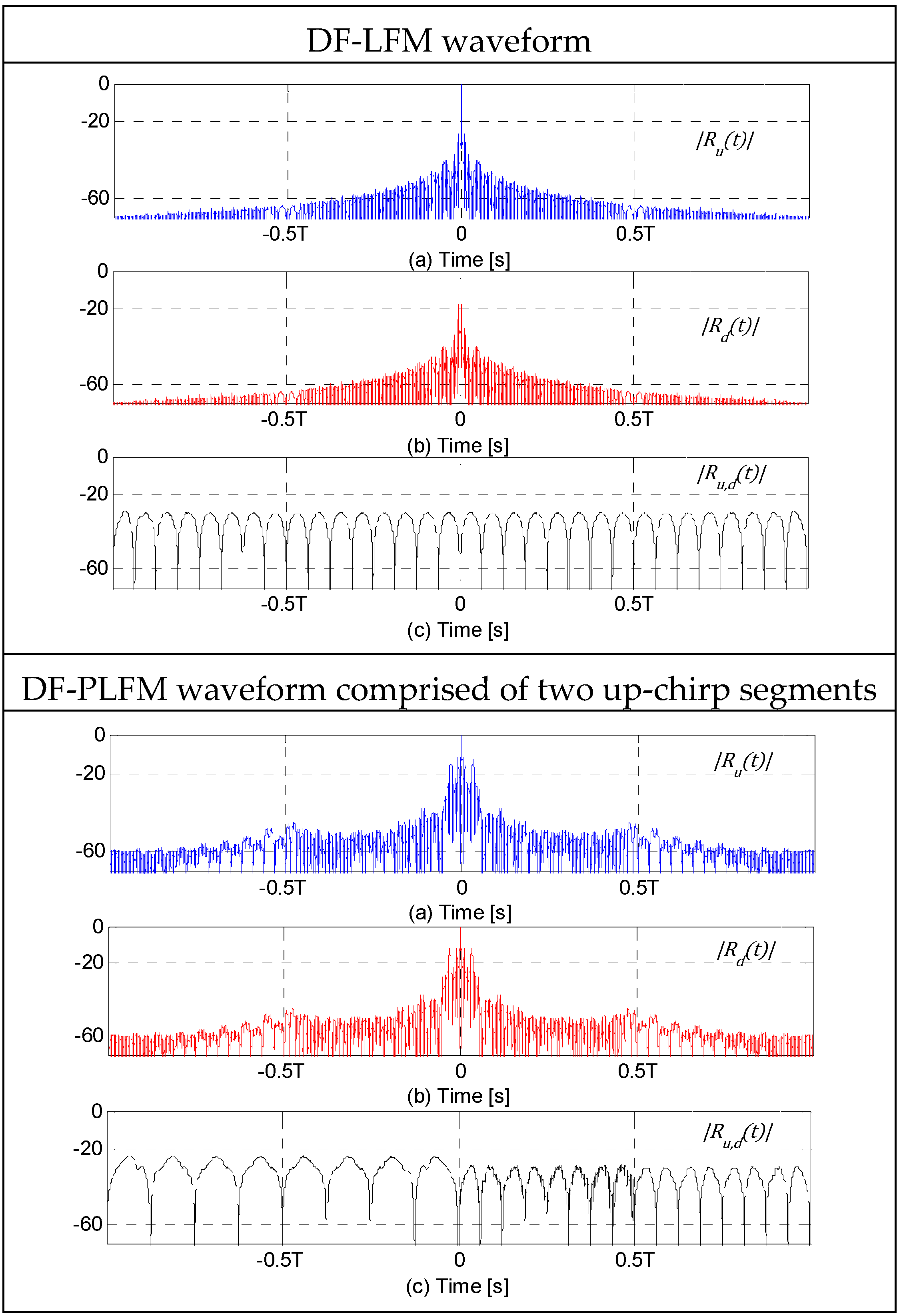
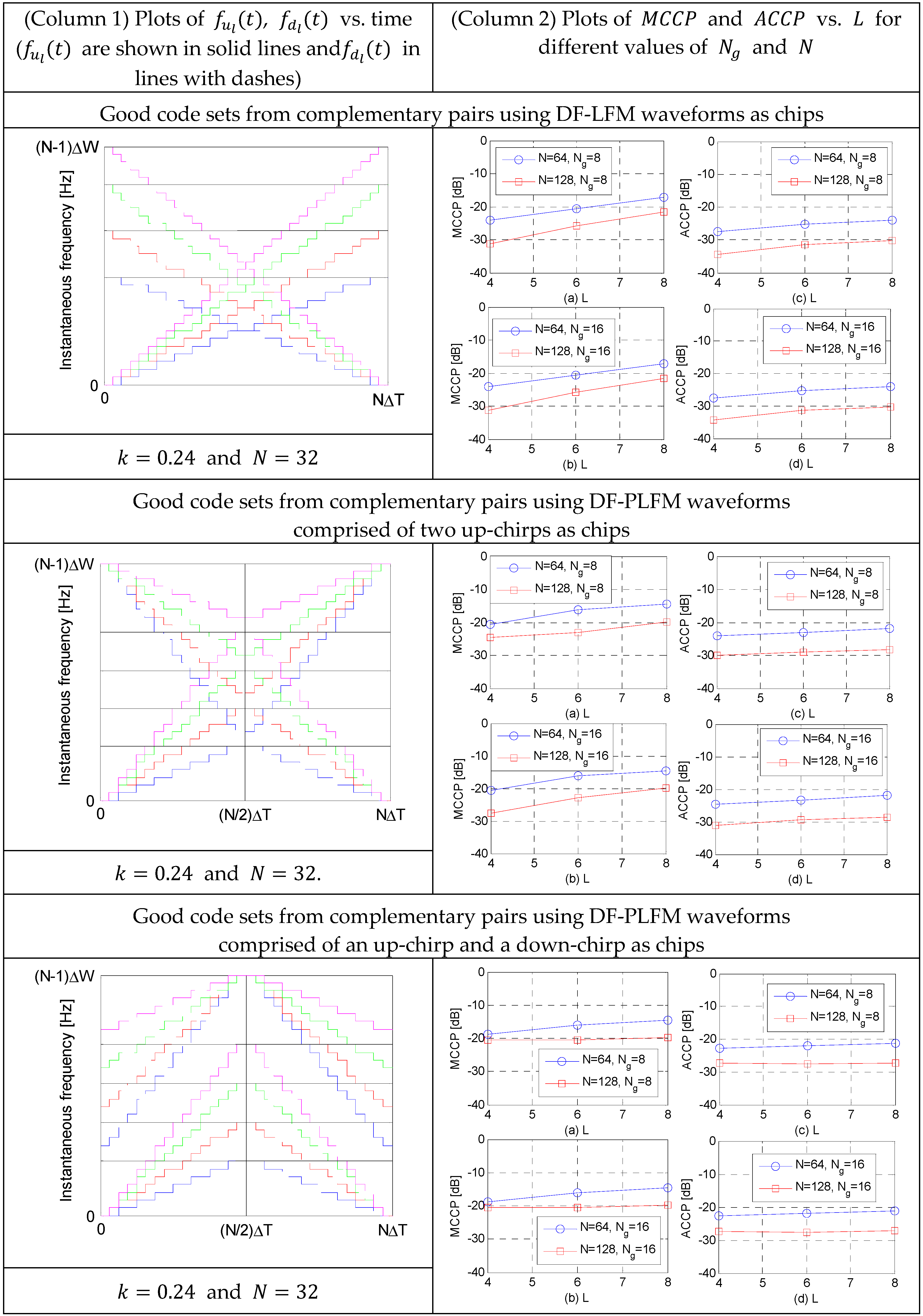
Figure 3 shows the plots of instantaneous frequencies of the aforementioned DFCW chips. Let
and
represent the instantaneous frequencies of
and
, respectively.
,
and
represent the ACF of
, ACF of
and cross-correlation between
and
respectively. They can be represented as shown in Equation (4). Since
and
are symmetrical mirror images of each other, their ACFs are identical, i.e.,
as shown in the plots in
Figure 4. Since
u(
t) and
are also quasi-orthogonal,
is very small as shown in their plots in
Figure 4. For these plots,
and
.
closes to
results in a DF-LFM/DF-PLFM waveform that is close to a pure sinusoid, while
close to
results in a very sharp slope.
3. The Proposed Code Based on Complementary Pair Using DF-LFM and DF-PLFM Waveforms as Chips
Let and represent a Golay complementary code pair of length . Let and represent the waveforms obtained by modulating (Equation (20), (22) or (24)) with and (Equation (21), (23) or (25)) with , respectively.
where
is the duration of
and
.
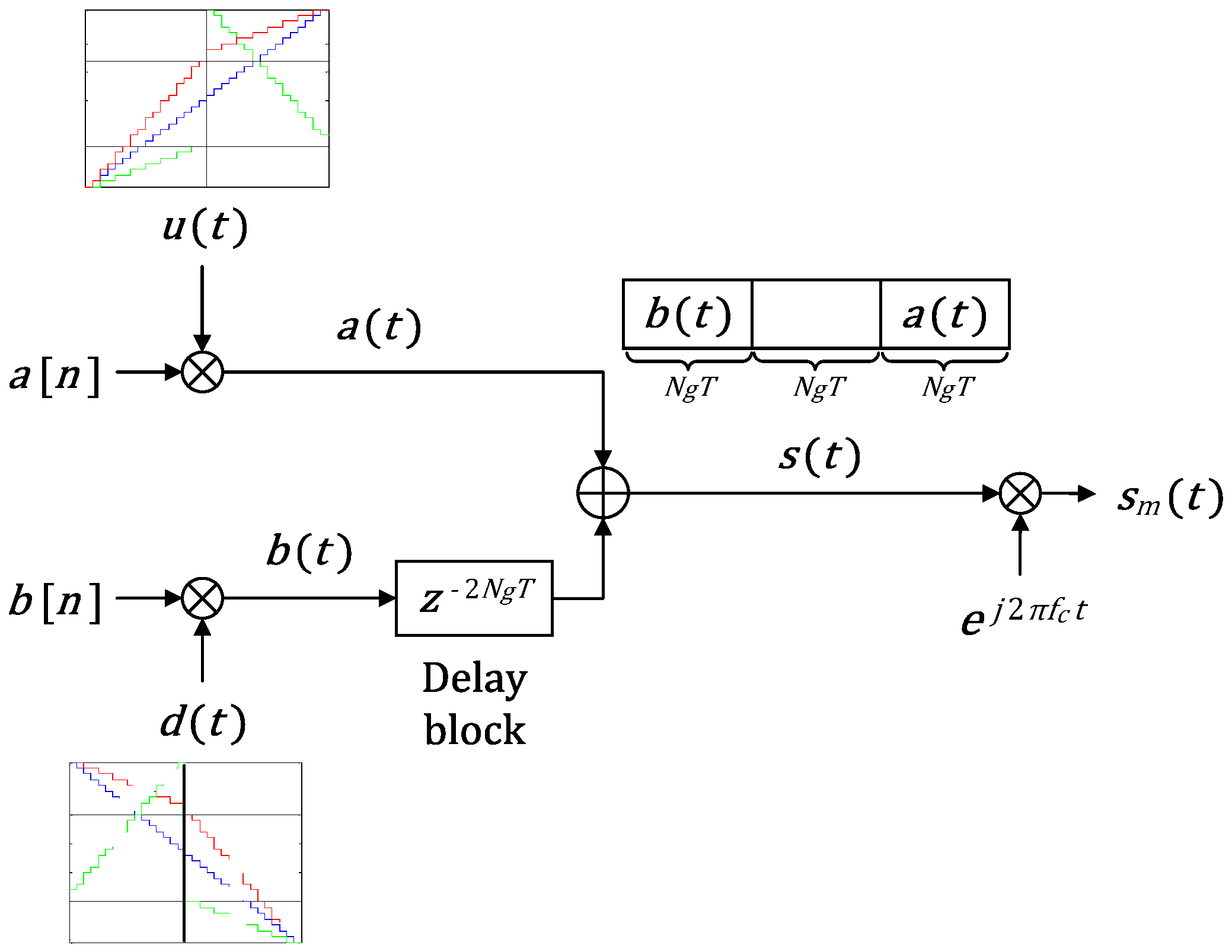
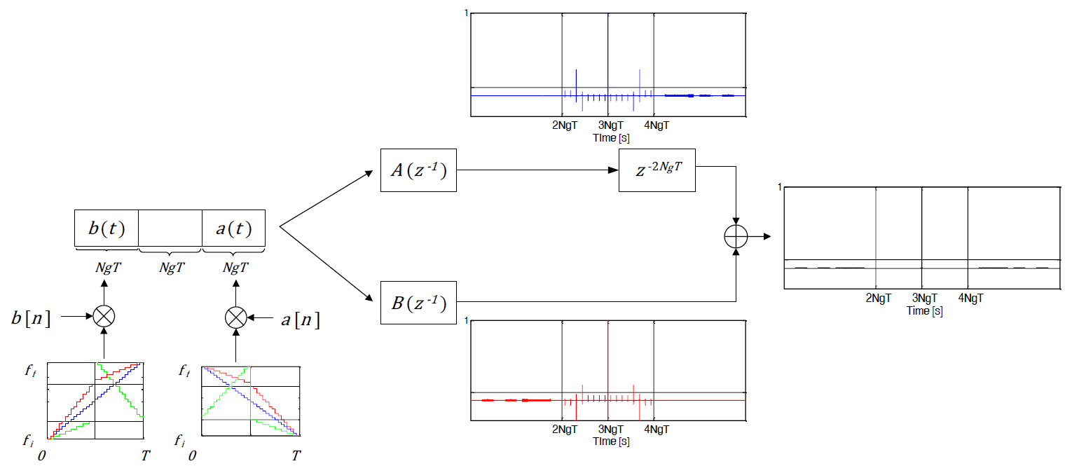
A new code,
, is constructed by concatenating
and
with a delay of
between them, as shown in
Figure 5.
is then carrier (
) modulated before transmission, resulting in
, as shown in
Figure 5. The transmitted signal can be represented by,
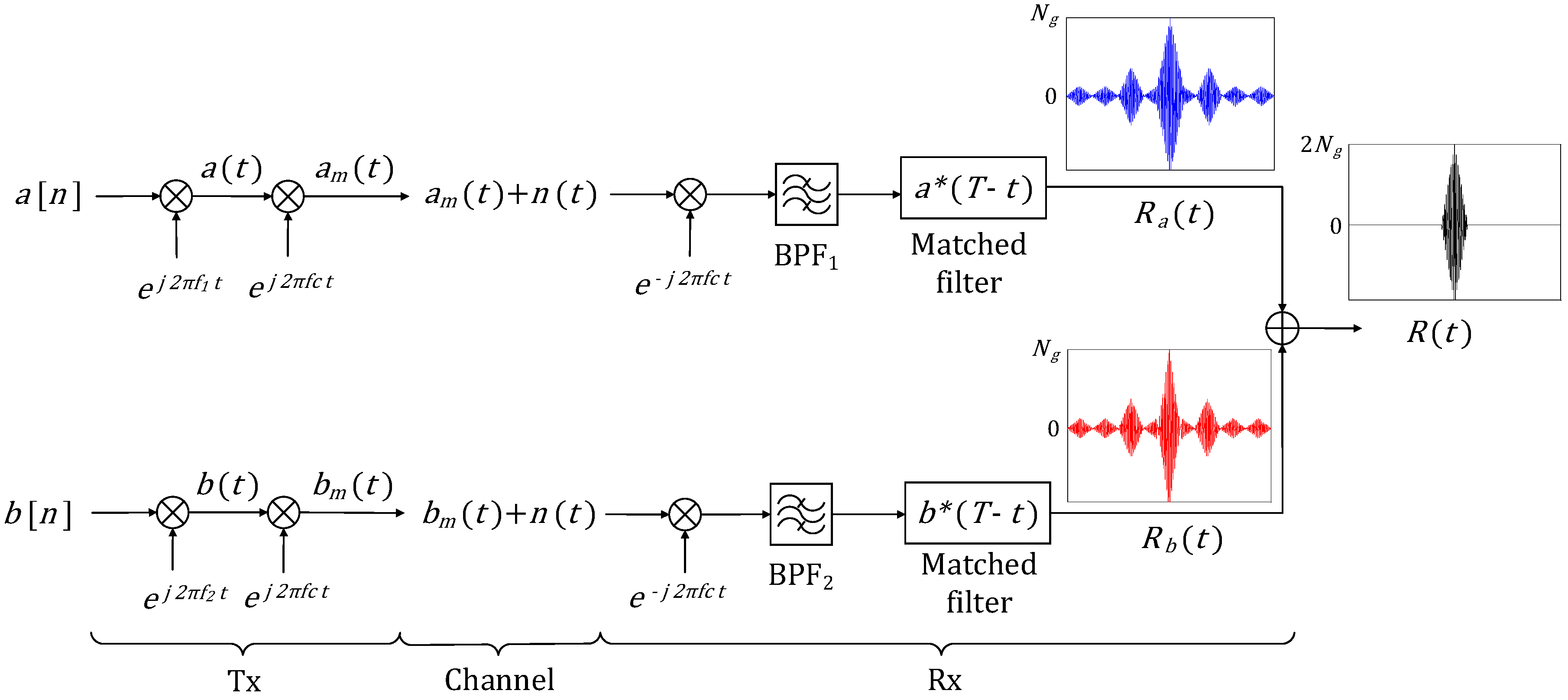
Figure 6 shows the block diagram of the receiver. The received signal,
, is first carrier demodulated and then bandpass filtered (BPF), giving
as shown in
Figure 6. Since both
and
occupy the same bandwidth, only one BPF is used.
represents additive white Gaussian noise.
In one path,
is passed into the matched filter (MF) of
implemented as a cascade of two MFs, one for the digital code (
) and the other for the chip (
), as shown in
Figure 6.
where
represents the ACF of
,
represents the cross-correlation of
with
and
represents the filtered noise process,
.
In another path, is passed into the MF of which is also implemented as a cascade of MF of and that of .
where
represents the cross-correlation of
with
, which can be represented as shown in Equation (17),
represents the ACF of
and
represents the filtered noise process,
.
Delaying
by
(as shown in
Figure 6) and adding it to
results in,
Since,
where
represents the ACF of the DFCW chip.
Thus, the final output,
, (excluding the noise terms) consists of,
In Equation (37),
is the mainlobe of
(
is the ACF of the DFCW chip, as shown in the plots in
Figure 4).
and
are the zero-sidelobe regions on either side of the mainlobe.
and
(defined in Equation (32)), respectively, represent the small cross-correlation sidelobes. Let
represent the peak cross-correlation sidelobe. Since,
and
are mirror images of each other,
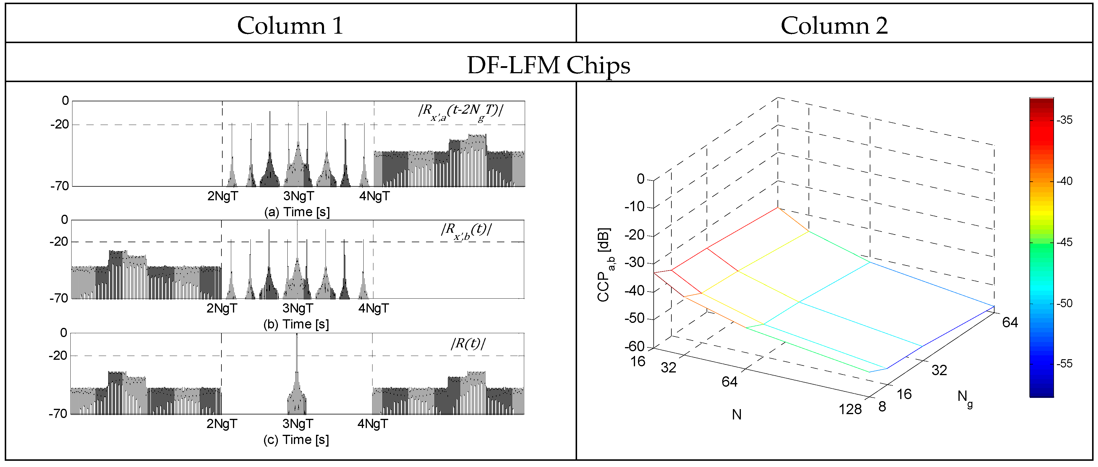
The table in
Figure 7 shows the plots of
,
and
, all normalized by
and in the absence of noise, for
and
for the three DFCW chips in Column 1. 3D-plots of the corresponding cross-correlation peaks (
) for a range of
and
are shown in Column 2. Clearly, the ACF plots show the zero-sidelobe region around the mainlobe and the adjacent region of small cross-correlation sidelobes. From the 3D-plots of
it can be observed that
values are very small, and decrease in magnitude as the code length
and the number of discrete frequencies
in the DF-LFM/DF-PLFM chips increase. In addition, the
values are slightly larger for the codes constructed using the DFCW chips based on PLFM waveforms compared to the
values for the codes constructed using DFCW chips based on LFM waveform, but still very small (
).
If
and
are concatenated and transmitted at a second frequency band and received using a receiver similar to the one described in
Figure 6, then the final output of this code can be represented by,
Clearly, adding Equations (37) and (39) results in complete cancellation of the cross-correlation sidelobes. Thus, achieving complete zero-sidelobes on either side of the mainlobe. This is shown in the plots of
,
and
for
and
in
Figure 8. Frequency selective fading between the two bands could result in inexact cancellation of the cross-correlation sidelobes that are adjacent to the zero-sidelobe region. However, since the cross-correlation sidelobes are very small, any inexact cancellation due to fading will not create undesirable high magnitude sidelobes.
The complementary code pair could also be interlaced in the time domain (i.e.,
). This scheme results in a transmission without gaps, while still using the same frequency band as in the previous scheme. Fishler et al. [
18] and Deng [
19] describe this scheme using continuous LFM and PLFM chips. However, for this interlaced code, the zero-sidelobes and the small cross-correlation sidelobes in the final output are interlaced as well.
5. Effect of Frequency Selective Fading
In the presence of frequency selective fading, the higher frequencies within the frequency sweep () of the DF-LFM/DF-PLFM waveforms could be slightly attenuated compared to the lower frequencies. However, autocorrelations of the DF-LFM/DF-PLFM waveforms remain identical, since they are symmetrical. Hence, the zero-sidelobe region is not affected. However, the adjacent region of small cross-correlation sidelobes could vary slightly depending on the attenuation due to fading. However, its effect on the error in the location of the mainlobe is negligible as will be shown in the simulation results later in this section.
In the presence of frequency selective fading, let the lower and the higher frequency components of the DF-LFM/DF-PLFM chips be attenuated by
and
respectively, where
. The DF-LFM chips (
and
) in the presence of fading can be represented by,
The DF-PLFM chips comprised of two up-chirp segments in the presence of fading can be represented by,
The DF-PLFM chips comprised of an up-chirp and a down-chirp segment in the presence of fading can be represented by,
For the DF-LFM waveforms, all the discrete frequencies
, are considered as the lower frequency component which are attenuated by
, while the discrete frequencies
will be considered as the higher frequency component which are attenuated by
. For the DF-PLFM waveforms, all the discrete frequencies
are considered as the lower frequency component and
, the higher frequency component.
Figure 10 shows the autocorrelations of the DF-LFM chips with and without fading, i.e.,
and
and
and
for
,
,
,
and
(
and
are randomly generated). Although, fading results in reducing the mainlobe peaks of the autocorrelations,
and
(as seen in the plots), they remain identical.
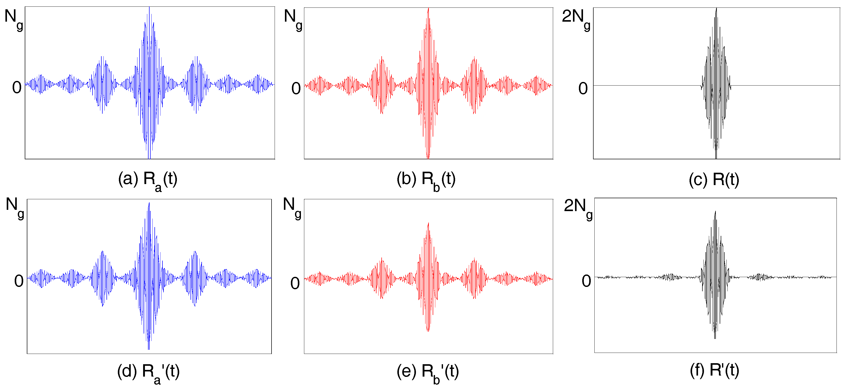
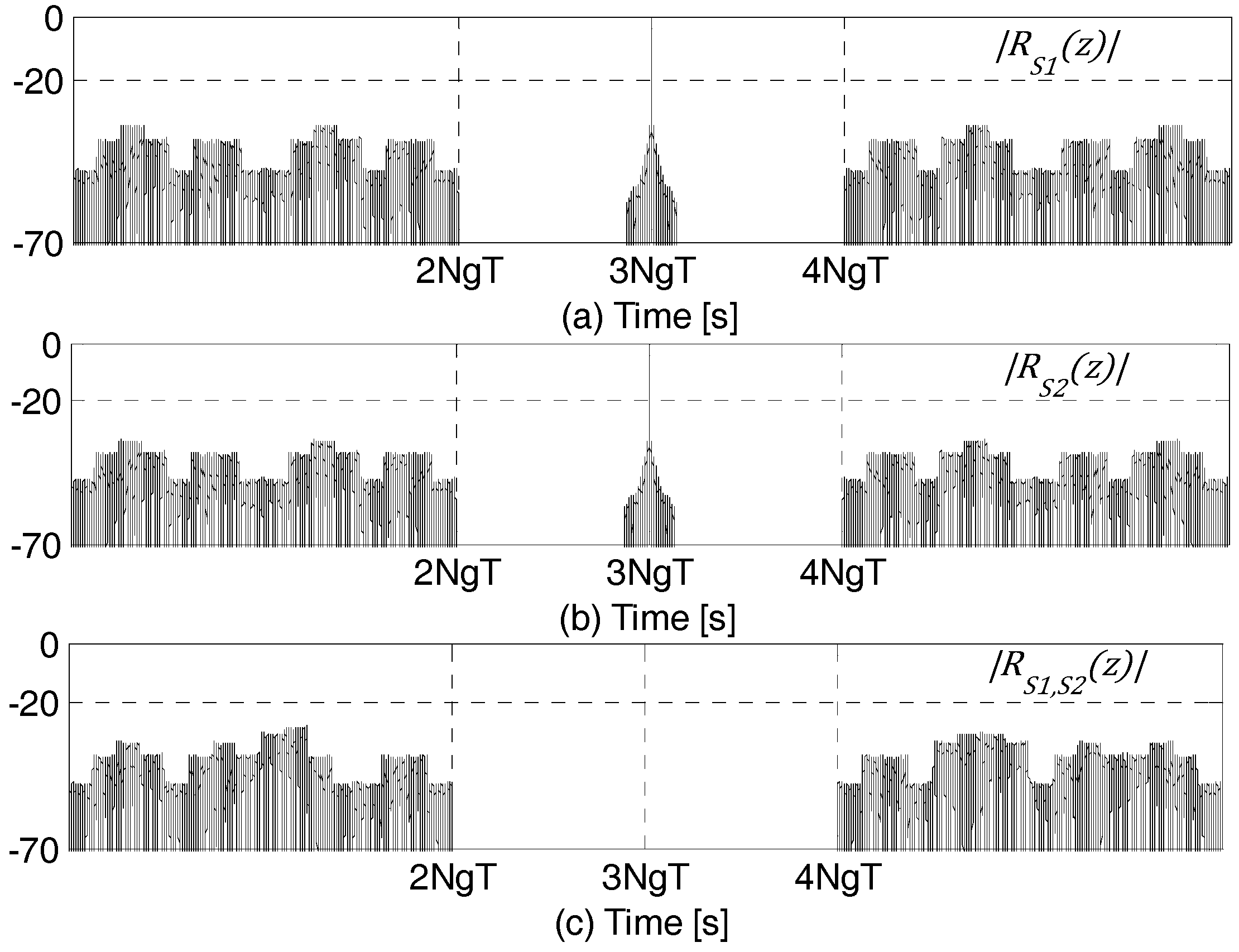
Figure 11 shows the matched filter outputs,
and
, and their sum
(given by Equations (30), (33) and (37), respectively), in the presence of frequency selective fading. Clearly, the zero-sidelobe region on either side of the mainlobe is not affected by fading.
Root mean square error (
) in the location of the mainlobe is used as a metric to measure of effectiveness in sidelobe cancellation in the presence of frequency selective fading and noise. Location of the mainlobe of
is given by,
where
is the final output, given by Equation (37).
in the location of the mainlobe can be represented by,
where
is the number of trials,
is the actual timing of the mainlobe,
is the estimated timing of the mainlobe for the
ith trial in the presence of noise and
is the chip duration.
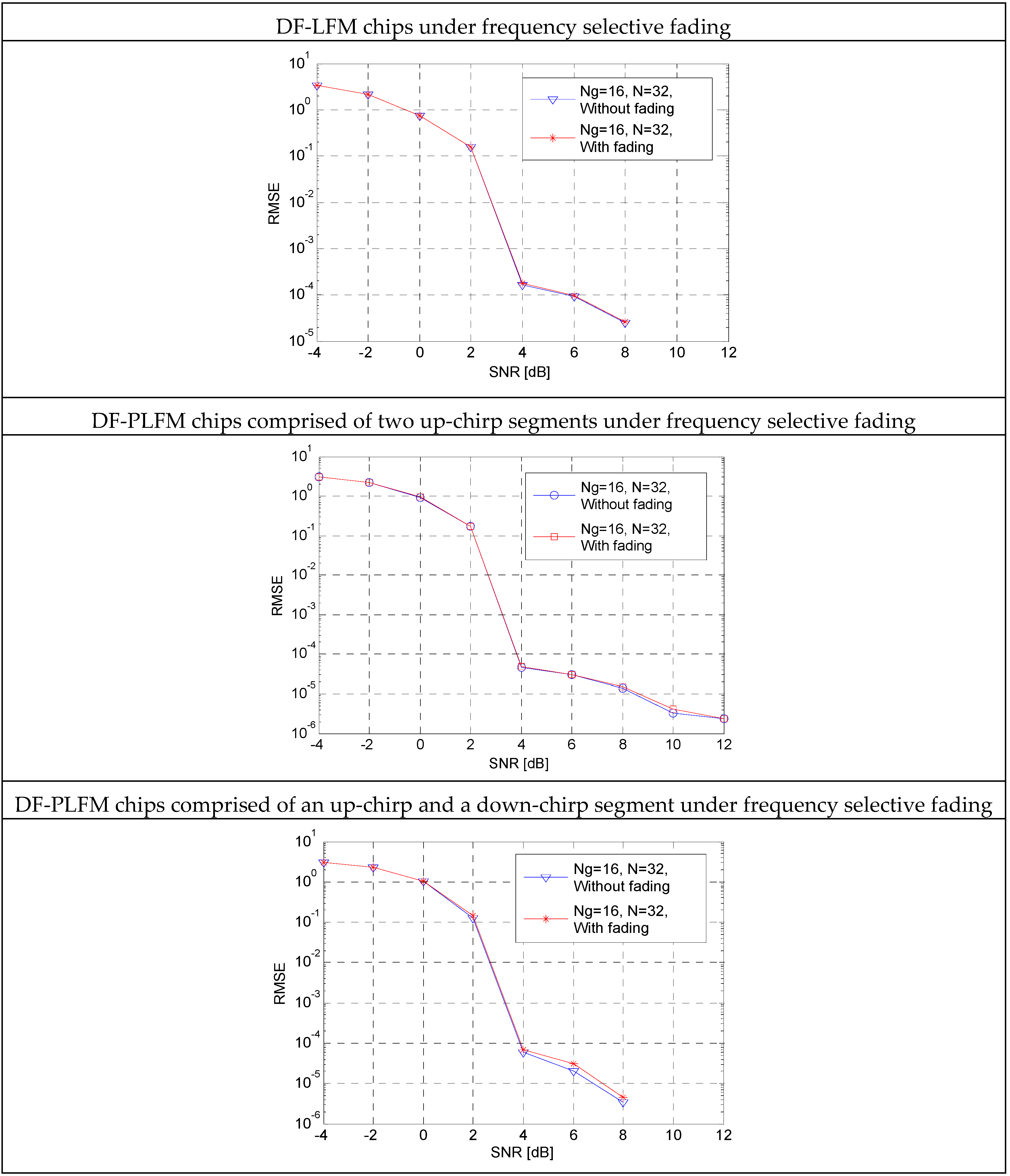
vs. signal-to-noise ratio (SNR) plots for the proposed codes are shown in
Figure 12.
SNR is given by , where is the code energy and represents the noise power. SNR is varied by changing and iterations are performed for each SNR value. and are randomly chosen such that . From these plots it can be observed that the curve with fading stays very close to the in the absence of fading. This is true for the DF-LFM and the DF-PLFM chips.
As discussed in the Introduction, complete sidelobe cancellation can be achieved using a complementary code pair. However, it requires transmission and reception of the complementary code pair at two frequencies/channels as shown in
Figure 1. In the presence of frequency selective fading, the cancellation of sidelobes is inexact which results in increasing the probability of false alarm. This can be seen in the plots of
vs. SNR in
Figure 13 for a Golay complementary code pair (
) of length
and 64.
is attenuated by
and
is attenuated by
such that
. It can be observed that frequency selective fading results in increasing the RMSE in the location of the mainlobe. The proposed codes are resistant to the effect of frequency selective fading, as shown in the
plots in
Figure 12.
6. Good Code Sets from Complementary Pair Using DF-LFM and DF-PLFM Waveforms as Chips
A good code set is constructed by changing the slopes of the instantaneous frequency (shown in the plots in
Figure 3) of the DF-LFM/DF-PLFM waveforms used as chips for the same complementary code pair. The parameter
, as shown in the Equations (20)–(25), is varied carefully to result in DF-LFM and DF-PLFM chips with different slopes. The resulting good code set has a zero domain on either side of the mainlobe and an adjacent region of small sidelobes. The cross-correlation between any code pair in the set is very small. The
lth code in the set can be represented by,
where
,
, and
and
represent the two symmetrical DF-LFM/DF-PLFM waveforms.
and
for the good code sets from complementary pairs using DF-LFM chips can be represented by,
where
for
,
,
,
,
and
.
and
for the good code sets from complementary pairs using DF-PLFM chips comprised of two up-chirps can be represented by,
where
for
,
,
for
and
.
and
for the good code sets from complementary pairs using DF-PLFM chips comprised of an up-chirp and a down-chirp are given by,
The receiver for each code is as shown in
Figure 6. The ACFs of all the codes in the set are as shown in the plots in
Figure 7. Thus, the autocorrelation sidelobe peak (
) of the
code in the set is given by,
where
is the same as
which is defined in Equation (38) and shown in the plots in
Figure 7.
Maximum cross-correlation peak () and average cross-correlation peak () are used as measures to compare the different good code sets introduced in this paper.
where
is the normalized cross-correlation between the code pair {
} in the set.
The table (Column 2) in
Figure 14 shows the plots of
and
for each set for different values of
,
and
.
From the plots in
Figure 14, it can be observed that the good code sets constructed using DF-LFM chips have better
and
properties compared to those constructed using DF-PLFM chips. However, the time bandwidth products of all the codes in the sets constructed using DF-PLFM chips is the same (i.e.,
), while those of the codes in the set constructed using DF-LFM chips are different. In addition, for a given complementary code pair code length (
), the cross-correlation sidelobe peaks could be reduced by increasing the number of discrete frequencies (
) in the chips.
7. Construction of a Good Code Set from the Mates of a Complementary Code Pair
Consider the complementary code pair:
and
. The sum of the cross-correlation of
with
and that of
with
will be,
Thus, the code pair:
and
, are orthogonal to the complementary code pair:
and
. Such code pairs are called complementary code pair mates, as described in [
23,
24].
Let
and
be the codes constructed by concatenating the complementary code pair mates (
,
and
,
) using
and its symmetrical/anti-symmetrical mirror image (
, where
) as chips, as described in
Section 2. Their autocorrelations can be represented by,
Both the autocorrelations consist of a zero-sidelobe region on either side of the mainlobe and an adjacent region of small cross-correlation sidelobes, as shown in Equation (37) in
Section 2. Their autocorrelation sidelobe peaks (i.e.,
, given by (38)) vary with
and
as shown in the plots in
Figure 7. The cross-correlation between
and
can be represented by,
Simplifying Equation (62) results in,
Clearly, the cross-correlation consists of a zero-sidelobe region and an adjacent region of small cross-correlation sidelobes. Thus,
and
are quazi-orthogonal in the convolution sense. The zero-sidelobe domain in the cross-correlation is due to the symmetry/anti-symmetry property of the chips. Since, the symmetry/anti-symmetry property is immune to frequency selective fading, the zero-sidelobe domain in the cross-correlation is also immune to frequency selective fading.
Figure 15 show the autocorrelations
and
and their cross-correlation. For these plots,
and
are constructed using DF-LFM chips with
and
. These plots clearly show the zero-sidelobe domain in the cross-correlation between the proposed code constructed using a complementary code pair and the one constructed using its mate.
Varying the slopes of the DFCW chips in both
and
, as shown in
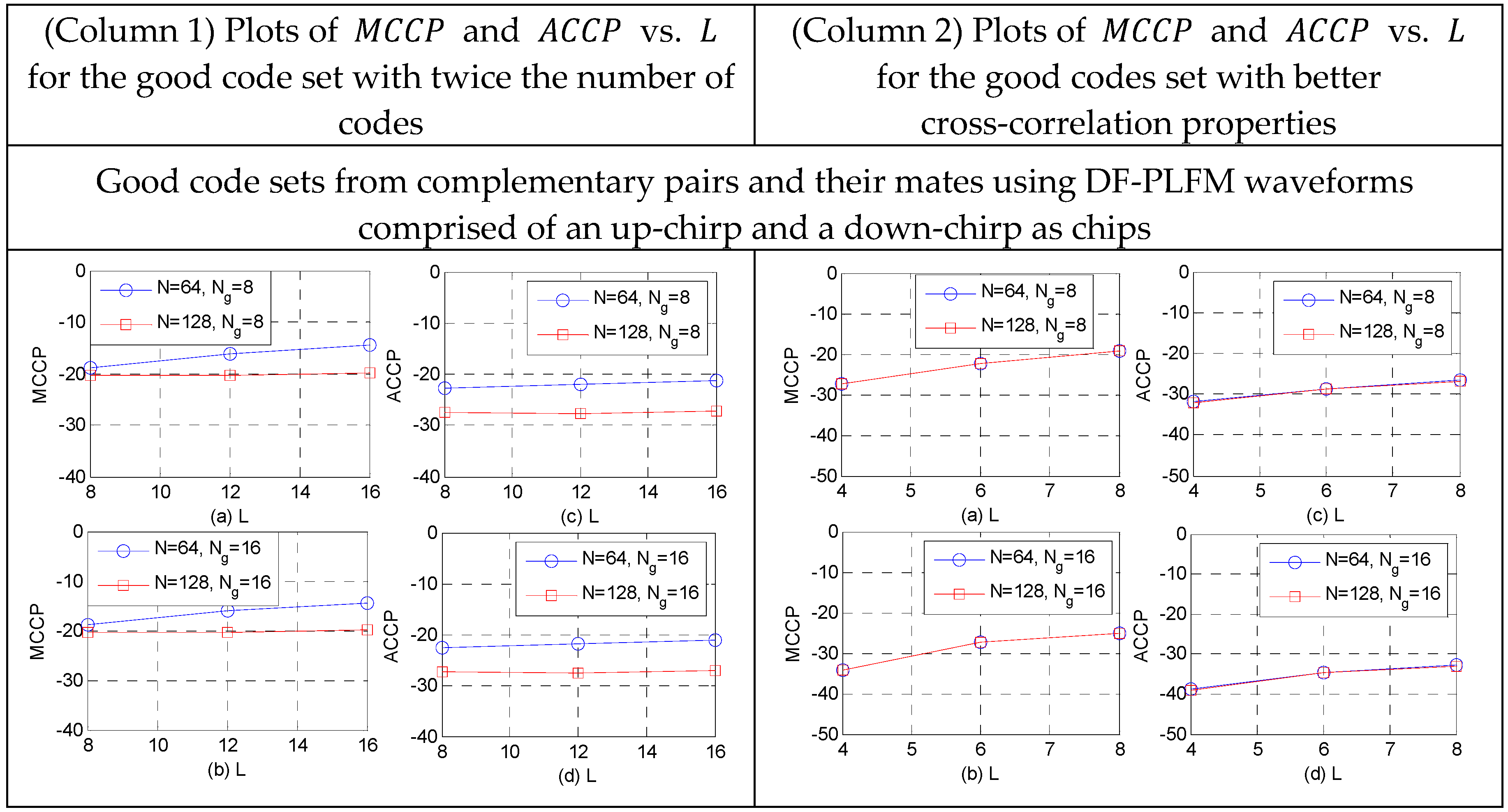
Section 6, results in two good code sets. Since these two sets are quasi-orthogonal to each other, they could be combined to form a larger set with twice the number of codes, while maintaining the same cross-correlation properties as those of the individual sets. This can be seen in the plots of maximum cross-correlation peaks (
) and average cross-correlation peaks (
) in Column 1 of the table in
Figure 16 and
Figure 17. When compared to the plots in
Figure 14, clearly the cross-correlation properties remain the same, while doubling the number of the codes in the set.
If a better good code set with the smaller
and
is required, then the best candidates from the two sets could be selected. This could be achieved by using only half the slope options for the DFCW waveforms used as chips for the complementary code pair and its mates i.e., the DF-LFM/DF-PLFM waveforms with
in Equations (52)–(57). This results in a good code set with significantly better
and
values, as shown in the plots in column 2 of the table in
Figure 16 and
Figure 17. These are significantly smaller than the
and the
values in
Figure 14 for the same number of codes in the set. Thus, constructing the proposed codes from complementary code pair and their mates, while using the same chips for both pairs, offers the aforementioned flexibility of choosing between a better good code set and a larger good code set.
Table 1 shows the average autocorrelation and average cross-correlation values for the Deng’s polyphase [
28] good code set and the Deng’s discrete frequency [
20] set designs. The autocorrelation and cross-correlation sidelobe peaks of the codes introduced in this paper are smaller, as shown in the plots in
Figure 7 and
Figure 17 respectively. The proposed codes constructed via concatenating biphase Golay complementary code pairs and using discrete frequency chips results in a zero-sidelobe domain and an adjacent region of very small cross-correlation sidelobes. In [
28], it is shown that the average autocorrelation sidelobe and cross-correlation peaks decrease with increase in code length and approach
for large
. Their discrete frequency good code set [
20] being wideband, achieve much smaller sidelobe peaks. In the case of the good code set design proposed in this paper, for a given code length (
), increasing the number of discrete frequencies (
) in the chips results in a better code set.
8. Conclusions
In this paper, it is shown that, by replacing the sinusoidal chips in the complementary code pair with waveforms that satisfy two conditions, symmetry/anti-symmetry and quazi-orthogonality in the convolution sense, allows for concatenating them in the time domain using one frequency band/channel. This results in a zero sidelobe domain around the mainlobe and an adjacent region of small cross-correlation sidelobes. Symmetry/anti-symmetry property results in the zero-sidelobe region, while the quasi-orthogonality property makes the adjacent region of cross-correlation sidelobes small. Discrete frequency coding waveform (DFCW) based on LFM and PLFM waveforms are used as chips, since they satisfy both the symmetry/anti-symmetry and quasi-orthogonality conditions. Since, frequency selective fading does not affect the symmetry/anti-symmetry property, the zero-sidelobe region is resistant to the effects of fading. A good code set with a zero-sidelobe region is then constructed by varying the slopes of the DFCW chips, while using the same complementary code pair. Such good code sets are constructed using a set of quasi-orthogonal DFCW chips based on LFM and PLFM waveforms. It is also shown that mates of the complementary code pair could be used to generate a second good code set using the same DFCW chips. These two sets are shown to be quasi-orthogonal with a zero-sidelobe domain. Thus, resulting in a larger good code set with twice the number of codes, while maintaining the same cross-correlation properties. Or a better good code set could be constructed by choosing the best candidates from the two sets.
As a topic for further research, the proposed codes could be constructed using polyphase versions (as shown in [
29,
30]) of the LFM/PLFM waveforms as chips with the complementary code pairs and their mates. Exploring other waveforms or codes that satisfy the two conditions of symmetry/anti-symmetry and quazi-orthogonality and improving the Doppler properties of these codes are the other topics of future research.


