
The Reliability Modeling and Evaluation of a Cusped Field Thruster When Undertaking a Gravitational Wave Detection Mission

1
School of Aeronautics and Astronautics, Sun Yat-sen University, Shenzhen 518107, China
2
School of Advanced Manufacturing, Sun Yat-sen University, Shenzhen 518107, China
3
Shenzhen Key Laboratory of Intelligent Microsatellite Constellation, School of Aeronautics and Astronautics, Sun Yat-sen University, Shenzhen 518107, China
*
Author to whom correspondence should be addressed.
Aerospace 2024, 11(5), 329; https://doi.org/10.3390/aerospace11050329
Submission received: 25 February 2024
/
Revised: 8 April 2024
/
Accepted: 16 April 2024
/
Published: 23 April 2024
(This article belongs to the Special Issue Space Electric Propulsion Technology)
Abstract
:The propulsion system, particularly electric propulsion, holds immense significance in the context of gravitational wave detection missions. One of the key factors of a deep space exploration mission is the lifetime of the electric propulsion. Ensuring the high reliability of the propulsion system is of paramount importance; however, achieving this is challenging in the absence of adequate failure data. Conducting ground tests for a thruster tends to encounter two limitations: a lack of failure data and time constraints. To address these challenges, we propose a semi-physics sputtering method that combines a physical erosion model with empirical processes. In this study, we focus on evaluating the lifespan of a cusped field thruster (CFT) for potential application in gravitational wave detection missions. Our analysis revolves around modeling non-conservative forces in a space environment and examining their impact on a thruster’s longevity. The results indicate that, in gravitational wave missions, the survival rate of a thruster’s lifespan at 8000 h is 0.75. At a constant voltage of 500 V, the maximum corrosion depth after 5000 h is 3.1 mm, while the minimum is 0.49 mm.
1. Introduction
In the realm of gravitational wave detection, the space-based gravitational wave detection mission has emerged as a focal point due to its inherently low interference levels. This mission holds particular significance in the field of gravitational wave research. Its ability to minimize interference has drawn considerable attention and prioritization, making it a current centerpiece in the gravitational wave detection arena. The European Space Agency (ESA) first proposed the LISA gravitational wave space detection mission as early as 1993 [1]. Subsequently, projects like DECIGO [2], TianQin [3], Taiji [4], etc., have also been proposed.
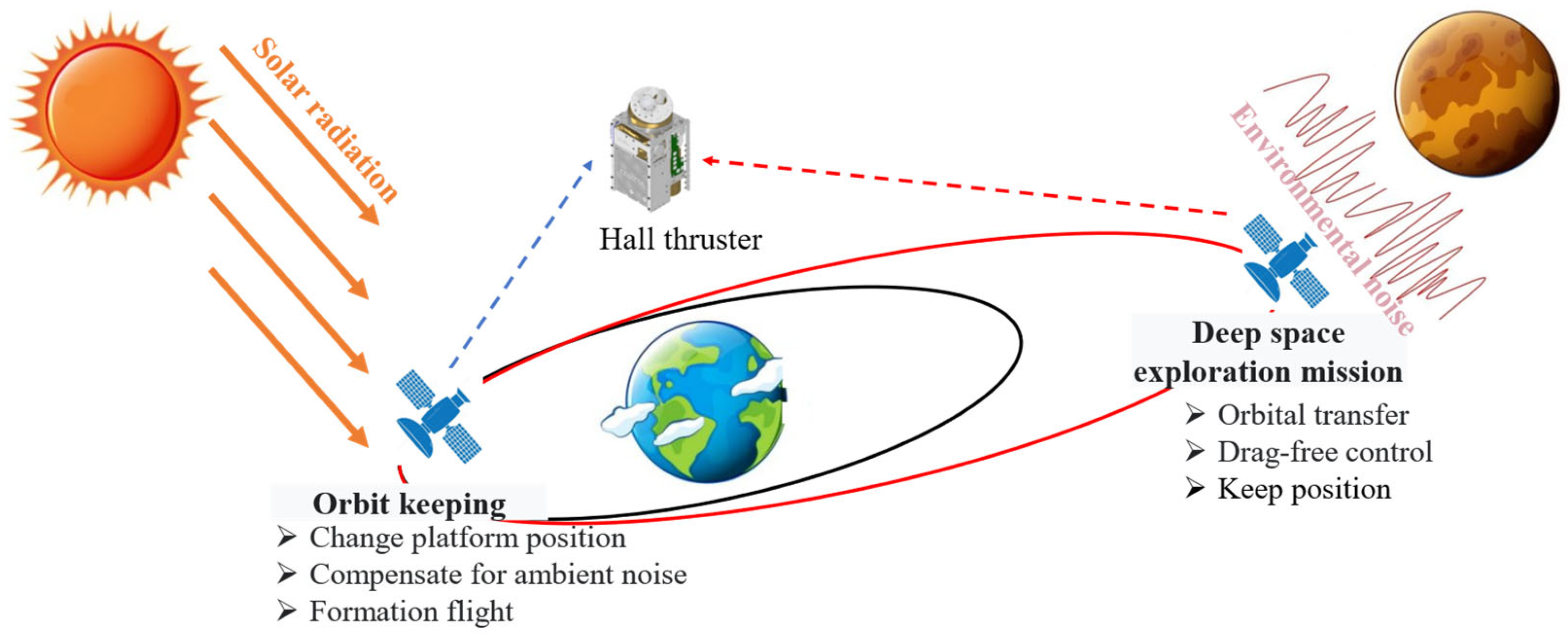
The propulsion system is a typical executive component of a satellite control system as it provides the power. Many civilian and military space missions have boosted the development of micro propulsion systems, which include Laser Interferometer Space Antenna (LISA), the Lunar Ice Cube Mission, and the Power and Propulsion Element (PPE) of the Lunar Orbital Platform-Gateway (LOP-G) [5]. Moreover, many of the Low Earth Orbit (LEO) and Geostationary Transfer Orbit (GEO) satellites have employed electric propulsion (EP) in their propulsion systems [6]. The Hall thruster is being considered for deep space exploration due to the increasing number and complexity of tasks that are now involved. This technology is advantageous because it provides a high thruster-to-power ratio and requires less power supply [7,8]. The conventional Hall thruster, despite its widespread use, has encountered challenges in achieving stable and low-noise operation, which can impact its thrust adjustability and suitability for specific tasks like gravitational wave detection missions. In the latest LISA (Laser Interferometer Space Antenna) mission concept proposal, only three electric thrusters were recommended for drag-free control: colloid thrusters, radio frequency ion thrusters, and cusped field thrusters. These thrusters have been identified as potential candidates due to their ability to maintain stable and precise control for the mission’s requirements [9]. These thrusters have been identified as potential candidates for addressing the specific requirements of drag-free control tasks and maintaining a stable operation under the mission’s conditions, as Figure 1 shows. Typically, a thruster that is employed in the Laser Interferometer Space Antenna (LISA) mission must be capable of operating for a period of 10,000 h [10].
High-energy particles can sputter the surface materials of a channel’s walls, which can increase the erosion rate of the thruster [11]. The cusped field thruster (CFT) has demonstrated capabilities that align with the demands of gravitational wave detection missions in terms of thrust range, resolution, and noise levels. As a result, the CFT is chosen as the primary focus of this study. It shares similarities in structure with the Hall thruster, and the literature also indicates that there are similar failure mechanisms between the two [12,13,14,15]. As the main part of the CFT system, channel erosion can seriously affect the thruster system’s lifetime. Therefore, the channel depth is a key performance indicator of the thruster [12].
The data on thruster degradation are difficult to obtain, especially failure data, which are not only resource intensive to obtain, but also time consuming. CFT reliability is a costly subject due to the small sample size of the available studies, and obtaining no-fault data in most situations can be challenging [16]. This makes it difficult to evaluate the reliability and to explore the complex failure modes of a CFT. Therefore, although researchers have proposed various methods and models to predict the erosion rate and lifetime of thrusters, the reliability aspect is often overlooked [17,18,19]. To address the challenge of small sample sizes in the context of CFT reliability testing during gravitational wave detection missions, this paper proposes a combined method for reliability calculation. The structure of the paper is as follows: Section 2 provides a brief overview of the CFT operation principle and discusses the mechanism of erosion. Section 3 presents the proposed new model and experimental setup. Section 4 analyzes a case study of thruster reliability.
2. Cusped Field Thruster
The cusped field thruster (CFT) is an innovative concept in electric propulsion that operates on the principle of ion motion in an electric and magnetic field. Figure 2 illustrates the schematic diagram of a CFT. In this thruster geometry, the electrically biased metallic anode is positioned at the base of the channel where the propellant gas is injected into the thruster. The magnets are arranged opposite each other to produce a magnetic field at the channel wall, which consists of samarium cobalt (SmCo). The propellant, typically xenon, is introduced into the channel through a flow tube near the anode, and electrons are accelerated under the right-handed circularly polarized wave. The electrons, which are used for generating the cascade seeds and neutralizing the ion beam, are provided by the cathode.
The experiment object is a micronewton-cusped field thruster designed for gravity field measurement tasks. It is shown in Figure 2b. The discharge channel of this thruster is cylindrical and made of boron nitride ceramics. The thruster utilizes two stages of permanent magnetic rings to establish a cusped magnetic field within the channel. The positioned upstream of the thruster channel is a stainless-steel anode, while the cathode is located downstream of the thruster outlet, thereby serving as the source of electrons. The electrons within the channel are constrained by the cusped magnetic field, where they execute back-and-forth movements along the magnetic lines, which are influenced by the magnetic mirror force and the electric field force. As the electrons traverse the channel, xenon atoms supplied from the flow system undergo collisions and ionization, thus resulting in the generation of ions. The electrons proceed toward the anode, initiating a discharge through multiple collisions. To verify the performance of the thruster, we obtained measurements on the key thruster performance parameters relevant to gravitational wave detection tasks. The results are shown in Table 1 below, where represents a micronewton and represents a millisecond.
Sputtering is a plasma–material interaction phenomenon that occurs when the atoms of the channel wall material are ejected due to bombardment by heavy particles with sufficient kinetic energy. This phenomenon is primarily driven by the momentum exchange between the energetic particles and atoms of the wall material. The amount of sputtering experienced by CFT wall materials is typically quantified by the erosion rate (or yield), which is the measured volume of ejected surface material per unit of incident ions integrated over time. The transport model is a commonly used method for evaluating sputtering-induced erosion in a CFT, and it provides a satisfactory conceptual framework for understanding the underlying mechanisms [20]. The transport theory can be described in the following three main stages: (1) the exchange in energy that occurs between the energetic particles and material atoms, (2) the impacted material atoms that transfer energy to the other material atoms, and (3) the atoms near the material surface that are ejected when their energy exceeds the binding energy [21]. The transport theory sputtering mechanism is illustrated in Figure 3.
Yamamura and Tawara provided a general function tethered by experimental data—the semiempirical sputtering yields model [22]. The sputter yield is dependent on various factors, including the angle and energy of incident particles, the mass of incident and target particles, and the binding energy of atoms in the channel wall [23]. Sputter yield is an appropriate way to describe this process quantitatively [24]. The sputter yield can be calculated as follows [25]:
in which are the incident ion energy and angle, respectively. Here, k and are the fitting parameters, and is the threshold energy for sputtering. Table 2 shows a typical parameter setting of the materials. Y is the sputtering yield in cubic millimeter per Coulomb incident ion current. As Table 2 shows, Yalin et al.’s dataset was introduced and the data were collected by the same method, and the material used was pure BN and silica. The 60% boron nitride (BN) and 40% silicon dioxide (SiO2) materials were provided by Gamero-Castano and Katz, and the data were fitted by the experiments conducted by Garnier et al. The yield can be modeled by parameter and Equation (1).
3. Method to Establish the CFT Reliability
3.1. The Combined Method for CFT Thruster Erosion
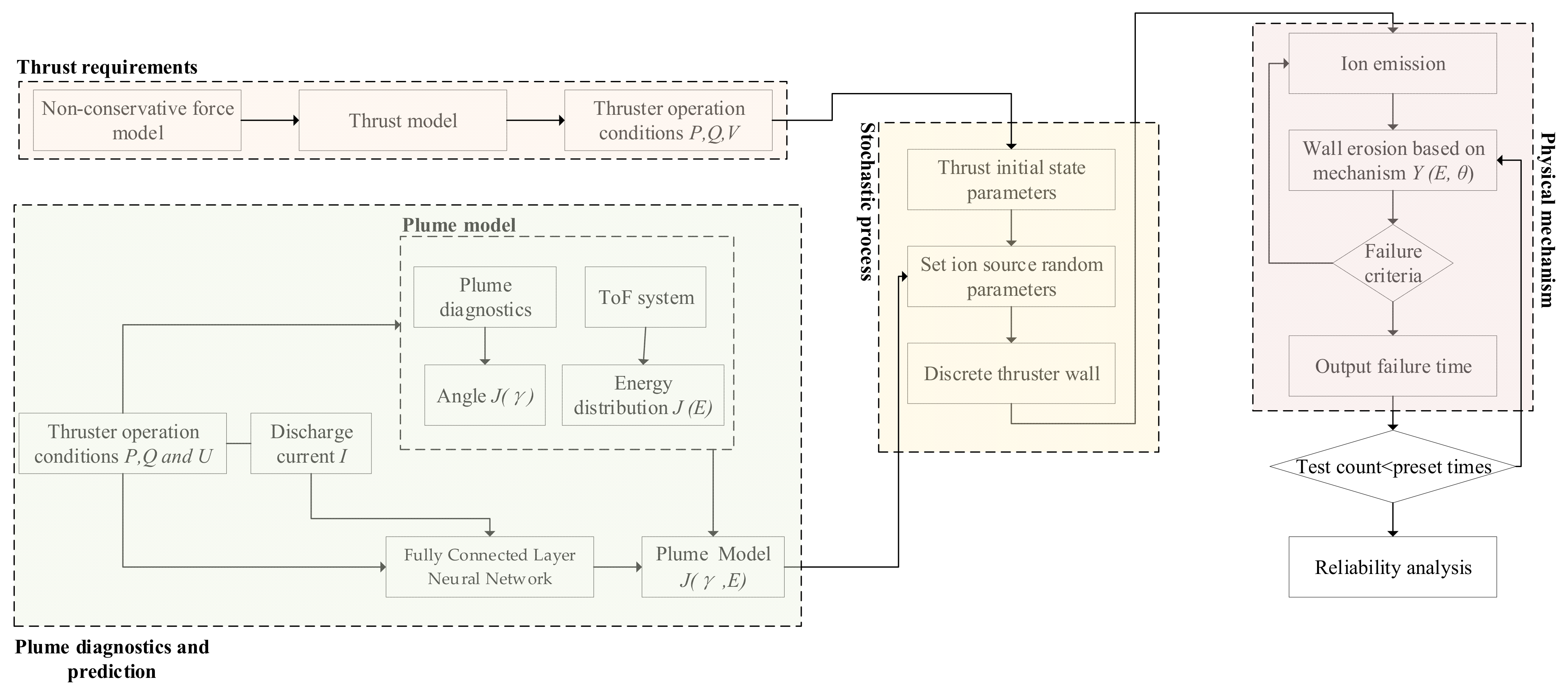
To combine the benefits of physical modeling and experimental approaches while overcoming some of their limitations, we propose a novel hybrid framework for thruster reliability that integrates physics-based performance models with empirical data, as depicted in Figure 4. Our proposed model is mainly composed of four parts, including thrust requirements, plume diagnostics and prediction, stochastic process simulation, and physical failure mechanisms. The plume diagnostics will be introduced in Section 3.2 and Section 3.3, while the thrust requirements will be covered in Section 3.4.
We propose a novel hybrid framework for modeling the reliability of a CFT thruster by combining the advantages of physical modeling and empirical approaches while overcoming some of their limitations. The structure of a CFT in a cylindrical coordinate system is shown in Figure 5.
The erosion of a channel wall occurs due to the impact of an ion flow. The rate of erosion can be characterized by volumetric sputtering, which is a measure of the volume of material that is ejected per unit of incident ion flow. The volume of sputtering, denoted as V over time t, and the volumetric sputtering yield, which is dependent on the properties of the channel wall, can be modeled using Equation (2) [28]:
where the expression can also be described via differential equation by
with
Here, is the sputter yield of the incident energy and angle , and . Nonetheless, this formulation is useful for establishing the reliability of a CFT. As Section 2 details, the thruster lifetime can be modeled via the criterion of depth limitation. Then, the general reliability analysis method can be used to evaluate the CFT reliability with respect to time.
3.2. Plume Diagnostics
To measure the angle and to calculate the energy of the thruster, the plume is characterized using a time of flight (ToF) system, as illustrated in Figure 6. The system contains ToF gates and a ToF collector, with the thruster operating upstream of the ToF gate.
The primary objective of the gate is to control the passage of ions based on the applied voltage. When the gate is at a high voltage, it acts as a barrier, thus preventing the ions from passing through. Conversely, when the gate is at a low voltage, it allows the ions to flow toward the collectors. The gate is constructed using evenly spaced metallic wires with a spacing of 1 mm. It is then connected to a 3000 V pulse amplifier that is driven by a pulse generator. The collectors are composed of metallic plates measuring 10 mm in diameter. These plates are connected to an oscilloscope through the utilization of a high-impedance signal amplifier. From the energy conservation, the mass m per unit charge of a flying particle is as follows [29]:
where L represents the distance of the flight, t represents the time taken to travel the distance L, and V0 corresponds to the retarding voltage (relative to the ground thruster) at which the actual velocity is reduced to zero.
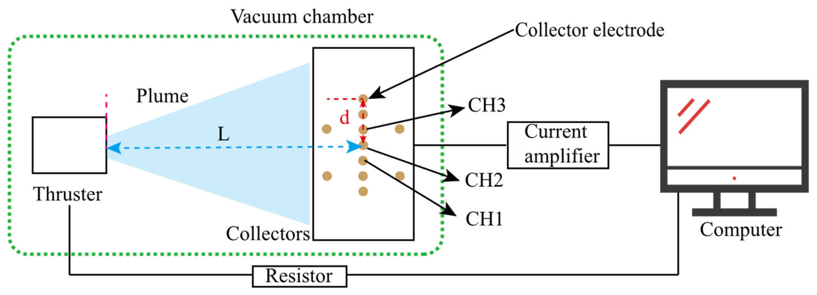
To measure the plume angle, we used an array collector plate consisting of 11 collection electrodes. A schematic diagram illustrating the principle is shown in Figure 7. There was a collection electrode with a diameter of 10 mm in front of the collector plate, which was followed by a wire connected to the current amplification circuit. Additionally, we can calculate the current of the thruster discharge using the formula I = U/R, where U is the voltage of the test and R is the resistor value used in the experiment. Through this device, we were able to obtain the current of the plume at different positions. The data of the current with distance were fitted by quadratic curve. By identifying the position where the current is zero, we can determine the divergence angle of the plume as .
3.3. Artificial Neural Network
The artificial neural network (ANN) is a machine learning technique that has gained significant popularity in recent years. Due to the high complexity of a CFT system, which arises from multiple factors as discussed previously, the utilization of artificial neural networks (ANNs) for non-linear analysis provides a distinct advantage in forecasting plume characteristics [30].
The artificial neural network (ANN) architecture consists of multiple layers of neurons, including the input layer, hidden layers, and the output layer, as illustrated in Figure 8. The number of neurons in the input and output layers is determined by the respective number of input and output variables. The selection of hidden layers and the number of neurons in each layer is based on the specific training task and performance requirements. It is generally recommended to avoid an excessive number of neurons in each layer as it may lead to overfitting and a decrease in model accuracy. Analyzing the operational characteristics of the thruster, it was observed that the CFT input power controls the initial plasma density, while the flow rate of the propellant directly impacts the density of the extracted beam particles. Consequently, the investigated operating parameters for the CFT primarily include the microwave input power P, propellant flow rate Q, and anode voltage U, thus resulting in three input neurons. The target parameter for prediction was the thrust of the CFT, which can also be used to calculate the specific impulse. Therefore, a single-output neuron was employed to capture this parameter.
3.4. Drag-Free Non-Conservation Force Modeling
The true thrust of a spacecraft is designed around the orbit required and non-conservative forces. In this section, a brief algorithm of thruster requirements is described. For a gravitational wave detection mission, the orbit configuration has an eccentricity ϵ and inclination ψ The satellite’s initial position conditions can be defined in the following [31]:
where ; R is the orbital radius; R = 1 A.U; l is the nominal arm length; is the orbital eccentricity; and is the eccentric anomaly, which can be defined as , where is /year. The acceleration at a specific point can be calculated by the second derivate of a position as . Then, the required acceleration can be calculated.
The restriction of non-conservative forces is the main obstruction for a gravitational wave detection mission. The complexity of the spacecraft’s geometry limits the model of the non-conservative force efficiency and precision. For the convenience of calculation, the small non-conservative force effects are ignored, including electromagnetic interference, radiation, etc.
The non-conservative forces that were modeled include the following [32]. Solar Radiation Pressure (SRP): this force arises when solar photons impact the spacecraft, and it relates to the momentum exchange that then occurs between the photons and spacecraft. This force can be modeled by
where is the exposure factor, is the solar pressure, is the reflection coefficient, is the area of irradiation, and is the unit vector from center of the earth to the sun. Thermal Re-Radiation: this forces arises when the satellite re-emits energy when a particular surface is heated by solar energy. The value of re-radiation depends on its reflectivity, absorptivity, and transmissivity parameters, which can be formulated by
where is the surface’s emissivity parameter, is the Boltzmann constant, is the area, is the speed of light in a vacuum, and is unit vector for the surface. The total force of non-conservation can be formulated by . The other non-conservative forces can be modeled by a normal distribution as N~(0, 1 × 10⁻⁵).
The required force can be calculated by . The acceleration of the requirement was calculated as mentioned above. The operation condition in this part is described by Equation (9) [14]:
in which F represents the thrust; are the flow rate and anode voltage, respectively; and are the coefficients detailed in Table 3.
4. Results and Discussion
4.1. The Validation of the Model
The input layer of the neural network model receives the operating parameters of the thruster. Through the activation function of the neurons in each layer, the calculated current is obtained as the final weighted sum of the neural outputs. Extensive data training enables continuous updates of the parameters for each node in the network, which is achieved by employing the error backpropagation algorithm to minimize the deviation between the calculated results and the actual values. To assess the accuracy of the predictions, the trained artificial neural network models (ANNs) are utilized to predict the current values for the ten distinct groups within the test dataset. The ANN model, illustrated in Figure 8, was composed of one input layer, two hidden layers, and one output layer.
The predicted results were then compared to the corresponding measured data, as presented in Figure 9. The red lines represent the experimental test values, and the distance between the predicted values and the red lines indicates the error, where greater distances indicate larger errors. It was observed that the current values predicted by the ANN model deviated by approximately 10% from the measured data.
4.2. Lifetime and Reliability in a Gravitational Wave Detection Mission
As shown in Section 3.3, a typical gravitational wave orbital non-conservative force model was established, and its individual component results are illustrated in Figure 10. Based on the non-conservative force results, a study was conducted on the corrosion depth under different operating conditions. With the voltage and flow rate fixed, the required adjustments for another operating condition can be calculated using the thrust model. Furthermore, the operating conditions beyond the specified time of the model were treated with periodic boundary conditions, as the orbital model exhibited periodic behavior.
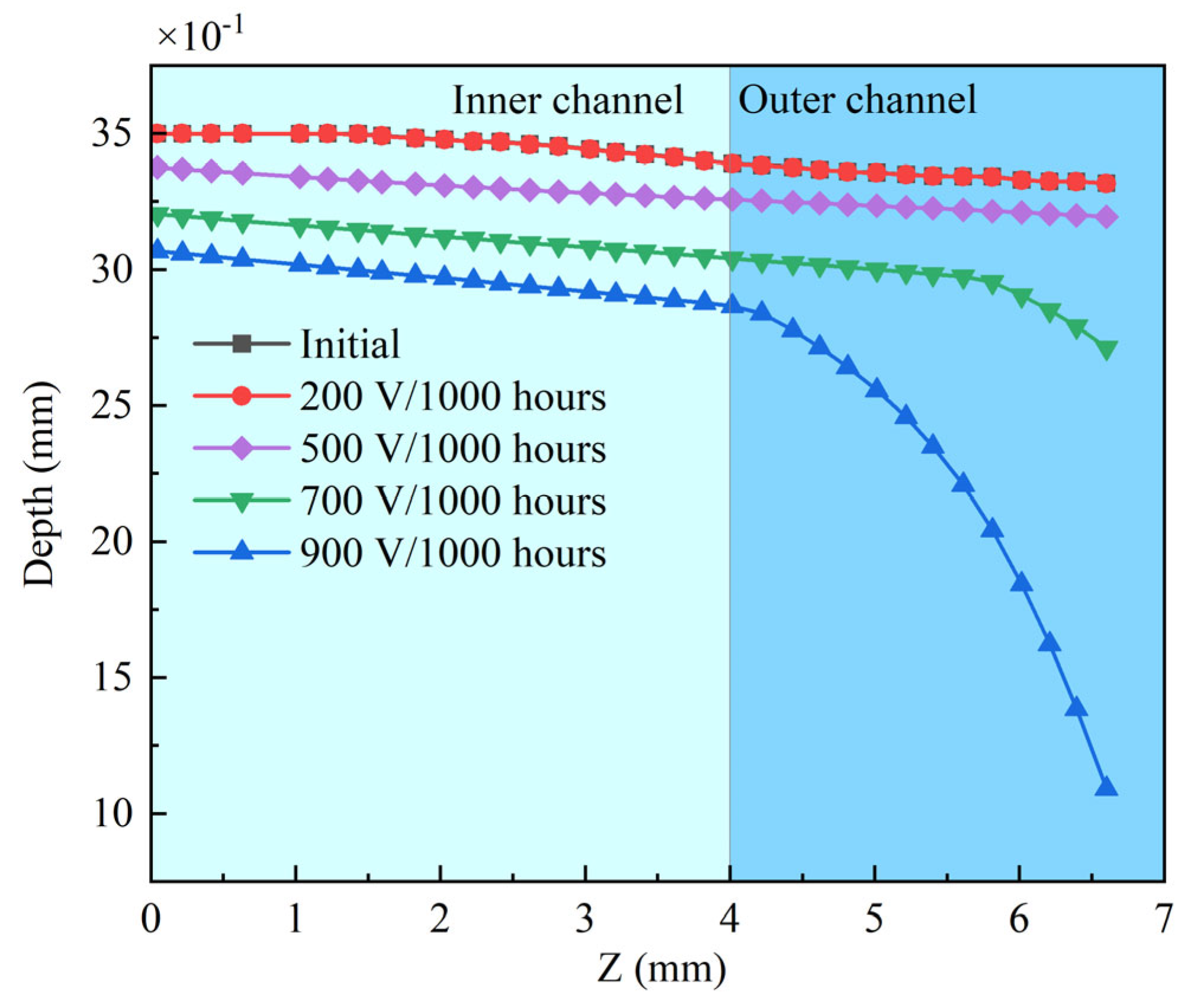
In the non-conservation force model, the flow rate can be determined using Equation (9), and the corresponding results are presented in Figure 11 for the fixed voltages of 200 V, 500 V, 700 V, and 900 V. The process on the computer (Intel(R) Xeon(R)CPU E3-1225 v6 @ 3.30 GHz (4 CPUs), ~3.3 GHz, Intel, Santa Clara, CA, USA) took only 5 min for each erosion topology; thus, compared to the 7 h detailed in the literature required for the PIC method [18], it achieved a faster speed. The erosion depth exhibited an increasing trend with a rise in voltage, and the rate of increase gradually accelerated. The erosion became evident once the voltage surpassed 500 V, as it indicated the presence of a sputtering threshold in the material. This threshold signified the onset of erosion processes that occur only after a certain voltage level is reached. As Figure 11 shows, the outer liner exhibited a greater susceptibility to erosion compared to the inner liner, particularly at higher voltages. This can be attributed to the outer liner having a higher number of sputter angle coefficients, which enhances the erosion phenomenon.
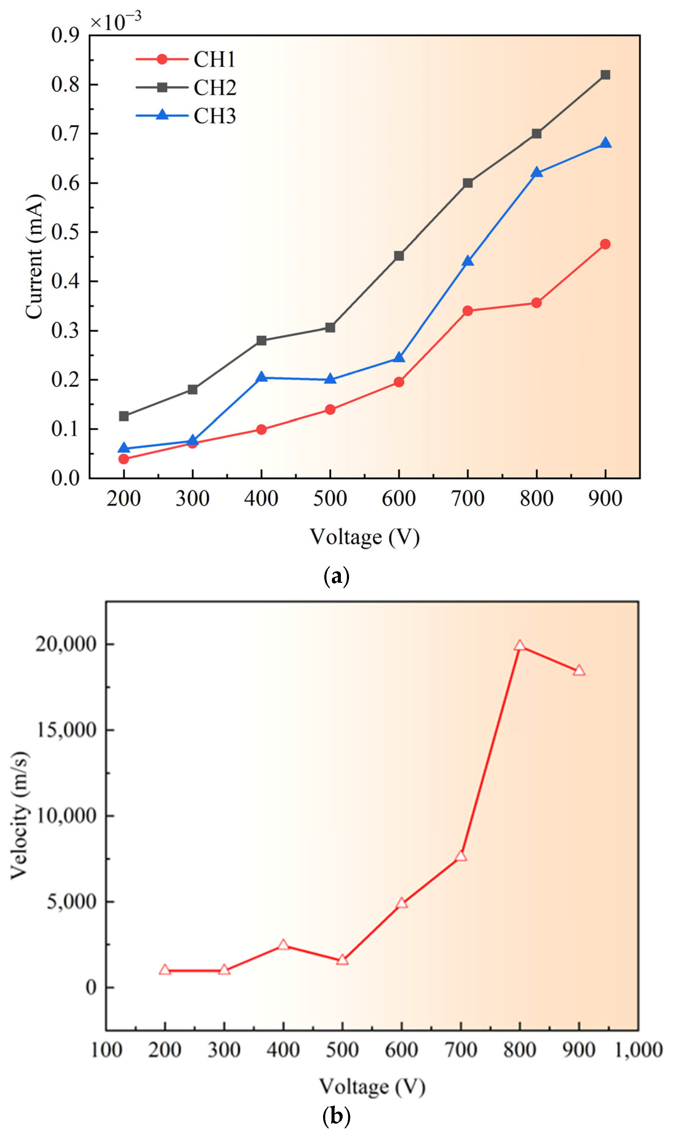
As shown in Figure 12, as the voltage increased, the current received by the TOF electrode also gradually rose. This indicates that increasing the voltage leads to a higher ion density. Additionally, due to the increasing potential difference between the anode and the outer channel, the ions gained more energy, thereby resulting in an increase in their velocity, as shown in Figure 12b. As illustrated in Figure 12b, there was only a modest increase in the ion velocity when the voltage was below 600 V. This can be attributed to the majority of the voltage’s energy being utilized for ionization, with only a small fraction contributing to ion acceleration. However, once the voltage surpassed 600 V, the ion velocity experiences a significant and rapid growth. This can be attributed to the augmented energy release at higher voltages, which leads to accelerated ion motion. Furthermore, this phenomenon sheds light on the observation in Figure 11, where the outer discharge channel undergoes intensified erosion when the voltage exceeds 500 V. The accelerated ions, resulting from higher voltages, are more prone to induce severe corrosion in the outer discharge channel. Also, with increasing voltage, the current rose owing to the heightened proportion of multiple charged ions and their augmented flow velocity, as shown in Figure 11.
In order to study the influence of the propellant flow rate on thruster erosion, we adopted a similar methodology to investigate the effects of the varying flow rates. As illustrated in Figure 13, we kept the flow rate constant, and the thrust was generated from non-conservative forces, thus allowing us to calculate the voltage values. With the increase in flow rate, the corrosion depth of the thruster’s wall surface showed little variation. This phenomenon can be attributed to the relatively small thrust generated by non-conservative forces. Consequently, under higher-flow-rate conditions, the theoretical voltage required is lower, resulting in ions possessing less energy that fail to exceed the threshold of the sputtering erosion model. As a consequence, the impact on the thruster’s wall surface remains minimal, and the erosion is limited even at higher flow rates. As shown in Figure 13, an increase in flow rate leads to a corresponding increase in the thrust generated by the thruster. This can be primarily attributed to the greater number of propellant particles involved in the ionization process within the thruster. However, due to the constraints imposed by the required thrust, the acceleration voltage needed remains relatively low (around 100 V). As a result, most xenon ions do not possess sufficient energy to exceed the threshold for material sputtering. Consequently, the increase in flow rate has little impact on the erosion of the surface morphology.
In accordance with Figure 14, this study delved further into examining the temporal evolution of erosion morphology within the discharge channel of a 500 V thruster. During the initial 2000 h, the surface morphology of the thruster exhibited only thickness variations without any significant alterations in shape. However, beyond the 2000 h mark, conspicuous changes in the morphology of the discharge channel became evident. In particular, a more severe erosion occurred on the outer side of the discharge channel (around 4 mm to 7 mm), while the inner region (around 0 mm to 4 mm) remained relatively unaffected. These observed morphological changes align with the existing literature on the subject. At the 5000 h point, the corrosion depth within the discharge channel’s inner region (around 0 mm to 4 mm) measured approximately 0.49 mm, while the maximum erosion depth on the outer side reached approximately 3.1 mm.
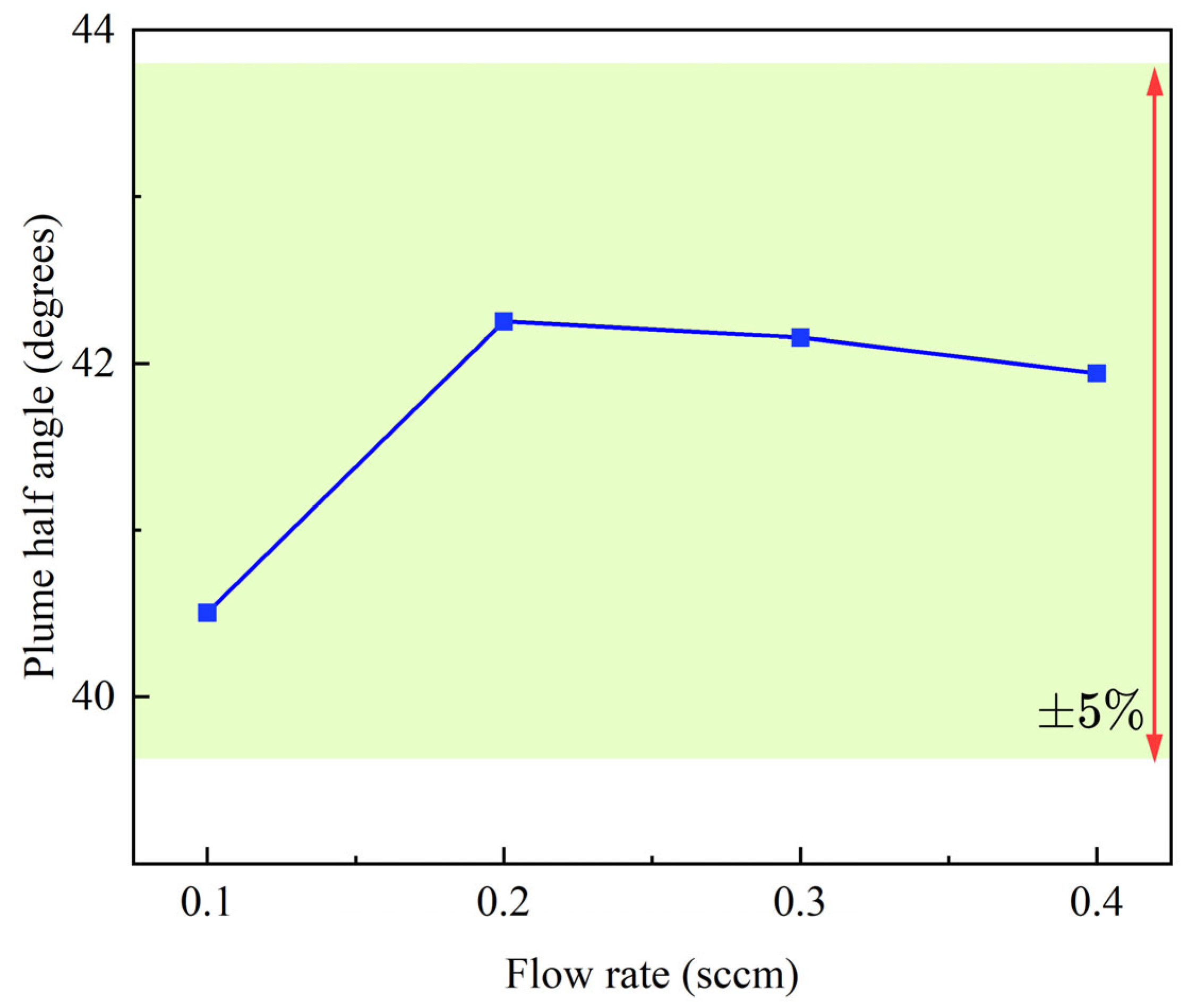
It is noteworthy that the two curves almost coincided as the ion flux decreased during the declining phase of flow demand at 3000 and 4000 h. Subsequently, the continued decrease in flow demand may lead to a mode transition in the thruster, thereby resulting in an increase in its plume divergence angle.
Upon comparing Figure 14 and Figure 11, it is evident that the voltage and time have similar underlying mechanisms. At low voltages, the outer periphery of the discharge channel does not experience significant erosion, thus resulting in a relatively uniform erosion rate akin to the situation observed before 2000 h. As the voltage increased, the ions gained more energy, thereby leading to intensified erosion on the outer periphery of the discharge channel, which was similar to the phenomenon observed after 3000 h. Two primary factors contributed to this trend: First, an increase in the voltage led to a larger divergence angle of the thruster’s plume, making the wall of the discharge channel more susceptible to erosion as the voltage increased. Second, the effect of time can be attributed to the larger angle between the outer wall of the discharge channel and the plume, which makes the outer wall more prone to erosion due to the higher intensity of the angular sputtering.
In order to establish a reliability model for the thruster, this study employed the KM (Kaplan–Meier) method to construct a non-parametric estimation reliability model. The lifetime was defined as the time at which the wall thickness reaches 0 mm. The results of the thruster’s discharge channel showed minimal signs of damage in the initial 7000 h of operation, as depicted in Figure 15. However, during the period from 7000 to 8000 h, some cases exhibited a partial erosion of the channel walls. Despite this, there was still a probability of over 80% that the thruster could continue to operate during this time frame. Beyond 8000 h, the probability of the discharge channel remaining undamaged started to decrease rapidly, thus indicating that the thruster entered a more critical and potentially risky phase of operation.
5. Conclusions
This study addresses the problem of the small sample size in the field of CFT reliability by proposing a method that combines physical mechanisms with experimental analysis to evaluate the reliability of a CFT when undertaking a gravitational wave detection mission. The model developed in this study is based on a sputtering mechanism and experimental fit, and computer simulations were used to generate the erosion data and reliability analysis of the CFT.
The method proposed in this study is faster and more efficient due to the combination of physical and experimental models. Furthermore, a detailed investigation of the erosion process of a typical cusped field thruster (CFT) was conducted, and the reliability assessment was performed using the Kaplan–Meier (KM) method. This study further indicates that the erosion depth on the inner side of the thruster is less than that on the outer channel wall, thereby emphasizing the need for a careful consideration of the magnetic shape design for the outer wall. Additionally, the analysis helped to evaluate the influence of different operational conditions on the CFT’s lifespan in the context of a gravitational wave detection mission.
To optimize the thruster’s lifespan, it is recommended to design control algorithms that prioritize low-voltage and high-flow-rate conditions. This choice is motivated by the fact that the impact of voltage-induced energy on the system is more significant compared to the effect of the flow rate. By operating at a low voltage and high flow rate, the thruster experiences less energy shock, leading to a reduced erosion and extended lifespan. Thus, adopting such operating conditions strategically enhances the thruster’s durability and overall performance.
Author Contributions
Conceptualization, formal analysis, and writing, Y.C. and S.C.; methodology, J.W. and Y.S. All authors have read and agreed to the published version of the manuscript.
Funding
This research was funded by the Shenzhen Key Laboratory of Intelligent Microsatellite Constellation (grant number ZDSYS20210623091808026), Guangdong Basic and Applied Basic Research Foundation (grant number 2021A1515110500).
Data Availability Statement
Data are contained within the article.
Conflicts of Interest
The authors declare no conflicts of interest.
References
- K Danzmann for the LISA Study Team. LISA—An ESA cornerstone mission for a gravitational wave observatory. Class. Quantum Gravity 1997, 14, 1399–1404. [Google Scholar] [CrossRef]
- Kawamura, S.; Nakamura, T.; Ando, M.; Seto, N.; Tsubono, K.; Numata, K.; Takahashi, R.; Nagano, S.; Ishikawa, T.; Musha, M. The Japanese space gravitational wave antenna—DECIGO. Class. Quantum Gravity 2006, 23, S125. [Google Scholar] [CrossRef]
- Luo, J.; Chen, L.-S.; Duan, H.-Z.; Gong, Y.-G.; Hu, S.; Ji, J.; Liu, Q.; Mei, J.; Milyukov, V.; Sazhin, M.; et al. TianQin: A space-borne gravitational wave detector. Class. Quantum Gravity 2016, 33, 35010. [Google Scholar] [CrossRef]
- Hu, W.-R.; Wu, Y.-L. The Taiji Program in Space for Gravitational Wave Physics and the Nature of Gravity; Oxford University Press: Oxford, UK, 2017; Volume 4, pp. 685–686. ISBN 2095-5138. [Google Scholar]
- Dervan, J.A.; Johnson, L.; McNutt, L.; Nuth, J.; Few, A.; Heaton, A.F.; Carr, J.; Boyd, D.; Turse, D.; Malphrus, B. New Moon Explorer (NME) Robotic Precursor Mission Concept. In Proceedings of the 2018 AIAA SPACE and Astronautics Forum and Exposition, Orlando, FL, USA, 17–19 September 2018; p. 5107. [Google Scholar]
- Lev, D.; Myers, R.M.; Lemmer, K.M.; Kolbeck, J.; Koizumi, H.; Polzin, K. The technological and commercial expansion of electric propulsion. Acta Astronaut. 2019, 159, 213–227. [Google Scholar] [CrossRef]
- Brown, N.P.; Walker, M.L.R. Review of Plasma-Induced Hall Thruster Erosion. Appl. Sci. 2020, 10, 3775. [Google Scholar] [CrossRef]
- Bapat, A.; Salunkhe, P.B.; Patil, A.V. Hall-Effect Thrusters for Deep-Space Missions: A Review. IEEE Trans. Plasma Sci. 2022, 50, 189–202. [Google Scholar] [CrossRef]
- Amaro-Seoane, P. Laser interferometer space antenna: A proposal in response to the ESA call for L3 mission concepts. arXiv 2017, arXiv:170200786. [Google Scholar]
- Wirz, R.E. Electrospray Thruster Performance and Lifetime Investigation for the LISA Mission. In Proceedings of the AIAA Propulsion and Energy 2019 Forum, Indianapolis, IN, USA, 19–22 August 2019; American Institute of Aeronautics and Astronautics: Indianapolis, IN, USA, 2019. [Google Scholar]
- Yu, D.; Li, Y.; Song, S. Ion Sputtering Erosion of Channel Wall Corners in Hall Thrusters. J. Phys. Appl. Phys. 2006, 39, 2205. [Google Scholar] [CrossRef]
- Gildea, S.R.; Matlock, T.S.; Martínez-Sánchez, M.; Hargus, W.A. Erosion Measurements in a Low-Power Cusped-Field Plasma Thruster. J. Propuls. Power 2013, 29, 906–918. [Google Scholar] [CrossRef]
- Courtney, D.G.; Martinez-Sanchez, M. Diverging cusped-field Hall thruster (DCHT). In Proceedings of the 30th International Electric Propulsion Conference, Florence, Italy, 17–20 September 2007. [Google Scholar]
- Cui, K.; Liu, H.; Jiang, W.; Yu, D. Thrust noise cause analysis and suppression of a cusped field thruster. Acta Astronaut. 2021, 179, 322–329. [Google Scholar] [CrossRef]
- Cui, K.; Liu, H.; Jiang, W.J.; Sun, Q.Q.; Hu, P.; Yu, D.R. Effects of Cusped Field Thruster on the Performance of Drag-Free Control System. Acta Astronaut. 2018, 144, 193–200. [Google Scholar] [CrossRef]
- Saleh, J.H.; Geng, F.; Ku, M.; Walker, M.L.R. Electric propulsion reliability: Statistical analysis of on-orbit anomalies and comparative analysis of electric versus chemical propulsion failure rates. Acta Astronaut. 2017, 139, 141–156. [Google Scholar] [CrossRef]
- Cao, S.; Wang, X.; Ren, J.; Ouyang, N.; Zhang, G.; Zhang, Z.; Tang, H. Performance and plume evolutions during the lifetime test of a Hall-effect thruster. Acta Astronaut. 2020, 170, 509–520. [Google Scholar] [CrossRef]
- Cho, S.; Komurasaki, K.; Arakawa, Y. Lifetime Simulation of an SPT-Type Hall Thruster by Using a 2D Fully Kinetic PIC Model. In Proceedings of the 48th AIAA/ASME/SAE/ASEE Joint Propulsion Conference & Exhibit, Atlanta, GA, USA, 30 July–1 August 2012. [Google Scholar]
- Zhang, Z.; Tian, Y.; Wang, P.; Wu, J. Experiment and calculation analysis of Hall thruster lifetime. J. Rocket Propuksion 2014, 40, 16–22. [Google Scholar]
- Yim, J.T. Computational Modeling of Hall Thruster Channel Wall Erosion. Ph.D. Thesis, University of Michigan, Ann Arbor, MI, USA, 2008. [Google Scholar]
- Murty, M.R. Sputtering: The material erosion tool. Surf. Sci. 2002, 500, 523–544. [Google Scholar] [CrossRef]
- Yamamura, Y.; Tawara, H. Energy dependence of ion-induced sputtering yields from monatomic solids at normal incidence. At. Data Nucl. Data Tables 1996, 62, 149–253. [Google Scholar] [CrossRef]
- Eagle, W.; Boyd, I.; Trepp, S.; Sedwick, R. The Erosion Prediction Impact on Current Hall Thruster Model Development. In Proceedings of the 44th AIAA/ASME/SAE/ASEE Joint Propulsion Conference & Exhibit, Hartford, CT, USA, 21–23 July 2008. [Google Scholar]
- Nishii, K.; Clark, S.; Nuwal, N.; Levin, D.A.; Rovey, J.L. Numerical Simulation of Carbon Sputtering for Electric Propulsion in the Ground Facility. In Proceedings of the 37th International Electric Propulsion Conference, Boston, MA, USA, 23 June 2022. [Google Scholar]
- Schinder, A.M.; Walker, M.; Rimoli, J.J. Three-Dimensional Model for Erosion of a Hall-Effect Thruster Discharge Channel Wall. J. Propuls. Power 2014, 30, 1373–1382. [Google Scholar] [CrossRef]
- Gamero-Castano, M.; Katz, I. Estimation of Hall Thruster Erosion Using HPHall; Jet Propulsion Laboratory, National Aeronautics and Space: Pasadena, CA, USA, 2005.
- Yalin, A.; Rubin, B.; Domingue, S.; Glueckert, Z.; Williams, J. Differential sputter yields of boron nitride, quartz, and kapton due to low energy Xe+ bombardment. In Proceedings of the 43rd AIAA/ASME/SAE/ASEE Joint Propulsion Conference & Exhibit, Cincinnati, OH, USA, 8–11 July 2007; p. 5314. [Google Scholar]
- Lovtsov, A.; Shagayda, A.; Gorshkov, O. Semi-empirical method of hall thrusters lifetime prediction. In Proceedings of the 42nd AIAA/ASME/SAE/ASEE Joint Propulsion Conference & Exhibit, Sacramento, CA, USA, 8–12 July 2006; p. 4661. [Google Scholar]
- Courtney, D.G.; Dandavino, S.; Shea, H. Comparing Direct and Indirect Thrust Measurements from Passively Fed Ionic Electrospray Thrusters. J. Propuls. Power 2016, 32, 392–407. [Google Scholar] [CrossRef]
- Hassanien, A.E.; Darwish, A.; Abdelghafar, S. Machine learning in telemetry data mining of space mission: Basics, challenging and future directions. Artif. Intell. Rev. 2019, 53, 3201–3230. [Google Scholar] [CrossRef]
- Wang, G.; Ni, W.-T.; Wu, A.-M. Orbit design and thruster requirement for various constant arm space mission concepts for gravitational-wave observation. Int. J. Mod. Phys. D 2020, 29, 1940006. [Google Scholar] [CrossRef]
- Sibthorpe, A.J. Precision Non-Conservative Force Modelling for Low Earth Orbiting Spacecraft; University of London, University College London: London, UK, 2006; ISBN 1-303-36469-7. [Google Scholar]
Figure 1.
A Hall thruster of different satellite platforms.

Figure 2.
Micronewton-cusped field thruster. (a) Scheme of a cusped field thruster. (b) The micronewton-cusped field thruster (right: initiation).
Figure 2.
Micronewton-cusped field thruster. (a) Scheme of a cusped field thruster. (b) The micronewton-cusped field thruster (right: initiation).

Figure 3.
Sputtering mechanism according to the transport model.

Figure 4.
Method for evaluating the reliability of a CFT thruster.

Figure 5.
Erosion of a CFT.

Figure 6.
The time of flight system.

Figure 7.
Schematic diagram of a plume angle measurement.

Figure 8.
A fully connected layer neural network structure.

Figure 9.
The predicted results and measured data of the ANN.

Figure 10.
The results of the non-conservation force model.

Figure 11.
The relationships between the voltage and surface topological structure.

Figure 12.
The data of the TOF at different voltages. (a) The variation in the current in the three channels in relation to the different voltages. (b) The velocity variation at different voltages.
Figure 12.
The data of the TOF at different voltages. (a) The variation in the current in the three channels in relation to the different voltages. (b) The velocity variation at different voltages.

Figure 13.
The relationship between the flow rate and surface topological structure.


Figure 14.
Erosion depth of the channel wall from 0 to 5000 h.

Figure 15.
The failure rate against time as indicated by the Kaplan–Meier evaluation.


Table 1.
The performance of a micronewton CFT.
| Performance Parameters | CFT |
|---|---|
| ) | 1–100 |
| ) | 0.1 |
| ) | 0.1 |
| ) | 50 |
Table 2.
Parameters for a normal yield approximation.
| Material | k | B0 | B1 | B2 | B3 | Eth |
|---|---|---|---|---|---|---|
| Gamero-Castano and Katz, 60% BN and 40% SiO2 [26] | 1.00 | 0.0099 | 0 | 6.03 × 10⁻⁶ | −4.75 × 10⁻⁸ | 58.6 |
| Yalin, 99% BN [27] | 0.00228 | 1.18 | 0.0194 | 1.22 × 10⁻⁴ | −2.22 × 10⁻⁶ | 18.3 |
Table 3.
The non-conservation parameters.
| Parameter Name | Value |
|---|---|
| 4.56 × 10⁻⁶ N | |
| 1.2 | |
| 0.02 | |
| T | 298 K |
| AMLI | 0.67 m2 |
| AX | −1.218 |
| BX | −0.403 |
| CX | 1.562 × 10⁻⁴ |
| DX | 5.299 × 10⁻² |
| EX | −1.453 × 10⁻⁶ |
| FX | 3.897 × 10⁻⁴ |
Disclaimer/Publisher’s Note: The statements, opinions and data contained in all publications are solely those of the individual author(s) and contributor(s) and not of MDPI and/or the editor(s). MDPI and/or the editor(s) disclaim responsibility for any injury to people or property resulting from any ideas, methods, instructions or products referred to in the content. |
© 2024 by the authors. Licensee MDPI, Basel, Switzerland. This article is an open access article distributed under the terms and conditions of the Creative Commons Attribution (CC BY) license (https://creativecommons.org/licenses/by/4.0/).
Share and Cite
MDPI and ACS Style
Chen, Y.; Wu, J.; Shen, Y.; Cao, S. The Reliability Modeling and Evaluation of a Cusped Field Thruster When Undertaking a Gravitational Wave Detection Mission. Aerospace 2024, 11, 329. https://doi.org/10.3390/aerospace11050329
AMA Style
Chen Y, Wu J, Shen Y, Cao S. The Reliability Modeling and Evaluation of a Cusped Field Thruster When Undertaking a Gravitational Wave Detection Mission. Aerospace. 2024; 11(5):329. https://doi.org/10.3390/aerospace11050329
Chicago/Turabian StyleChen, Yu, Jianing Wu, Yan Shen, and Shuai Cao. 2024. "The Reliability Modeling and Evaluation of a Cusped Field Thruster When Undertaking a Gravitational Wave Detection Mission" Aerospace 11, no. 5: 329. https://doi.org/10.3390/aerospace11050329
Note that from the first issue of 2016, this journal uses article numbers instead of page numbers. See further details here.