Automatic Seam-Line Detection in UAV Remote Sensing Image Mosaicking by Use of Graph Cuts


Abstract
1. Introduction
2. Related Work
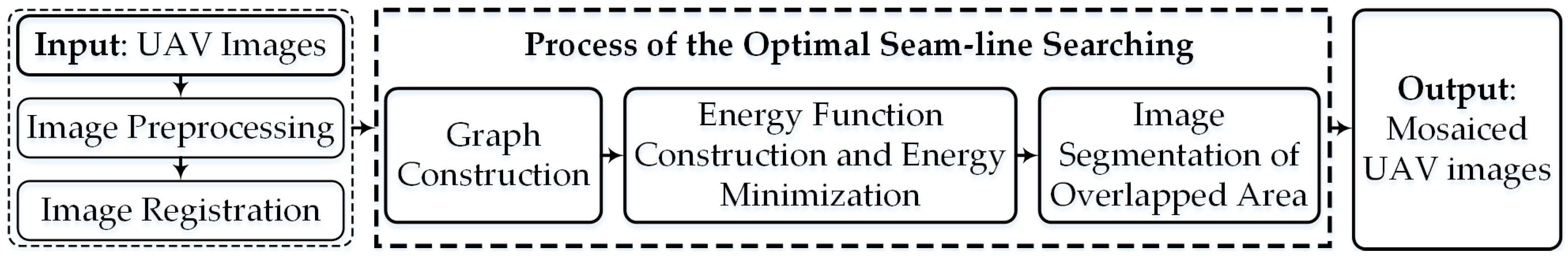
3. Method
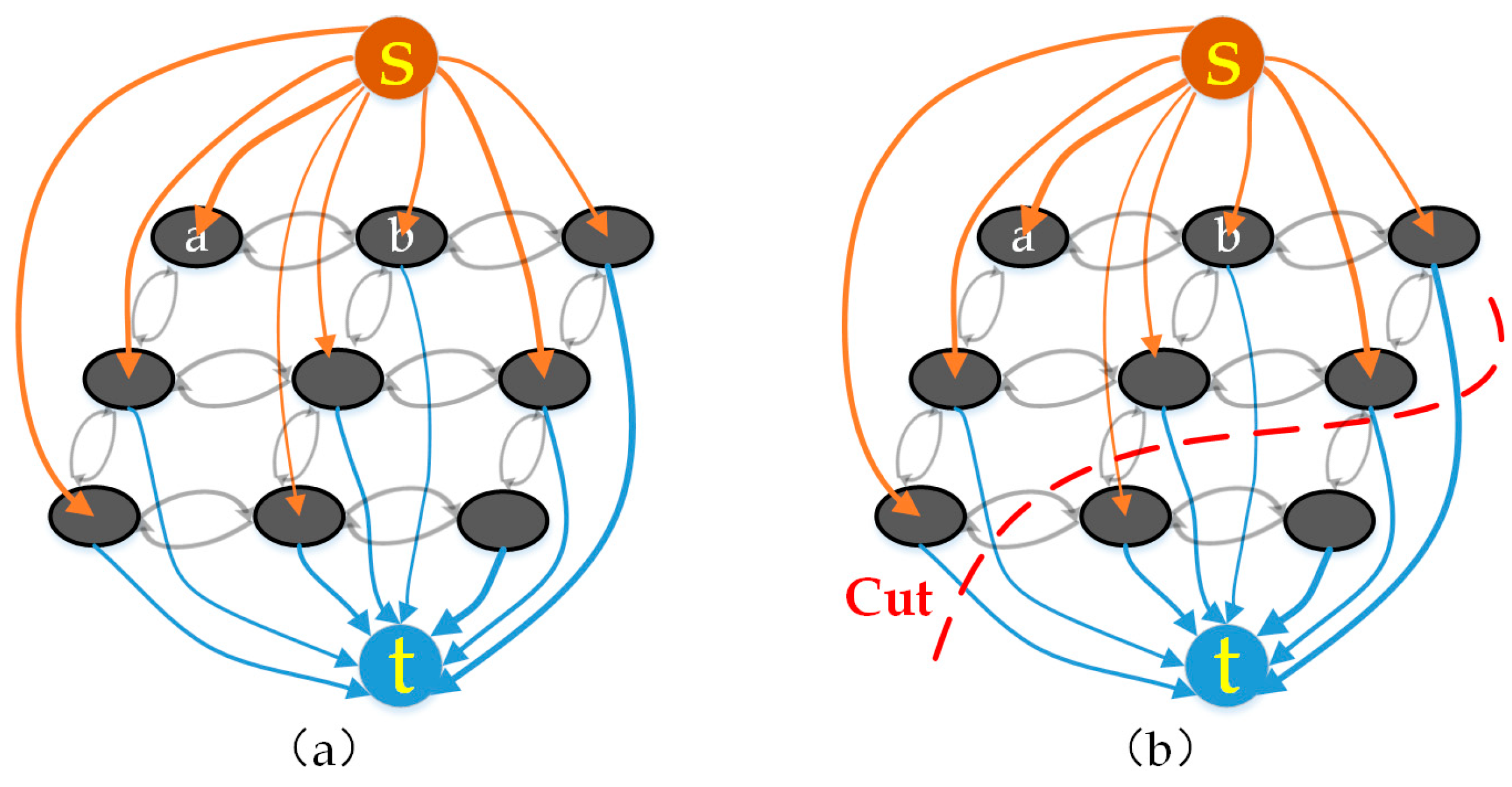
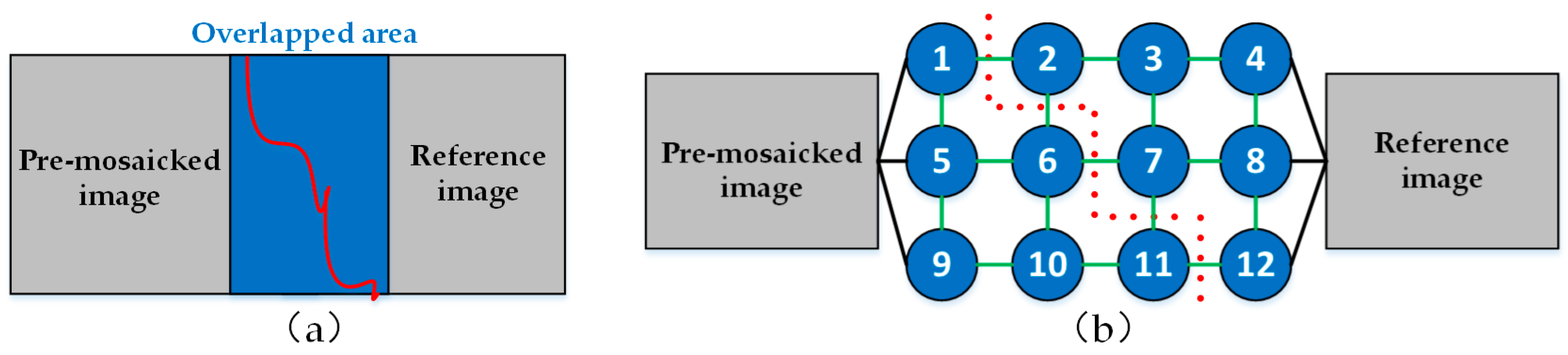
3.1. Classic Graph Cuts-Based Optimal Seam-Line Search Method from OpenCV Library
3.2. Improved Optimal Seam-Line Search Method Based on Graph Cuts
3.2.1. Optical Flow Field
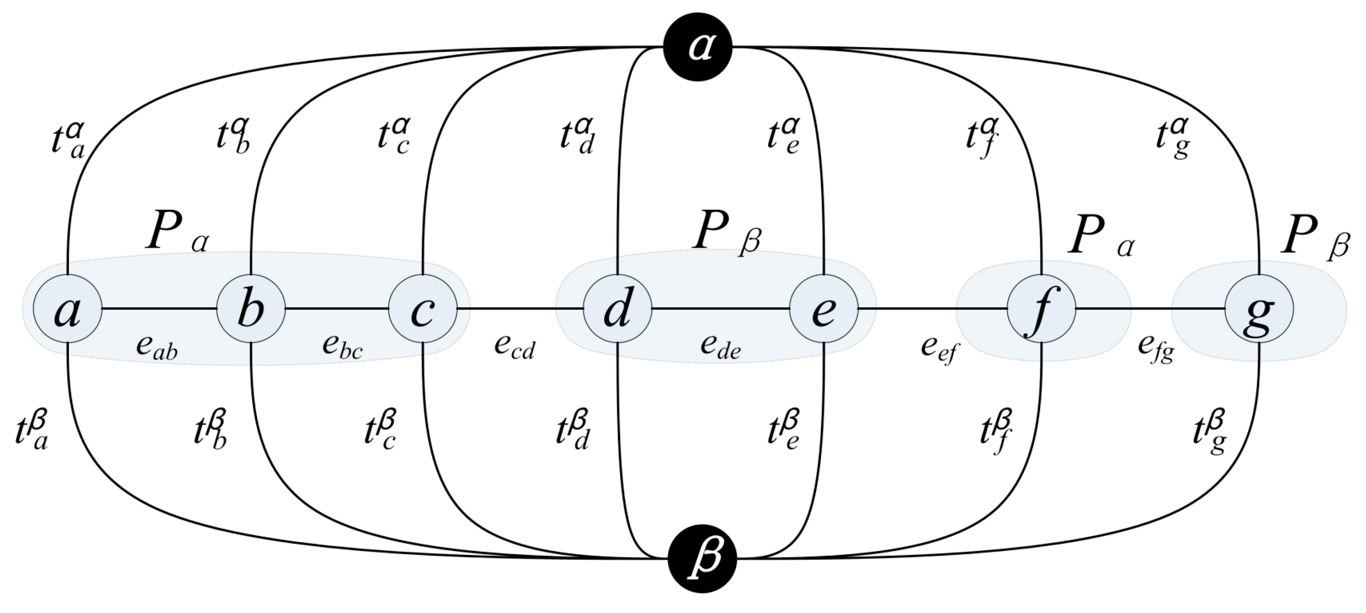
3.2.2. Graph Construction
3.2.3. Energy Function Definition
3.2.4. Solving Minimum Energy Value
4. Experiments and Evaluation
4.1. Experimental Data and Computing Environment
4.2. Experimental Results and Analysis
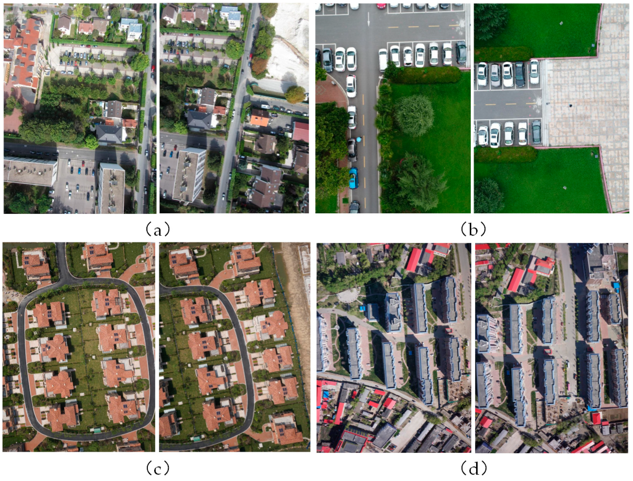
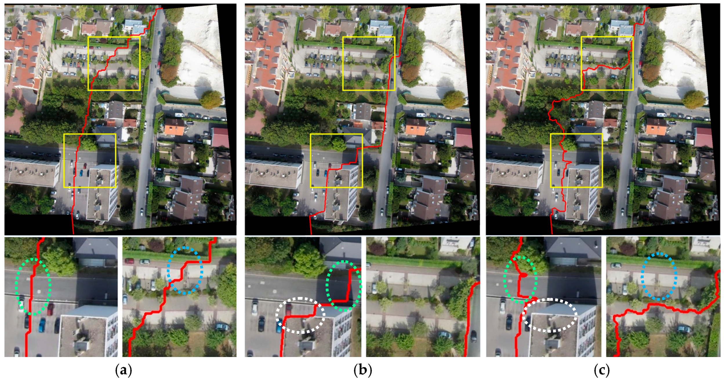
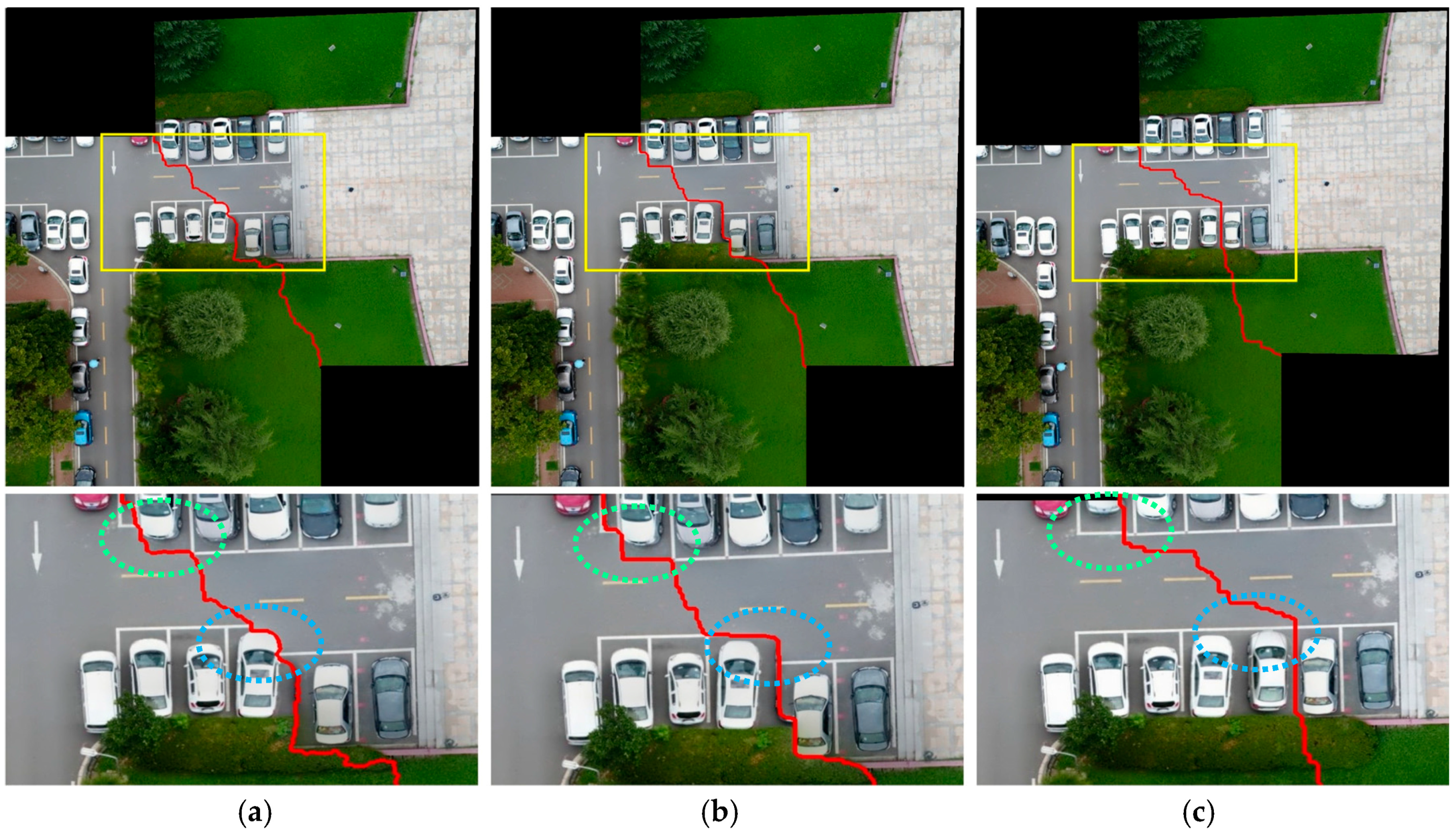
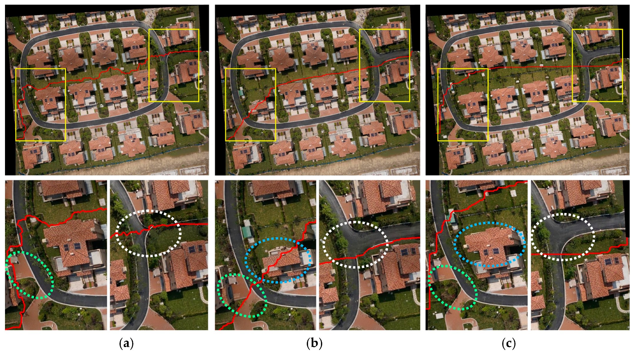
4.2.1. Comparison of UAV Image Mosaic Results Using Different Methods
4.2.2. Efficiency Comparison of Different Methods
5. Conclusions
Author Contributions
Funding
Conflicts of Interest
References
- Ghosh, D.; Kaabouch, N. A Survey on Image Mosaicking Techniques. Vis. Commun. Image Represent. 2016, 34, 1–11. [Google Scholar] [CrossRef]
- Byrne, J.; Keeffe, E.; Lenon, D.; Laefer, D. 3D reconstructions using unstabilized video footage from an unmanned aerial vehicle. J. Imaging 2017, 15, 1–15. [Google Scholar] [CrossRef]
- Pravenaa, S.; Methodical, R. A Methodical Review on Image Stitching and Video Stitching Techniques. Int. J. Appl. Eng. Res. 2016, 11, 3442–3448. [Google Scholar]
- Huang, Y.; Li, J.; Fan, N. Image Mosaicing for UAV Application. In Proceedings of the International Symposium on Knowledge Acquisition and Modeling, Wuhan, China, 21–22 December 2008; pp. 663–667. [Google Scholar]
- LI, D.; Li, M. Research advance and application prospect of unmanned aerial vehicle remote sensing system. Geomat. Inf. Sci. Wuhan Univ. 2014, 39, 505–513. [Google Scholar]
- Sun, H.; Li, L.; Ding, X.; Guo, B. The precise multimode GNSS positioning for UAV and its application in large scale photogrammetry. Geo-Spat. Inf. Sci. 2016, 19, 188–194. [Google Scholar] [CrossRef]
- Li, M.; Li, D.; Fan, D. A study on automatic UAV image method for paroxysmal disaster. Int. Arch. Photogramm. Remote Sens. Spat. Inf. Sci. 2012, XXXIX-B6, 123–128. [Google Scholar] [CrossRef]
- Zhang, Y.; Fu, H. A Method for Woodland Aerial Image Sequences Mosaic based on Iacunarity. J. Beijing For. Univ. 2017, 107–115. [Google Scholar]
- Chen, Z.; Zhang, L. An Aerial Image Mosaic Method Based on UAV Position and Attitude Information. Acta Geod. Cartogr. Sin. 2016, 45, 698–705. [Google Scholar]
- Sun, G.; Huang, W.; Chen, P.; Gao, X.; Wang, X. Advances in UAV-based Multispectral Remote Sensing Applications. Trans. Chin. Soc. Agric. Mach. 2018, 3, 1–17. [Google Scholar]
- Wang, H.; Zhou, L.; Zhang, X.; Gao, S.; Chu, Y.; Qiao, Y. Calibration Parameters of Long Focal Aerial Mapping Camera by Means of Calibration Filed. Opt. Precis. Eng. 2018, 26, 435–441. [Google Scholar] [CrossRef]
- Tan, X.; Mao, H.; Zhi, X.; Hu, X.; Ma, A.; Yan, L. Research on Image Data Matching Method Based on Infrared Spectrum Technology of UAV. Spectrosc. Spectr. Anal. 2018, 38, 413–417. [Google Scholar]
- Jia, Y.; Xu, Z.; Su, Z.; Qin, S.; Arshad, M. Mosaic of Crop Remote Sensing Images from UAV Based on Improved SIFT Algorithm. Trans. Chin. Soc. Agric. Mach. 2017, 33, 123–129. [Google Scholar]
- Balaji, G.; Subashini, T.; Chidambaram, N. Cardiac View Classification Using Speed up Robust Features. India J. Sci. Technol. 2015, 8, 1–5. [Google Scholar] [CrossRef]
- Tartavel, G.; Gousseau, Y.; Peyre, G. Variational Texture Synthesis with Sparsity and Spectrum Constraints. J. Math. Imaging Vis. 2015, 52, 124–144. [Google Scholar] [CrossRef]
- Guillemot, C.; Meur, O. Image Inpainting: Overview and Recent Advances. IEEE Signal Process. Mag. 2013, 31, 127–144. [Google Scholar] [CrossRef]
- Domadia, A.; Gautam, P. An Effective and Efficient Techniques of Image Inpainting: A Review. Int. J. Comput. Appl. 2015, 112, 29–32. [Google Scholar]
- Li, M.; Chen, R.; Zhang, W.; Li, D.; Liao, X.; Wang, L.; Pan, Y.; Zhang, P. A Stereo Dual-Channel Dynamic Programming Algorithm for UAV Image Stitching. Sensors 2017, 17, 2060. [Google Scholar] [CrossRef] [PubMed]
- Zhang, W.; Guo, B.; Li, M.; Liao, X.; Li, W. Improved Seam-Line Searching Algorithm for UAV Image Mosaic with Optical Flow. Sensors 2018, 18, 1214. [Google Scholar] [CrossRef] [PubMed]
- Li, N.; Liao, T.; Wang, C. Perception-based seam cutting for Image Stitching. Signal Image Video Process. 2018, 12, 967–974. [Google Scholar] [CrossRef]
- Li, L.; Yao, J.; Liu, Y.; Yuan, W.; Shi, S. Optimal Seamline Detection for Orthoimage Mosaicking by Combining Deep Convolution Neural Network and Graph Cuts. Remote Sens. 2017, 9, 701. [Google Scholar] [CrossRef]
- Li, L.; Yao, J.; Li, H.; Xia, M.; Zhang, W. Optimal Seamline Detection in Dynamic Scenes via Graph Cuts for Image Mosaicking. Mach. Vis. Appl. 2017, 28, 819–837. [Google Scholar] [CrossRef]
- Amrita, N. A Novel Approach for Medical Image Stitching Using Ant Colony Optimization. J. Eng. Res. Appl. 2014, 4, 21–28. [Google Scholar]
- Shashank, K.; Sivachaiutanya, N.; Mainkanta, G.; Balaji, C.; Murthy, V. A Survey and Review over Image Alignment and Stitching Methods. J. Electron. Commun. Technol. 2014, 5, 50–52. [Google Scholar]
- Wang, D.; Cao, W.; Xin, X.; Shao, Q.; Brolly, M. Using Vector Building Maps to Aid in Generating Seams for Low-attitude Aerial Orthoimage Mosaicking: Advantages in Avoiding the Crossing of Buildings. ISPRS J. Photogramm. Remote Sens. 2017, 125, 207–224. [Google Scholar] [CrossRef]
- Levin, A.; Zomet, A.; Peleg, S.; Weiss, Y. Seamless Image Stitching in the Gradient Domain. Proc. ECCV 2004, 3024, 377–389. [Google Scholar]
- Chen, J.; Cai, Z.; Lai, J.; Xie, X. Fast Optical Flow Estimation Based on the Split Bergman Method. IEEE Trans. Citcuits Syst. Video Technol. 2018, 28, 664–678. [Google Scholar] [CrossRef]
- Liu, B.; Wei, W.; Pan, Z.; Wang, S. Fast Algorithms for large Displacement Variation Optical Flow Computation. J. Image Graph. 2017, 22, 66–74. [Google Scholar]
- Boykov, Y.; Veksler, O.; Zabih, R. Fast Approximate Energy Minimization via Graph Cuts. IEEE Trans. Pattern Anal. Mach. Intell. 2001, 23, 1222–1239. [Google Scholar] [CrossRef]
- Schmidt, M.; Alahari, K. Generalized Fast Approximate Energy Minimization via Graph cuts: α-Expansion β-Shrink Moves. In Proceedings of the 27th Conference on Uncertainty in Artificial Intelligence, Barcelona, Spain, 14–17 July 2011. [Google Scholar]
- Zhang, W.; Li, M.; Guo, B.; Li, D.; Guo, G. Rapid Texture Optimization of Three-Dimensional Urban Model Based on Oblique Images. Sensors 2017, 17, 911. [Google Scholar] [CrossRef] [PubMed]


| V(*) function | Use the truncation function first, then remapping to [0,1], truncation threshold is 120. |
| grad(*) function | Use the truncation function first, then remapping to [0,1], truncation threshold is 120. |
| flow(*) | Remapping to [0,3], so that the global impact factor is greater than the sum of the local impact factors, which serves as a guidance. |
| Constant1 | 10,000 |
| Constant2 | 1000 |
| Data | Figure 5a | Figure 5b | Figure 5c | Figure 5d |
|---|---|---|---|---|
| Size of Overlapped Area | 956 × 522 (Pixels) | 635 × 362 (Pixels) | 1473 × 522 (Pixels) | 881 × 429 (Pixels) |
| Location | Paris, France | Wuhan, China | Jiashan, China | Tacheng, China |
| Time of GCC | 2419 ms | 1042 ms | 3356 ms | 4552 ms |
| Time of GCCG | 11,736 ms | 3828 ms | 25,736 ms | 11,002 ms |
| Time of GCCGOF | 2150 ms | 3119 ms | 2848 ms | 3283 ms |
© 2018 by the authors. Licensee MDPI, Basel, Switzerland. This article is an open access article distributed under the terms and conditions of the Creative Commons Attribution (CC BY) license (http://creativecommons.org/licenses/by/4.0/).
Share and Cite
Li, M.; Li, D.; Guo, B.; Li, L.; Wu, T.; Zhang, W. Automatic Seam-Line Detection in UAV Remote Sensing Image Mosaicking by Use of Graph Cuts. ISPRS Int. J. Geo-Inf. 2018, 7, 361. https://doi.org/10.3390/ijgi7090361
Li M, Li D, Guo B, Li L, Wu T, Zhang W. Automatic Seam-Line Detection in UAV Remote Sensing Image Mosaicking by Use of Graph Cuts. ISPRS International Journal of Geo-Information. 2018; 7(9):361. https://doi.org/10.3390/ijgi7090361
Chicago/Turabian StyleLi, Ming, Deren Li, Bingxuan Guo, Lin Li, Teng Wu, and Weilong Zhang. 2018. "Automatic Seam-Line Detection in UAV Remote Sensing Image Mosaicking by Use of Graph Cuts" ISPRS International Journal of Geo-Information 7, no. 9: 361. https://doi.org/10.3390/ijgi7090361
APA StyleLi, M., Li, D., Guo, B., Li, L., Wu, T., & Zhang, W. (2018). Automatic Seam-Line Detection in UAV Remote Sensing Image Mosaicking by Use of Graph Cuts. ISPRS International Journal of Geo-Information, 7(9), 361. https://doi.org/10.3390/ijgi7090361