Article

Impermeable and Compliant: SIBS as a Promising Encapsulant for Ionically Electroactive Devices

by
Saeedeh Ebrahimi Takalloo
1,*,
Adelyne Fannir
2,
Giao T. M. Nguyen
2,
Cedric Plesse
2,
Frederic Vidal
2 and
John D. W. Madden
1
1
Department of Electrical & Computer Engineering, Advanced Materials & Process Engineering Laboratory, University of British Columbia, Vancouver, BC V6T 1Z4, Canada
2
Laboratoire de Physicochimie des Polymères et des Interfaces, University of Cergy-Pontoise, 95000 Cergy, France
*
Author to whom correspondence should be addressed.
Robotics 2019, 8(3), 60; https://doi.org/10.3390/robotics8030060
Submission received: 30 June 2019 / Revised: 21 July 2019 / Accepted: 22 July 2019 / Published: 24 July 2019
(This article belongs to the Special Issue Soft Machines: Integrating Sensing, Actuation and Computation)

Abstract

:
Metals and glass are excellent for containing electrolytes and liquids in general, but their rigid mechanics limits their application for mechanically active ionic actuators or flexible/ stretchable electrochemical devices such as batteries and supercapacitors. In this study, we evaluate the performance of spray-coated poly (styrene-block-isobutylene-block-styrene) (SIBS) as a stretchable encapsulant, which suggests that it offers a better combination of compliance and impermeability than any other barrier. We examined the drying time of 360-µm thick encapsulated tri-layer conducting polymer (CP) actuators, comprised of poly(3,4-Ethylenedioxythiophene) (PEDOT) as the CP electrode and an interpenetrated polymer network of polyethylene oxide (PEO) and nitrile butadiene rubber (NBR) as the separator layer, which operates with a 1 M solution of Lithium bis(trifluoromethanesulfonyl)imide (Li+TFSI) in propylene carbonate (PC). A 100-µm thick SIBS encapsulation layer is anticipated to help these devices to retain 80% of stored PC for more than 1000 times longer compared to when there is no encapsulation (from less than 0.5 days to over 1.5 years). This low permeability combined with the low Young’s modulus of the SIBS film, its biocompatibility, biostability, and FDA approval, as well as ease of fabrication, make this thermoplastic elastomer a promising candidate as an encapsulant for flexible ionic devices such as flexible batteries and supercapacitors, ionic-electrode capacitive sensors, and ionically electroactive actuators. This paves the way for using these devices in implantable and in vivo applications.

1. Introduction

Ionic devices such as electroactive polymer actuators and sensors [1,2,3,4,5], batteries and supercapacitors [6,7], electrochromic displays [8], and organic electrochemical transistors [9] have attracted attention in recent decades due to their novel capabilities, mechanical flexibility, light weight, and easy manufacturing. Operation of these devices is based on electrical modulation of the properties of the active element of the device such as its conductivity, volume, or color by controlling the density of ions. These devices, being ionically electro-active, require an ionic medium to operate. The ionic medium can be a solution of a salt in a solvent such as water or propylene carbonate (PC) or an ionic liquid such as l-Ethyl-3-methylimidazolium bis- (trifluoromethylsulfonyl)-imide (EMITFSI). Ionic liquids are typically non-volatile and have demonstrated durable operation in the open air [10]. However, their ionic conductivity is not any high compared to that of aqueous electrolytes. Therefore, the use of solvent-based electrolytes is still favorable in some applications. For solvent-based electrolytes, the solvent evaporates over time since the device is operated in air, which causes its performance to vary. Hence, encapsulation of the entire device is needed to address this issue [1,2,3,4,11]. Moreover, in some applications where the device is required to work in a liquid environment other than its electrolytes, such as in water or blood, if the device is not well protected against its environment, ions and solvent will leave the device over time and will be substituted by the environment molecules [1,2]. The encapsulating layer can also serve as a protection against the escape of hazardous electrolytes for applications where direct user interactions are involved, such as biomedical devices [12,13] and tactile interfaces [14].
Among different types of ionic devices, encapsulation of ionic bending actuators such as tri-layer conducting polymers [1,2], Bucky gels [15], and ionic polymer metal composites (IPMCs) [3,4] is the most challenging since they are typically soft, and the mechanical properties of the encapsulating layer can significantly alter their performance. An encapsulating material for these actuators should be (1) a good barrier that limits the exchange of molecules with the environment, (2) flexible enough to not prevent the bending, (3) able to be deposited under conditions compatible with the materials that the device is made of, and (4) stable over the lifetime of the device in its operation and storage environments. The effectiveness of the encapsulating layer for ionic bending actuators have been mostly evaluated by measuring the change in the device’s displacement during cycling in air or water. S. Kim et al. [3] showed an improvement in the operation lifetime of IPMC actuators with water as the electrolyte’s solvent 22 times (from 6.5 min to 2.5 h) by encapsulating them with 1.5 µm thick Parylene C. Hong Lei et al. [4] showed that, by increasing the thickness of Parylene C to 25 µm, the operation lifetime of ionic polymer metal composite (IPMC) sensors can be further improved. However, Parylene C has a large Young’s modulus (~3 GPa [16]), which, as discussed in Appendix A, significantly limits the flexibility of the device and reduces the extent to which the device can bend. Hence, this approach might not be suitable if the device is used as an actuator. Additionally, its low-pressure deposition requirement (<100 mTorr [3]) is generally not compatible with the wet ionic devices, especially if the ionic element expands since it uptakes electrolytes (which is the case for most solid polymer electrolytes (SPEs), and can lead to rupture of the coating). Jaakson et al. [11] tried different polymers to encapsulate a 150-µm thick polypyrrole (PPy) tri-layer conducting polymers with polyvinylidene fluoride (PVDF) as the separator and containing a 1 M solution of Li+TFSI in PC as the electrolyte. They showed that hot-rolled commercially available parafilm sheets (70 µm thick) and spray-coated Polyvinylidene chloride (PVDC) (63 µm thick) provide better performances compared to dip-coated polydimethylsiloxane (PDMS) (82 µm thick) in terms of the actuators’ displacement loss over time as well as the polymer’s permeability over a period of 22 h. However, the details of their methodology and their results were not fully evaluated and justified (e.g., small number of measured data points, and no rational justification on the effect of the encapsulant on the extent of bending), which makes it difficult to rely on their conclusions. Naficy et al. [1] used a poly (styrene-block-isobutylene-block-styrene) (SIBS) elastomer to encapsulate 162-µm thick PPy/PVDF/PPy tri-layer conducting polymer actuators containing a 0.1 M solution of Li+TFSI in PC as the electrolyte. Using a 100-µm thick manually spray-coated SIBS film cycled in air at 1 Hz, the time to lose 20% and 70% of the initial displacement improved two-fold (from 1.4 h to 2.7 h) and 20-fold (from 2.7 h to 55.5 h), respectively, at the expense of losing 30% of the initial displacement of the actuator due to the added stiffness by the encapsulating layer.
Despite some improvements shown in the literature on the lifetime of the ionic actuators using different polymeric barriers, the search for a proper barrier in terms of its permeability and Young’s modulus and how these two affect the performance of the ionic actuator is lacking. In Table 1, we compare polymeric materials, which are commonly used to protect foods, pharmaceuticals, implantable medical devices, and electronic devices. Properties listed are typical values for the water vapor transmission rate for their unit thickness, WVTRn (measured at (37 °C to 40 °C), and 90% relative humidity (RH)), Young’s modulus, E e , and the strain at yield for plastic materials or the fracture strain for elastomers [16,17,18]. Figure 1a demonstrates WVTRn versus Young’s modulus of the studied barriers. The smaller the WVTRn of the material is, the relatively smaller the thickness needed to provide the same barrier to water vapor. The thinner the encapsulating layer and the lower the Young’s modulus, the less stiff the actuator beam becomes after encapsulation and the less deformation it loses. Hence, the closer the material is to the bottom left corner of the plot (lower Young’s modulus and lower WVTRn), the better it performs as an encapsulant for an actuator. Based on the previously mentioned fact, we introduce a figure of merit for polymeric materials as γ w = E e   W V T R n , which needs to be small, so the film provides proper encapsulation with low impact on the flexural rigidity and, hence, the extent of deformation of the device (For more details, refer to Appendix A). Each dashed line in Figure 1a indicates a constant value of γ w , as specified next to each line. It, for example, suggests that, in order to encapsulate an ionic actuator, while minimizing impact on deformation, polyurethane (PU), which is a thermoplastic elastomer, is similar in performance to low-density polyethylene (LDPE) and high-density polyethylene (HDPE), which are both thermoplastics at room temperature, if the thickness of the encapsulating layer is well below the total thickness of the device and the required value of γ w is 102. In cases where large elastic strains are needed, one might then prefer the PU elastomer, while, for moderate-to-small strains, the polyethylenes would allow for thinner layers. This graph can help the designers select candidate materials for their application, depending on the required value of γ w .
The calculated γ w for each polymeric barrier is included in Table 1 (the table is sorted based on the value of Young’s modulus) and also compared in the graph shown in Figure 1b (the materials are sorted based on their WVTRn, with the lowest being at the left). It shows SIBSTAR 103T (a commercial grade of poly (styrene-block-isobutylene-block-styrene) or SIBS [18]) with the water vapor transmission rate and Young’s modulus of 0.241 g mm m−2 day−1 [18] and 11.2 MPa, respectively, has the smallest value of γ w , and, therefore, is a good candidate for encapsulating tri-layer conducting polymer actuators and other wet, deformable devices.
SIBS is the third generation of styrene block co-polymers, (SBCs), which is a very well-known type of thermoplastic elastomer. It is composed of hard polystyrene end blocks and soft elastomer mid blocks. Compared to its previous generations, SIBS has completely saturated isobutylene mid-blocks, which restricts the segmental mobility of the polymer chains. This makes SIBS highly stable toward heat aging and weakly permeable to gases such as O2, CO2, and moisture [18]. Being a bio-stable and Food and Drugs Administrative (FDA) approved polymer with minimal tissue reaction, it has been shown to be a promising material to be used in various medical applications [19]. The laboratory grade of SIBS coatings are successfully being used as the carrier for a drug-eluting coronary stent (TAXUS®stent, Boston Scientific Corporation’s, Natick, MA, USA [20,21]). Micro shunts made of SIBS has also been recently developed for glaucoma treatment by InnFocus LLC [22]. Other applications such as synthetic heart valves to possibly replace tissue valves are also being investigated [23].
We use SIBSTAR, which is the commercial grade of SIBS and comes in different grades, based on the ratio of styrene to isobutylene and, hence, its molecular weight. For non-porous polymers, as the molecular weight increases, the number of chain ends decreases, which provides less discontinuity and, hence, less permeability in the polymer [24]. Grade 103 T of SIBSTAR (30% Styrene content) is used in the current study due to its highest molecular weight (Mw = 100,000 g/mol [18]) compared to other similar grades. Although chemical cross-linking improves the barrier properties of the film, SIBSTAR film is not cross-linked in the current study to maintain its low Young’s modulus.
Naficy et al. [1] have previously demonstrated the promise of spray coated SIBS as an encapsulant that improves the cycle life for 162-µm thick Ppy/PVDF/Ppy tri-layer conducting polymer actuators containing a 0.1 M solution of Li+TFSI in propylene carbonate as the electrolyte. However, they used a manual spray coater and the uniformity of the films were not validated. Our preliminary comparisons of materials, as partly demonstrated in Table 1 and Figure 1, suggest that SIBS might be able to perform even better that what Naficy et al. have presented, especially in shelf life. In our previous research, we characterized the drying of unencapsulated 360-µm thick fabricated tri-layer actuators [2]. These are comprised of an interpenetrated polymer network of polyethylene oxide (PEO) and nitrile butadiene rubber (NBR) as the separator layer and poly(3,4-Ethylenedioxythiophene) (PEDOT) as the conducting polymer active layer. We studied the effect of solvent evaporation on their performance, and showed that they slow down by 10% upon the loss of 20% of stored propylene carbonate (PC), which takes around half a day if they are stored, and lose almost all actuation after four days. In this case, using gravimetric techniques, we quantitatively investigate the ability of the spray-coated SIBSTAR films in protecting propylene carbonate from escaping the previously mentioned tri-layer. The effect of encapsulation on the performance of the tri-layer actuators in terms of their retained percentage of displacement over time when continuously cycling in air, as well as the extent to which they can bend after encapsulation are also studied in this work.

2. Materials and Methods

2.1. Device Fabrication

PEDOT/PEO:NBR/PEDOT tri-layer actuators were fabricated through and in situ process, as described in our previous work [2]. The samples were soaked in a 1 M solution of Lithium bis(trifluoromethanesulfonyl)imide (Li+TFSI) in propylene carbonate (PC) as the electrolyte. After being soaked in the electrolyte, the thicknesses of PEO:NBR separator and PEDOT layers were estimated to be ~31 µm and ~297 µm, and their Young’s moduli were calculated to be 1.2 MPa and 180 MPa, respectively.

2.2. Encapsulation Process

Spray-coating was carried out using a Sono-Tek ExactaCoat automatic spray-coating system. A 2% w/w solution of commercial grade poly(styrene-b-isobutylene-b-styrene) (SIBSTAR 103T, Mw = 100,000 g/mol, Kaneka Americas Holding, Inc., Pasadena, TX, USA.) in toluene (C6H5CH3, 99.8%, Sigma Aldrich) was prepared and loaded into a spray-coating syringe (Hamilton 1025 TLL, 25 mL). The spraying follows a snake-like path with spacing between paths of d = 2 mm to deposit SIBSTAR solution on the sample. Toluene starts evaporating from the solution immediately and leaves a thin film of SIBSTAR. The nozzle to substrate distance, nozzle speed, shaping air pressure, and flow rate were set to 9 cm, 20 mm/s, 0.8 kPa, and 0.3 mL/min, respectively. The solution was spray-coated for 10 coats (equivalent of ~19 μm thick SIBSTAR film) followed by a 5-min dwell time to let much of the remaining toluene in the film evaporate. This process was repeated until the required thickness was reached.
Encapsulation of PEDOT/PEO:NBR/PEDOT tri-layers was carried out by depositing the first SIBSTAR layer with the required thickness on a glass slide. Then a tri-layer was freshly removed from the electrolyte, gently dried using a cleanroom wipe, placed on the as-prepared SIBSTAR film, and then coated with the second layer of SIBSTAR with the same number of coats as used to create the first layer. In order to coat the sides of the samples, they were tilted by 45° to expose the targeted side to the solution spray. The spraying path was aligned to the targeted side and it was coated with the SIBSTAR solution using a single linear path back and forth using the same number of coats as used to create the flat layers. The weights of all the samples were measured using an analytical balance (Torbal, AGCN200, the accuracy of 0.1 mg) prior to the encapsulation.

2.3. Material Characterization

Thickness measurement and 3D surface mapping of the SIBSTAR films were characterized using a Bruker Dektak XT profilometer (stylus diameter: 2 µm, force: 0.1 mN) and calibrated through the optical micrograph of the cross section of the sample using a Nikon Eclipse LV100 polarized light microscope. Stress-strain measurements were carried out on SIBSTAR films using a Bose ElectroForce®-3100 system in tension mode (strain of 1% at 0.1 Hz) to estimate their Young’s modulus.

2.4. Permeability Measurement

Bare and encapsulated tri-layers were hung over a rod using a paper clamp. The setup was then placed into a container with a lid to prevent dust from settling on the samples, while maintaining the air exchange into it. The whole setup was then stored in a controlled temperature and humidity (CTH) room with the set temperature and relative humidity (RH) of (23 ± 2) ˚C and (50 ± 3)%, respectively. The masses of the paper clamps along with the samples attached to them were measured and recorded over time using an analytical balance (Mettler Toledo AE100, the accuracy of 0.1 mg) [25].

2.5. Actuation Test

The effect of encapsulation on the performance of the tri-layer actuator was evaluated by measuring and comparing the maximum extent of curvature of the tri-layer before and after encapsulation, and via its displacement degradation over time since it cycles in the air. The sides of the samples were covered with a thick solution of SIBSTAR after being spray-coated. For the encapsulated samples, ~3 mm of the encapsulation was removed at one end in order to connect the electrodes to them. Using a Solartron 1287A Potentiostat/Galvanostat (Hampshire, UK.), a square wave voltage with amplitude of ±2 V, was applied to the samples through gold electrodes, which were tightly holding the samples at one end. The tri-layers were held so they actuate laterally, and their extent of actuation was captured using a Nikon D5100 DSLR camera looking down from above. Displacement was measured using a laser displacement sensor (Keyence LK-G32, repeatability of 50 nm) by illuminating the laser on a point on the tri-layer at distance, l , from the fixed end of the trilayer and measuring the excess of distance the laser travels to reach the tri-layer surface as it actuates. Displacement, D, is defined as the maximum change in deflection measured by the laser within the half cycle of actuation, T/2. Tri-layer actuators cycling in air were subjected to an air flow provided by an electric fan during the measurement to increase the rate of solvent evaporation.

3. Results and Discussions

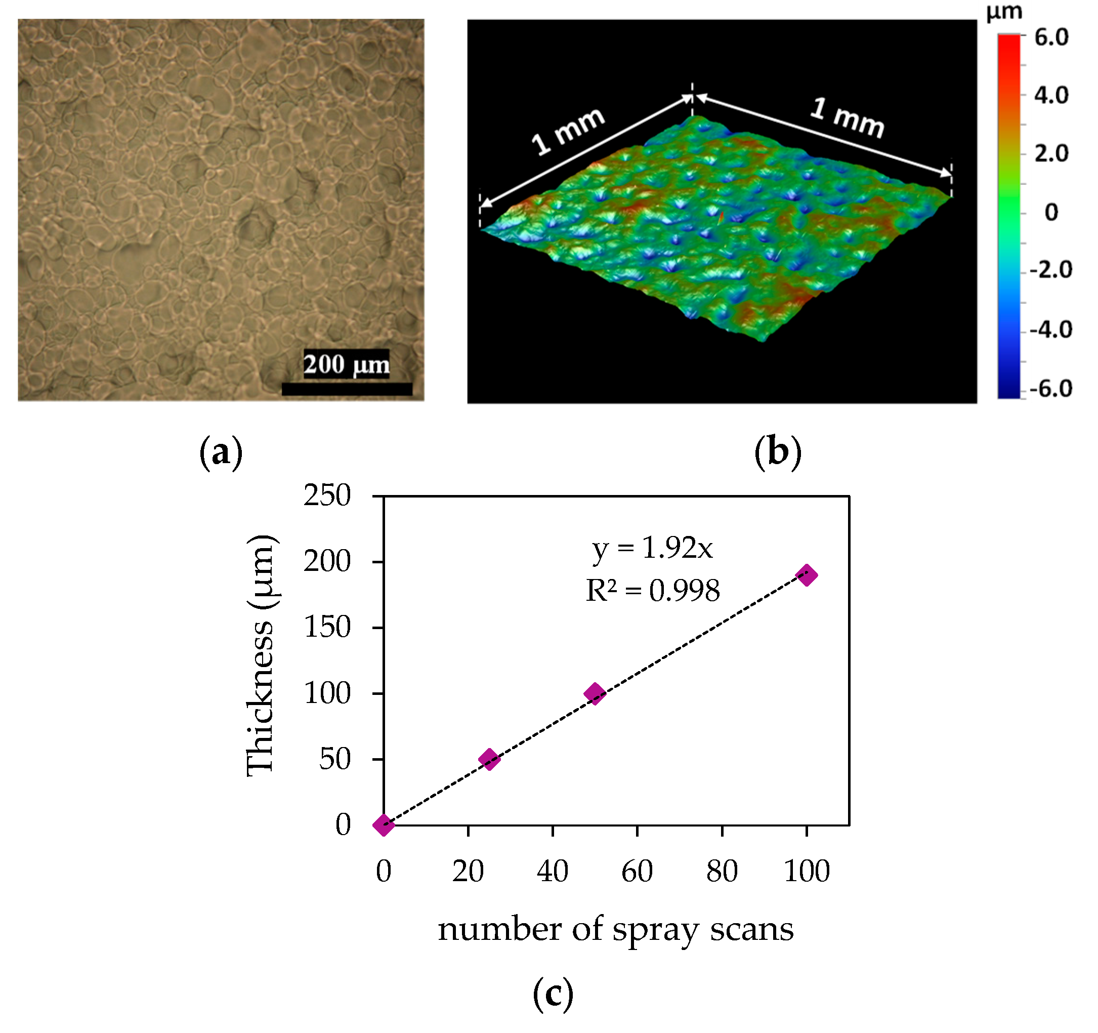
3.1. SIBSTAR Film Characterization

Figure 2a shows the top view optical micrograph of a SIBSTAR film made of 50 spray coats (100 µm thick) deposited on a glass slide. It shows the film consists of randomly distributed droplets deposited one on top of the other, which is typical for spray-coated films [26]. This is the result of the fast drying SIBSTAR solution droplets before they re-dissolve the layer underneath. The 3D mapping of the surface of the same SIBSTAR film is shown in Figure 2b, which demonstrates a root mean square (RMS) roughness and peak to valley (P–V) values of 1.4 µm and 12 µm, respectively. Neither porosity nor pinholes were observed in the samples through their surface optical microscopy and 3D mapping. Figure 2c shows the thickness of the deposited SIBSTAR film, measured at the center of the substrate, versus the number of spray coats. There is a linear relationship between the two, with a deposition rate of 1.92 µm per coat.
Tensile Young’s modulus of spray-coated SIBSTAR film was measured to be (11.2 ± 0.5) MPa (stress-strain curves provided in Appendix B). This value is 4 to 10 times larger than the values reported for cast films at a strain of 100% [27]. While the difference can partially be due to the difference in the fabrication process, it has been shown that Young’s modulus of SIBSTAR varies with the magnitude of the applied strain and is larger at smaller values [27]. The obtained value in this work is in accordance with the value reported by Naficy et al. [1].
Water and PC absorbances of SIBSTAR spray-coated films were measured by immersing 190-µm thick SIBSTAR films with areas of 1 cm × 2 cm (equivalent mass of (34.6 ± 0.3) mg) in each of the liquids. No measurable mass change (<0.1% or <38 µg/cm2) was observed for the SIBSTAR film immersed in deionized (DI) water after two weeks, while the mass of the one immersed in PC increased by 0.5 mg (~1.4% or 190 µg/cm2). After seven months, the film immersed in DI water absorbed 0.4 mg water (equivalent mass increase by ~1.15% or 152 µg/cm2) and the one in PC absorbed a further 0.6 mg of PC (equivalent total mass increase by 3.2% or 418 µg/cm2). This demonstrated the resistance of SIBSTAR toward absorbing water or propylene carbonate, which makes it a proper barrier to protect devices when operating in water.

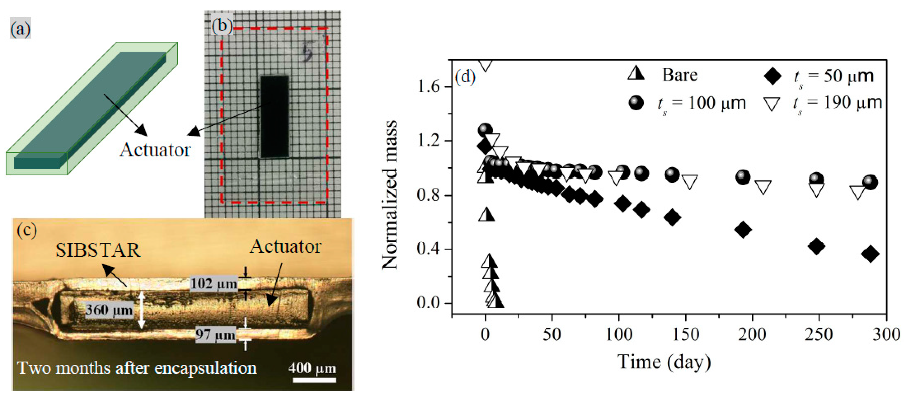
3.2. Characterization of Permeant Mass Transfer in SIBSTAR Sprayed Films

As discussed in Section 1, SIBSTAR is a good candidate as an encapsulating material for ionic bending actuators. In this case, we demonstrate how well sprayed films of SIBSTAR at different thicknesses can protect the propylene carbonate stored in tri-layers from being evaporated.
Figure 3a shows the schematic of an encapsulated tri-layer. Figure 3b shows a top view optical image of a 4 mm × 12 mm trilayer encapsulated with ~100 µm thick SIBSTAR films. The encapsulation’s margin is indicated with red dashed lines. The encapsulation extension is provided in all the samples to ease holding and handling of the devices. The cross-section optical micrograph of a tri-layer (thickness of ~360 µm when it was freshly removed from the electrolyte [2]) encapsulated with ~100 µm thick SIBSTAR is demonstrated in Figure 3c (for this sample, the sides were covered with a thick solution of SIBSTAR using a fine brush). The measurement was performed two months after the encapsulation was carried out. It shows that, after two months, no significant change in the thickness of the tri-layer occurs if the device is encapsulated with a ~100-µm thick SIBSTAR film. We showed in our previous work that a similar tri-layer with no encapsulation loses ~40% of its initial mass of PC within one day. This mass loss shrinks the thickness of the device from ~360 µm to ~290 µm and significantly affects the intermittent and cycling performance of the tri-layer [2]. Clearly, the encapsulation is greatly slowing the mass loss.
The retained mass of propylene carbonate in three bare tri-layers (named as Si, where i = 1, 2, 3), and the retained sum of the masses of propylene carbonate and toluene in the encapsulated tri-layers, were measured over time. The encapsulated tri-layers were named as Si with 50 µm (i = 4, 5, 6), 100 µm (i = 7, 8, 9), and 190 µm (i = 10, 11, 12) thick spray-coated SIBSTAR encapsulations. All the measurements were done in a CTH room at (23 ± 2) ˚C and (50 ± 3)% RH. The corresponding results are demonstrated in Appendix C. Among those, samples S3, with no encapsulation, and S5, S8, and S10 with 50-µm, 100-µm, and 190-µm thick SIBSTAR encapsulations, respectively, which show the least PC mass loss compared to those with the same encapsulating layer’s thickness, were selected since they demonstrate the best capability of SIBSTAR at different thicknesses in protecting the device from losing the stored PC. The results of their normalized mass loss over time are demonstrated and compared in Figure 3d. The normalizations were done relative to the initial mass of the propylene carbonate stored in the corresponding tri-layer (45% of the initial mass of the tri-layer [2]) to demonstrate the percentage of propylene carbonate retained over time after the toluene trapped in SIBSTAR shield is thoroughly evaporated. That is why the demonstrated graphs in Figure 3d for encapsulated tri-layers have initial values of more than 1. The observed initial sharp decay is due to the evaporation of trapped toluene from the corresponding encapsulating shield.
According to Figure 3d, while the total amount of PC stored in the tri-layer evaporates within several days, 36%, 88%, and 83% of the initial mass of PC is retained in the tri-layers after ~300 days if 50-µm, 100-µm, and 190-µm thick SIBSTAR encapsulation is applied, respectively. The process of diffusion of permeant molecules across a non-porous polymeric barrier follows Fick’s laws of diffusivity, since the driving force is the transmembrane permeant concentration difference [24]. Solving Fick’s equations for such a system, the mass transfer rate of permeant molecules (PC vapor molecules),   TR P C , n , through the thickness of the barrier, t s , over area, A s , which is linear at equilibrium, is described using Equation (1) [28]
TR P C , n = a P C t s A s .
a PC is the PC mass loss rate, and, for each sample, it is obtained from the slope of the linear region (R2 > 0.99) of the corresponding graph shown in Figure A2a–d (Appendix C) and the initial mass of propylene carbonate stored in the sample. The obtained TR P C , n is used as an index to describe how well the samples are encapsulated. The smaller its value is, the better the encapsulation is performing. The values of area (surface area, side area, and total area), initial mass of PC stored in the tri-layer, PC loss rate, and TR P C , n , along with the time to lose 20% of the stored PC and the operation lifetime (time to lose 86% of the stored PC [2]) of the tri-layers are summarized in Table 2. It shows that, for samples with 50-µm, 100-µm, and 190-µm thick SIBSTAR encapsulations, the measured values of TR P C , n sit within the range of 9.1 to 23.9 µg m m−2 day−1, 3.1 to 15.6 µg m m−2 day−1, and 9.9 to 29.6 µg m m−2 day−1, respectively. The wide range of TR P C , n values makes us suspect that the thickness of the encapsulating layer is not uniform or is not the same in all the six directions. It was shown in Figure 2b that SIBSTAR spray-coated film is uniform and its roughness and peak to valley values, being equal to 1.3 µm and 12 µm, respectively, are well below the thickness of the encapsulating layers (>50 µm). As mentioned before, spray-coating is not conformal and the sides of the tri-layers, being relatively perpendicular to the direction of the spray, cannot be well coated along with their surfaces. To compensate that, we tilted the samples and spray coated the sides separately. However, we could not evaluate the thickness of the encapsulation in those areas. The area of the sides represents 8.2% to 10.7% of the total area of the tri-layer, which is not negligible and, if the thickness of the encapsulating layer at those areas is smaller than its intended thickness (that of the two surfaces), the sides can have a significant impact on letting the propylene carbonate escape from the tri-layer faster. Hence, the variation in the values of TR P C , n obtained for different samples may, possibly, be explained by that.
We showed in our previous work that, for a bare tri-layer actuating intermittently in air, the time constant of the device increases by 10% after losing 20% of its initial PC mass [2]. This is accompanied by a 20% increase in its maximum curvature. According to Figure 3d, this mass loss takes less than half a day if the bare tri-layer is stored in a CTH room at (23 ± 2) ˚C and (50 ± 3)% RH. If a 50-µm thick encapsulation is applied to the device, this time can delay to more than 65 days (~120 times improvement), in the same measurement condition. This further improves if the encapsulation gets thicker to 100 µm, as more than 500 days (nearly a year and a half, equivalent of more than 1000 times improvement) is estimated to be needed to lose 20% of the stored PC in the device. According to Equation (1), this improvement was expected to further increase by increasing the thickness of the encapsulating layer to 190 µm. However, the results show that 20% of PC mass loss takes place after nearly 330 days (~ 11 months). This, as explained before, is probably due to the thinner encapsulation on the sides, which let PC escape more easily from the sample.
According to the results obtained for these tri-layer actuators in our previous work [2], the device is still operational after losing 86% of the initial mass of PC stored in it. While, for a bare tri-layer, the operation lifetime is only four days, for tri-layers encapsulated with 50 µm, 100 µm, and 190 µm thick spray-coated SIBSTAR films this time are estimated to be able to delay to 390 days (over a year or ~100 times improvement), ~2400 days (6.5 years or 600 times improvement), and ~1400 days (nearly four years or 450 times improvement), respectively. This significant improvement in the operation lifetime of the device is well beyond what has been reported previously.
The variation in the results obtained for different samples with the same thickness of the encapsulating layer, and also comparing the results of those with different thicknesses of encapsulation, makes us reluctant to report a unique value of TR P C , n for SIBSTAR. However, the obtained results demonstrate the capability of this material as an encapsulating layer.

3.3. Effect of Encapsulation on the Extent to Which the Trilayer Can Bend

To investigate the effect of the encapsulating layer on the extent of bending of the tri-layers, a square wave voltage with an amplitude of ±2 V and period of 20 s (half period being ~5 times larger than the time constant of the device) was applied to devices before and after encapsulation and their curvatures were compared. Figure 4 shows top-view optical images of the peak to peak maximum bending of a tri-layer with (a) no encapsulation, and tri-layers with SIBSTAR encapsulations with thicknesses of (b) 50 µm, (c) 100 µm, and (d) 190 µm. The curvatures of the beams were calculated by fitting circles to the images of the actuated tri-layers. It shows that, when a 50-µm thick SIBSTAR encapsulation is applied to the tri-layer, its curvature decreases from (0.72 ± 0.02) cm−1 to (0.40 ± 0.02) cm−1 (~55% of the curvature before encapsulation). As the thickness of the encapsulating layer further increases to 100 µm and 190 µm, the curvature of the tri-layer further decreases to (0.32 ± 0.02) cm−1 and (0.21 ± 0.02) cm−1, which corresponds to ~44% and ~30% of the curvature of the tri-layer before encapsulation, respectively. As discussed in Appendix A, the decrease in the curvature of the device is due to the added encapsulating layer on the two surfaces as well as the two walls of the tri-layer actuator, which bend along with the device.

3.4. Effect of Encapsulation on the Cycling Response of Tri-Layer Actuators in Flowing Air

To investigate the effect of encapsulation on the lifecycle of a tri-layer conducting polymer actuator operating in air, a square wave voltage with amplitude of ±2 V and period of 2 seconds (frequency of 0.5 Hz), was applied to bare and encapsulated tri-layers (ts = 100 µm) and their displacements were measured over time, using a laser displacement sensor. An electric fan was used to facilitate the evaporation of the solvent from the device. Figure 5 shows the normalized displacement,   D   = half of the peak to peak displacement, and the peak current, i 0 , (= half of the peak to peak current) passing through the tri-layers with no encapsulation and with 100-µm thick SIBSTAR encapsulation, cycling in flowing air. The top x-axis shows the number of cycles. The normalizations were done relative to the initial values, which are indicated in the corresponding graph. In all figures, the graphs in grey show the actual values of the normalized quantity (current or displacement) and the black lines (dashed line for displacement and solid line for current) demonstrate the corresponding smoothened values.
As shown in Figure 5a, the displacements of the bare tri-layer operating in flowing air decrease as soon as the actuation starts. The initial rate of displacement decay is 55 %/h, which decreases over time and, after 3 h (5.4 × 10³ cycles), when only ~20% of the initial displacement is retained, drops down to ~9 %/h. We showed in our previous work that the displacement of a cycling actuator follows the current passing through it, which is also observed in Figure 5b [2]. As the tri-layer actuator cycles in air, the stored PC in it evaporates and causes the viscosity of the electrolyte to increase and, hence, its ionic conductivity to decrease. This explains the observed decrease of the peak current passing through the bare tri-layers operating in flowing air and, hence, the decrease of the tri-layer’s displacement, as shown in Figure 5a,b, respectively.
For the tri-layer encapsulated with a 100-µm thick film of SIBSTAR, as shown in Figure 5c, the decay rate of displacement is initially ~13 %/h and, after ~3 h of actuation in flowing air (5.4 × 10³ cycles at 0.5 Hz), when 85% of the displacement is retained, drops down to less than 2 %/h. The normalized peak current passing through the encapsulated tri-layers is demonstrated in Figure 5d, which shows it decreases with a relatively constant decay rate of ~2 %/h and, after 3 h of actuation in flowing air (5.4 × 10³ cycles at 0.5 Hz), ~94% of the peak current passing through the tri-layer, is retained. The small decline in the current passing through the device, which is likely due to the evaporation of PC at regions where the device is clamped, suggests the excellent encapsulation of SIBSTAR, which has also been shown in Figure 3b,c. Further work may be warranted to explore the best methods to make electrical contact through the encapsulation. Comparing the current and displacement graphs of the encapsulated tri-layer actuating in flowing air, shows that the rate at which the displacement decays is initially larger than that of the current (13.5%/h for displacement versus 2%/h for current). The larger initial decay rate of displacement in the encapsulated tri-layer actuator, compared to that of the peak current passing through the device, might be due to the change in the mechanical properties of SIBSTAR as the device cycles. This, however, requires further investigations to validate and to find ways to control it if the device is required to continuously cycle for hours.

4. Conclusions

Uniformly thick SIBSTAR films with Young’s moduli of ~11 MPa were obtained through a spray-coating technique. We showed in this work that, by using spray-coated SIBSTAR films as encapsulating layers, the storage lifetime of PEDOT/PEO:NBR/PEDOT tri-layer actuators significantly increases by protecting the device from getting dry in air over time. Additionally, 20% of propylene carbonate in a bare tri-layer evaporates after less than half a day if it is stored in a controlled temperature and humidity (CTH) room at (23 ± 2) ˚C and (50 ± 3)% RH. This time can be extended to more than two months (~240 times improvement) and 18 months (>1000 improvement) if 50-µm and 100-µm thick spray-coated SIBSTAR are applied to the device, respectively. This is at the expense of losing the extent of bending of the tri-layer due to the added layers, which cause the flexural rigidity of the tri-layer beam to increase.
The strong capability of spray-coated SIBSTAR films toward protecting conducting polymer actuators from losing their solvent or even the whole electrolyte as they are stored/operated in air or in DI water, respectively, along with their low Young’s modulus (~11 MPa) and ease of fabrication, makes them a promising material to protect other ionic devices such as IPMCs [3,4], bucky gel actuators [15], flexible batteries [29], supercapacitors [7], and ionic-electrode capacitive sensors [5]. Moreover, applying medical grade SIBS coatings on ionic devices can also expand their applications toward in vivo and implantable devices.

Author Contributions

Conceptualization, S.E.T. and J.D.W.M. Methodology, S.E.T. and J.D.W.M. Investigation, S.E.T., A.F., C.P., and G.T.M.N.; resources, J.D.W.M., F.V. Writing—original draft preparation, S.E.T. Writing—review and editing, S.E.T. and J.D.W.M. Visualization, S.E.T. Supervision, J.D.W.M. and F.V. C.P. and G.T.M.N. Project administration, J.D.W.M. Funding acquisition, J.D.W.M. and F.V.

Funding

The Natural Sciences and Engineering Research Council of Canada (NSERC) through a Discovery and a CRD grant supported this work.

Acknowledgments

This work made use of the 4D LABS shared facilities supported by the Canada Foundation for Innovation (CFI), British Columbia Knowledge Development Fund (BCKDF), Western Economic Diversification Canada (WD), and Simon Fraser University (SFU).

Conflicts of Interest

The authors declare no conflict of interest.

Appendix A

The flexural stiffness of a beam is obtained through the familiar equation, K T = 3 ( E I ) b / L 3 , where L is the length of the beam and EI is its flexural rigidity and is obtained through Equations (A1) for an encapsulated beam (including three layers).
( E I ) b = W 12 ( E e ( h T 3 h t 3 ) + E t h t 3 ) + t s 6 E e h T 3 ,
where E e and E t represent the Young’s moduli of the encapspulating layer and the beam, respectively. W is the width of the beam, h T = 2 t s + h t , is the total thickness of the encapsulated beam, and t s and h t are the thicknesses of the encapsulating layer and the beam, respectively. According to Equation (A1), the smaller the Young’s modulus and the thickness of the encapsulating layer are, the less impact they have on the flexural rigidity and, hence, the flexural stiffness of the beam ( = W E t h t 3 / 4 L 3 ) before encapsulation. In the case where h t >> t s and W >> t s , the fractional stiffness added by the encapsulating layer is shown below.
Δ K E K T W 4 L 3 ( 6 E e h t 2 t s ) W 4 L 3 E T h t 3 = 6 E e t s E T h t .
Therefore, clearly, the product of the encapsulating layer’s modulus and its thickness needs to be minimized.
The mass transfer rate across a polymeric film, a , is inversely related to its thickness, t s , through Equation (A3) [24], which is analogues to Equation (1).
a = V T R n   A t s   ,
where A is the area over which the permeant transfers across and VTRn is the permeant-vapor transmission rate of the polymer for its unit thickness and depends on various properties of the polymer material such as its saturation level, the degree of crosslinking, crystallinity, glass transition temperature, and molecular weight, as well as the nature of the penetrant [24]. Equation (A3) suggests a thicker film of polymer can compensate for a large vapor transmission rate, but this conflicts with the requirement for the flexural stiffness. Combining the requirements for minimum change on the flexural stiffness as the encapsulation film is applied with minimum transmission rate through it, we introduce a figure of merit for polymeric materials,   γ = V T R n E e , which is ideally small, so the film provides a proper encapsulation with low impact on the flexural stiffness of the structure.

Appendix B

Stress-stress curve of a SIBSTAR film (10 mm × 4 mm × 0.1 mm) is shown in Figure A1. The measurement was carried out for 10 cycles at 0.1 Hz.
Figure A1. Stress-strain curve for SIBSTAR film with length, width, and thickness of 10 mm, 4 mm, and 100 µm, respectively.
Robotics 08 00060 g0a1

Appendix C

Figure A2a demonstrates the retained normalized mass of propylene carbonate over time in three bare tri-layers named as Si, where i = 1, 2, 3. The normalizations were done relative to the initial mass of propylene carbonate stored in each of the tri-layers (45% of the initial mass of the tri-layer [2]).
Figure A2b–d show the retained total mass of propylene carbonate and toluene in encapsulated tri-layers over nearly 300 days. These are named as Si with 50 µm (I = 4, 5, 6), 100 µm (I = 7, 8, 9), and 190 µm (I = 10, 11, 12) thick spray-coated SIBSTAR encapsulations. Similar to the bare tri-layers, the measurements were done in a CTH room at (23 ± 2) ˚C and (50 ± 3)% RH. All the normalizations were done relative to the initial mass of the propylene carbonate stored in the corresponding tri-layer (45% of the initial mass of the tri-layer [2]) to demonstrate the percentage of propylene carbonate retained over time after the toluene in the SIBSTAR shield is thoroughly evaporated.
Figure A2. (a) Normalized mass of propylene carbonate (PC) stored in tri-layers with no encapsulation over time. Normalized mass of propylene carbonate stored in tri-layers plus toluene trapped in the corresponding SIBSTAR encapsulation shields with thicknesses of (b) ts = 50 µm, (c) ts = 100 µm, and (d) ts = 190 µm over time. All the normalizations were done relative to the corresponding initial mass of propylene carbonate stored in each tri-layer.
Robotics 08 00060 g0a2

References

  1. Naficy, S.; Stoboi, N.; Whitten, P.G.; Spinks, G.M.; Wallace, G.G. Evaluation of encapsulating coatings on the performance of polypyrrole actuators. Smart Mater. Struct. 2013, 22, 075005. [Google Scholar] [CrossRef]
  2. Takalloo, S.E.; Fannir, A.; Nguyen, G.T.M.; Plesse, C.; Vidal, F.; Madden, J.D.W. Evaluating performance of wet unencapsulated PEDOT trilayer actuators operating in air and water. Multifunct. Mater. 2019, 2, 014003. [Google Scholar] [CrossRef]
  3. Kim, S.J.; Lee, I.T.; Lee, H.-Y.; Kim, Y.H. Performance improvement of an ionic polymer–metal composite actuator by parylene thin film coating. Smart Mater. Struct. 2006, 15, 1540–1546. [Google Scholar] [CrossRef]
  4. Lei, H.; Li, W.; Tan, X. Encapsulation of ionic polymer-metal composite (IPMC) sensors with thick parylene: Fabrication process and characterization results. Sens. Actuators A 2014, 217, 1–12. [Google Scholar] [CrossRef]
  5. Sarwar, M.S.; Dobashi, Y.; Preston, C.; Wyss, J.K.M.; Mirabbasi, S.; Madden, J.D.W. Bend, stretch, and touch: Locating a finger on an actively deformed transparent sensor array. Sci. Adv. 2017, 3, e1602200. [Google Scholar] [CrossRef] [PubMed]
  6. Park, K.-S.; Schougaard, S.B.; Goodenough, J.B. Conducting-Polymer/Iron-Redox- Couple Composite Cathodes for Lithium Secondary Batteries. Adv. Mater. 2007, 19, 848–851. [Google Scholar] [CrossRef]
  7. Mirvakili, S.M.; Hunter, I.W. Vertically Aligned Niobium Nanowire Arrays for Fast-Charging Micro-Supercapacitors. Adv. Mater. 2017, 29, 1700671. [Google Scholar] [CrossRef] [PubMed]
  8. Somani, P.; Mandale, A.B.; Radhakrishnan, S. Study and development of conducting polymer-based electrochromic display devices. Acta Mater. 2000, 48, 2859–2871. [Google Scholar] [CrossRef]
  9. Rivnay, J.; Inal, S.; Salleo, A.; Owens, R.M.; Berggren, M.; Malliaras, G.G. Organic electrochemical transistors. Nat. Rev. Mater. 2018, 3, 17086. [Google Scholar] [CrossRef]
  10. Hallett, J.P.; Welton, T. Room-Temperature Ionic Liquids: Solvents for Synthesis and Catalysis. 2. Chem. Rev. 2011, 111, 3508–3576. [Google Scholar] [CrossRef] [PubMed]
  11. Jaakson, P.; Aabloo, A.; Tamm, T. Encapsulation of Ionic Electroactive Polymers: Reducing the Interaction with Environment; Bar-Cohen, Y., Vidal, F., Eds.; International Society for Optics and Photonics: Las Vegas, NV, USA, 2016. [Google Scholar]
  12. Shoa, T.; Madden, J.D.; Fekri, N.; Munce, N.R.; Yang, V.X.D. Conducting polymer based active catheter for minimally invasive interventions inside arteries. In Proceedings of the 2008 30th Annual International Conference of the IEEE Engineering in Medicine and Biology Society, Vancouver, BC, USA, 20–24 August 2008; pp. 2063–2066. [Google Scholar]
  13. Smela, E. Conjugated Polymer Actuators for Biomedical Applications. Adv. Mater. 2003, 15, 481–494. [Google Scholar] [CrossRef]
  14. Ebrahimi Takalloo, S.; Seifi, H.; Madden, J.D.W. Design of Ultra-Thin High Frequency Trilayer Conducting Polymer Micro-Actuators for Tactile Feedback Interfaces; Bar-Cohen, Y., Ed.; International Society for Optics and Photonics: Portland, OR, USA, 2017. [Google Scholar]
  15. Fukushima, T.; Asaka, K.; Kosaka, A.; Aida, T. Fully Plastic Actuator through Layer-by-Layer Casting with Ionic-Liquid-Based Bucky Gel. Angew. Chem. Int. Ed. 2005, 44, 2410–2413. [Google Scholar] [CrossRef] [PubMed]
  16. Woishnis, W. Permeability and other Film Properties of Plastics and Elastomers; Plastics Design Library: Norwich, NY, USA, 1995; ISBN 978-1-884207-14-3. [Google Scholar]
  17. Crompton, T.R. Mechanical Properties of Polymers. In Physical Testing of Plastics; Smithers Rapra: Shrewsbury, UK, 2012. [Google Scholar]
  18. Noda, K.; Kimura, K.; Fukuda, R.; Tawada, M. Performance Characterization of Styrene-Isobutylene Block Copolymer; Thermoplastic Elastomers: Munich, Germany, 2006. [Google Scholar]
  19. Pinchuk, L.; Wilson, G.J.; Barry, J.J.; Schoephoerster, R.T.; Parel, J.-M.; Kennedy, J.P. Medical applications of poly(styrene-block-isobutylene-block-styrene) (“SIBS”). Biomaterials 2008, 29, 448–460. [Google Scholar] [CrossRef] [PubMed]
  20. TAXUS™ Liberté™ Paclitaxel-Eluting Coronary Stent System. Available online: http://www.bostonscientific.com/en-US/products/stents--coronary/taxus-liberte-coronary-stent-system.html (accessed on 23 May 2019).
  21. Kamath, K.R.; Barry, J.J.; Miller, K.M. The TaxusTM drug-eluting stent: A new paradigm in controlled drug delivery. Adv. Drug Deliv. Rev. 2006, 58, 412–436. [Google Scholar] [CrossRef] [PubMed]
  22. Pinchuk, L.; Riss, I.; Batlle, J.F.; Kato, Y.P.; Martin, J.B.; Arrieta, E.; Palmberg, P.; Parrish, R.K.; Weber, B.A.; Kwon, Y.; et al. The development of a micro-shunt made from poly(styrene- block -isobutylene- block -styrene) to treat glaucoma: SIBS-BASED INNFOCUS MICROSHUNT®. J. Biomed. Mater. Res. Part B 2017, 105, 211–221. [Google Scholar] [CrossRef] [PubMed]
  23. Gallocher, S.L.; Aguirre, A.F.; Kasyanov, V.; Pinchuk, L.; Schoephoerster, R.T. A novel polymer for potential use in a trileaflet heart valve. J. Biomed. Mater. Res. Part B 2006, 79B, 325–334. [Google Scholar] [CrossRef] [PubMed]
  24. George, S.C.; Thomas, S. Transport phenomena through polymeric systems. Prog. Polym. Sci. 2001, 26, 985–1017. [Google Scholar] [CrossRef]
  25. Ebrahimi Takalloo, S. Actualizing Fast Conducting Polymer Actuators: Design Optimization, Fabrication, and Encapsulation. Ph.D. Thesis, University of British Columbia, Vancouver, BC, Canada, 2019. [Google Scholar]
  26. Girotto, C.; Rand, B.P.; Genoe, J.; Heremans, P. Exploring spray coating as a deposition technique for the fabrication of solution-processed solar cells. Sol. Energy Mater. Sol. Cells 2009, 93, 454–458. [Google Scholar] [CrossRef]
  27. Perevosnik, K.A. Investigation pf the Mechanical and Thermal Properties of poly(styrene-block-isobutylene-block-styrene) (SIBS) and Its Blends with thymine-functionalized Polystyrene. Ph.D. Thesis, University of Akron, Akron, OH, USA, 2008. [Google Scholar]
  28. Daynes, H.A. The Process of Diffusion through a Rubber Membrane. Proc. R. Soc. Lond. Ser. A 1920, 97, 286–307. [Google Scholar] [CrossRef]
  29. Chen, Z.; To, J.W.F.; Wang, C.; Lu, Z.; Liu, N.; Chortos, A.; Pan, L.; Wei, F.; Cui, Y.; Bao, Z. A Three-Dimensionally Interconnected Carbon Nanotube–Conducting Polymer Hydrogel Network for High-Performance Flexible Battery Electrodes. Adv. Energy Mater. 2014, 4, 1400207. [Google Scholar] [CrossRef]
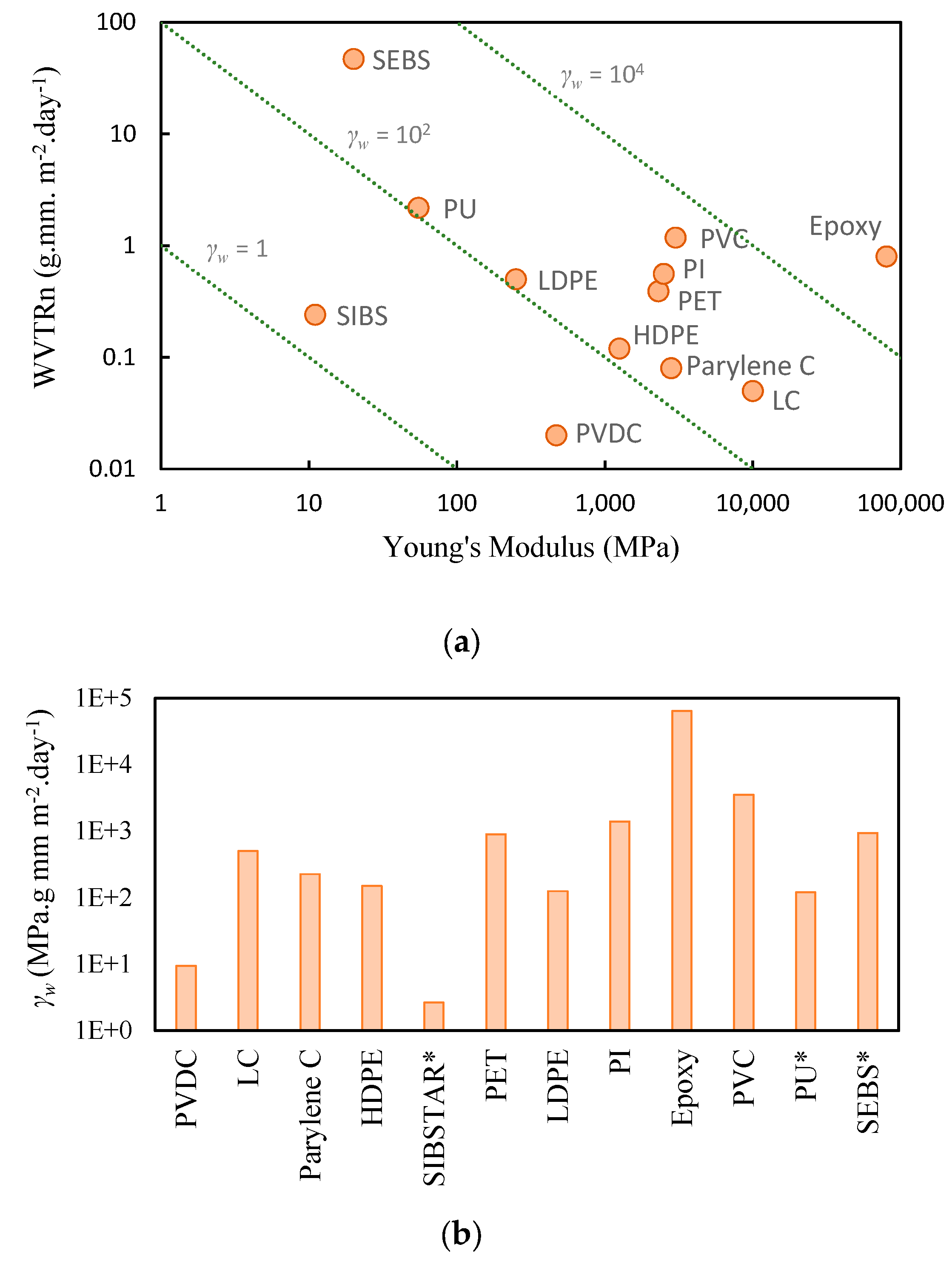
Figure 1. (a) WVTRn versus Young’s modulus of commonly used polymeric barriers. It suggests the closer the barrier sits to the bottom left corner of the graph (lower Young’s modulus and lower WVTRn), the better encapsulation performance can provide for the actuator. The dotted lines demonstrate constant values of the permeability modulus product, γ w , as indicated. (b) Comparison of γ w value shows that SIBSTAR has the best combination of compliance and low permeability among the studied encapsulating materials. (WVTRn increases from left to right). Those tagged with a * are elastomers at room temperature.
Robotics 08 00060 g001
Figure 2. (a) Top view optical micrograph and (b) 3D surface mapping of SIBSTAR films made of 50 spray coats (~100 µm) deposited on a glass slide and (c) SIBSTAR film’s thickness at the center of the glass slide substrate versus the number of scans. Thickness linearly increases as the number of spraying coats increases.
Robotics 08 00060 g002
Figure 3. (a) Schematic structure of an encapsulated tri-layer actuator, (b) top view optical image of an as-prepared encapsulated PEDOT/ PEO:NBR/PEDOT tri-layer actuator. The red dashed line shows the encapsulation margin, (c) cross section optical micrograph of an encapsulated PEDOT/PEO:NBR/PEDOT tri-layer actuator after two months of encapsulation with 100-µm thick SIBSTAR, and (d) comparison of the normalized mass decay over time of propylene carbonate stored in a tri-layer with no encapsulation and tri-layers with encapsulation thicknesses of ts = 50 µm, 100 µm, and 190 µm. All the normalizations are relative to the initial mass of the PC.
Robotics 08 00060 g003
Figure 4. Maximum bending of tri-layers with (a) no encapsulation, (b) 50-µm, (c) 100-µm, and (d) 190-µm thick SIBSTAR encapsulating layers. The dimensions of the tri-layers before encapsulation are L × W × ht = 10 mm × 2 mm × 0.36 mm. Images are overlaid to show the full extent of deflection after voltages of +2 V and −2 V are applied to each for 10 s.
Robotics 08 00060 g004
Figure 5. Normalized peak to peak (a) displacement and (b) current of a bare tri-layer and (c) displacement and (d) current of an encapsulated tri-layer with 100-µm thick SIBSTAR, cycling in air. The dimensions of both tri-layers are L × W × ht = 10 mm × 2 mm × 0.36 mm and the distance of the laser beam from the base of the tri-layer is (8 ± 0.5) mm. D0 and i00 are the initial values of the measured displacement and the peak current passing through the corresponding tri-layer, respectively. The graphs in grey show the peak-to-peak current variation through time while the black lines represent the smooth ones.
Robotics 08 00060 g005
Table 1. Typical material properties of common polymeric barriers. WVTRn values were measured at 37 °C to 40 °C and 90% RH [16,17,18].
Material’s NameAbbreviation or Trade NameYoung’s ModulusStrain at Yield or Fracture StrainWVTRn γ w
(MPa)(%)(g mm m−2 day−1)(MPa g mm m−2 day−1)
poly(styrene-b-isobutylene-b-styrene)SIBSTAR 103T 111.2 27000.242.7
poly(styrene-b-ethylene-butylene-b-styrene)SEBS, Kraton G270112080047940
PolyurethanePU 1557002.2120
Low-density PolyethyleneLDPE250190.5125
Polyvinylidene ChloridePVDC, Saran 56047050.029.4
High-density PolyethyleneHDPE1250150.12150
Polyethylene terephthalatePET23003.50.39900
PolyimidePI, Upilex R250040.561400
Poly(p-xylylene)- type CParylene C280020.08225
Polyvinyl chloridePVC30003.51.183540
Liquid CrystalLC, Vectra A9501000020.05500
PolyepoxidesEpoxy800001.30.864,000
1 Elastomers at room temperature. 2 Obtained in this work.
Table 2. Summary of the properties of the tri-layers and the corresponding encapsulating layer’s performance.
SampleEncapsulating Layer’s ThicknessTri-Layer’sInitial PC MassPC Mass Decay Rate ( a P C ) Normalized   PC   Transmission   Rate   ( T R P C , n ) Time to Lose 20% of Stored PCOperation Lifetime
Surface AreaSide AreaTotal Area
(µm)(mm2)(mg)(µg/day)(µg m m−2 day−1)(days)(days)
S10144.412.5156.913.7--0.54
S2150.313163.314.2--0.54
S3161.813.8175.615.6--0.54
S45094.510.2104.78.8199.165390 *
S59610.2106.28.920.39.665370 *
S69610.2106.4950.523.935300
S71009611.5107.58.816.215.6110460 *
S812012.2132.21143.1550 *2350 *
S910011.7111.78.94.64.4390 *1650 *
S1019012613.3139.310.56.49.9330 *1400 *
S111121312510.4519.129.680460 *
S1216514.8179.814.2517.420.3180700 *
Values tagged with a * were estimated, by assuming the mass loss stays linear.

