A Node-Based Method for SLAM Navigation in Self-Similar Underwater Environments: A Case Study

1
Instituto Argentino de Oceanografía—Consejo Nacional de Investigaciones Científicas y Técnicas (IADO-CONICET), Florida 8000, Bahía Blanca, Argentina
2
Departamento de Ingeniería Eléctrica y de Computadoras—(DIEC-UNS), Avenida Alem 1253, Bahía Blanca, Argentina
*
Author to whom correspondence should be addressed.
†
These authors contributed equally to this work.
Robotics 2017, 6(4), 29; https://doi.org/10.3390/robotics6040029
Submission received: 30 June 2017
/
Revised: 19 October 2017
/
Accepted: 20 October 2017
/
Published: 31 October 2017
Abstract
:This work deals with the development of a node-based monocular visual methodology for autonomous vehicle navigation which has the goal of exploring unknown regions of the sea bottom with a posterior safe revisiting of them. The work accentuates characteristics of the seabed like self-similarity and backscattering. In a stepwise fashion, a visual guidance system constructs a shape similar to a narrow corridor by optimally creating a heading function on the basis of keypoints threads, which ensures future revisits. The corridor is composed of nodes and paths in between. Each path is composed of a visual-odometry-based trail which is generated in feature-poor environments, in combination with a feature-based trail which emerges in feature-rich regions. A probabilistic analysis of the uncertainties and their impact in the success rate on loop closings is carried out. We work out two case studies, the first employing an ad-hoc benchmark and the second a series of experiments in the real world. From here qualitative conclusions can be drawn out that enable us to anticipate potential applications of the approach in the field of autonomous navigation underwater.
1. Introduction
Important applications in computer vision and autonomous robotics deal with the processing and understanding of video moving scenes. Particularly, sequential images captured by a monocular camera attached in the frontal part of a vehicle helps it to make decisions for autonomous navigation. This area has a wide significance for many problems in robotics such as SLAM (Simultaneous Localization and Mapping), target tracking, vision-based control, 3D-view mapping and place recognition (see general state-of-the-art references such as [1,2,3]). Even when the SLAM problem is stated in a complete and general form, particular problems in the exploration of unknown environments are not sufficiently dealt with, above all regarding the wide diversity of applications in subaquatic robotics and the tough accessibility to the oceanic world.
In this work we focus on our general interest in subaquatic environments and self-contained, intelligent and decision-making AUVs (Autonomous Underwater Vehicles), employing near-seafloor imagery. More precisely, we will focus the exploration of unknown regions. The underlaying context for this work is the vision-based navigation underwater founded on SLAM techniques. A particular point of concern in this framework is the monocular vision in underwater environments (see [4] for a global scope of the technique for this issue).
While the great involvement in SLAM embraces applications in the aerial and terrestrial context, the magnitude of subaquatic applications is far less. However, due to the large relevance of the sea in human activities, it is a matter of time for that to turn it around.
In typical applications in open air, SLAM methods can recognize places and objects seamlessly from numerous features and, to some extent, from different viewpoints. In contrast in subaquatic applications, this issue will demand a huge care with respect to many aspects, among them security, robustness and long-term performance [3]. Clearly all these aspects point out the success of an autonomous vehicle to return by its own means to the source after a mission is concluded, among other things.
Assuming a navigation underwater at certain altitude over the sea bottom, regular elements and topological characteristics of the sea floor may require both a planar and three-dimensional metrics. Additionally, dynamic elements like benthos and marine wildlife may change the landscape physiognomy in the short and long term alike [5]. Moreover, in shallow waters, the presence of sunlight caustic waves on the floor causes a large perturbation of the footage [6,7]. In this sense, the backscattering and mesopic conditions of lighting levels may reduce visibility drastically. Additionally, occlusions, although to a lesser degree in subaquatic environments, can hinder the tasks of camera tracking and mapping as well.
However, one of the most challenging problems in both outdoors and underwater applications is the self-similar appearance caused by visual patterns in relief and texture that approximately repeat in a monotonous way on the landscape [8]. This effect can potentially carry the risk of location failures, even when the presence of features is abundant. The map building in self-similar environments could combine advantageously visual feature comparison with statistic evidence collection as [9], however, this may be difficult underwater due to the wide variety of self-similar patterns.
The global motivation in this paper encompasses specific real problems in subaquatic navigation, namely, the exploration and safe return of an autonomous vehicle. Also, we ultimately strive to design a methodology for a vision-based autonomous system, whereby it is able to build and consolidate corridors on involved regions of the sea bottom.
The idea of a corridor is quite old, consider for instance the discovery of the American Continent by crossing the Atlantic Ocean, to and fro repeatedly with no reliable global instrumentation. A projection of this idea in SLAM can be found in the method “Teach & Repeat”, [10], for path following in unknown and inaccessible environments outdoors like a dense wood, or in the space exploration, on the surface of Mars. However, the method basics do not include autonomous exploration, rather, the first construction of the pathway is given remotely to a rover by a human operator with the aid of a vehicle camera on the front. Once an a-priori feasible trajectory is defined, the vehicle can “repeat” the path it was previously pointed to, and it is “taught”.
A variant of the basic idea employs active SLAM for exploring and building a map for posterior revisits (see recent works, [11,12,13]). Also, the exploration may be done in highly dynamic environments with moving obstacles and dynamic changes in localization demands. Finally, the authors claim the accuracy is better than a standard grid-map based approach while requiring orders of magnitudes less computation and memory resources.
Our start point in this work to the problem of researching unknown regions is different. First, we will solve the problem of exploration autonomously, unlike [10]. Thereafter, we will simultaneously search for the most robust way in the exploration, in the sense of maximizing the loop closures in revisitings and unlike the works in active SLAM. Our heuristics and techniques are different in nature and thought at first for subaquatic navigation.
One problem in such scenarios can be framed in sparse-feature environments wherein there exist two or more non-connected maps of the sea bottom, which were successfully built employing some proper mapping technique provided by SLAM. Moreover, the maps are locally valid and there does not exist any common coordinate system. Besides, one can figure there is a vast region among them, characterized by a soil with marked self-similarity in texture and relief. If the goal is the bridging of known zones by exploring a corridor, the SLAM-based exploration is not suitable. The reason is that it is quite probable that similar patterns with different locations are mismatched and identify as being the same pattern, the same position. This does not rely on the robustness of the feature descriptor, but rather in the property of self-similarity.
In broad outlines, the goal of this paper is to develop an effective approach for establishing mechanisms that can help a vision-based guidance system doing a primary but meaningful navigation across “unknown” regions, connecting other well-mapped regions by means of two-way corridors, or returning safely to the source point, all without the need of becoming aware of a consistent global self-position.
2. Objective
The sea soil we are interested in has, essentially, such features of texture and relief that a number of them can be distinguished from a certain distance and with some degree of robustness against a change of point of view. We will focus on usual elements spread randomly on a rather smooth surface, accounting for banks of sand and benthos, rock outcroppings, and furrows, among others. In addition, patterns with these characteristics may approximately repeat in many other sites of the seabed.
In broad outlines, the submarine landscape can be conceived as a structure of visual elements in an affine space, yet with reasonably small affine distortions. In principle, navigation by SLAM techniques may have serious problems to accomplish observation-feature correspondences in the submarine soil, first and foremost due to the similarity of usable and stationary keypoints. A consequence of this navigation will most likely be not only the loss of precision and robustness of pose estimations but also the complete failure of loop closures in revisiting phases.
The framework in this paper is not directly the submarine navigation in mapped areas to solve a global localization problem, instead we attempt to engineer a solution to connect consolidated SLAM-based maps separated by a vast sea floor, which is rather sparse in robust visual features. Another objective is the autonomous exploration by a submarine up to the “point of no return” of its energetic autonomy and to provide it the means to came back.
In this framework, we will present a method based on chained nodes which potentially will allow for autonomous navigation in unknown regions. A node is defined as a distinguishable cluster with abundant blobs or landmarks in the soil. The node chain is represented by a sequence of physical viewpoints from which the vehicle monocular camera generates footage during navigation.
We start from the premise that a point with known position and a vast underwater scenario are available and conjecture at once that is feasible to navigate, for the first time tentatively by exploration to discover a corridor with the intention stated in the objectives. It is understood that once a corridor is created, it can be employed thereafter straightforwardly under certain conditions, revisiting the nodes in the chain in an orderly fashion. This is the same as the argument that a sufficient number of robust identified keypoints in one way may be distinguished in the comeback.
3. Chained-Node-Based Guidance
3.1. Heuristics of the Approach
In this section, a heuristics to achieve the objective is worked out and then formalized in the proposed method.
First, we state a type of navigation wherein an underwater vehicle with a frontal monocular camera pointing obliquely to the seafloor, is aided by a vision-based guidance. This system must define the vehicle pathway in real time on the basis of identified features on the seabed. The tasks performed by the guidance system are accomplished within a sampling time or step, which is an integer multiple of the frame rate. We also conceive a step that can be variable according to the demanded computing power inboard.
In an exploration phase, there is no prevailing fixed direction. Instead, the vision system opts for an optimal course but exercises extreme caution that the next possible headings in the horizon have the aptitude to lead the vehicle to a zone that is rich in features. This methodology is repeated step by step according to two stages. The first stage accomplishes a guidance over a poor-featured soil, while the second stage defines a guidance over a rich-featured soil. These stages are applied alternatively. The length of any stretch will depend on the characteristics of the scene. The common situation during the vehicle navigation is that the amount of generated keypoints is variable in time, in view of the fact that the feature density along the path does change.
The navigation departs from some known point at the contour of the source zone underwater, say (see Figure 1). The vehicle follows a fixed course. Assuming there is no preferential direction, the first heading is set arbitrarily, for instance perpendicular to the source map contour. The navigation here is basically odometer-guided straight ahead up to an apparently real pose , which coincides with the instant that the system sights a zone with features. Actually, this occurs from the pose , which is unknown and commonly differs from due to the odometric drift.
The subsequent construction of the corridor is composed of course of changes which are the result of decisions reached by the guidance system. Facing an abundance or scarcity of keypoints, every internode path is formally composed of two stretches, see Figure 1 for details and employed terminology. The following will take the symbol description in the figure as reference to support a concise explanation of the heuristics below.
Let us described the path generation involving the node pairs n and .
The first stretch connects a node located at its reference point , with some upcoming point through a rather sparse-featured sea bottom, while the second stretch links with the next node over a rich-featured sea bottom. The point is the first viewpoint in the internode path from which one can sight a lot of robust keypoints. The reference node accounts for the last viewpoint of the stretch, from which a scene plenty of features is identified. It is worth noticing here that a viewpoint is a camera pose in a six-degree space.
The stretch between the extremes and is conformed by other many viewpoints, from which also rich-featured scenes are observed. We will select particular viewpoints of the stretch and associate each one with a keyframe. We define a keyframe as the frame of a viewpoint from which abundant robust features are registered, i.e., features that are observed over a long period up to the moment this keyframe is settled.
In the absence of reliable features, the first stretch involves an odometer-guided navigation straight ahead regarding , while the second stretch leverages the high stream of features to determine a series of viewpoints from up to that are able to be tracked in a revisiting phase. As in the first node of the chain, the odometry-determined pose of the camera viewpoint is only apparent, while the associated pose is the real one. Moreover, even when the arrival heading at might be the natural direction for the first path stretch, the guidance system can eventually decide upon another heading that points to a preferential zone, in which presumably there could be robust features.
The description so far corresponds to the generation of nodes in the exploration. The tracking of nodes in the chain is the main objective in the consolidation of the corridor. Here, we will also formally differentiate points and of the exploration phase from ones which are reached in a posterior revisiting; both are termed equally but they will have different coordinates. Thus, the points and are varying dynamically during the construction and employment of the corridor, although it is intended that all and , as well, lie in their own vicinities.
All in all, the key idea behind these heuristics is that the underwater vehicle can construct a chain of nodes between two distant non-connected regions by exploring the seabed and it can in future repeat the same pathway safely.
It is also intended that the vehicle can return along the same route if a sufficient number of keypoints can be identified from diametrically opposed viewpoints. The existence of potential occlusions in the landscape might hinder a feature matching in the reverse travel. Thereby, it is important to be able to rely on an appropriate strategy for such special cases in order to ensure the intended goal.
Finally we will quote the issue of vehicle recovering. This is a matter of extreme importance and is particularly complex underwater. Regarding the energy autonomy of the vehicle, one can extend the heuristics to an exploration mission up to the point of no return, from which the approach drives the vehicle safely to the source point.
3.2. Exploration Phase
According to the previously described heuristics, the node selection during the exploration is the most important and delicate task in this phase. The parameters of a node are: its pose and departure heading from it . Additionally, one has to identify the viewpoint in the internode lapse to be able to change the navigation mode from odometer-based steering to feature-based tracking and vice versa. Finally, the selection of keyframes from on until , is another task to be accomplished in this phase.
First, keypoints must be detected and then, with the aid of a suitable criterion of robustness, selected or discarded. With the employment of an efficient feature detector/descriptor like SURF (Speeded-Up Robust Features), a set of keypoints begins with the generation of a rich-featured environment when the vehicle moves away from a source point.
Usually, robust keypoints leave 2D long traces over the time when they are observed on a certain fixed period of time, here referred to as T. In contrast, physical points of the sea floor that are perturbed, for instance, by sunlight caustic waves generate short or intermittent trails. Thus, they are practically differentiable from one another by the life lengths of their trails.
Now, we focus on the keyframes that are defined within the second stretch in the internode. As a general rule, each keyframe is associated to many long trails that occur within the lapse between two keyframes. Let us describe a trail by its time function , where and are the start and end time points in the period , k is the reference of the particular keyframe in the internode, and are path coordinates of the trail and n is a node number in the chain. is the separation in time of two consecutive keyframes. As the environment is unknown, the best choice for is a unique fixed observation period for all nodes of the chain, for instance, we set .
Due to unavoidable spatio-temporal lighting perturbations on the seabed, it is expected that a fraction of the trails have a short duration, that is , while others a larger life, that is . Once the observation time is expired in the keyframe, we threshold the life lapses of each trail and group all long trails in a compact set.
To this goal, we can argue that the longer the trail the more robust will be the detection of the associated keypoint. In other words, for the targeted subaquatic environments, it is reasonable to expect that a robust keypoint should be readily tracked from any point of view around it within the period T.
So we define a threshold as
with being a real number between zero and one. A suitable value for results from the histogram of trail lengths of the keyframe by selecting a value over the median value. As noticed, this selection is keyframe dependent.
Thus, the compact set of keypoints for the keyframe emerges from the compliance of . We will refer to these keypoints as robust keypoints and represent all together by the set , where is the keypoint position associated to the trail .
At this stage, we are able to specify the pose of a reference node through the coordinates of an immaterial point that represents it. These coordinates can be obtained by averaging the coordinates of all robust keypoints in the set of the last keyframe in the internode. Thus, the following is valid
Another important variable of the node is the departure heading described by a unit vector pointing to a convenient direction in the horizon. To its full extent, in order to guarantee the construction of a solid corridor, a convenient heading has to be defined continuously for every frame that makes up the node chain. Such a strategy should ensure success in the pathway tracking in further revisits.
Hence, the headings are included in this sequence of directions.
Initially, we assume a frontal vehicle monocular camera with a pose facing downwards to the sea bottom, so the frame can be divided into an upper and a lower sections. The upper section is rather linked to far objects in the line of vision.
Then, an effective algorithm to continuously estimate the heading sequence consists of scrutinizing the upper section of the frame and then selecting the zone with the highest density of keypoints therein. Specifically, the algorithm will collect all the keypoints spread in the upper section and classify them into clusters according to the nearest neighbors principle [14]. Afterwards, one calculates the midpoint of that cluster with the major area and highest concentration of features.
The guidance system will perform, frame by frame, the estimation of the midpoint and from there the calculation of the heading. At large, this accomplishes real-time pathway generation. Clearly, the continuity of the path can be broken when the density of keypoints at sight substantially drops. In this case, the threshold could be reduced, allowing more keypoints to be considered. However, the robustness of the method might suffer. To circumvent this abnormal situation, we prefer to settle a node when this occurs and navigate straight ahead up to the time point wherein robust keypoints begin emerging again.
The resulting chained-node trajectory, i.e., the generated corridor, will be employed as a reference path in future revisiting phases. The exploration strategy eventually ends when the chained-node path enters any well-known region at some recognizable point, or in the case that the trajectory is deliberately disrupted with the aim to initiate the comeback to the source map.
3.3. Consolidated Phase
The consolidated phase of the navigation takes place when the discovered corridor is employed to cross the explored zone by revisiting all the nodes in an orderly fashion, with the mission of reaching what once was the destination zone or, in reverse order, to comeback to the source point. With the consolidation phase, the robustness of nodes should be increased. Also, the consolidation can be combined with the exploration when the intention is to go forward with the exploration from an in-between node in new directions with the goal of mapping beyond the corridor.
The use of the property of robustness of a feature against different viewpoints, eventually diametrically opposed points of view, is rather an assumption because it is not detectable a-priori. Moreover, it is only verifiable a-posteriori in successive successful revisits during the return. Nevertheless, it is reasonabe to think that this property has validity in an environment like the one assumed previously. For otherwise, some actions should be taken to keep the vehicle from being lost on the comeback.
To accomplish a travel along the corridor, the guidance mechanism has to track node by node in the right order. In the internodes, clearly the vehicle starts from a node and it is guided straight according to up to the arrival at . In this lapse, the feature detector/descriptor is active and attentive to be able to match the features associated to . When the matching occurs, the guidance system enables the pose determination of . From there on the guidance system performs the tracking of memorized features frame by frame.
3.4. Algorithm Implementation
Feature matching as well as pose tracking and mapping in underwater scenarios might become infeasible owing to many sources of uncertainty that act simultaneously. Among the most important ones, there are the unavoidable tracking errors of the vehicle control system, the inconstancy of the brightness, and the backscattering. All these produce, in consequence, a drift that impinges upon the pose estimation success for node tracking correctly, along with the blurriness that threatens the feature matching success.
The control performance is beyond consideration as it falls out of the scope of the paper. Thus, consistent with such uncertainties, our starting point is that the drift committed by the tracking of straight lines in a soil poor in features can be bounded effectively in subpixel precision by visual odometry using a combination of orientation tensors, parametric motion, and simultaneous segmentation of the motion field [15].
On the other side, in rich-textured marine soils, it is demanded to fully squeeze the presence of features. Thereby, the guidance mechanism needs to be switched to another algorithm. As mentioned before, we employ a SURF descriptor (short for Speeded-Up Robust Features [16]), because of its efficiency and robustness in extracting corners and ledges and also detecting fern features if possible. In combination with SURF, we used Parallel Tracking and Mapping (PTAM [17]), however, we modify the original descriptor, for estimation of camera poses six degrees of freedom and local map description.
These techniques working together in appropriate commutation match perfectly the navigation on the internode stretches, namely odometry-based path and feature-based path. Moreover, the continuous extraction of features frame by frame in the second stretch makes it also possible to estimate the pose of the intermediate frames robustly in real-time.
3.5. Uncertainty
In a way, the uncertainty in the determination of the pathway in every internode may be reduced in some probabilistic sense by refining even further the strategy of the guidance mechanism. We will closer focus on the uncertainties to analyse the influence of them on the vehicle guidance performance. The most sensitive aspects for the success of the approach lie mainly in the consolidation phase. We take account of Figure 1 for the following analysis.
We start the analysis with the node n and consider the poses and that were settled in the exploration phase. Regrading the stochastic characteristics of the error sources, let us define and as vicinities of and , which represent continuous random pose errors originated from successive revisits of the vehicle along the corridor.
Under stationary conditions of the environment appearance, the probability of revisiting the vicinity of node n coming from some pose in the vicinity of is stated through the conditional density function
where and are some realizations of the camera pathway generated by pure odometry-based and feature-based navigation, respectively.
Note that in Equation (3) it is not stated that ends in any vicinity . To be more precise, its endpoint can be any one of its whole sample space. However, departs from the vicinity . In this respect, the probability density function of reaching coming from is
Clearly, the success in linking of nodes meets the following probability relations
for some real values and , which are the moduli of and , respectively. The first integral means the conditional probability and the second integral similarly but with the node instead of . The third integral stands for the joint probability density function for specific maximal distance errors for and , i.e., and . We will allege that, for equally conditional events, and are not statistically independent and therefore the third integral can not be separated into factors.
The first inequality in Equation (5) states that the probability that the vehicle can reach a vicinity of n at a distance at the most from is lesser if it comes from a far away node than from a next node. At large, it reflects the problem of the time-increasing drift, and the fact that if the vehicle can not reach the next node, then it is unlikely that it gets to other one more far away.
The second inequality Equation (6) stands for the probability of the simultaneity of the conditional events and and states that this probability is higher than the probability of meeting a node coming from a previous one. If from the new point of view , the tracker can identify the same features as from , then the probability that the guidance system drives the vehicle to increases with respect to that in Equation (6).
In summary, the ability of the feature detector to track keypoints from the same scene at a distance from relies on the intrinsic robustness of the method, in our case: SURF. Besides, we have stated that the features selected from are robust when their keypoint trails have passed the threshold test on their life lapses.
These properties help us assume a feature tracker consistency hypothesis in the sense that for two different distances in Equation (6), i.e., for two camera poses, the probability Equation (6) is higher for than for . Moreover, as decreases to zero, the resulting integral converges in probability to
which means that the success of arrival at the node depends on the success only of the feature tracker.
Practically, this outcome indicates that once the vehicle camera identifies the scene features from , it is more safe that the vehicle strives to track the trajectory of the exploration phase instead to track the features from different trajectories. This modification will enhance the guidance performance and ensure the travel along the corridor.
4. Case Study
In this section the adequacy of the proposed approach to the vision-based SLAM for autonomous vehicle navigation underwater is qualitatively validated in both simulated and natural environments. The assessment tries to illustrate potentials and limitations of the system in different settings involving design and operational parameters as well as environmental conditions. The main operational setting is an adequate altitude range of the vehicle for having good visibility in place. Also, a mean cruise velocity of the vehicle was conveniently set according to the frame rate in order to achieve a sufficiently high superposition of scenes in the frames.
Environmental conditions concern primarily the backscattering, self-similarity and sunlight caustic waves. Since some trials in natural environments involved appreciable periods of time, environmental conditions varied in intensity during the experiments, for instance in light brightness and caustic waves. Finally, some commentaries will be given about technical difficulties encountered in the real-world experiments. Almost all of them are related to the right adequacy of digital cameras to underwater scenarios. The experiments are described in two independent case studies.
4.1. Case Study I: Simulated Environment
For the first assessment of the approach performance we employ an ad-hoc benchmark of the simulated submarine floor in different scenarios. From numerous trials and studies, we will attempt to extract useful qualitative conclusions by illustrating one of such case studies.
The benchmark was mounted upon the open source GAZEBO platform, having features of virtual simulation of general robot dynamics with realistic movements. Moreover it is employed to create interactions of behaviour-based robotics dynamics with its environment, for instance in the form of autonomous decision-making vision systems. Many of its extensive list of robotics-oriented APIs along with our environment description and SLAM algorithms were embedded to embody this benchmark. The sea floor surveying is sculptured by the open source tool BLENDER, texture is provided as scripts in the tool OGRE and the sunlight caustics waves on the sea bottom is created by a caustics generator.
The benchmark provides the optical seabed appearance in texture and relief according to previous settings. Both two and three dimensional topology can be adjusted to reproduce the appearance of a specific relief according to preferences. Any point or patch of the bottom surface reflects the direct and indirect illumination according to a width-selective light beam in the normal direction. Besides, the illumination source representing sunlight stays at an arbitrary high and fixed point over the surface. It is possible to define both the density of feature-rich elements selectively spread on the floor and the size of them. Moreover, the global brightness can be raised or dropped emulating shallow or deep waters. Finally, typical effects of backscattering accounting for murky waters can be set to some desired extent.
In the next figures, the outcomes of some selected attempts are depicted. We will illustrate the case of a soft and textured environment with a high degree of self-similarity and reduced visibility in the horizon due to backscattering.
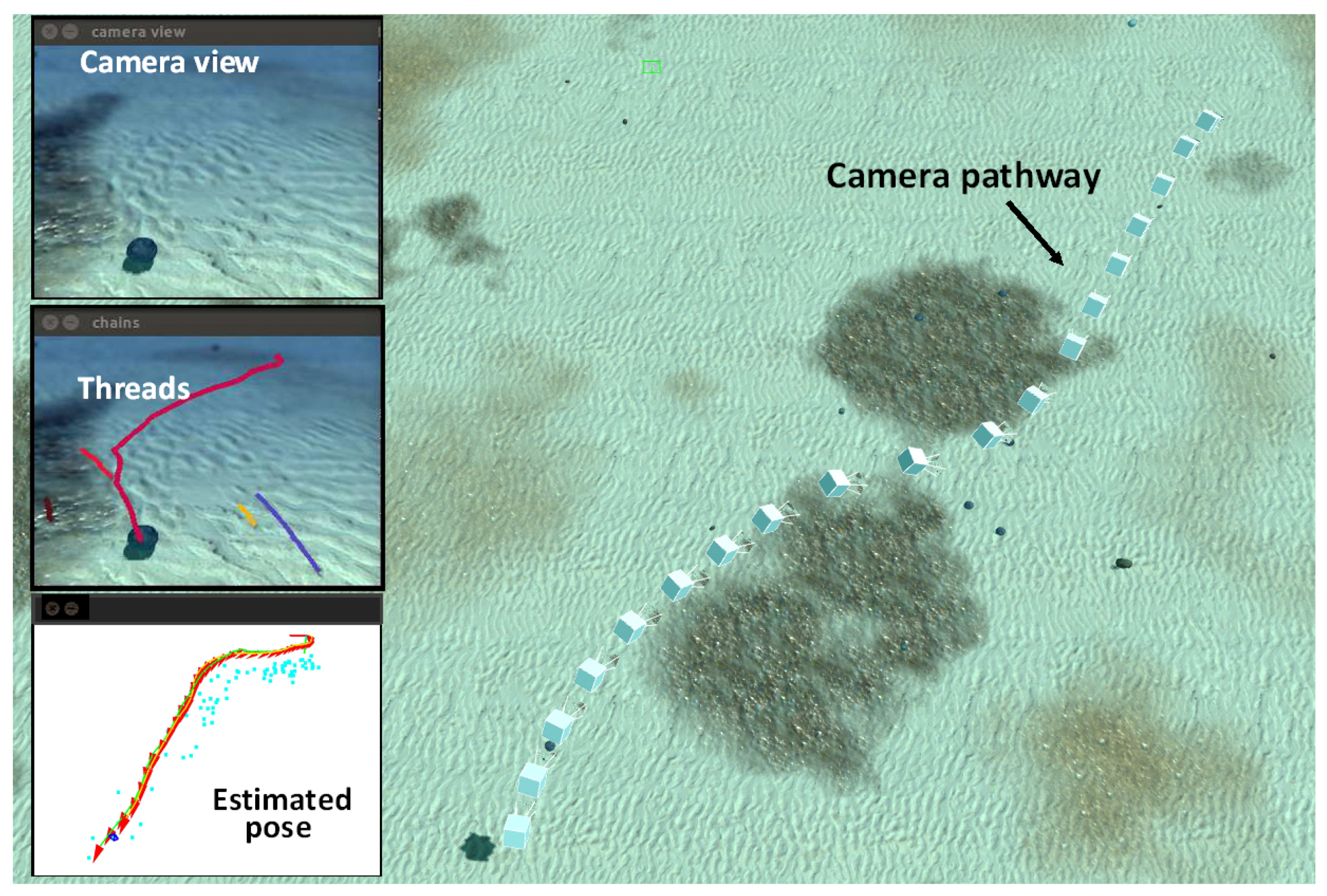
Figure 2, on the right, offers a birds-eye view in the camera pathway traversing extensive zones of sand banks and benthos during the exploration. On the left side, heading down the column, one can appreciate first a raw image of the footage, further down, the threads of robust keypoints which have passed the test of life lapses and, fully down, the estimated camera pose (in x–y view) with all the keypoints sighted on both sides of the pathway.
From the proper camera pathway in the exploration, one can observe certain attraction exerted by extensive rich-featured zones on the guidance, more precisely, by the contours of benthic assessments. This is so due to the marked changes of texture between benthos and sediment or sand. The contours are detected as described previously by scrutinizing the upper section of every frame and then selecting the zone with the highest density of keypoints therein.
However, these methods for heading generation and robust keypoint identification do not work effectively in sand banks that have rich texture but also a high self-similarity degree. The threads of keypoints originated in relief with a serrated look like furrows, have usually short length and are intermittent. Thereby, these kind of threads are, in general, completely discarded by the approach. Soils with these characteristics do not generate nodes and generally cause the commutation of the odometry-based guidance up to the moment that rich-featured regions appear again at sight.
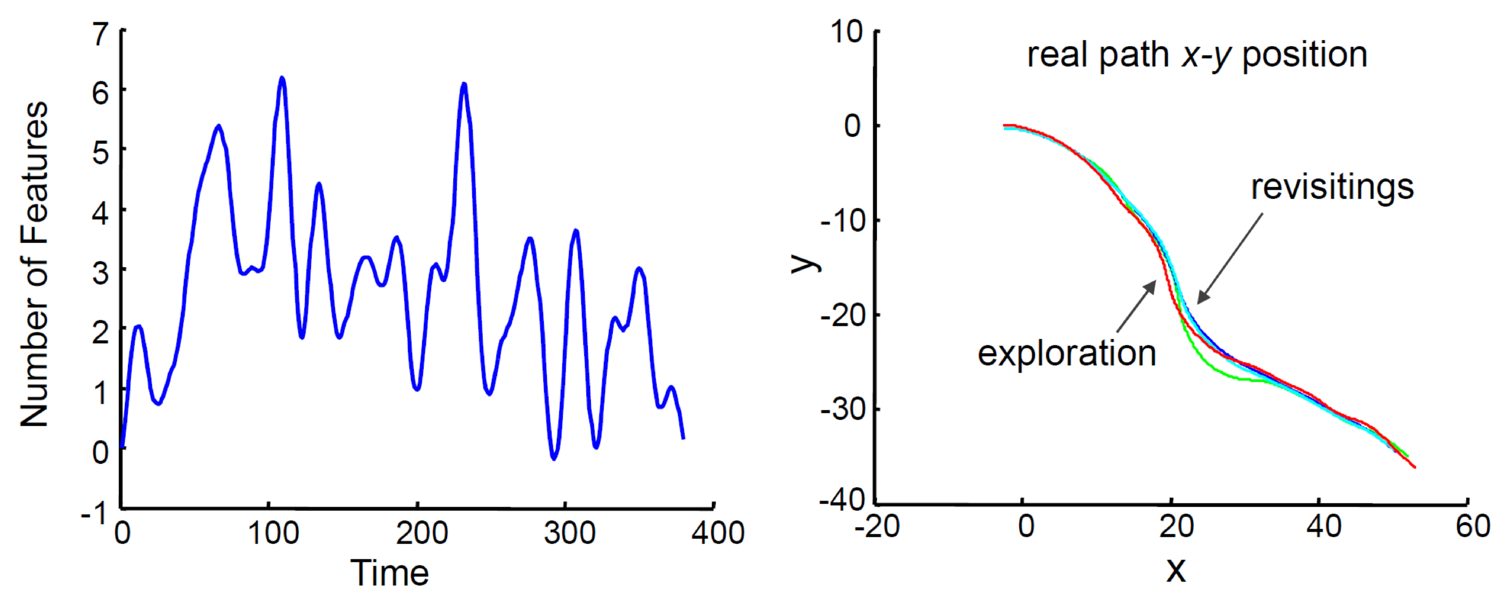
The relatively small number of robust features detected during the travel (see Figure 3, left) accounts for the difficulties of this soil for the vision-based navigation. Based on the datasets provided by the benchmark, one can compare the true pathways of the camera in the coordinates of the exploration and revisits. One ascertains a great coincidence between them attesting to the successful consolidation of the corridor.
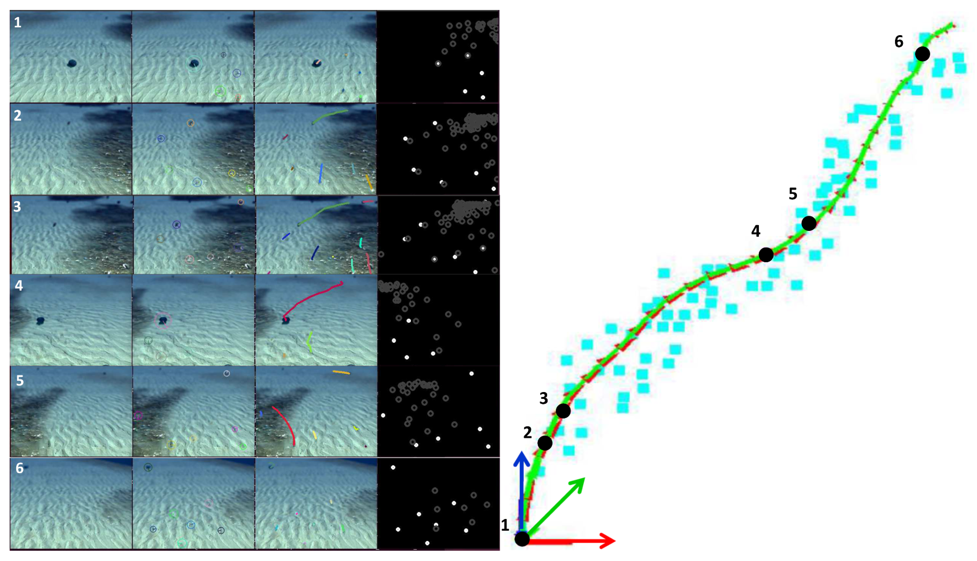
With the help of Figure 4, we will illustrate with a more thorough analysis how the characteristics of the seabed affect the decisions of the guidance system. To this end, we have selected some relevant moments of the exploration that allow us to explain the generation of headings and the identification of robust keypoints for constructing a corridor step by step.
In the Figure 4 to the right, six poses of the camera are marked with dots on the generated pathway in the metric space. The square marks account for the robust keypoints. To the left of the figure one can appreciate six rows with four images each, namely, from left to right, raw frame, keypoint description, robust keypoint trails, and the location of robust keypoints (in white dots) and nonrobust keypoints (in dark dots). Each row contains the visual information regarding the six poses marked on the pathway, see at the right in the figure.
In row 1, we observe a sparse-feature scene, with an isolated stone ahead in the middle of the vision field. Besides, far in the horizon, one can sight some dark spots, albeit blurred owing to the effects of the backscattering. Despite detecting many keypoints in the background, only a few of them pass the test of robustness. Shortly thereafter, the guidance decides to reach out to the spot at the right because of a major number of lasting features. Due to the high-textured characteristics of soil with gravel and benthic settlements, the number of keypoints increases significantly and some long-length threads begin generating (see row 2). Immediately, the guidance perceives the great amount of features and twists carefully to the right with the expectation of being able to gradually maximize the keypoint density (see row 3).
At a later time, the vehicle arrives at a place with few robust keypoints and bends slightly to the right (see row 4), but before long it changes the heading to the left when more robust keypoints are identified on this direction. So it enters a zone with a high density of features (see row 5). More ahead in the corridor, the vehicle comes into a zone of sand banks with few short keypoints threads. From there it continuously navigates via visual odometry. In this form arises a corridor in this trial for the exploration phase.
4.2. Case Study II: Natural Environment
In this case we employed a natural scenario underwater. The selected bottom offers a global self-similar appearance, a visual diffuse horizon in the comprehended space contours and a random spacial-temporal change of illumination on the floor due to sunlight caustics refracted from the rippling water surface. The navigation is led from an underwater vehicle with a monocular camera mounted at the front and directed to the bottom with different tilts between 30 and 45 degrees. The altitude is regulated at a short distance from the floor, so that the scenario looks in 3D appearance.
The raw video is broadcast in real time through a tether to a computer on land, in where the mapping, tracking and evaluation are carried out at a rate of about 30 fps. The depth is regulated on board and kept constant. For the navigation ahead, a suitable cruise velocity is given to the propellers which push the vehicle defining a course for the first time along the featured floor. At a certain point of the pathway, the vehicle returns backwards, capturing similar scenes in reverse. Thereby, the vehicle navigates to and fro many times completing round trips and consolidating in this manner a corridor between two extreme points over the floor.
For performance assessment we employ indicators of the density of successful loop closings at nodes. Ideal is that at any node of the sequence the node matching be successful, i.e., the number of identified nodes in a passing revisiting would be maximal. For the sake of achieving more robustness of the C-SLAM, we had however to allow a matching that takes place in a neighbourhood of the expected node, i.e., taking into account a number of nodes located both back and forth of the expected node. This is quite important in the case that the guidance and control systems turn aside too much from the reference pathway in the revisiting phase with respect to the reference path of the exploration.
One way to reduce the undesired impact of perturbations, like backscattering and sunlight caustics, upon mapping and tracking is to define the nodes in positions rather close each other. To this goal we propose to overlay the frames of two consecutive nodes in at least 70% or 80%. Moreover, we will refer to the reference nodes as keyframes, so there will be one keyframe per reference node in the exploration.
Another meaningful indicator in the assessment of the corridor consolidation is the progressive enhancement of the map of the bottom both locally and globally during the experiment. Moreover, a complementary sign of completion is the estimation of the camera pathways which must remain all close together along the corridor with respect to a global frame of coordinates. Here, the reference frame was the initial camera pose at the starting point in the exploring.
Finally, thorough inspection of the raw videos for recognizing clue similitudes in the scenes at time points, just at points where the indicators declare a successful loop closing, was very useful in the global analysis. Next we will describe one experiment of a series of trials documented in videos (https://www.youtube.com/watch?v=-GRBWBJtBiY, https://www.youtube.com/watch?v=jjivil48Yis).
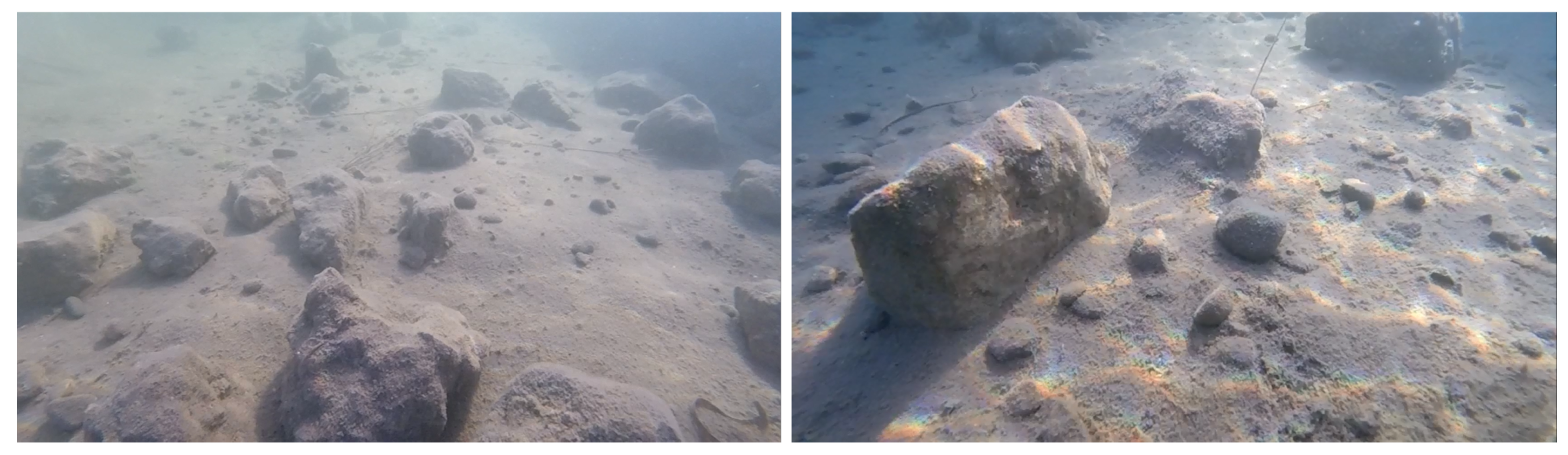
In Figure 5, some scenes underwater of the bottom during the experiment are displayed. For instance, the image to the left shows a raw frame that captured a scene with a blurred horizon, self-similar rocks and suspended particles. The image to the right on the contrary, depicts a scene with sunlight caustic waves on the floor. Both scene types are part of this experiment in different stretches of the navigation. The success of the visual system with the presence of both perturbations requires a certain degree of robustness, because in backscattered portions of the scene, features are seldom detected, and in spatio-temporal changes of illumination feature following may be interrupted.
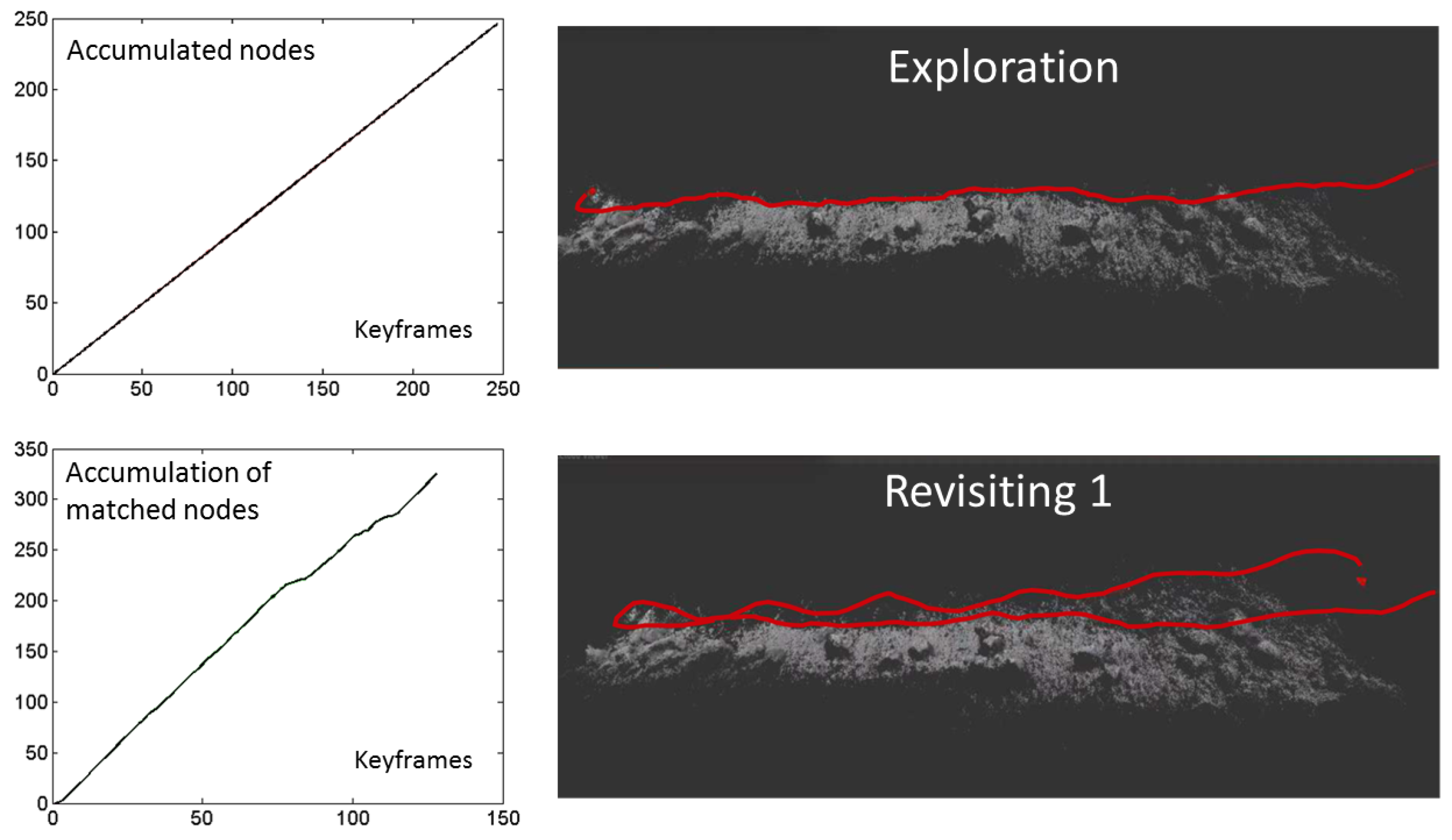
The number of successful loop closes between any camera pose in the consolidation phase along the keyframe (node) axis is portrayed in Figure 6 on the left column. One can notice a permanent, almost monotonic, increase in the number of matched nodes. This fact attests the ability of the visual system for node following in the right order of the sequence. The video of this experiment can be found in https://www.youtube.com/watch?v=jjivil48Yis.
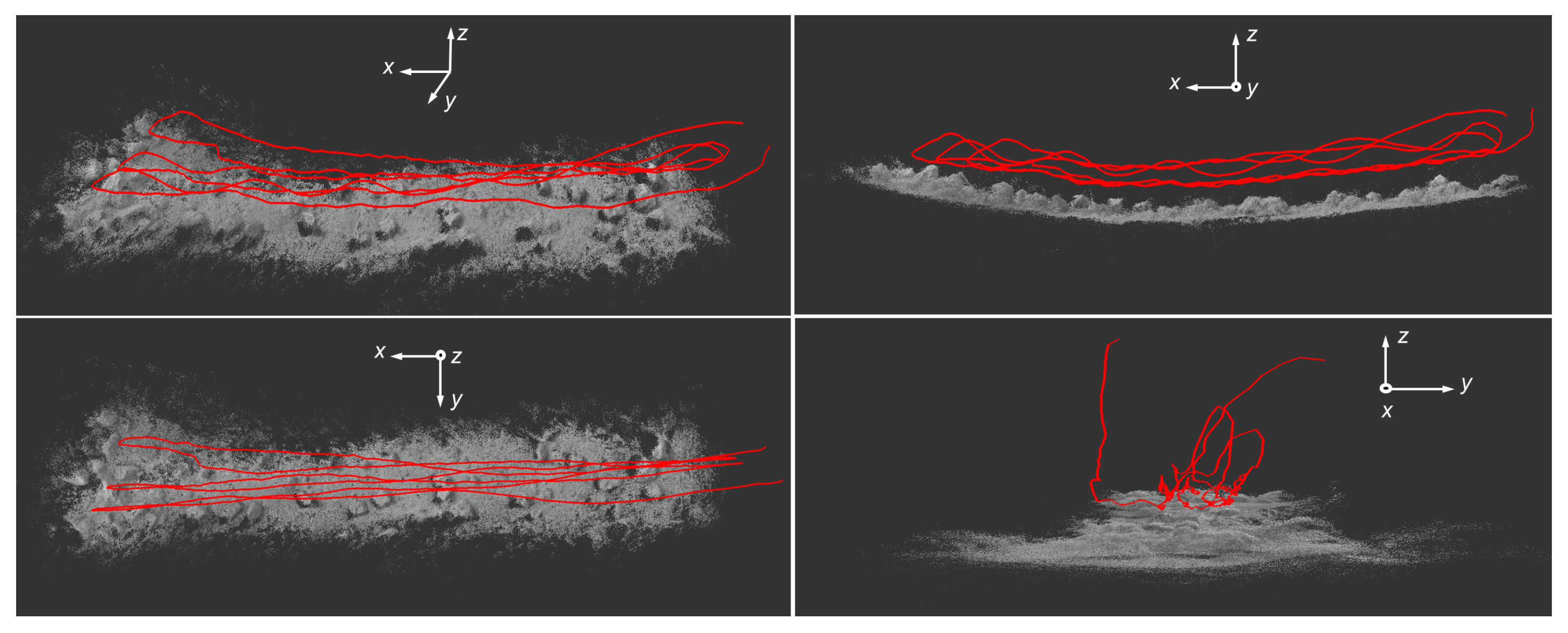
Figure 6 on the right column, depicts the process of map enhancement as the revisits, both back and forth, were progressing. The point cloud becomes gradually more and more dense, however just at end of the exploration, the corridor seems to be almost established. In Figure 7 the concluding corridor can be illustrated as the involute of all camera pathways. The dispersion of the estimated pathways in the revisits are, from one side, due to the natural drift originated in tracking, and, from the other side, owing to the usual drifts of guide and control actions. Above all, unavoidable vehicle oscillations in pitch mode caused undulations in the camera pathway which were reproduced by large deviations of the estimates in the z axis. This fact was verified in the inspection of the camera footage when the horizon line at top of the image moves up- and downwards periodically.
4.3. Technical Remarks
We will merely describe some technical obstacles that we have encountered in the experiments and that might affect to some extent the success of the approach. Common difficulties are found in the adequacy of the image for SLAM purposes. Events that can occur, like lost frames, lighting over- and sub-exposures and rolling shutter in the image capture, are mainly hardware-related. Best results could be obtained with a camera with a global shutter and automatic exposure. We employed a camera GoPro Hero 4 Session. This camera uses a rolling-shutter capture method, however, its high frame rate of about 120 fps enabled the dissembling of the rolling shutter effect. With our computing hardware on land, we achieved an image processing with rates over 30 fps, with size 380 × 240 for mapping and 640 × 480 for tracking, and a FOV (Field of View) of 90 degrees underwater. The employed laptop possesses a processor Intel Core I7-6700HQ Quad Core and the operating system Ubuntu version 16.04. Eventual vehicle shadows during the experiments and object occlusions at low altitude were not a significant source of possible malfunctioning.
5. Conclusions
This paper has dealt with the development of a node-based monocular visual methodology for autonomous vehicle navigation which has the goal of exploring unknown regions of the sea bottom and revisiting them in another instance. The work accentuates some characteristics of the seabed like the self-similarity and backscattering, which are potential sources of uncertainty wherein state-of-the-art SLAM would fail in general.
While similar methods mentioned in the paper use active SLAM and employ two degrees of freedom for map building, our approach generates a curve in one degree of freedom, i.e., a corridor composed of linked nodes. On one side the nodes are selected optimally in the sense of searching for the next node in the direction that points to a zone of maximal density of detected features in the frame. On the other side, it is expected that the revisits of nodes at each step has a higher success rate than in the case of two degrees of freedom. This is supported by the fact that the approach tries to match nodes in an strict order and thereby the loop closure is almost permanent.
For selection of robust features whose identification is to some extent insensible to changes of viewpoints, we have employed live lapses of features able to be tracked. The hypothesis of robustness lies in the expectation that features with long threads are more robust than in the case of sporadically detected features. Moreover, the threshold value for robust feature selection is put just on the median of the histogram of the live lapses in order to dynamically adjust the method to the texture and relief characteristics of the floor. How right the hypothesis was, it could be validated both in simulation and experiments by the high density of loop closures in the revisits.
In principle, when a chain of nodes is constructed and these are well separated each other, the vehicle can revisit them orderly by applying intermittently a visual-odometry-based guidance on a feature-poor stretch and a following feature tracking for loop closing over predominantly feature-rich zones. In multiple passes along the corridor, the success rate in loop closings should be enhanced if the strategy of nodes selection is refined by increasing or modifying the thresholding for robust features. Moreover, the potential adaptation of the approach to characteristics of the environment which vary slightly in time, seems a-priori to be straightforwardly possible by the proper tuning of thresholds.
In real-world experiments, it was ascertained that the robustness was practically manifested when the condition of node matching under strict order is relaxed. In this case the matching with three or four nodes around the expected node instead of the node self, increases the success rate. Additionally, the robustness was improved if the nodes are selected rather close together in the chain. Moreover, it was shown that the success rate of travelling from end to end of the corridor can be reinforced if the system tracks the camera pathway instead of tracking features.
Even when the method provides a feasible corridor, there is no awareness about the global coordinates to describe the trajectory. So the corridor may not describe neither the shortest distance path nor an optimal one between two points; its position remains uncertain, rather it might look erratic, but the objective of the approach to be able to safely travel through the corridor hence and forth would be accomplished.
These conclusions were supported above all by two case studies. The first one involves a series of simulations employing an ad-hoc benchmark of the sea bottom with different degrees of self-similarity and backscattering. The second case study involves experiments in a natural environment. The real-world experiments tried to illustrate potentials and limitations of the visual system in different settings involving design and operational parameters as well as real environmental conditions like perturbations of the type of sunlight caustic waves and vehicle own shadow on the bottom. Limitations of the approach applicability can be attributed above all to camera technology which commonly requires a wide FOV, global shutter characteristics and a high frame rate, e.g., 60 fps. With a good computational hardware at land for the experimental part, it was possible to process 30 fps in real time.
Overall, these preliminary results attest the feasibility of the approach for potential applications in the field of autonomous navigation underwater.
Author Contributions
The authors concieved the ideas, designed the experiments and wrote the paper in joint effort.
Conflicts of Interest
The authors declare no conflict of interest.
References
- Lowry, S.; Snderhauf, N.; Newman, P.; Leonard, J.J.; Cox, D.; Corke, P.; Milford, M.J. Visual Place Recognition: A Survey. IEEE Trans. Robot. 2016, 32, 1–19. [Google Scholar] [CrossRef]
- Cadena, C.; Carlone, L.; Carrillo, H.; Latif, Y.; Scaramuzza, D.; Neira, N.; Reid, I.D.; Leonard, J.J. Past, Present, and Future of Simultaneous Localization And Mapping: Towards the Robust-Perception Age. arXiv, 2016; arXiv:1606.05830v2. [Google Scholar] [CrossRef]
- Horgan, H.; Toal, D. Computer Vision Applications in the Navigation of Unmanned Underwater Vehicles. In Robotics, Mobile Robotics, “Underwater Vehicles”; Inzartsev, A.V., Ed.; InTech: Rijeka, Croatia, 2009; Chapter 11; ISBN 978-953-7619-49-7. [Google Scholar]
- Agarwal, S.; Lazarus, S.B.; Savvaris, A. Monocular Vision Based Navigation and Localisation in Indoor Environments. IFAC Proc. Vol. 2012, 45, 97–102. [Google Scholar] [CrossRef]
- Lindsey, G.R. The Submarine Environment. Available online: http://www.tandfonline.com/doi/abs/10.1080/00396336408440456 (accessed on 3 March 2008).
- Trabes, E.; Jordan, M.A. On-line Filtering of Sunlight Caustic Waves in Underwater Scenes in Motion. In Proceedings of the 7th International Scientific Conference on Physcon, Istanbul, Turkey, 19–22 August 2015. [Google Scholar]
- Trabes, E.; Jordan, M.A. Self-Tuning of a Sunlight-Deflickering Filter for Moving Scenes Underwater. In Proceedings of the 2015 XVI Workshop on Information Processing and Control (RPIC), Córdoba, Argentina, 6–9 October 2015. [Google Scholar]
- Shechtman, E.; Irani, M. Matching Local Self-Similarities across Images and Videos. In Proceedings of the IEEE Conference on Computer Vision and Pattern Recognition—CVPR, Minneapolis, MN, USA, 17–22 June 2007; pp. 1–8. [Google Scholar]
- Goedemé, T.; Tuytelaars, T.; Van Gool, L. Visual Topological Map Building in Self-similar Environments. In Informatics in Control Automation and Robotics; Springer: Berlin/Heidelberg, Germany, 2008; pp. 195–205. [Google Scholar]
- Furgale, P.; Barfoot, T.D. Visual Teach and Repeat for Long-Range Rover Autonomy. J. Field Robot. 2010, 27, 534–560. [Google Scholar] [CrossRef]
- Chaves, S.M.; Eustice, R.E. Efficient planning with the Bayes tree for active SLAM. In Proceedings of the International Conference on Intelligent Robots and Systems (IROS), 2016 IEEE/RSJ, Daejeon, Korea, 9–14 October 2016. [Google Scholar]
- Maurovi, I.; Seder, M.; Lenac, K.; Petrovi, I. Path Planning for Active SLAM Based on the D* Algorithm with Negative Edge Weights. In IEEE Transactions on Systems, Man, and Cybernetics: Systems; IEEE: Piscataway, NJ, USA, 2017; Volume PP, pp. 1–11. [Google Scholar]
- Mu, B.; Giamou, M.; Paull, L.; Agha-mohammadi, A.A.; Leonard, J.; How, J. Information-based Active SLAM via topological feature graphs. In Proceedings of the IEEE 55th Conference on Decision and Control (CDC), Las Vegas, NV, USA, 12–14 December 2016. [Google Scholar]
- Clarkson, K.L. Fast Algorithms for the All Nearest Neighbors Problem. In Proceedings of the 24th IEEE Symposium Foundations of Computer Science, Tucson, AZ, USA, 7–9 November 1983; pp. 226–232. [Google Scholar]
- Farnebäck, G. Very High Accuracy Velocity Estimation using Orientation Tensors, Parametric Motion, and Simultaneous Segmentation of the Motion Field. In Proceedings of the 8th IEEE International Conference on Computer Vision (ICCV), Vancouver, BC, Canada, 7–14 July 2001. [Google Scholar]
- Bay, H.; Ess, A.; Tuytelaars, T.; Van Gool, L. SURF: Speeded Up Robust Features. Comput. Vis. Image Underst. 2008, 110, 346–359. [Google Scholar] [CrossRef]
- Klein, G.; Murray, D. Parallel Tracking and Mapping for Small AR Workspaces. In Proceedings of the 6th IEEE and ACM International Symposium on Mixed and Augmented Reality, ISMAR 2007, Nara, Japan, 13–16 November 2007; pp. 225–234. [Google Scholar]
Figure 1.
Heuristics for generating a corridor employing a visual feature-based guidance with two stages. Description of an example. Stage 1: The system starts from pose . In the presence of a poor-featured soil, it selects a direction and compels a straight-ahead navigation. After a while, at , one achieves a field of view from where many features are observed. is the odometry-based pose. Stage 2: The system navigates from and defines a path that points to the maximal density of features. After a while, it arrives at a region with a poor textured bottom and fixes a node of reference with heading . The system defines a promissory direction to continue navigating. It begins anew stage 1.
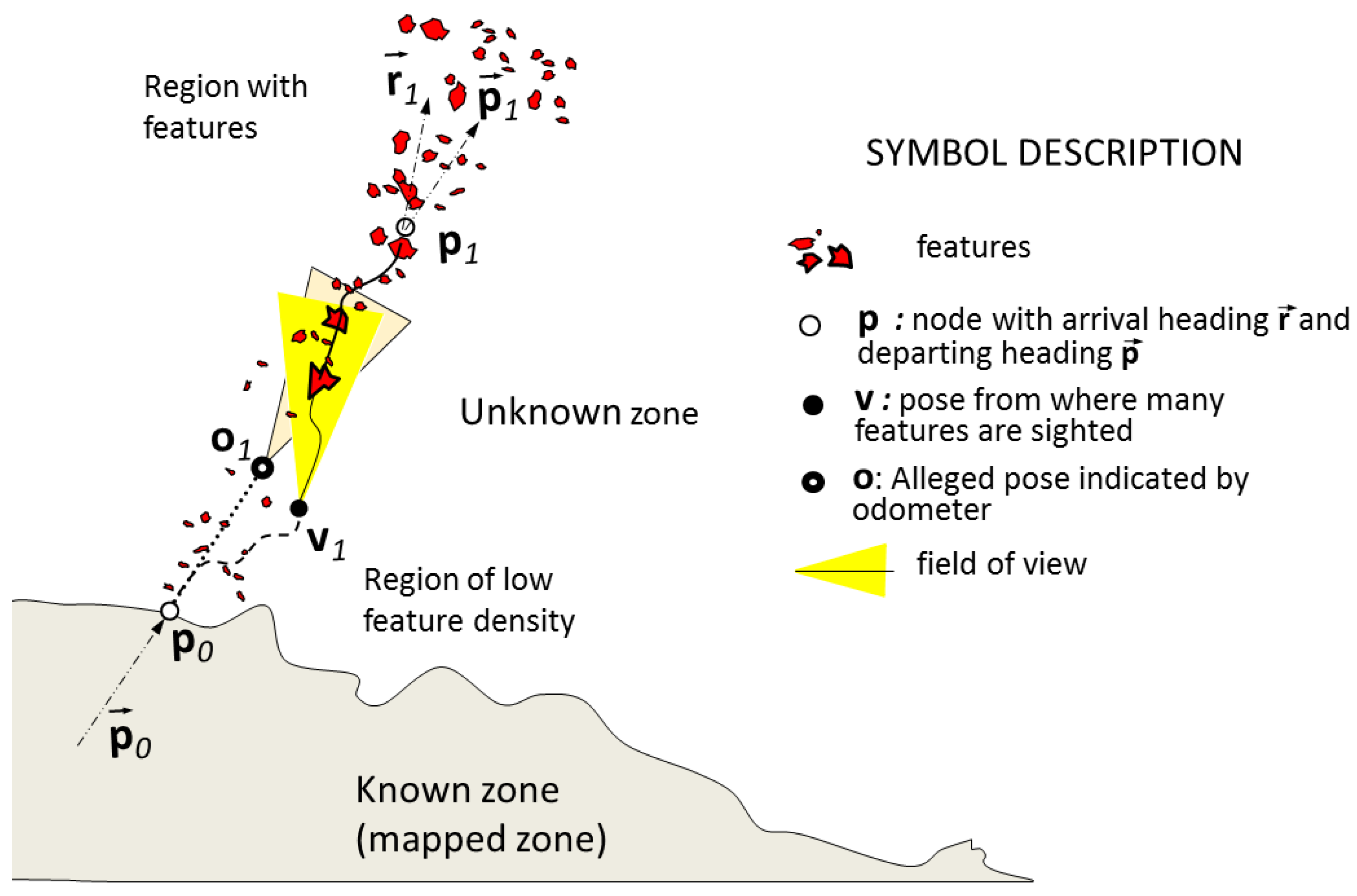
Figure 2.
Benchmark for subaquatic environments. Simulation of sand banks.

Figure 3.
Left: evolution of the detected robust features; Right: true camera pathways in the exploration and consolidation.
Figure 3.
Left: evolution of the detected robust features; Right: true camera pathways in the exploration and consolidation.

Figure 4.
Heading generation and keypoint description during the construction of a corridor. Left: six relevant poses of the camera in its pathway described in 6 rows. Each row, from left to right: raw frame, keypoint description, robust keypoint trails and finally, location of robust keypoints (in white dots) and nonrobust keypoints (in dark dots). Right: estimated camera pathway with indication of the six relevant poses (in dots) and the position of the detected features (in squares).

Figure 5.
Scenario underwater. Left: captured scene with blurred horizon, self-similar rocks and suspended particles. Right: scene with sunlight caustic waves on the floor.
Figure 5.
Scenario underwater. Left: captured scene with blurred horizon, self-similar rocks and suspended particles. Right: scene with sunlight caustic waves on the floor.

Figure 6.
Corridor building. Left column: the accumulation of nodes and node matching in time. Right column: progressive enhancement of the corridor map in each revisiting.
Figure 6.
Corridor building. Left column: the accumulation of nodes and node matching in time. Right column: progressive enhancement of the corridor map in each revisiting.

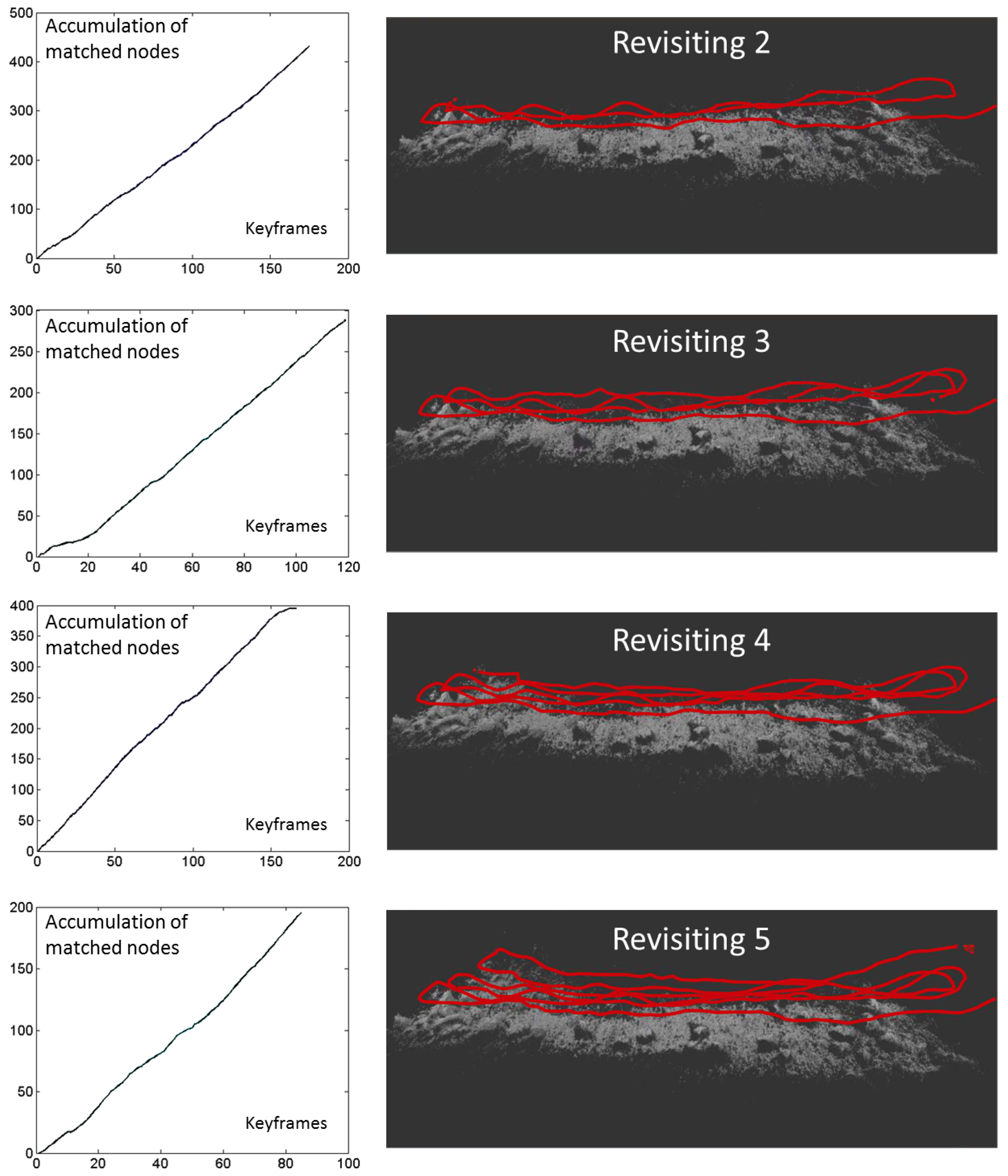
Figure 7.
Built corridor from different perspectives.

© 2017 by the authors. Licensee MDPI, Basel, Switzerland. This article is an open access article distributed under the terms and conditions of the Creative Commons Attribution (CC BY) license (http://creativecommons.org/licenses/by/4.0/).
Share and Cite
MDPI and ACS Style
Trabes, E.; Jordan, M.A. A Node-Based Method for SLAM Navigation in Self-Similar Underwater Environments: A Case Study. Robotics 2017, 6, 29. https://doi.org/10.3390/robotics6040029
AMA Style
Trabes E, Jordan MA. A Node-Based Method for SLAM Navigation in Self-Similar Underwater Environments: A Case Study. Robotics. 2017; 6(4):29. https://doi.org/10.3390/robotics6040029
Chicago/Turabian StyleTrabes, Emanuel, and Mario Alberto Jordan. 2017. "A Node-Based Method for SLAM Navigation in Self-Similar Underwater Environments: A Case Study" Robotics 6, no. 4: 29. https://doi.org/10.3390/robotics6040029
Note that from the first issue of 2016, this journal uses article numbers instead of page numbers. See further details here.