1. Introduction
Robot-assisted therapy in neurorehabilitation after stroke or spinal cord injury is indicated to be an effective way of treatment [
1,
2,
3], in order to support physiotherapists and due to this increase the treatment time for patients. Especially patient-cooperative rehabilitation robots, that are taken into account the patient’s intention and behavior as well as maximize the patient’s voluntary effort, are proposed to have a high potential to improve robot-assisted rehabilitation [
4,
5,
6,
7,
8]. In the design of those rehabilitation robots, an essential aspect is the physical human-robot interface, which should provide a safe human-robot interaction (HRI) with high comfort for the user. Another critical point in the design is to include suitable force/torque sensors (FTS) to provide a measurement of interaction forces, that is used for development of interaction control strategies as well as information for visual feedback of amount of patient’s participation, which is useful to increase patient’s motivation.
The most common way to measure HRI forces/torques is to apply mostly very expensive but high precision 6-axis FTS between the cuff of the HRI interface and the robot link of exoskeletons [
9] or robot’s end-effector [
10,
11]. Besides high costs, another drawback of this solution is the single-point connection and force/torque transmission which leads to a limitation in flexibility of design. Furthermore, it should be advantageous to measure interaction forces at the whole interface and not only at one specific point, because as described in [
12] each region of human body has a specific pressure threshold that identifies pain. Surface electromyography (EMGs) is also used as an additional input to get information about patient’s intention to perform particular movement. Examples of EMGs-controlled systems have been proposed by Kiguchi, et al. [
13] for shoulder rehabilitation and W-EXOS [
14] for forearm and wrist rehabilitation. But the disadvantage of EMG-applications is, that they have to be attached directly on the skin surface, which is perceived by many people as unpleasant.
A low-cost distributed tactile sensor, based on silicon Skilsens sensitive pads, that measures pressure distribution over the user’s skin without requiring any change to the design of the human-robot interface is presented in [
15]. Deformation of these sensitive pads reduces light that is emitted along the horizontal axis, resulting in a change of output voltage. However, this sensor system does only measure pressure distribution as indicator of interaction forces, but not the real interaction forces/torques between the robot and the user.
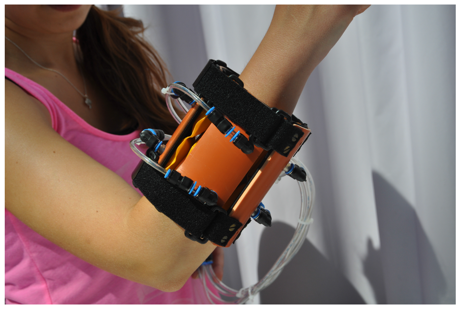
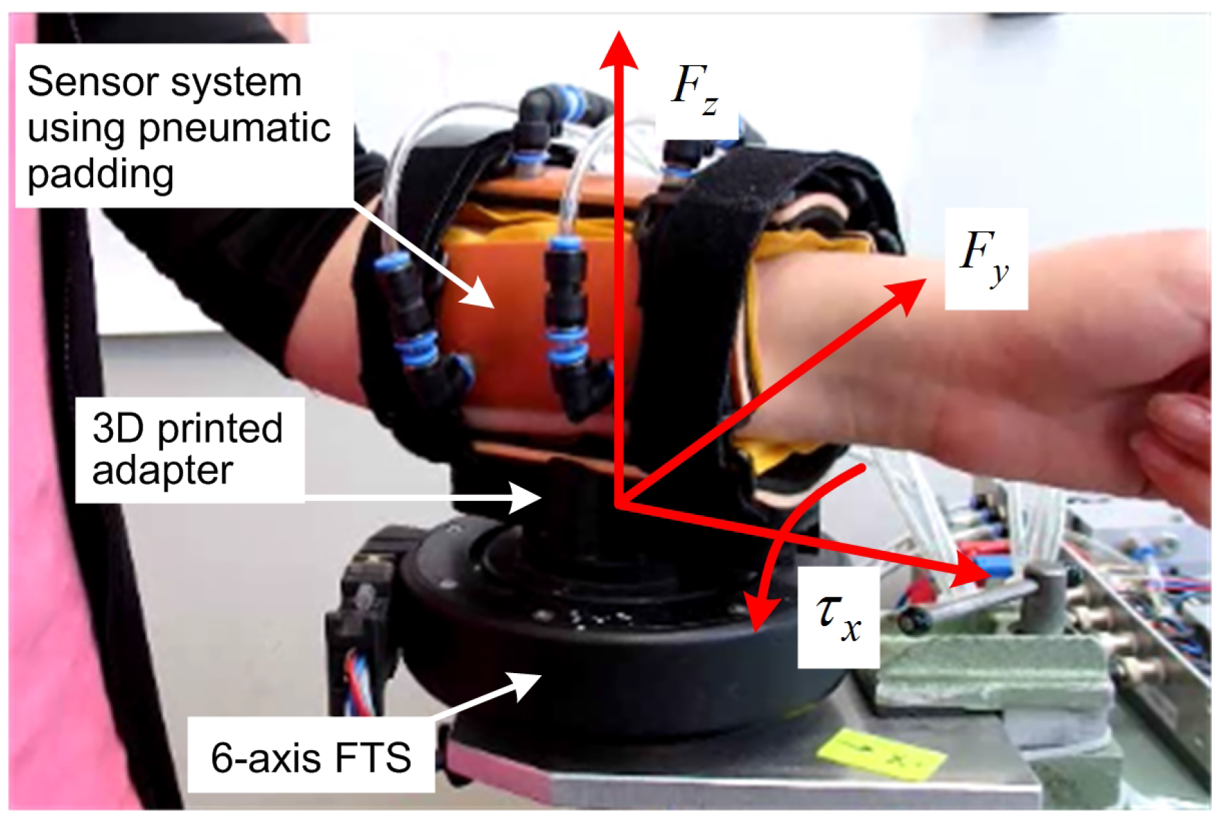
In this paper, a first prototype of a novel cost-effective interaction sensor system using pneumatic padding is presented, see
Figure 1, to estimate roughly HRI forces/torques for visual feedback or additional information to realize suitable interaction controllers. Furthermore, the developed system can be easily integrated in the design of physical interfaces. The sensor system is based on eight air-pad chambers, that can be directly integrated in the cuff of human-robot interfaces, used to measure pressure distribution as well as to provide a safe physical HRI with high user’s comfort. The pneumatic padding can be adapted to the individual shape of the user’s extremity by changing the pressure in pneumatic chambers. A set of artificial neural networks (ANNs) is used to estimate interaction forces/torques based on pressure variations in air-pads. Presented in this paper is the concept of pneumatic padding, including the design, the realized prototype and the basic force/pressure characteristic of air-pads. Furthermore, a simple force/pressure based method to estimate interaction force in one direction is shown as well as a concepts based on ANNs to estimate all HRI forces/torques. The experimental results performed show a validation of both estimation concepts in comparison to a high precision FTS used as reference system. The estimation algorithm is tested with three subjects without retraining the ANNs to confirm functionality.
2. Concept of Pneumatic Padding
Especially the design of safe physical human-robot interfaces providing high user’s comfort is an essential aspect in development of rehabilitation robots. The key idea for the development of the pneumatic padding is to use cost-effective pneumatic air-pads in the cuff of the interface directly to estimate HRI, with the objective to avoid the use of 6-axis FTS that are commonly used to measure HRI forces/torques. Those sensors are mostly mounted between the cuff of the interface and the robot link or end-effector which leads besides high costs to a limitation in the flexibility of the robot design.
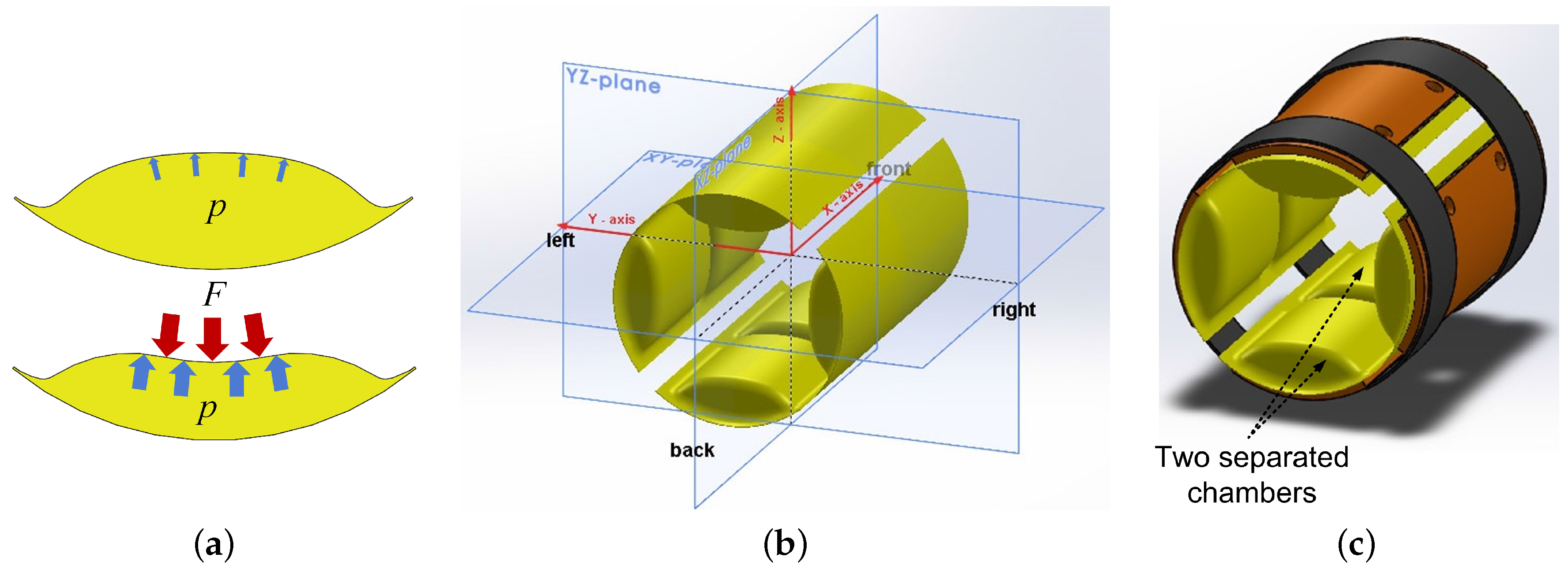
The main component of the proposed sensor system are self-made cost-effective air-pads that are placed in shells. Those air-pads are used on the one hand to realize high user’s comfort, because by changing of the initial pressure in pads, the padding can be adapted to the individual shape of user’s limbs, and on the other hand, to directly estimate HRI forces/torques based on observing the change of pressure in all air-pads. An illustration of one pressurized air-pad without and with acting interaction force is shown in
Figure 2a.
For basic investigations, different realizations of the pneumatic padding with different number and arrangements of air-pads were used and a comparison shows, that the use of 4 air-pads is sufficient to estimate forces in the two-dimensional space (one for each direction). However, to estimate forces in three-dimensional space, it was required to split each air pad into two sections, defined as front and back section. Furthermore, in this way not only the forces in x, y and z-direction can be observed and distinguished, but also the three resulting torques around the x, y and z-axis. Realizations with more than 4 air-pads were also considered, but are not used, because of increasing system complexity with a comparable less improvement for estimation procedure.
The number of shells is another important factor for the required variable scope and comfort. With a few big shaped shells, the user will feel like his arm is stucked in the tubular structure fully enclosed. More shells, on the other hand, will increase the flexibility of the design and the user should feel more comfortable. In order to provide flexibility and produce a design compatible with different limb diameters, the single shells are connected with belts. Since the design should fit for users with small and large arm circumference, different anthropometric data was investigated. In order to avoid contact or overlapping of shells, the smallest forearm radius was chosen as basis for the prototype development, according to [
16]. The construction was developed symmetrically to allow the use for the right or left limb. The working principle is suitable for upper and lower extremities as well. The construction is intended to allow the components to be easily replaced when necessary. The 4 air-pads divided into two chambers in the arrangement used for the pneumatic padding are shown in
Figure 2b and the final design with cuff is shown in
Figure 2c.
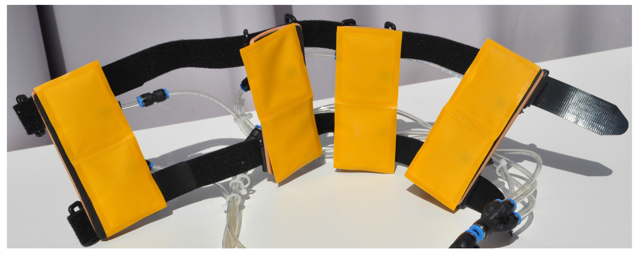
Based on the above described design, a first prototype of the pneumatic padding for the lower arm was created as possible application example, see
Figure 1 as well as
Figure 3. A major advantage of this sensor system are low production costs and this important feature is achieved by using widespread electronic components, low-cost materials and a simple but trustful fabrication process. The air-pads were manufactured by the company Dr. Winkler GmbH & Co. KG (Ainring, Germany) as one of the project partners and are made of nylon-polyurethane foil that is pressure resistible, flexible but not elastic, to avoid nonlinear behavior. In the production, the foils were welded together by using high frequency welding, that is considered to be one of the highest quality methods of joining thermoplastic materials. For measuring the pressure in each chamber of air-pads, eight cost-effective pressure sensors (AMS 5812, AMSYS GmbH & Co. KG, Mainz, Germany) are used.
As reference sensor system, the experimental setup, used to verify the concept, also includes a high precision 6-axis FTS (C-FTS, V2.05-40F, DLR), see
Figure 4. For accurately connection of the prototype to the reference sensor, an adapter with individual geometry was developed using 3D printing. The developed prototype can be seen as an integral part of orthosis mechanical structures and therefore stays unobtrusive for the user.
3. Force/Pressure Characteristic of Air-Pads
With the objective to provide high user’s comfort, the pneumatic padding can be adjusted to the individual shape of the human’s extremity by changing of the initial pressure in air-pad chambers. External forces caused by patient’s activity will change the pressure inside the air-pads, which is used to estimate HRI forces/torques.
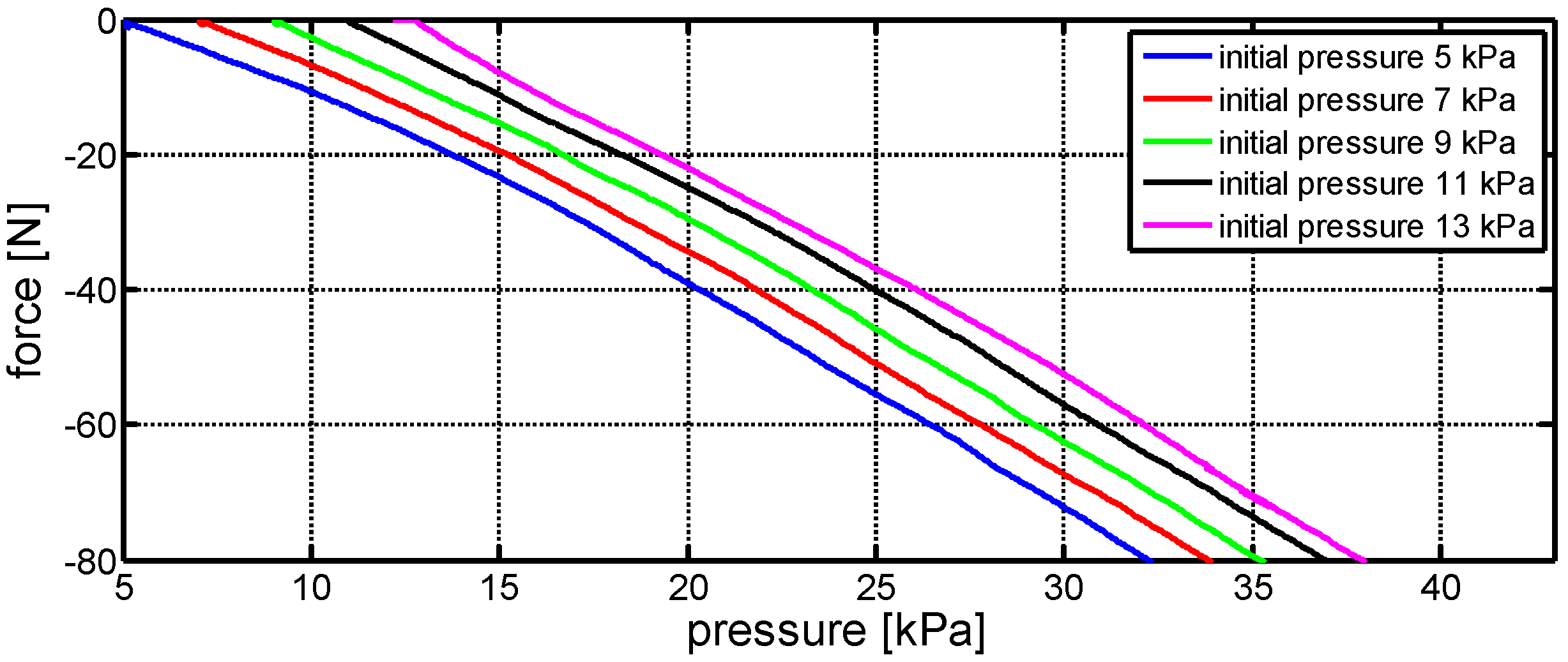
To determined the influence of changing external forces as well as the influence of using different initial pressures in air-pads, a characteristic describing the force/pressure relationship of one chamber of air-pad has been determined in experimental manner. As reference sensor, the high precision 6-axis FTS was used, as shown in
Figure 4. On the top of the shell that is connected to the FTS via the adapter, one air-pad was placed in a way to measure external forces in vertical direction. To determine the force/pressure characteristic, an external vertical force was applied to the air-pad. This force was increased continuously while the measured data of the FTS and the pressure sensor was captured and stored. The same experiment was repeated with different initial pressures in the air-pad to verify the influence. The resulting characteristic showing the relation between external force and pressure in the air-pad chamber is as follows
showing an almost linear behavior between force
F and pressure
p in air-pad chamber with an offset
as influence of changing the initial pressure, see
Figure 5. As shown in
Section 5.1, this characteristic can be used to estimate the HRI force in one direction. However, to use this characteristic as basis to determine a model of the whole pneumatic padding to estimate the 6 HRI forces/torques will lead to very complex solutions. Because of this, an force/torque estimation based on ANNs has been developed as presented in the following section.
4. Force/Torque Estimation Using Artificial Neural Networks
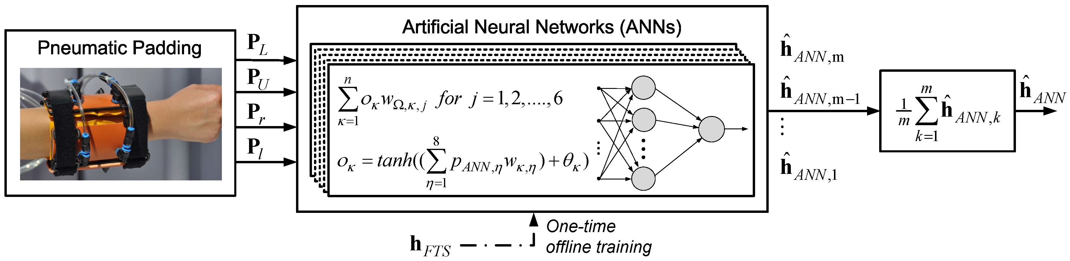
To estimate the interaction forces/torques with the pneumatic padding based on measured data of the eight pressure sensors, a set of ANNs is used. The ANNs are structured as multilayer feed-forward networks, each with one hidden layer, as shown in
Figure 6, and were trained one-time offline using the output data of the high precision 6-axis FTS based on the Levenberg-Marquardt backpropagation algorithm using the Neural Network Toolbox provided by Matlab (The MathWorks GmbH, Ismaning, Germany). The vector of HRI forces/torques
estimated based on the ANNs is defined as
where
and
are estimations of
as well as
. The
jth element of the estimated vector
of the
kth neural network is calculated based on the approach developed by McCulloch and Pitts, for instance presented in [
17], as follows
Herein,
n is the number of hidden neurons used and
is a weighting factor. The output of the
κth hidden neuron
is calculated as follows
Herein,
is a weighting factor,
is a threshold and
is the
ηth input of the input vector for the ANN that is defined as
, where
,
and
as well as
are the vectors of front and back chamber pressure of lower, upper, right and left air-pads, measured using the pressure sensors.
5. Experimental Results
The objective of the experiments performed is to analyze the possibility to estimate interaction forces/torques provided by different subjects using the proposed sensor system. As reference system, the high precision 6-axis FTS is used, that is mounted under the pneumatic padding as shown in
Figure 4. In this way both sensor systems can be used to detect and compare the interaction forces/torques provided by subjects.
To gain first experiences with the pneumatic padding, without using the ANNs, in the first experiment (see
Section 5.1), force estimation was only performed in z-direction using the experimental determined force/pressure characteristic, presented in
Section 3, as direct mapping between interaction force to air-pad pressure.
Afterwards, in the second experiment (see
Section 5.2), the ANNs were used for estimation process as described in
Section 4. To verify the concept and confirm functionality, four experiments are performed with three different subjects, whereby the ANNs are just trained with one subject. The goal was to verify if it is possible to estimate interaction forces/torques also if different subjects are using the system without retraining the networks or if this is just possible with the subject who trained the networks.
5.1. Force/Pressure Model Based Estimation
To estimate the interaction force in z-direction, the force/pressure characteristic (see
Section 3) determined in experimental manner was used as direct mapping between pressure in air-pad chambers to interaction force. For this experiment only the upper and lower air-pads are used and the resulting interaction force in z-direction
is calculated based on Equation (
1) using an analytical approach as follows
The goal was to verify if it is possible to determine the HRI in such a simple way. For the experiment, the pneumatic padding was used by the subject like shown in
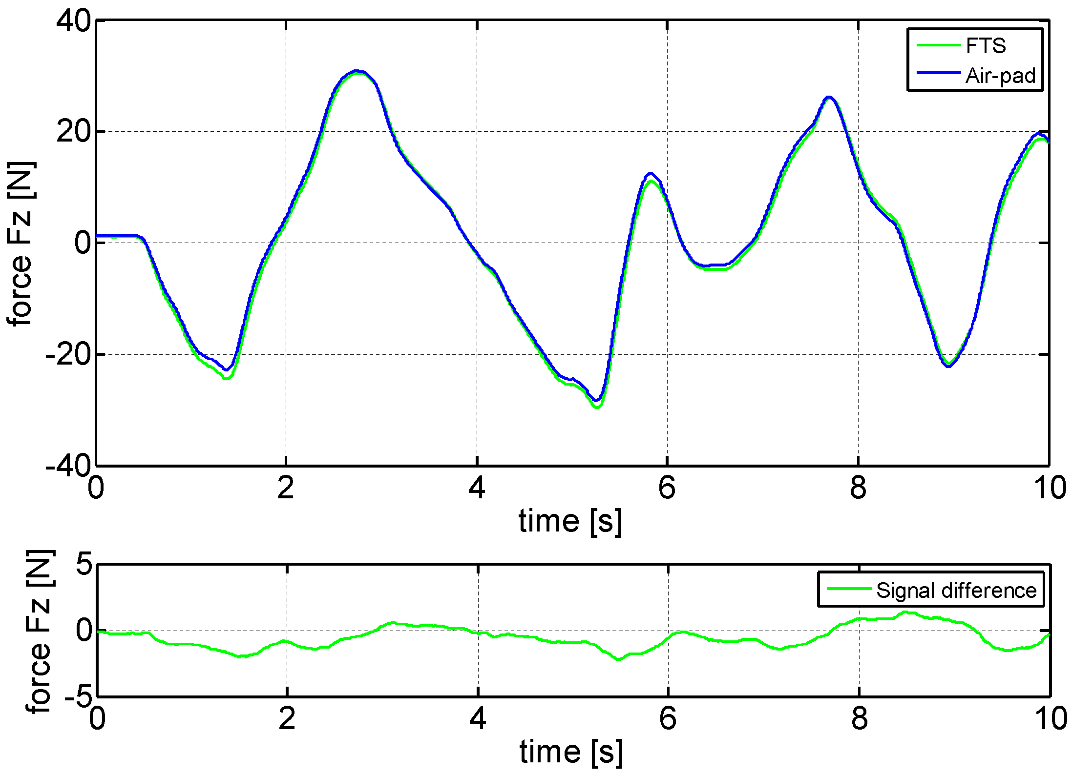
Figure 4 and during the test, the subject was asked to perform force only in z-direction. A comparison of estimated HRI force using the pneumatic padding to the measured force using the high precision FTS is shown in
Figure 7. The first plot shows the measured force using the FTS as reference system in green and the estimated force using the pneumatic padding based on Equation (
5) in blue, the second plot shows the resulting signal difference. It can be concluded, that the force estimation in one direction is possible with the pneumatic padding, with a maximum force difference of approximately
N, using the basic force/pressure characteristics as mapping.
5.2. ANN Based Estimation
The goal of this experiment was to show if it is possible to estimate the two forces and the one torque in the frontal plane of the subject. For the experiments performed
ANNs are used, each with a number of
hidden neurons, see
Section 4. The same experiment was repeated four times with three subjects, that were asked to apply only forces in y and z-direction as well as torque around the x-axis, see
Figure 4. The experimental results of one experiment with subject 1, that trained the ANNs according to the procedure presented in
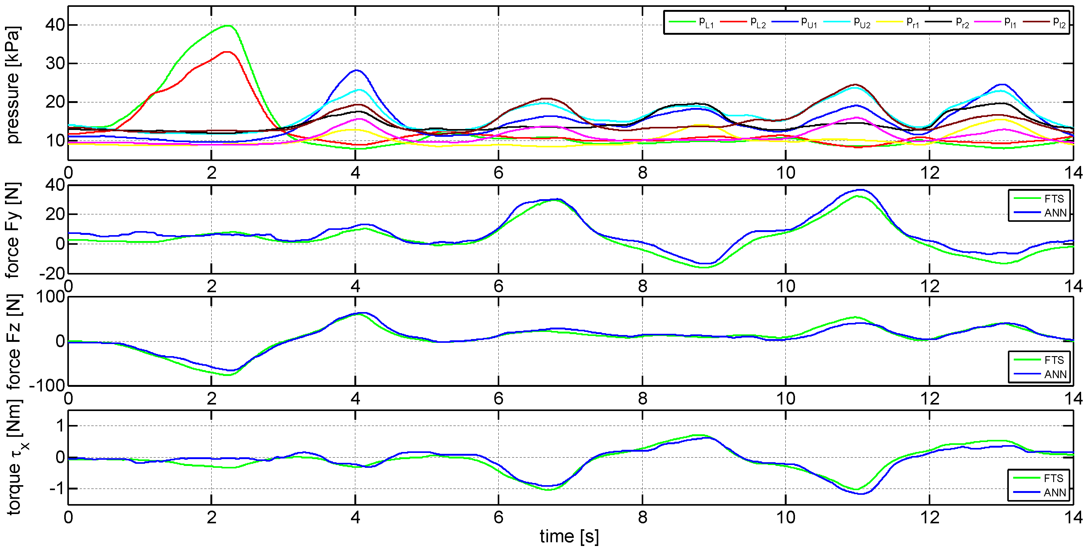
Section 4, are shown in
Figure 8 as an example. Shown in the first plot are the current pressures of the eight chambers of pneumatic padding used as input for the ANNs, according to Equation (
3). The second plot shows the measured force in y-direction using the reference FTS (green line) as well as the pneumatic padding using ANN (blue line). The third plot presents the measured force in z-direction and the fourth plot the torque around the x-axis. The result shows, that it is possible to use ANNs in combination with the pneumatic padding to estimate roughly HRI forces/torques based on pressure variations if the subject that is using the system has also trained the networks previously.
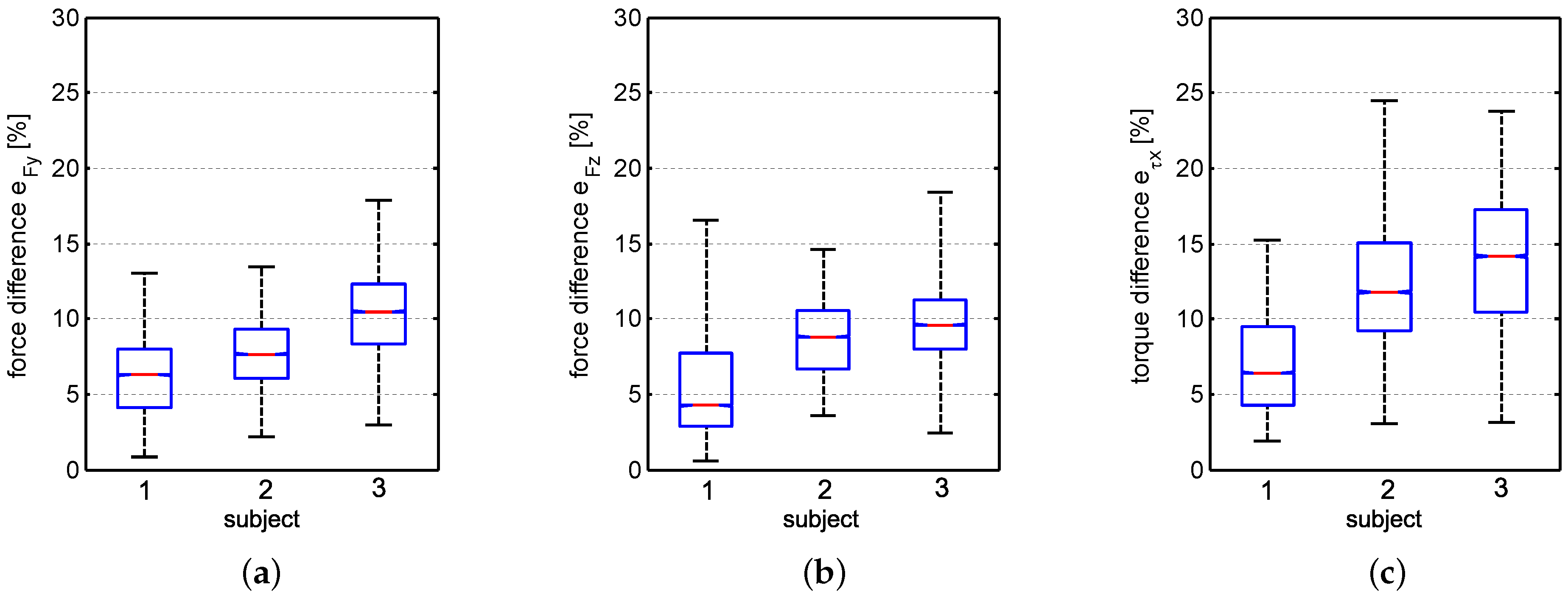
The same experiment was repeated four times with three different subjects to analyze the resulting average force difference of the four experiments for each subject. The experimental results are presented in
Figure 9. The force difference in y-direction is shown in
Figure 9a, in z-direction in
Figure 9b and the torque difference around the x-axis in
Figure 9c. The ANNs are trained with subject 1 and the goal was to verify if it is possible to estimate interaction force/torques also with the two other subjects, without retraining the ANNs. The experiments performed serve as proof of concept, further tests with more subjects under consideration of limb length and forearm circumferences are in process of planning. The absolute force/torque differences between the FTS signals and the ANNs signals are calculated as normalized errors, where the measurement range (
MR) of each axis of the FTS are used as reference values, that is
N in y-direction,
N in z-direction and
Nm for the torque. The absolute percentage force/torque differences are calculated as follows
where
is the number of experiments performed with each subject,
is a placeholder for
,
and
and
is the corresponding measured data using the reference FTS and
the corresponding estimated data using the pneumatic padding. A box-and-whisker diagram is used to show the results, plotted is the mean of the data (red line), the lower (25%) and upper (75%) quartiles (blue box), representing the interquartile range. The end of the whiskers shows the minimum and maximum values of the data.
The percentage mean values of interaction force/torque difference of the four experiments performed with the three subjects are shown in
Table 1. The results show that accuracy is less when different subjects are using the system without retraining the networks, but it is also shown that it will be possible to estimate more or less the interaction forces/torques between the subject and a wearable rehabilitation robot, that can be used as rough indicator of applied action provided by the user.
6. Conclusions
This paper presents a novel cost-effective sensor system using pneumatic padding that allows to estimate HRI forces/torques and provides high user’s comfort. This sensor system is based on self-made air-pads, that can be directly integrated in the cuff of human-robot interfaces and due to this it does not required any significant changes in the design of the interface, which is the main disadvantage of using high precision but often really expensive 6-axis FTS. With the new sensor system HRI forces/torques can be estimated using a set of ANNs based on pressure variation in air-pads. The padding allows adjustment to the individual shape of the user’s limb by changing of the initial pressure in air-pads.
Section 2 presents the concept of the novel sensor system, including the design and the developed prototype. The basic experimental determined force/pressure characteristic of air-pads is presented in
Section 3 and the estimation procedure using ANNs based on pressure measurements is shown in
Section 4. The experimental results, see
Section 5, show that force estimation in one direction is possible using a simple force/pressure model-based mapping, which would lead to complex realization in case of more directions. The estimation procedure based on ANNs is verified on example of forces/torques acting in vertical plane and is compared with three subjects. The results show that using the ANNs based on pressure measurements an estimation of HRI forces/torques is roughly possible.
The presented pneumatic padding can be integrated in exoskeleton soft robotic rehabilitation devices that is currently in process of planning.


