1. Introduction
Many studies have been done on microrobots for several applications such as precise manipulation, medical field, and so on [
1,
2,
3,
4,
5]. However, further miniaturizations and higher functionalization on the microrobot system are required to play an important role in these fields. Although the miniaturization of the robot has conventionally been progressed by mechanical machining and assembling, some difficulty has appeared in order to achieve further miniaturizations. In particular, frame parts, actuators, motion controllers, power sources and sensors [
6]. Instead of the conventional mechanical machining, micro fabrication technology based on the IC production lines has been studied for making the simple components of the microrobot [
7,
8,
9]. In addition, the development of the actuator is an important subject. The type of the micro actuator by micro fabrication technology is categorized into two groups. For example: one group uses the field forces and the other group uses the property of the material itself [
10,
11,
12,
13,
14]. In particular, shape memory alloy actuator shows a large displacement, such as 50%, of the total length in millimeter size. However, micro actuators using field forces or piezoelectric elements to the microrobot had a weakness for moving on the uneven surface. Therefore, a microrobot which could locomote by step pattern was desired.
Programmed control by digital systems based on a microcontroller has been the dominant system among the robot control. On the other hand, insects realize the autonomous operation using excellent structure and active neural networks control by compact advanced systems. Therefore, some advanced studies of artificial neural networks have been focused on for applying to the robot systems. A lot of studies have reported both on software models and hardware models [
15,
16,
17]. However, using the mathematical neuron models in large scale neural network is difficult to process in continuous time because the computer simulation is limited by the computer performance, such as the processing speed and memory capacity. In contrast, using the hardware neuron model is advantageous because even if a circuit scale becomes large, the nonlinear operation can perform at high speed and process in continuous time. Therefore, the construction of a hardware model that can generate oscillatory patterns was desired. For this reason, we are studying about millimeter size microrobot system which can control the locomotion by active hardware neural networks.
Previously, we constructed the 4.0, 2.7, 2.5 mm, width, length, and height size microrobot fabricating the silicon wafer by micro fabrication technology, reported the rotary-type actuator composed of heat stimulated artificial muscle wires in the robot, and also driving waveform of the robot was generated by using packaged neural networks integrated circuit (NNIC) which was externally connected [
18].
In this paper, we will propose the NNIC bare chip with peripheral circuit which can mount on the top of the microrobot. The NNIC bare chip with peripheral circuit is a microelectro system. The microrobot fabricated by micro fabrication technology is a micromechanical system. Therefore, the whole system is a microelectromechanical systems (MEMS) microrobot.
2. Biomimetics MEMS Microrobot
We constructed the miniaturized robot by micro fabrication technology. In this chapter, the basic components of the fabricated MEMS microrobot were shown. The number of the legs of the MEMS microrobot was six. The structure and the step pattern of the robot was emulated those of an ant. The microrobot consisted of frame parts, rotary type actuators and link mechanisms.
2.1. Mechanical Components
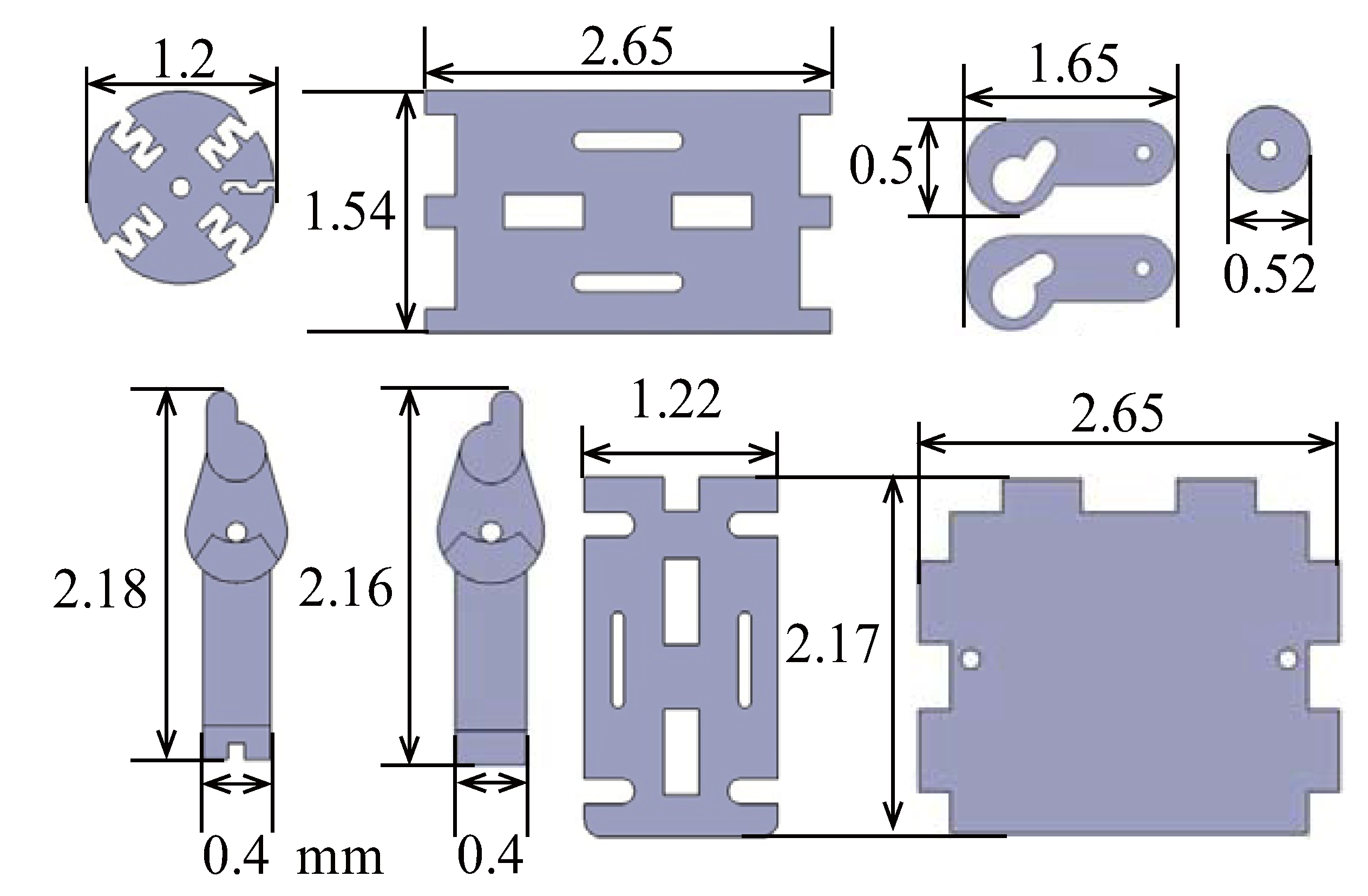
Figure 1 shows the mechanical parts of the MEMS microrobot. The fabrication of the silicon wafer was done by the micro fabrication technology. The shapes were machined by photolithography based inductively coupled plasma (ICP) dry etching [
19]. We used the 100, 200, 385, 500 μm thickness silicon wafer depending on each mechanical part.
Figure 1.
Mechanical parts of the microelectromechanical systems (MEMS) microrobot.
Figure 1.
Mechanical parts of the microelectromechanical systems (MEMS) microrobot.
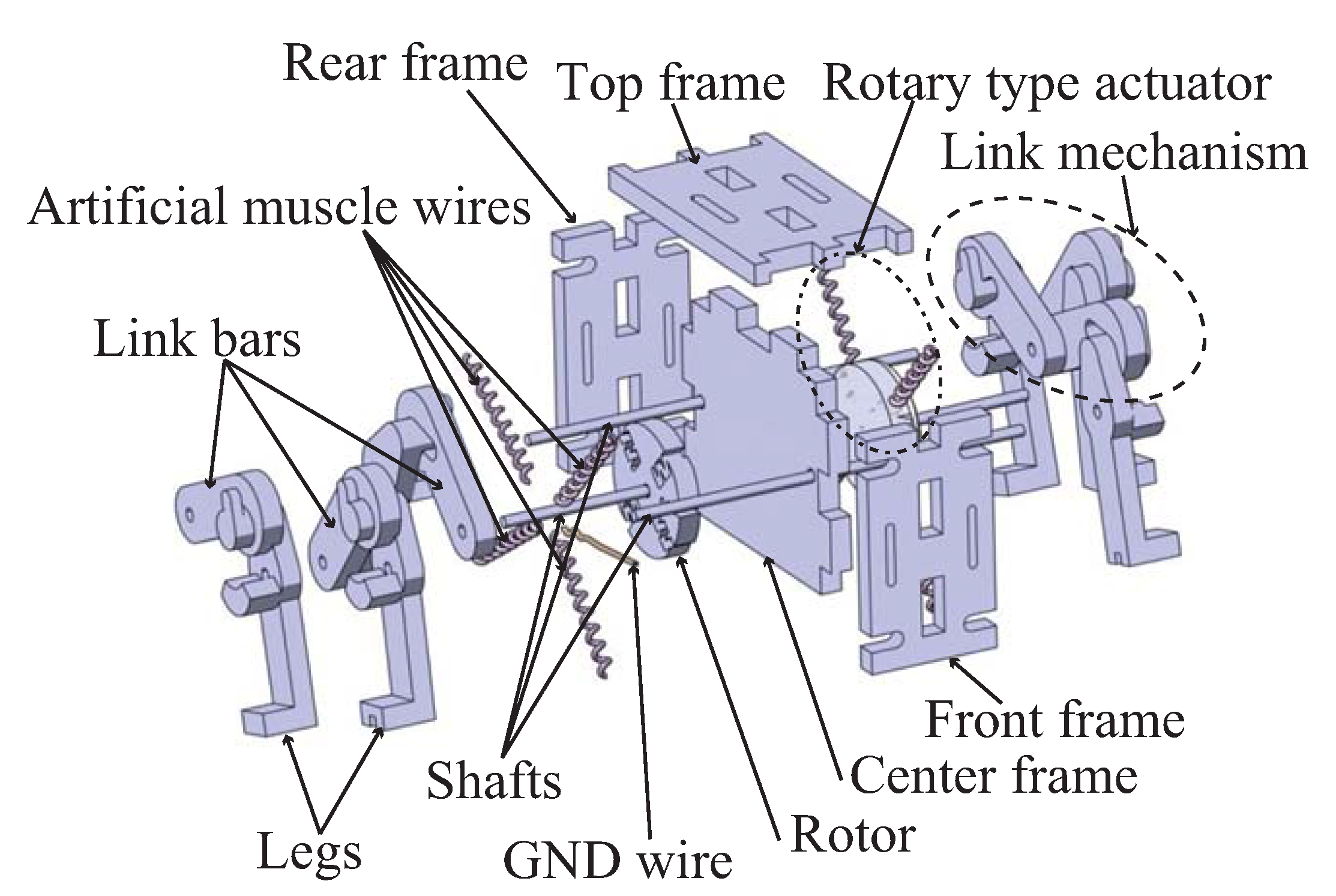
Figure 2 shows the developed figure of the MEMS microrobot. The frame components, the rotary type actuators and the link mechanism were made from silicon wafer. The frame parts consisted of a top frame, a rear frame, a front frame and a center frame. The rotary type actuators consisted of a rotor, GND wire, shaft and four pieces of helical artificial muscle wires. The rotary type actuator generated the locomotion of the robot by supplying the electrical current to the helical artificial muscle wires. The wire shrank at high temperature and extended at low temperature. In this study, the wire was heated by electrical current flowing, and cooled by stopping the flowing. The rotational movement of the each actuator was obtained by changing the flowing sequence. The link mechanisms consisted of a link bars, shafts and legs. The front leg and the rear leg were connected to the middle leg by link bars, respectively. The middle leg is connected to the rotor by the shaft. Therefore, the rotational phase was the same as the rotor. In contrast, the other two legs are connected by the link bar that generates 90° phase shift. Also, a backward step was obtained by the counter rotation of the actuator.
Figure 2.
Developed figure of the MEMS microrobot.
Figure 2.
Developed figure of the MEMS microrobot.
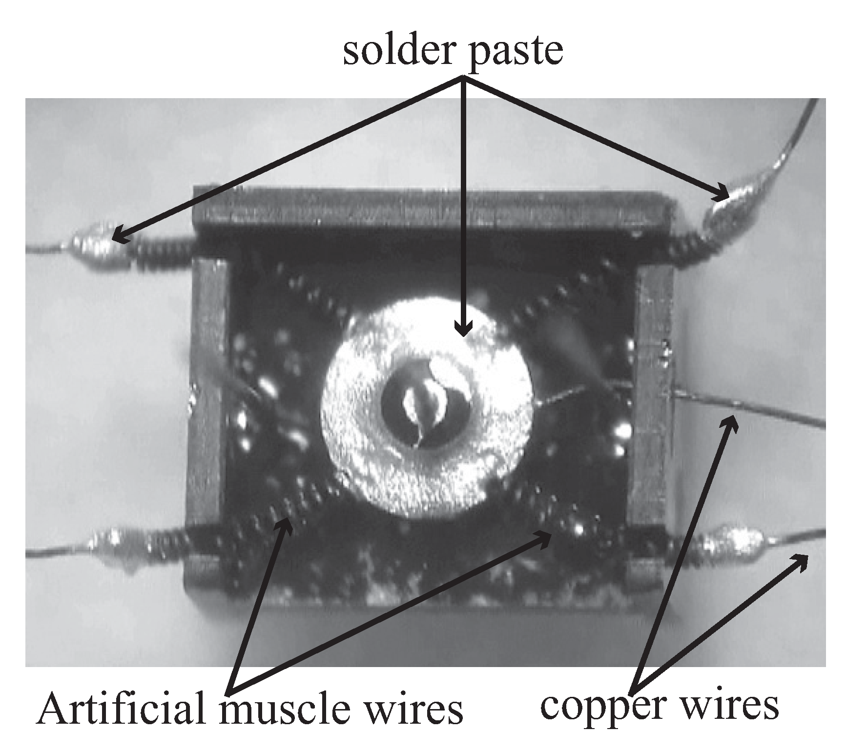
Figure 3 shows the picture of the rotary type actuator. The one side of the artificial muscle wires connected to the copper wires and the other side connected to the rotor by using solder paste. The GND wire was connected to the rotor directly. The frame components and the rotary type actuators were connected by the helical artificial muscle wire which was the shape memory alloy [
20]. We used the BioMetal
® Helix BMX50 to the helical artificial muscle wire (Available online at: [
21]). The basic characteristics of the helical artificial muscle wire were as follows. The standard coil diameter of the artificial muscle wire was 0.2 mm where wire diameter was 0.05 mm. The practical maximum force produced 3 to 5 gf where kinetic displacement was 50%. The standard drive current was 50 to 100 mA where standard electric resistance was 3600 ohm/m.
Figure 3.
Picture of the rotary type actuator.
Figure 3.
Picture of the rotary type actuator.
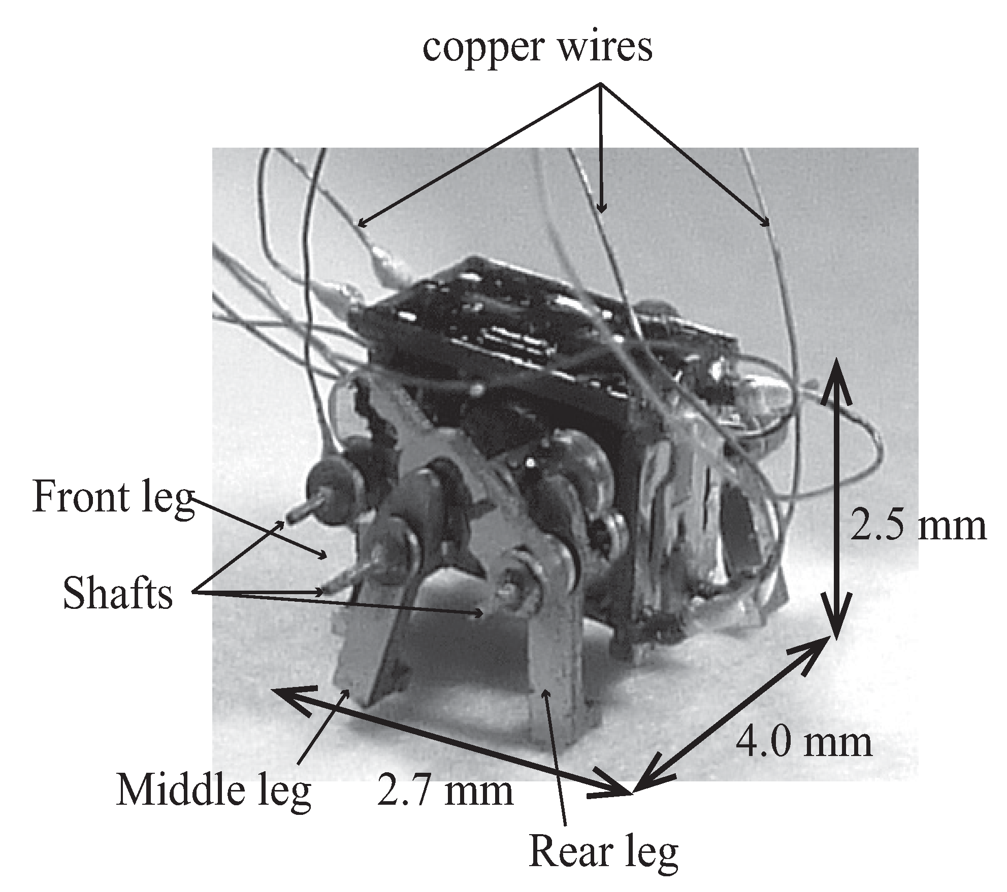
The picture of the fabricated MEMS microrobot was shown in
Figure 4. The design size was 4.0, 2.7, 2.5 mm, width, length, height, respectively. The copper wires above the MEMS microrobot were two GND wires and eight signal wires. In the case of connecting the signal wires to the NNIC, the MEMS microrobot could locomote.
Figure 4.
Picture of the fabricated MEMS microrobot.
Figure 4.
Picture of the fabricated MEMS microrobot.
2.2. Locomotion Mechanisms
Ants can locomote smoothly on the uneven surface by using step pattern. On the other hand, many microrobots were weak in moving on the uneven surface. Therefore, microrobot which could locomote by step pattern was desired. We replicate the locomotion of an ant by using rotary type actuator and link mechanism. In this section, we will discuss about locomotion mechanisms of the MEMS microrobot.
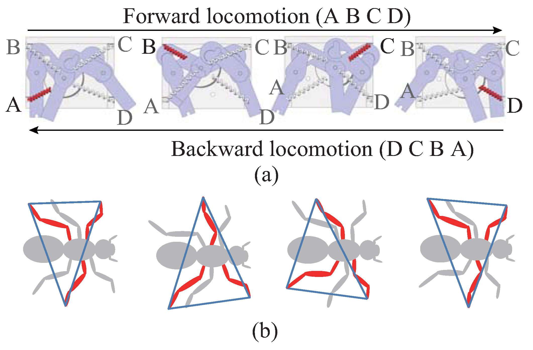
Figure 5a shows the schematic diagrams of locomotion of the MEMS microrobot. The MEMS microrobot could move by the rotational actuator. The helical artificial muscle wire had a characteristic of changing length according to temperature. In the case of heating, the wire shrunk and in the case of cooling, the wire extended. In particular, when heating the helical artificial muscle wires from A to D, the MEMS microrobot would move forward. In contrast, heating the helical artificial muscle wires from D to A, the robot moved backward. The locomotion pattern is 180° phase shift on each side to represent the locomotion of an ant. The MEMS microrobot the locomotion method of ants (see
Figure 5b. The touch with ground timing of the legs is the same.).
Figure 5.
Locomotion of the MEMS microrobot.
Figure 5.
Locomotion of the MEMS microrobot.
3. Neural Networks Integrated Circuit
It is well known that locomotion rhythms of living organisms are generated by central pattern generator (CPG). Previously, we proposed the CPG model using pulse-type hardware neuron model [
22,
23]. CPG model was board level circuit using surface-mounted components. The board level circuit was 10 cm square size. Therefore, it was impossible to integrate on the MEMS microrobot system. In addition, we proposed the packaged NNIC which could output the driving waveform of the robot. The packaged NNIC was externally connected to the robot system [
23]. Proposing NNIC can mount on the MEMS microrobot system.
Figure 6 shows the circuit diagram of pulse-type hardware neuron model. The pulse-type hardware neuron model is a basic component of the NNIC. The pulse-type hardware neuron model has the same basic features of biological neurons such as threshold, refractory period, spatio-temporal summation characteristics, and enables the generation of continuous action potentials. The pulse-type hardware neuron model consists of a synaptic model and a cell body model. In this study, we use inhibitory synaptic model as a synaptic model. The synchronization phenomena of pulse-type hardware neuron models changes by the connection of the synaptic model. The cell body model connected by excitatory synaptic model cause the in-phase synchronization. The cell body model connected by inhibitory synaptic model cause the anti-phase synchronization. Therefore, we use the inhibitory mutual coupling to generate the driving pulses which can operate the actuators of MEMS microrobot (For more detail, see Saito [
23]). The circuit parameters of synaptic model were as follows:
CES =
CIS2 = 1 pF,
MES1−3, M
IS1−5:
W/
L = 1. The voltage source
VDD = 5 V. The circuit parameters of the cell body model were as follows:
CG = 39 μF,
CM = 270 nF,
MC1,
MC2:
W/
L = 10,
MC3:
W/
L = 0.1,
MC4:
W/
L = 0.3. The voltage source
VA = 3.3 V. The input voltage
vISin of synaptic model were output voltage
vCout of the other cell body model. The input current
iCin of cell body model was output current
iISout of synaptic model.
Figure 6.
Circuit diagram of pulse-type hardware neuron model.
Figure 6.
Circuit diagram of pulse-type hardware neuron model.
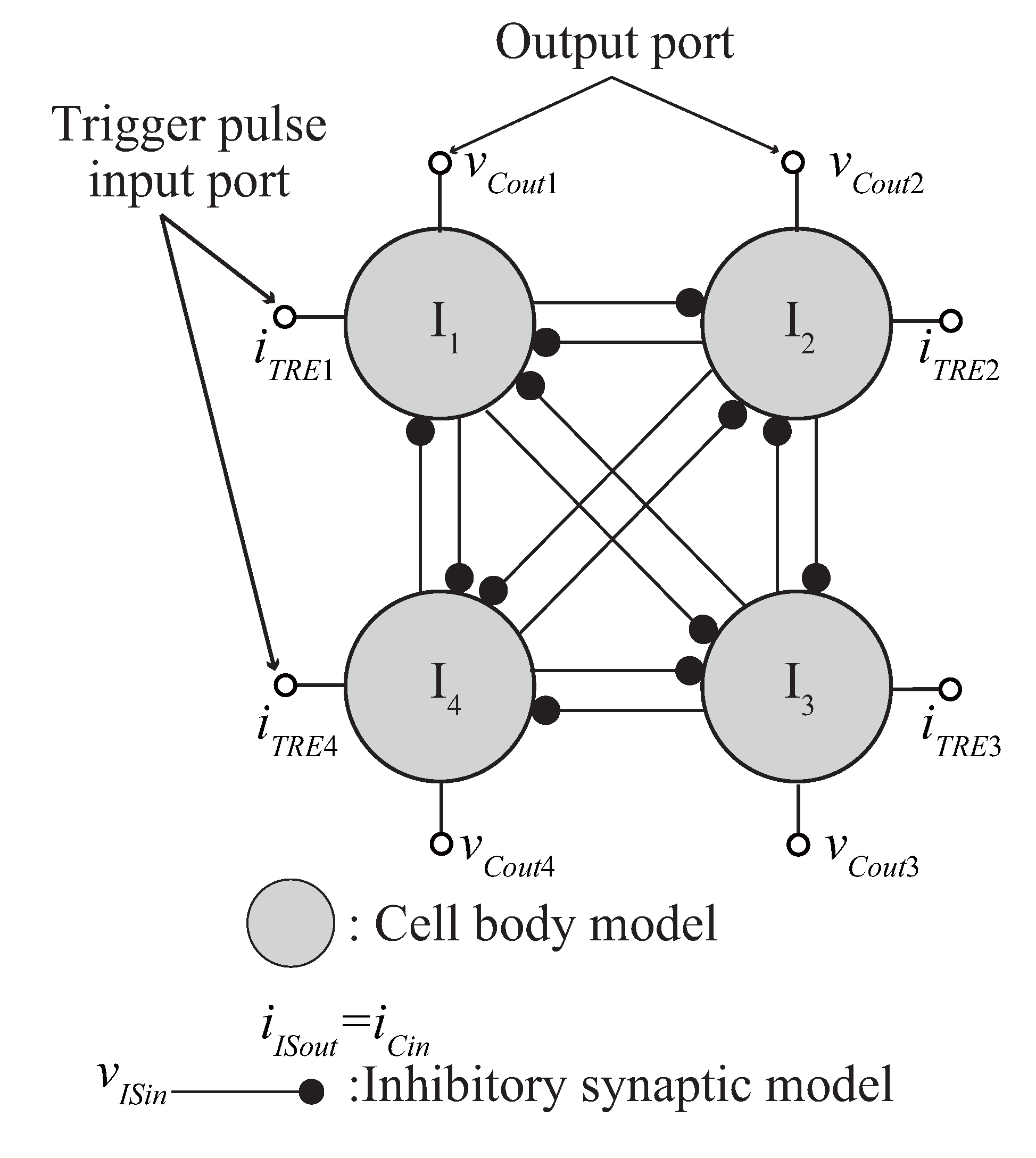
Using the anti-phase synchronization phenomena, we designed the NNIC. The connection diagram of designed NNIC was shown in
Figure 7. The four cell body models are mutually coupled by 12 inhibitory synaptic models. Four output ports were extracted from NNIC. In addition, four trigger pulse input port were extracted to NNIC. According to the input timing of single external trigger pulse, NNIC could change the sequence of driving pulses.
Figure 7.
Connection diagram of neural networks integrated circuit.
Figure 7.
Connection diagram of neural networks integrated circuit.
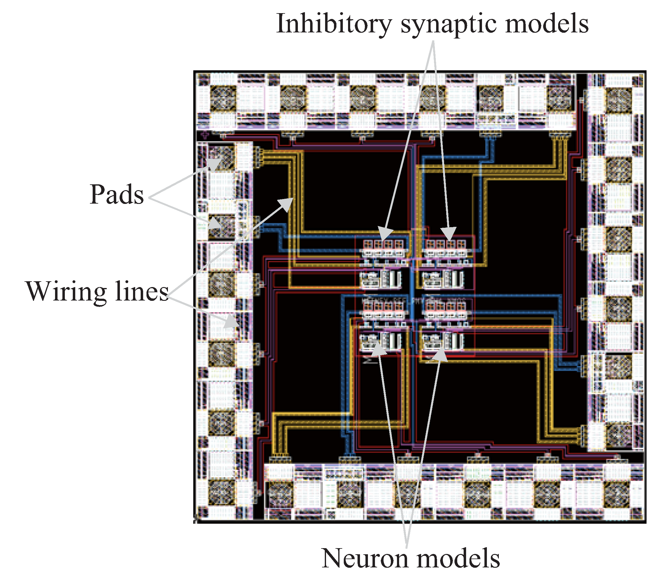
Figure 8 shows the layout pattern of NNIC. This IC chip was fabricated by Digian Technology, Inc. The design rule of the IC chip was four metal two poly CMOS 0.35 μm rule. The chip was a square 1.93 mm × 1.93 mm in size. The sizes of capacitors of cell body model are too large to implement to the CMOS IC chip. Therefore, the capacitors
CG and
CM were mounted externally of the bare chip.
Figure 8.
Layout pattern of neural networks integrated circuit.
Figure 8.
Layout pattern of neural networks integrated circuit.
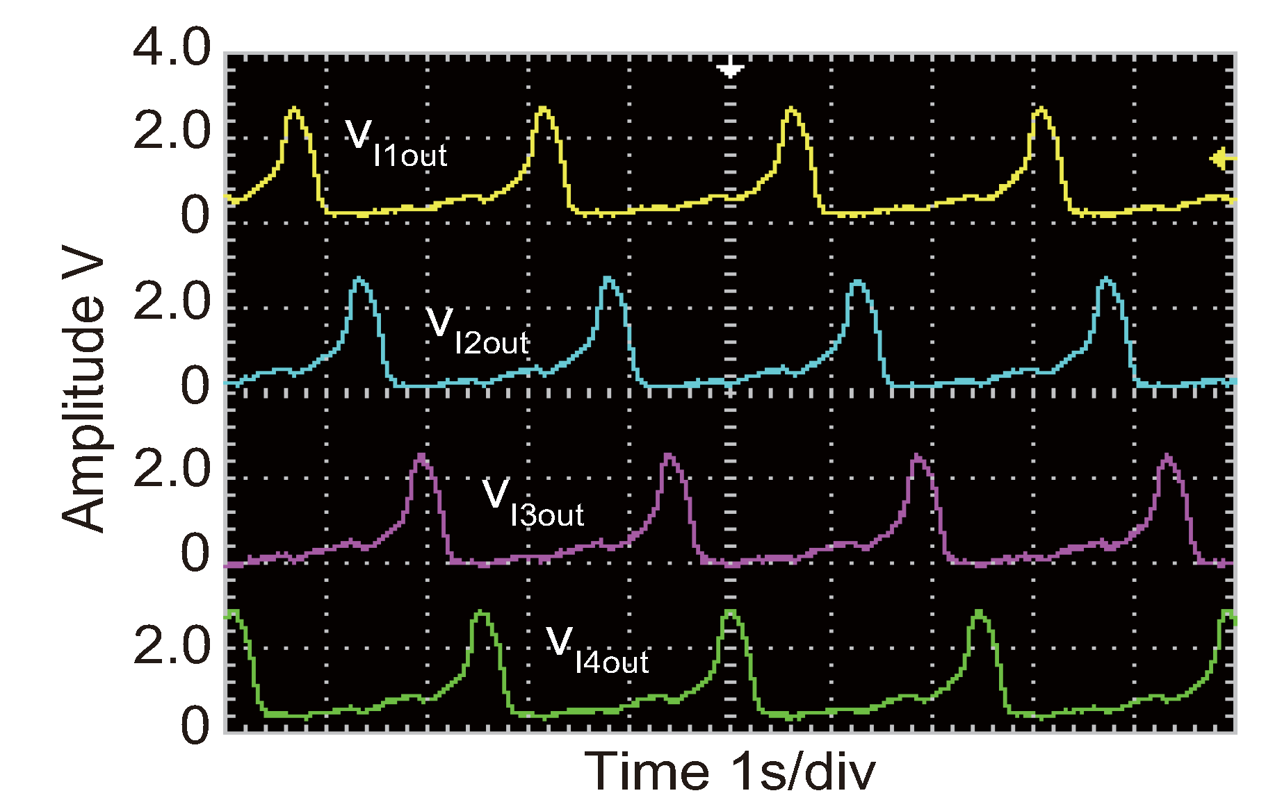
Figure 9 shows the example of output waveform of NNIC. NNIC is a coupled neural networks system which can generate the locomotion rhythms such as living organisms.
Figure 9.
Example of output waveform of neural networks integrated circuit.
Figure 9.
Example of output waveform of neural networks integrated circuit.
4. Results and Discussion
Four output ports were extracted from NNIC and they were connected to the artificial muscle wires. To heat the helical artificial muscle wires, we are required to input the pulse width 0.5 s, pulse period 2 s and pulse amplitude 2 V (such as shown in
Figure 9). Therefore, the microrobot required 2 s to finish the 1 cycle locomotion. In the case of inputting shorter than pulse width 0.5 s, the artificial muscle wire could not shrunk because the joule heat by drive current was not enough. In contrast, in the case of inputting longer than pulse width 2 s, the artificial muscle wire could not be extended because the joule heat by drive current was too much and cooling must be difficult.
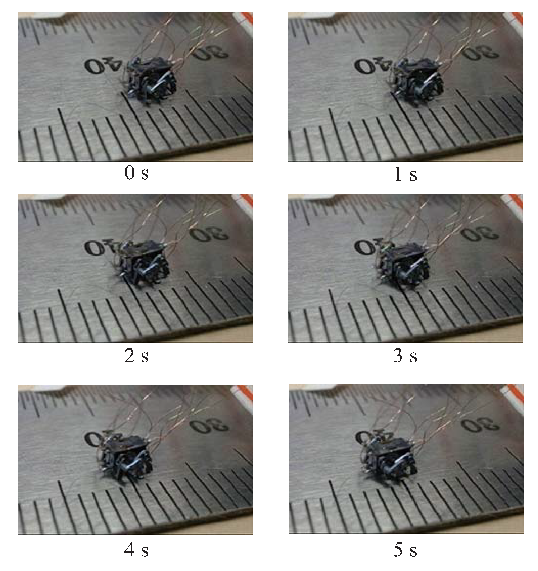
Figure 10 shows the example of locomotion of the MEMS microrobot. NNIC can output the driving pulse of locomotion which is necessary to actuate the MEMS microrobot. Thus, our NNIC is effective to generate the locomotion of the MEMS microrobot. The locomotion speed was 26.4 mm/min where the step width was 0.88 mm. (Examples of locomotion videos of MEMS microrobot are available at [
24]).
Figure 10.
Example of locomotion of the MEMS microrobot.
Figure 10.
Example of locomotion of the MEMS microrobot.
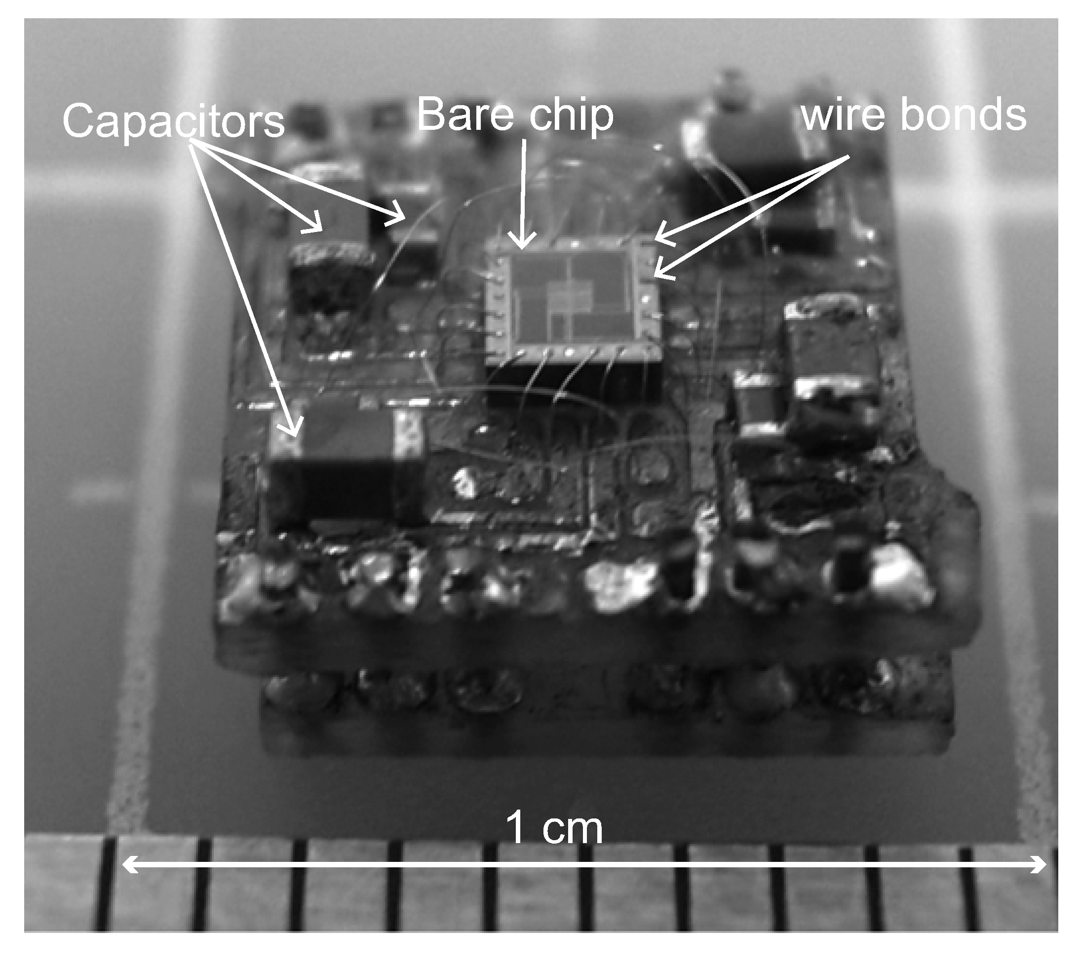
Figure 11 shows the peripheral circuit of the NNIC. The NNIC bare chip was fixed to the flame retardant type 4 (FR4) circuit board. Each pad of the NNIC bare chip was wire bonded to pad pattern of the FR4 circuit board by aluminum wire using ultrasonic wire bonding.
Figure 11.
Neural networks integrated circuit bare chip with peripheral circuit.
Figure 11.
Neural networks integrated circuit bare chip with peripheral circuit.
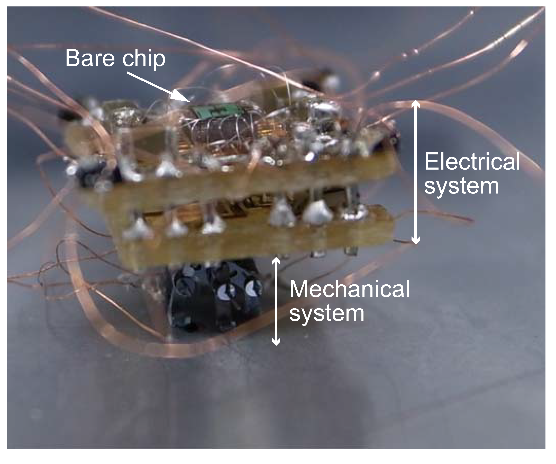
Figure 12 shows the complete system of the proposal microrobot system. The hexapod-type MEMS microrobot mounted the NNIC with peripheral circuit. The mechanical system and electrical system is connecting by enamel wire. We fix the enamel wire using solder paste.
Figure 12.
Complete system of the proposal MEMS microrobot system.
Figure 12.
Complete system of the proposal MEMS microrobot system.
5. Conclusions
In this paper, we proposed the NNIC which is the driving waveform generator of the 4.0, 2.7, 2.5 mm, width, length, height size hexapod-type microrobot system. As a result, we developed the following conclusions.
- (a)
-
Neural networks integrated circuit could output the driving pulse which is necessary to actuate the MEMS microrobot. In particular our constructed NNIC can control the movements of MEMS microrobot. The locomotion speed of MEMS microrobot was 26.4 mm/min when the step width was 0.88 mm where the room temperature of measurement environment was 298 K. The power consumption of the microrobot system was 250 mWh. Our MEMS microrobot could locomote by step pattern. Therefore, our robot could locomote more smoothly on the uneven surface compared with the other microrobot.
- (b)
-
The NNIC with peripheral circuit was fixed to the FR4 circuit board. The size of the circuit board was 9.4, 7.5 mm width, length size. The weight of the circuit board was 0.31 g.
In the future, we will construct the neural networks integrated circuit with driver circuits inside the bare chip. Consequently, we will mount the IC chip (except the capacitors) directly on the frame of the MEMS microrobot.

 ,
, 