Design Issues and in Field Tests of the New Sustainable Tractor LOCOSTRA

Abstract
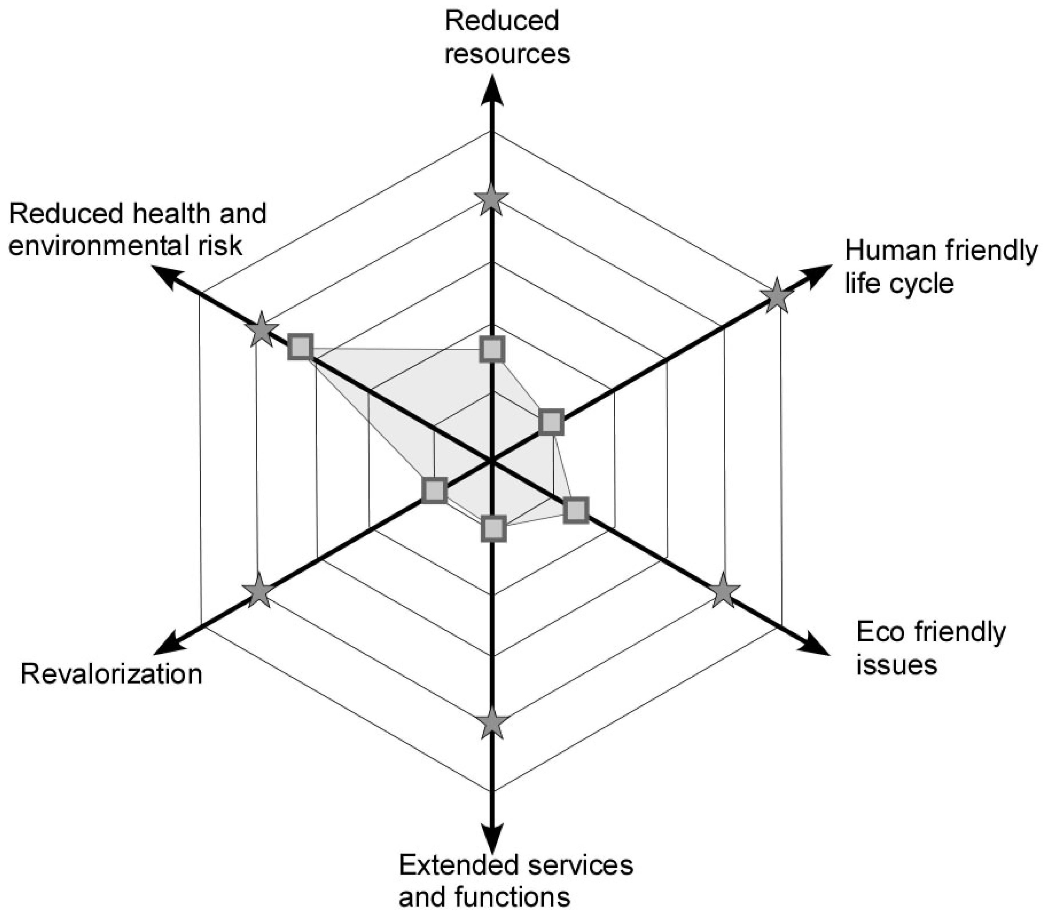
:1. Introduction
2. Mechanical Architecture and Design
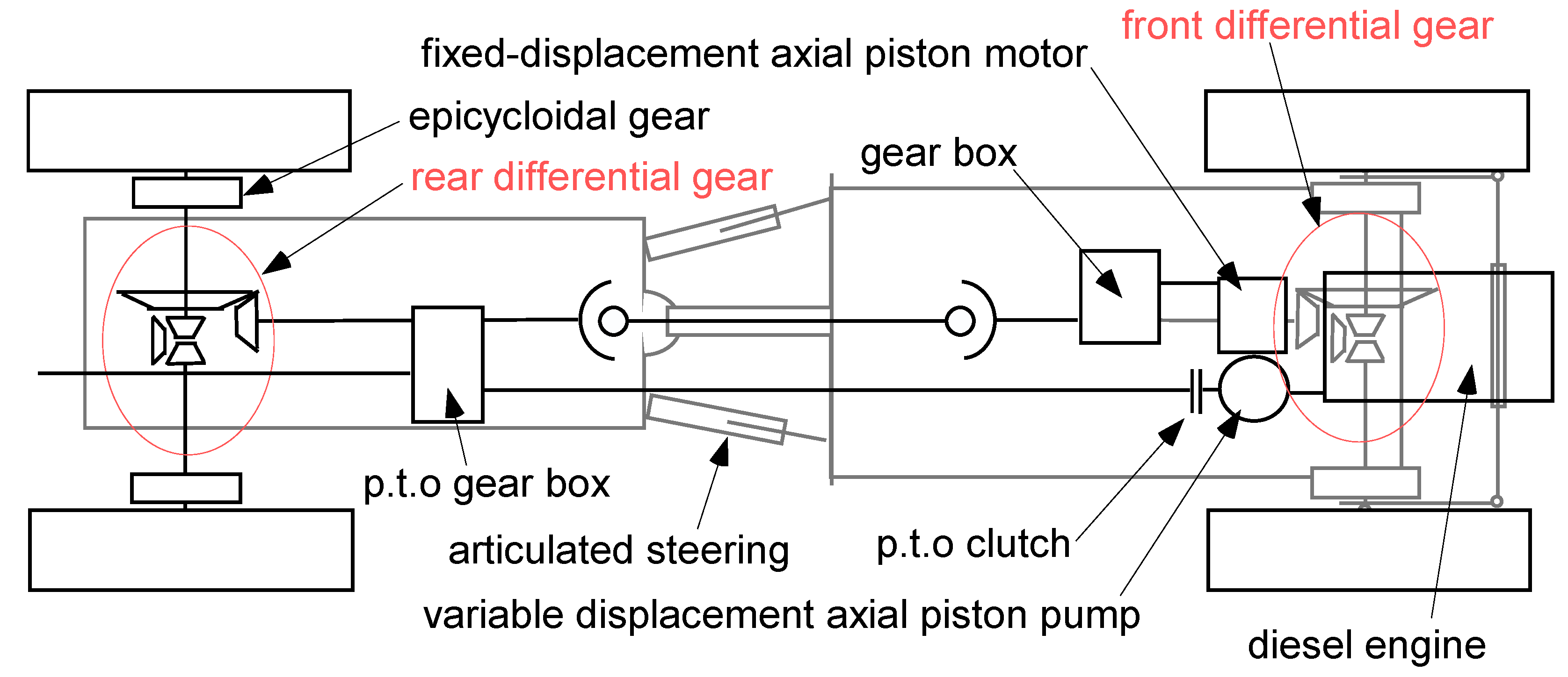
2.1. Platform Driveline and Architecture


| Length | 3.5 m | Max mass of implement | 900 kg |
| Width | 1.45 m | Armor thickness (steel plates) | 5 mm |
| Normal clearing/working width | 1.50 m | Max engine power at flywheel | 55 kW |
| Front to rear axle distance | 1.50 m | Max engine power at working tool | 48 kW |
| Inner distance between wheels on same axle | 0.95 m | Fuel capacity | 50 lt |
| Height (overall) | 2.3 m | Oil capacity | 12 lt |
| Mass (basic) | 3,100 kg | Cooling system | Water |
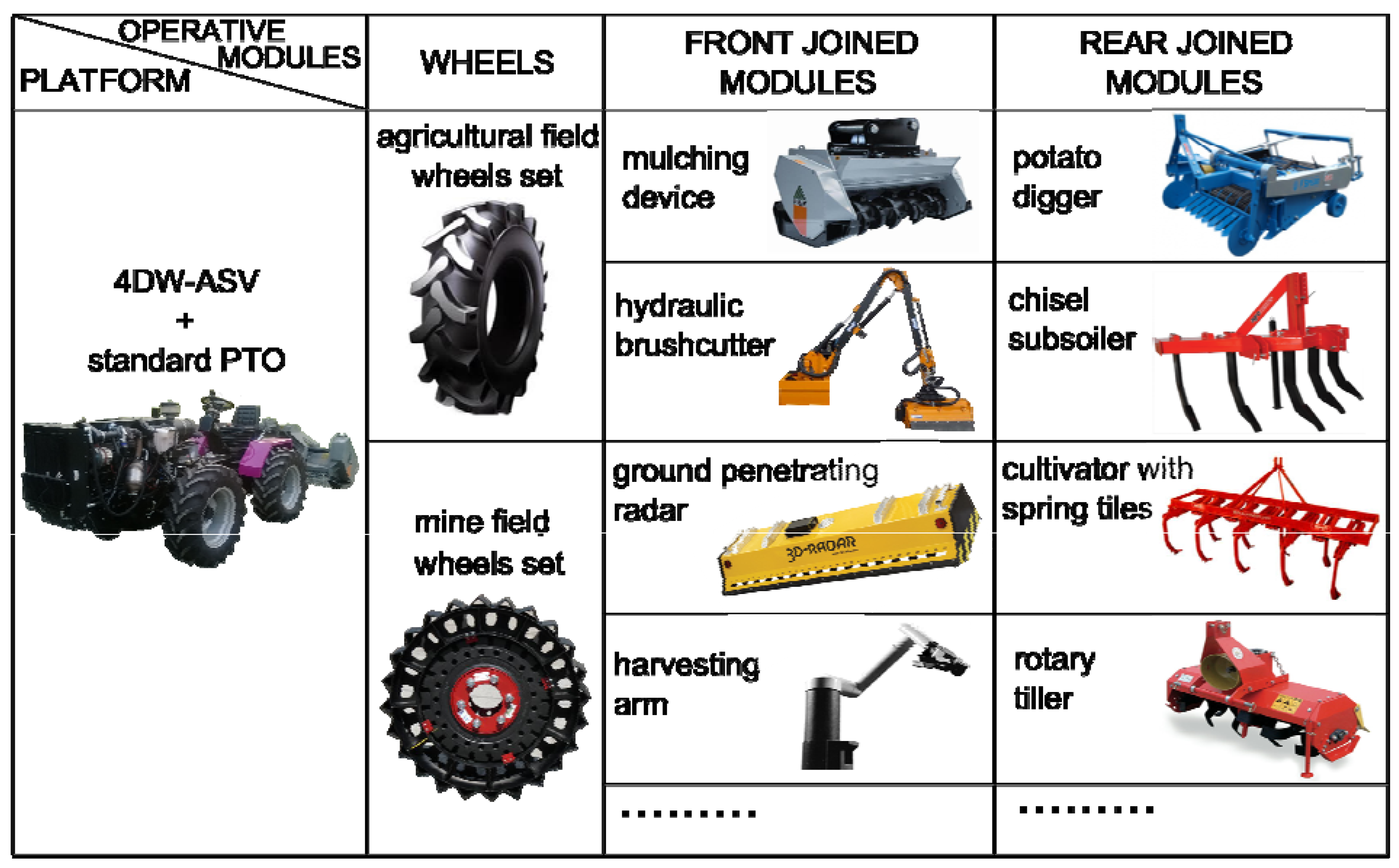
2.2. Implements
2.2.1. Standard Wheels

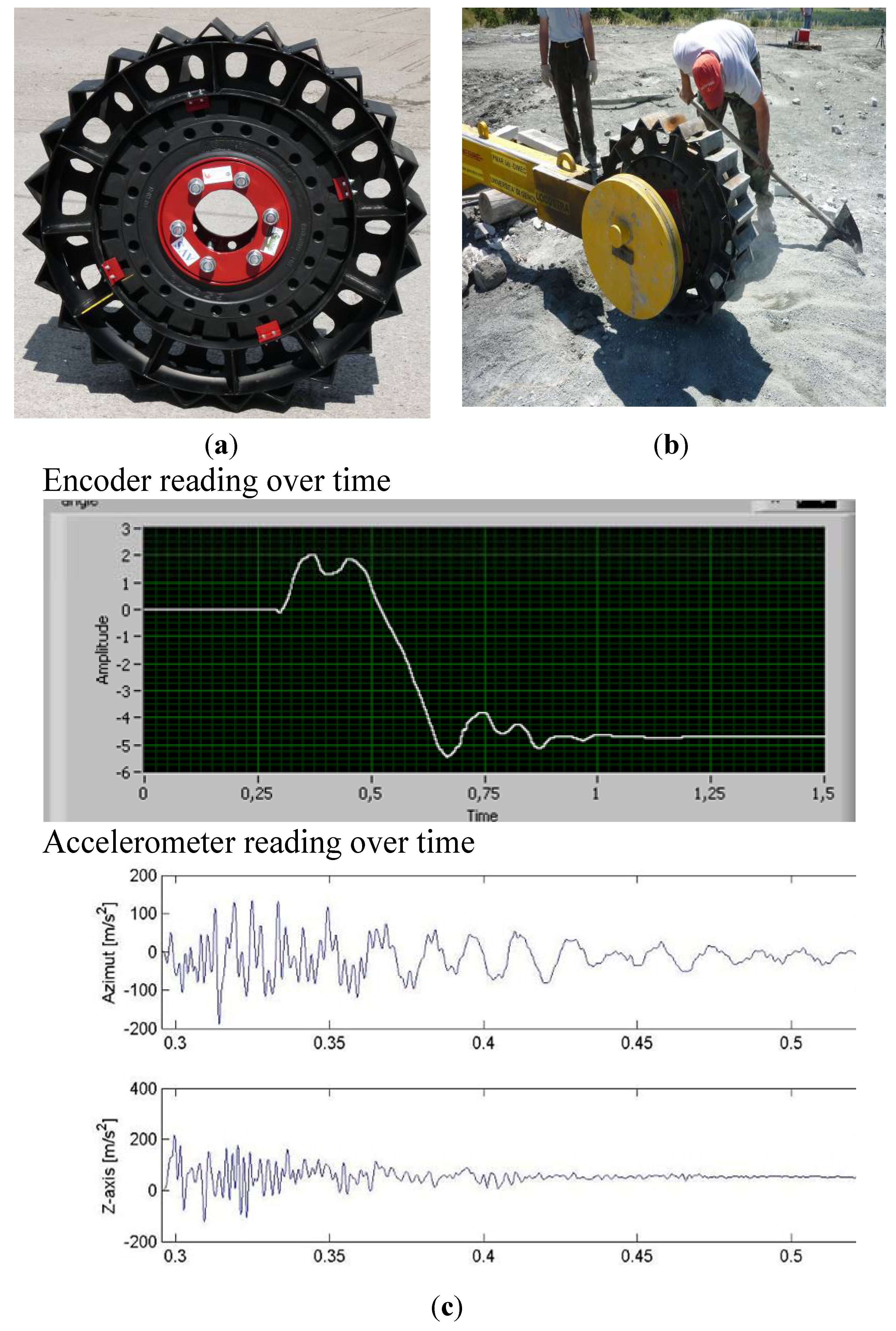
2.2.2. AP Mine Resistant Wheels

2.2.3. Vegetation Cutting Implements
2.2.4. Side-Arm Brushcutter
2.2.5. Ground Processing
3. Control System
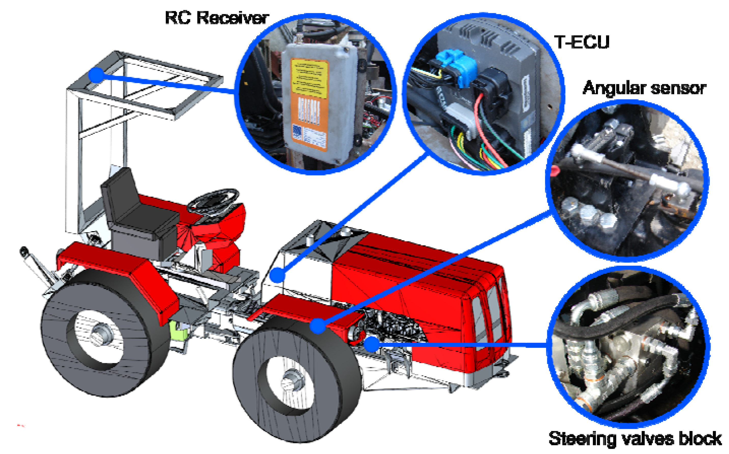
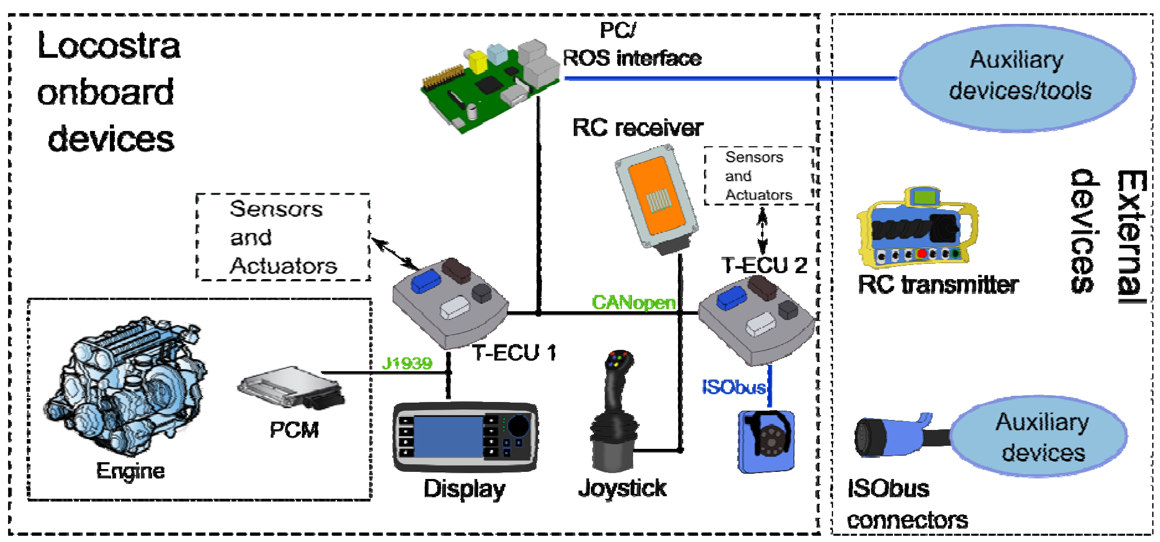
3.1. Overview


3.2. Control Modes and Human Machine Interface
3.3. Control System Features
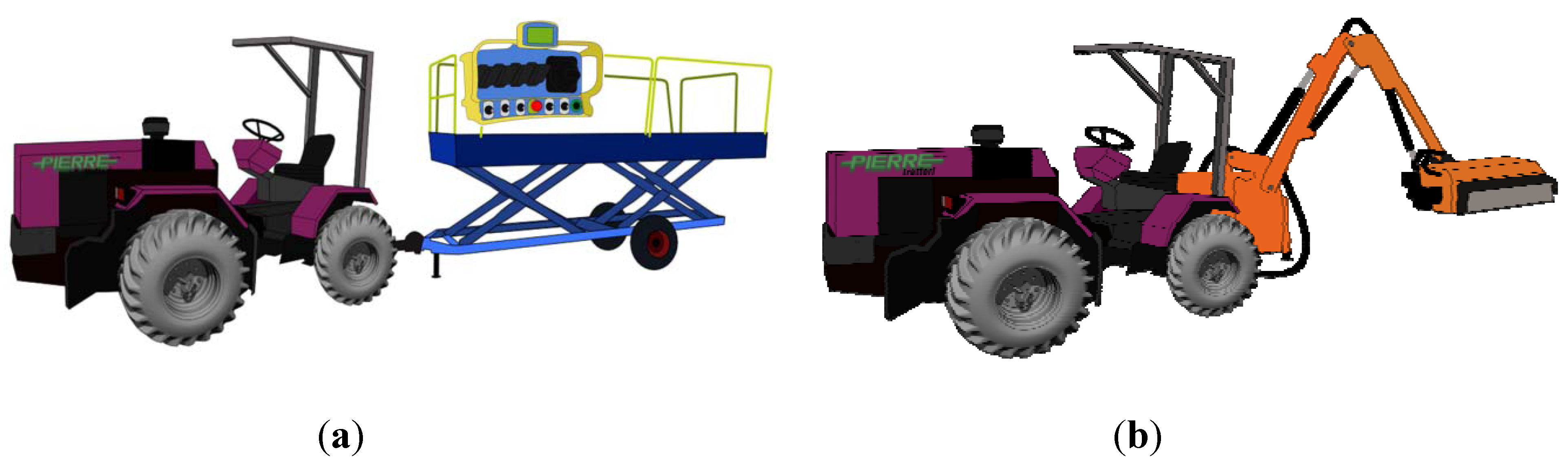
3.4. Tractor Applications


4. Field Tests
4.1. Italy in-Field Pre-Test
4.2. Jordan in-Field Test

4.3. Performance Tests
| Land Mines | Results |
|---|---|
| 11 of A10 mines were laid direct under the surface | 1. All mines removed to the surface. 2. One min was broken by the tines of the GPT. |
| 11 of M35 mines were laid at the depth of 5 cm | 1. 8 mines removed to the surface. 2. 2 mines touched and moved few centimeters of their location but stayed 5 cm under the surface. |
| 11 of M14 mines were laid at depth of 10 cm | 1. No mines were removed to the surface. 2. 6 mines were only touched by tines and remained almost at the same depth. 3. 5 mines were not touched at all. |
| Fibreboards | Results |
| Three 3 mm fiberboards with dimensions of 180 cm × 35 cm were put in the soil to give the penetration profile | All fiberboards were affected by the tines of the GPT at depth varying from 13–16 cm with average of 15 cm. |
4.4. Survivability Tests
4.5. Acceptance Tests
- Five live mines (M14) were laid at different depths between 0 and 10 cm in soft ground. Two mines were passed over by the wheels and three ones were processed by the GPT.
- Two live mines (M35) were laid in a safe area and passed over by the wheels. The test was repeated in an active mine field containing mines of type PMN (containing 240 g of TNT explosive).
- Two days of tests using the mulcher on suspected hazardous areas covered by medium and tall vegetation in the Jordan Valley.
| Activities | Results |
|---|---|
| One live M14 (28 g) was laid at depth of 5cm to be activated by the rear wheel | (1). The mine was activated.
(2). No damage reported. |
| One live M14 (28 g) was laid at depth of 5cm to be activated by the front wheel | (1). The mine was not activated. |
| Two live M14 were laid to be processed by the GPT. One of them was lad directly under the surface and one was laid at depth of 10 cm | (1). One mine was removed to the surface.
(2). One mine exploded under the wheel of the GPT. |
| Two live M35 (100 g) were laid, the first one was laid on the surface one meter from the front wheel, the second mine was laid one meter from the rear wheel at 5cm depth. Wheels past over the mines | (1). The first mine was activated, no damage to the wheel was reported.
(2). The second mine was not activated. The mine was removed out by the GPT and it was found pressed down and cracked. |
| Two live PMN (240 g) were laid, the first one was laid on the surface one meter from the front wheel, the second mine was laid one meter from the rear wheel at 5 cm depth. Wheels past over the mines | (1). The first mine was activated, only light damage was caused to the wheel.
(2). The second mine was not activated, it was disposed by another mine. |
5. Conclusions
Acknowledgments
Authors Contributions
Conflicts of Interest
References
- Acaccia, G.M.; Michelini, R.C.; Molfino, R.M.; Razzoli, R.P. Mobile Robots in Greenhouse Cultivation: Inspection and Treatment of Plants. In Proceedings of the 1st International Workshop Advanced in Service Robot, Bardolino, Italy, 13–15 March 2003.
- Kondo, N.; Morita, M.; Noguchi, N. Agricultural Robots: Mechanisms and Practice; Trans Pacific Press: Melbourne, Australia, 2011; pp. 1–360. [Google Scholar]
- Yukumoto, O.; Matsuo, Y.; Noguchi, N. Robotization of agricultural vehicles (Part 1). Jpn. Agri. Res. Q. 2000, 34, 99–105. [Google Scholar]
- Yukumoto, O.; Matsuo, Y.; Noguchi, N. Robotization of agricultural vehicles (Part 2). Jpn. Agri. Res. Q. 2000, 34, 107–114. [Google Scholar]
- Matsuo, Y.; Yukumoto, O.; Yamamoto, S.; Noguchi, N.; Hara, Y. Review enhanced adaptability of tilling robot (2nd report)—Execution of various operations by tilling robot. Jpn. Agri. Res. Q. 2013, 47, 153–164. [Google Scholar] [CrossRef]
- Ismail, W.I.W.; Hudzari, R.M.; Saufi, M.K.M.; Fung, L.T. Computer-controlled system for autonomous tractor in agricultural application. J. Food Agri. Environ. 2012, 10, 350–356. [Google Scholar]
- Cepolina, E.E. Power tillers and snails for demining in Sri Lanka. J. Mine Action 2006, 10, 76–79. [Google Scholar]
- Dixon, R. A Concept of Implementing Technology to Encourage Economic Growth in Demining. In Proceedings of the International Workshop on Robotics and Mechanical Assistance in Humanitarian Demining and Similarly Risky Interventions, Brussels, Belgium, 16–18 June 2004.
- Bottomley, R. Returning Life to Field and Forest: Demining by Villagers in Cambodia. Available online: http://www.jmu.edu/cisr/journal/5.1/Focus/Ruth_Bottom/bottom.html (accessed on 10 March 2014).
- Knight, P.; Jenkins, J.O. Adopting and applying eco-design techniques: A practitioners perspective. J. Clean. Prod. 2009, 17, 549–558. [Google Scholar] [CrossRef] [Green Version]
- Cepolina, E.E.; Zoppi, M. Could local agricultural machines make a country “impact free” by 2010? Int. J. ERW Mine Action 2009, 13, 47–52. [Google Scholar]
- Rovira-Más, F. Sensor Architecture and task classification for agricultural vehicles and environments. Sensors 2010, 10, 11226–11247. [Google Scholar] [CrossRef]
- Delhay, S.; Lacroix, V.; Idrissa, M. PARADIS: Focusing on GIS Field Tools for Humanitarian Demining. In Proceedings of the Fifth IARP WS HUDEM, Brussels, Belgium, 16–18 June 2004.
- Horton, D.N.L.; Crolla, D.A. Theoretical analysis of the steering behaviour of articulated frame steer vehicles. Veh. Syst. Dyn. 1986, 15, 211–234. [Google Scholar] [CrossRef]
- Crolla, D.A.; El-razaz, A.S.A. A review of the combined lateral force generation of tires on deformable surfaces. J. Terramechanics 1987, 24, 199–225. [Google Scholar] [CrossRef]
- Gee-Clough, D.; Sommer, M.S. Steering forces on undriven, angled wheels. J. Terramechanics 1981, 18, 25–49. [Google Scholar] [CrossRef]
- Metz, L.D. Dynamics of four-wheel-steer off-highway vehicles. SAE Paper 1993. [Google Scholar] [CrossRef]
- Iida, M.; Fukuta, M.; Tomiyama, H. Measurement and analysis of side slip angle of articulated vehicle. Eng. Agric. Environ. Food 2010, 3, 1–6. [Google Scholar] [CrossRef]
- Azad, N.L.; Khajepour, A.; Mcphee, J. Robust state feedback stabilization of articulated steer vehicles. Veh. Syst. Dyn. 2007, 45, 249–275. [Google Scholar] [CrossRef]
- Bekker, M.G. Off-the-Road Locomotion, Research and Development in Terramechanics; University of Michigan Press: Ann Arbor, MI, USA, 1960. [Google Scholar]
- Cepolina, E.E.; Zoppi, M.; Belotti, V. Locostra: Blast-resistant wheels test. Int. J. ERW Mine Action 2011, 15, 75–81. [Google Scholar]
- Naselli, G.A.; Polentes, G.; Cepolina, E.E.; Zoppi, M. A simple procedure for designing blast resistant wheels. Procedia Eng. 2013, 64, 1543–1551. [Google Scholar] [CrossRef]
- Przybyłko, M.; Cepolina, E.E.; Zoppi, M.; Polentes, G. A Robust, Simple, Low-Cost Autonomy Enhancement Module for Locostra: A Remotely Controlled Demining Machine. In Proceedings of the 9th International Symposium HUDEM 2012, Sibenik, Croatia, 24–26 April 2012.
- Livatino, S.; Muscato, G.; Sessa, S.; Koffel, C.; Arena, C.; Pennisi, A.; Di Mauro, D.; Malkondu, E. Depth-enhanced mobile robot teleguide based on video images. IEEE Robot. Automa. Mag. 2008, 15, 58–67. [Google Scholar]
© 2014 by the authors; licensee MDPI, Basel, Switzerland. This article is an open access article distributed under the terms and conditions of the Creative Commons Attribution license (http://creativecommons.org/licenses/by/3.0/).
Share and Cite
Cepolina, E.E.; Przybyłko, M.; Polentes, G.B.; Zoppi, M. Design Issues and in Field Tests of the New Sustainable Tractor LOCOSTRA. Robotics 2014, 3, 83-105. https://doi.org/10.3390/robotics3010083
Cepolina EE, Przybyłko M, Polentes GB, Zoppi M. Design Issues and in Field Tests of the New Sustainable Tractor LOCOSTRA. Robotics. 2014; 3(1):83-105. https://doi.org/10.3390/robotics3010083
Chicago/Turabian StyleCepolina, Emanuela Elisa, Michał Przybyłko, Giovanni Battista Polentes, and Matteo Zoppi. 2014. "Design Issues and in Field Tests of the New Sustainable Tractor LOCOSTRA" Robotics 3, no. 1: 83-105. https://doi.org/10.3390/robotics3010083