Effect of Link Misalignment in the Optical-Internet of Underwater Things
by
 , , ,
, , ,
Ruhul Amin Khalil
1 ,
,
Mohammad Inayatullah Babar
1 ,
,
Nasir Saeed
2 ,
,
Tariqullah Jan
1 and
Ho-Shin Cho
3,*
1
Department of Electrical Engineering, Faculty of Electrical and Computer Engineering, University of Engineering and Technology, Peshawar 25120, Pakistan
2
Computer, Electrical, and Mathematical Sciences & Engineering (CEMSE) Division, King Abdullah University of Science and Technology, Thuwal 23955, Saudi Arabia
3
School of Electronics Engineering, Kyungpook National University, Daegu 41566, Korea
*
Author to whom correspondence should be addressed.
Electronics 2020, 9(4), 646; https://doi.org/10.3390/electronics9040646
Submission received: 13 March 2020
/
Revised: 2 April 2020
/
Accepted: 11 April 2020
/
Published: 15 April 2020
(This article belongs to the Special Issue Underwater Communication and Networking Systems)
Abstract
:Underwater wireless optical communication (UWOC) enables high-speed links in water for the optical Internet of Underwater Things (O-IoUT) networks. O-IoUT provides various marine applications, including ocean exploration, environmental monitoring, and underwater navigation. O-IoUT typically utilizes light-emitting diodes (LEDs) and different laser diodes (LDs) such as green/blue lasers to achieve efficient data communication in the underwater environment. The high-speed optical communication is limited up to a few tens of meters due to underwater channel impairments and misalignment between the transmitter (Tx) and the receiver (Rx). UWOC provides high-speed communications only in the line of sight conditions, and a small misalignment between the Tx and the Rx can degrade the system performance. In an attempt to understand and minimize this misalignment issue, we investigate how received power in a UWOC system depends on the transmitted beam’s divergence angle. Simulation results are provided to show the effectiveness of the study by comparing the plane, Gaussian, and spherical beams. Monte Carlo simulations are utilized to determine the maximum allowable lateral offset between Tx and Rx for a given Tx divergence angle. The results provide an overview and design-based trade-off between different parameters such as lateral offset, the power received, and bandwidth of the channel. The proposed method improves not only the maximum allowed link-span but also the bandwidth of the channel for a given transmission distance.
1. Introduction
The requirement of high-speed wireless communications in the marine environment has led to the development of optical internet of underwater things (O-IoUT) [1,2]. The O-IoUT uses optical waves as carriers for data transmission in marine environments to enable a large number of applications that include maritime archeology, tracking of marine species, communication between off-shore ships with underwater divers and submarines for navigation, search and rescue purpose [3]. The O-IoUT usually uses green/blue laser beams due to their low absorption in water and to obtain high-speed data communication for more considerable distances. The problem arises when this transmission encounters misalignment between the transmitter (Tx) and receiver (Rx). In the literature, many techniques have been presented to resolve this issue but are not so effective due to their complex structure and time-costly application [4].
The development of O-IoUT can be used for autonomous data collection for large-scale complex underwater systems [5]. It can enable multiple marine applications such as environmental monitoring, ocean exploration, sea surface monitoring, and underwater habitat monitoring. Recently, some new developments for implementing O-IoUT are based on programmable marine sensing devices, networking virtualization, and underwater software-defined networking [6]. Apart from that, the IoUT devices will be able enough to work effectively for a multimodal underwater communication that includes magnetic induction and acoustic waves.
Underwater wireless communication (UWC) systems use different communication technologies, such as acoustic waves, radio frequency (RF) waves, and optical waves [7]. The RF waves and acoustics waves are vastly used for omnidirectional underwater communications [8]. However, the optical carrier waves offer some distinctive data transmission features and properties as compared to RF and acoustic waves [9]. RF transmission links often operate at low frequencies (30 Hz to 30 kHz) due to the high absorption of electromagnetic waves in seawater [10]. Larger antennas are not generally utilized because of higher powers. However, larger antennas are generally used at lower frequencies to maintain a relatively narrow beam width. Similarly, the acoustic waves in the underwater environment provide data transmission up to several hundred kilometers, but its data rate is low [11]. In comparison with acoustic and RF waves, the underwater wireless optical communications (UWOC) provides high data transmission rate usually in Gbps, but can only travel for distances up to a few meters. Due to its simple employment and cost-efficient architecture, the UWOC systems are desirable for a large scale underwater environment [12].
The performance of the O-IoUT is affected by various factors such as absorption and multiple scattering of the propagating optical beams (depends upon ) in an underwater environment. Absorption of optical beams is irreversible in water and leads to the reduced intensity of the received signal. According to [13], the wavelength is expressed in term of spectral coefficient of absorption of light , and spectral coefficient of deflection of light from its defined path . The deviation commonly results in the scattering of light that further leads to dispersion in time and its associated inter-symbol-interference (ISI). These impediments decrease the signal-to-noise (SNR) of the received signal and therefore increase the overall bit-error-rate (BER) of the defined communication system. Various techniques such as optical pre-amplification and spatial diversity can be utilized for the improvement of both the BER and SNR [14], but the turbid nature of the underwater limits the BER performance improvement and high data rate transmission [15,16]. Therefore, the parameters for absorption and scattering are of very much importance during the design and implementation of UWOC systems.
Besides the problem of absorption and scattering, optical waves in O-IoUT require line-of-sight links where the misalignment between the Tx and the Rx significantly reduces the data rate and effect BER performance. The contributions of the paper are summarized as follows:
- First, we investigate the misalignment between Tx and Rx for a single-input-single-output (SISO) O-IoUT system by considering various optical beams such as Plane, Gaussian, and Spherical.
- Then, we analyze the effect of divergence angle for all these beams in the presence of link misalignment.
- Furthermore, we derive the BER expression for the O-IoUT link when there is a misalignment between the Tx and the Rx.
- Lastly, the proposed approach for link misalignment in O-IoUT has been evaluated based on normalized received power, maximum acceptable literal offset (MALO), and BER performance.
The rest of the paper is structured as follows. Section 2 provides a brief survey of the related work and presents the requirements and main challenges encountered by the O-IoUT networks. Section 3 elaborates the proposed system model with studying the effect of misalignment on the underwater optical link in O-IoUT. Section 4 provides the BER analysis for link misalignment using the proposed approach. In Section 5, conclusions are made followed by future directions.
2. Related Work
2.1. Literature on O-IoUT
The absorption and scattering of light in seawater reduce the performance of the UWOC links in providing high data transmission in O-IoUT. Therefore, the effect of absorption and scattering for UWOC is widely studied in the literature. For example, in [17] the authors have presented a Monte Carlo simulations-based model for self-directed underwater vehicles. Further, the channel impulse response for UWOC has been demonstrated utilizing double gamma function. Moreover, the effect of random surface wind on the UWOC link is investigated in [18], which causes severe degradation to the BER.
The impulse response of the channel for a multiple-input-multiple-output (MIMO) and its effects on the underwater communication link are considered in [19]. In [20], the authors provided simulations for networking in laser-based underwater communication systems. They also investigated the impact of vertical buoy-based and its pointing errors for effective underwater communication. According to [21,22], most of the previous works used red/green laser light for the development of a UWOC system and analyzed its performance based on the angle of divergence. In [23], the authors also considered other performance parameters such as spatial diversity and multi-pulse position modulation, inter-symbol interference (ISI), and noise produced by the oceanic turbulence.
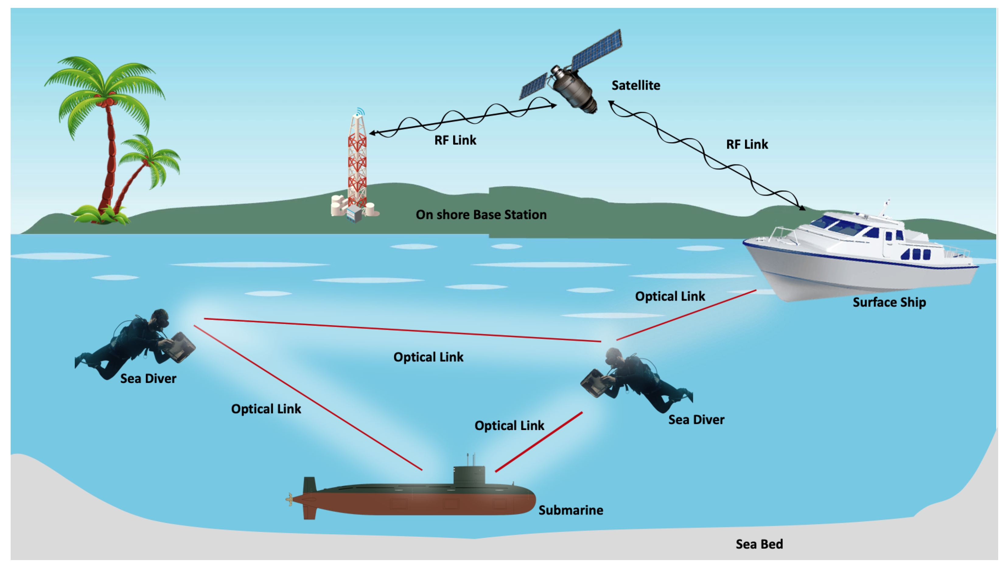
Besides other impediments, modeling of the misalignment between the Tx and the Rx is an essential factor for effective underwater communication because the UWOC link is affected by the highly scattering phenomena. In general, the optical source used in the UWOC system has a narrow divergence angle and follows line-of-sight (LOS) transmission mode, as shown in Figure 1. The LOS formation requires smart alignment and precise synchronization between the Tx and the Rx [24]. However, factors such as the harsh and turbid nature of ocean water, wind disturbance at the surface, and random movement of the water cause misalignment between the Tx and the Rx. This leads to disturbance in LOS links, loss in information, low SNR, high BER, and pulse broadening for the small field-of-view (FOV) of the Photo-Detector (PD).
One of the most crucial aspects of UWOC is to examine the respective divergence beam of the Tx in the marine environment. Several works in the literature discuss the link misalignment issue for free-space optical (FSO) communication. For instance, the authors in [25] proposed a method for avoiding link misalignment in terrestrial optical wireless networks. Consequently, in [26], the authors tackled the issue of pointing errors in the FSO communication system to prevent optical turbulence. Similarly, in [27], performance of the FSO communication link over slow fading channel is investigated, considering various parameters such as detector size, beam width, and jitter. Nevertheless, in [28], the authors examined both the pointing error and misalignment issues for the FSO communication system. These techniques work well in terrestrial networks; however, implementing them in the underwater environment is more challenging. For example, the authors in [29] performed statistical studies regarding the fading issue in UWOC, including the air bubbles, salinity, and temperature. Similarly, the authors in [30] developed a UWOC channel model in the presence of blockage and shadowing. Moreover, in [31], the issue of misalignment for a UWOC link is investigated by using the Gaussian beam only. To the best of the author’s knowledge, no previous works studied the misalignment issue using the plane, Gaussian, and spherical beams for O-IoUT networks. Therefore, in this paper, an increase in the angle of divergence for a transmitted plane, Gaussian and spherical beams is considered for reducing the link sensitivity to misalignment. In [32], the authors briefly discussed the misalignment using LDs as a source, and analyzed various parameters such as normalized transmitted power, defined link-span, and distance to the Rx. The angle-of-elevation (AOE) and FOV of the Rx usually gets affected by the link misalignment. Also, when the AOE and the divergence angle for a point source are disturbed, it leads to a reduction in the received power [33]. In the literature, many solutions have been proposed to tackle the misalignment between the Tx and the Rx for performance improvement. These solutions include various modalities such as active tracking, utilization of wide-area PDs, and multi-array PDs to avoid link misalignment.
A summary of few channel modeling techniques for UWOC along with their merits and shortcomings are given in Table 1.
2.2. O-IoUT: Requirements and Challenges
The propagation of light in the underwater environment is not the same for different depths and locations due to variations in absorption and scattering. In particular, the O-IoUT faces various challenges such as absorption, scattering, multi-path fading, and misalignment. In the following, we discuss each of these challenges in the context of O-IoUT.
2.2.1. Absorption and Scattering
The first challenge encounter by O-IoUT is the absorption and scattering of light during underwater propagation that limit its transmission range. According to [49], the radiance and reflectance of optical light in underwater environment are determined by analyzing its geometrical properties. Also, absorption and scattering of photons reduce the energy of optical beams during underwater propagation. When the photons are scattered in various directions, it leads to improper data reception at the Rx due to its limited FOV. The absorption and scattering also result in other unwanted phenomena, such as time-jitter, inter-symbol interference (ISI), and multi-path fading.
2.2.2. Multi-path fading and Time Jitter
The multi-path fading and delay spread in O-IoUT occurs due to intense reflection of the optical beam after striking with water particles and other obstacles before reaching the center of Rx aperture [50]. This leads to reception of the optical beam at various time instants, and hence, results in ISI. For quantification of these issues, the authors in [50] investigate these performance degradation factors by analyzing the angle of divergence using polarized optical beam. We have tried to consider the same angle of divergence, but with three different optical beams such as plane, Gaussian, and spherical, simultaneously. We then utilized Monte Carlo simulations for channel description and analyze the time spreading that is approximately negligible for short distances in an O-IoUT.
2.2.3. Pointing and Link Misalignment
Another challenge faced by O-IoUT is to maintain proper pointing and alignment of the optical Tx and Rx. These two phenomena usually occur as a result of bore-sighting and jittering as provided in [51]. The bore-sight refers to a fixed shifting from a defined optical transmission trajectory toward the center of Rx antenna aperture that leads to inaccurate reception. In contrast, jitter is caused by ocean turbulence and deep oceanic variations between the optical beam and center of Rx aperture [52,53].
In this paper, we investigate the variance in divergence angle of a transmitted plane, Gaussian, and spherical beams to optimize the normalized received power in a UWOC system. Also, a proper trade-off is defined between the narrow and wide divergence angles. For example, a narrow beam can provide a more directive long-range link but requires accurate pointing of Tx and Rx. On the other hand, a wider beam provides short-range links but does not require tight pointing and acquisition. Therefore, in this paper a trade-off is made between various system parameters such as maximum acceptable lateral offset (MALO) of the Rx and angle of divergence. The effect of loss in received power, and BER analysis for variable link distance are also studied for all the three beams.
3. Proposed System Modeling and Effect of Misalignment
In the proposed work, we consider a SISO system with a single Tx, a Rx, and a LOS UWOC link. Also, it is assumed that there are no surface and backward reflections toward the Tx, but only forward scattering of the transmitted light. The SISO system is more effected by the link misalignment, especially in case of narrow beams. In contrast, the MIMO system is usually less effected by link misalignment due to the availability of multiple receivers. Figure 2 depicts the transmission of an underwater optical Gaussian beam used for analysis of the proposed model. We also analyze the angle of divergence for the transmitted Gaussian beam utilizing the MonteCarlo simulation technique.
The proposed algorithm is characterized as follows:
- A well-known UWOC channel model is considered for the system evaluation, i.e., the radiative transfer equation (RTE) [13]. The best consideration of RTE is given by Beer Lambert’s law, where there is only straight-line transmission of light without considering the multi-path scattering. This simplification along with radiance of light R is expressed as;in (1), the term r is known as the transmission distance, and a is the attenuation coefficient in context of absorption of light and scattering of light . Hence, their relationship is given byNote that here we consider normalized received power because the underwater optical wireless channel is highly dynamic, and instantaneous power can significantly vary over time and may leads to inappropriate estimation. Furthermore, Monte-Carlo simulation technique is utilized along with (1) for better tracing of photons.
- Monte-Carlo simulations are used for the Tx modeling, where the initial position of the Tx is with moving directional cosines of the photons . At the Tx end, both polar angles and radial angles must be set precisely to obtain the initial track. The gets updated in each scattering event during the transmission phase along the path of propagation and is calculated recursively. The variations in and for both the Tx and Rx are depicted in Figure 3. It should be noted that is taken as a random variable in the range of .
- The most important part is to measure the antecedent position of each and every photon of the considered Gaussian beam [54,55]. To analyze the overall distribution of the Gaussian beam, it is of greater importance to first plot the probability density function (PDF) and cumulative distribution function (CDF). Hence, the PDF and CDF for the considered radial position are expressed aswhich on simplification results aswhere , and is known as the waist of Gaussian beam. In the above PDF, is represented aswhere the term is a random number selected uniformly from the range . Afterwards, the initial positions are expressed as . According to [56], the divergence angle of the Tx is taken at . After modeling the Tx for the given UWOC system, the initial direction cosines are represented byDuring modeling phase, the photons are considered to be randomly dispersed in a circular region with a defined smaller area. With such an assumption, the PDF for the position of is radial, and is given in [55] for each photon as,whereHere, i is the radius of the defined area. The photons’ initial position is attained by , and their direction is taken along the channel that can be expressed asIn order to appropriately model the spherical beam, it is assumed that most of the photons commenced from the original source having initial coordinates as . The photonic radiation is readily considered to propagate only along –direction, and assumed to be radiated from point isotropic source in a frontward hemisphere [54]. In the context of polar angle, the PDF and CDF are then expressed as;andwhere is a source function defined for the considered spherical beam [54]. Subsequently, at , can be expressed as .
- The photons traveling in an underwater environment usually deviate from the defined direction after striking with water particles. In the initial state, the weights of these photons are made equal to unity. These initial state weights will further be reduced by water albedo at each scattering event. The albedo of water is termed as the ratio of coefficient of scattering and coefficient of attenuation as . It basically defines the percentage drop in weights of the photons caused by the absorption occurred as a result of interaction with different particles present in water. During this interaction, the path followed by these photons can be properly traced by three random parameters such as , , and directly associated with the trajectory. Among these parameters, is the distance between two consecutive interactions and is expressed as followswhere is taken as a random variable and obtained from interval . It should be noted that the parameters and defined another scattering direction for these photons as compared to the prior direction that was defined due to the interaction by the coordinate system. However, at each scattering event, the new scattering direction is transformed into a more generalized coordinate system as depicted in Figure 3. The details for implementation of such a scenario using Monte Carlo simulations can be found in [54,56]. It is easy to estimate and for each photon at every transmission phase. This, in turn highly impact the speed of designed simulation due to the complex analytical computation of from the designated CDF. According to [57], it can be determined by a specific function known as the scattering phase function (SPF). However, according to [56], the numerical calculations take a lot of time to calculate photonic propagation as well as the realization of the channel at each phase. In contrast, to avoid the time-consuming process, can be calculated from the SPF function in a much efficient way. During the simulations stage, a variation of this technique known as Henyey Greenstein (HG) SPF [57] is used, which is expressed aswhere s represents the asymmetry of HG that solely depends upon features of the medium, and is approximately equal to the average of in all scattering directions. However, function HG can only anticipate the scattering function for angles having values . This is following the Petzold’s data given in [55], and cannot predict minute frontward scattering angles. In contrast, HG-SPF based realization can predict the polar angle in terms of random numeric value for in each scattering event [54], and is given byWhen the weights of the photons significantly drop than the defined threshold and , it follows the scattering phenomena along the channel in both clean and turbid water. The procedure of rouletting is adopted for the termination of these scattered photons along the propagation path [56].
- On the Rx side, only those photons are received which are in the limits of FOV and aperture of the Rx. Furthermore, the weights of photons at different axis, and the distance traveled are recorded for calculation of various quantities such as effect on link misalignment, MALO, and BER performance.
4. Bit Error Rate Analysis for Link Misalignment
The performance analysis of the proposed approach is carried out based on BER for link misalignment. Here, the Tx seeks to transmit the optical beam as an intensity-modulated signal. The Rx utilizes the Maximum Likelihood (ML) estimation for effective detection of the received signal. The BER for detection of arriving photons at the receiver using ML estimation given in [58] is expressed as
where is referred to the threshold for decision making and is approximately equal to , is the respective floor function that returns an integer value. Also, the terms shows the average number of photons detected by the Rx while depict the background noise using Poisson distribution [59]. The shows the normalized power of the received signal, depicts the background noise, h is the respective Planck’s constant, shows the overall quantum detection efficiency, depict the optical frequency of the Tx, and is the defined slotted frequency of the transmitted signal. Here, our main focus is on the channel characteristics, therefore, we only considered the noise from ambient light.
As the medium is isotropic, the Rx plane and light field are orthogonal and symmetrical to the beam axis. The offset distance basically deduce the distance between the center of Rx aperture and the center of transmitted optical beam. If the offset distance approaches zero, it leads to accurate alignment between the Tx and Rx with no pointing error. Usually, a proper UWOC link requires the Rx BER to be maintained less than a defined threshold level; otherwise, the link connectivity cannot be established. A maximum threshold for BER is set, which represents the maximum allowed BER for the Rx to maintain the link connectivity for continuous communication. Intuitively, when the transmitting power increases, the BER decreases. Hence, we consider normalized power emitted by the Tx as a threshold for the BER of the received signal at the Rx. In the proposed approach, the BER threshold is the underlying function of offset distance and link range due to various attenuating factors such as absorption and scattering. Based on small-angle approximation [60], the irradiance distribution is adopted, which is also termed as a beam-spread function (BSF) for the defined UWOC channel. The expression for closed-form irradiance distribution of the Rx plane is given by [59],
in (16), is the respective irradiance distribution of the Rx plane while the terms and are the Tx irradiance distributions in spatial coordinate and spatial frequency domain, respectively. Also, L denotes the optimum range of the defined link, whereas r is the corresponding offset distance between Tx and Rx. Furthermore, the terms b and c are the respective coefficients of absorption and scattering, and is the SPF deduced from Volume Scattering Function (VSF). With the consideration of narrow Rx aperture (0.18m in the proposed approach), the irradiance distribution is mathematically written as
where the terms D and L represent the diameter of the Rx aperture and link range, respectively. The received power basically measure the offset distance r and respective link range L. Using the defined threshold of BER, the values of , can be computed by solving (15). Also, the value of can be obtained by substituting the value of in (17). Now, combining the estimated values of along with Gaussian radiance distribution given in [59] is expressed as
where and in (18) are given as
and
where shows the variance in the transmitted beam at the Rx plane. Utilizing (20), we can measure the BER thresholds of different link ranges L (for plane, Gaussian and spherical beams) and r for the system performance evaluation.
5. Results and Discussions
In this section, we evaluate the performance of the proposed model using MATLAB, concerning normalized recieved power, coupling loss, maximum acceptable literal offset (MALO), and bit-error-rate (BER). We used three different optical beams that include plane, Gaussian, and spherical for analyzing the misalignment phenomena in both clean and turbid water. Different parameters used for the simulations are mainly taken from [57] and listed in Table 2. Moreover, we consider that the beam divergence angle varies from 0 to for the plane, Gaussian, and spherical beams. Initially, we plot the results for all types of beams in terms of normalized received power , which is the average of transmitted and received power.
In the second set of simulations, we plot the Rx’s MALO versus angle of divergence, which shows the possibility of maximum deviation in the Rx’s position to avoid the misalignment. Moreover, we also show the tradeoff between average power loss and the angle of divergence, which rely on the field of view (FOV) and diameter of Rx aperture. Lastly, we analyze the BER performance of the proposed model regarding the misalignment offset distance.
5.1. Impact on Link Misalignment
In this section, we show the impact of beam divergence on link misalignment for underwater optical links in clean and turbid water, respectively. Here, we consider normalized power as a performance metric because instantaneous power can lead to inappropriate estimation due to the dynamic nature of the underwater environment. Figure 4a,b show the normalized received power for the plane, Gaussian, and spherical beams over various distances in clean and turbid water, respectively. Both these figures show that an increase in beam divergence angle reduces for a given distance. For example, at the range of 5 m, received power is maximum for plane waves due to narrower beam width. Furthermore, Figure 4a,b show that an increase in the angle of divergence for the Gaussian beams implies that the Rx can bear misalignment up to some extent. Notably, Figure 4b shows that in the case of turbid water, the difference in power levels is less compared to clean water due to significant scattering in turbid water. The maximum transmission range is also reduced in turbid water due to a higher level of scattering in turbid water.
Besides scattering, coupling loss is also important to model UWOC links, which occurs due to the spatial spreading of the optical beam. Hence, in Figure 5a,b, we show with coupling loss for a Gaussian beam. Here, the link distances are 25 m and 10 m for clean and turbid water, respectively. Both Figure 5a,b suggest that for efficient UWOC systems, it is mandatory to take into account the coupling loss.
5.2. Maximum Acceptable Literal Offset (MALO) for Rx
We have calculated the maximum acceptable literal offset (MALO) on x-direction for the Rx, to investigate the properties of different beams in clean and turbid water. Figure 6a,b show MALO for the Gaussian beams (with varying levels of power P) over link distances of 25 m in clean water and 10 m in turbid water, respectively. Note that for both these figures, we consider a practical value of noise equivalent power (NEP), i.e., and channel bandwidth of Hz. Figure 6a illustrates that the optimum values for the angle of divergence are solely dependent upon the power level P in case of clean water, where increasing the angle of divergence requires high transmission power, and hence requires larger Rx’s MALO. In contrast, the MALO is independent of the divergence angle and does not vary for turbid water due to a significant level of scattering provided in Figure 6b. Moreover, Figure 6a,b depict that for a given angle of divergence, increasing the power level results in a higher MALO of the Rx.
5.3. BER Calculation
To calculate the BER, we consider a UWOC system that utilizes a 520 nm source with the angle of divergence equal to , which is capable of transmitting data rate up to a few Gbps. The diameter of the Rx aperture is equal to m, with the link distance of 10 m [60]. We consider clean water where the power level for background noise is set to − dBm. The simulated BER versus offset distance for the plane, Gaussian, and spherical beams concerning the link misalignment in 10 m clean water is given in Figure 7.
Figure 7 shows the results concerning the analytical measurements derived in (15) for various beams, where the BER increases with the increase in offset distance. For the simulation of the BER performance, we transmit bits with an equal probability towards the Rx. Each bit is considered to be effectively propagated through the BSF channel model with some power loss and received optimally by an ideal photon-counting Rx. We notice that the required power increases as the offset distance increases, irrespective of the link range. This suggests that link misalignment can be reduced by increasing the transmit power. We can also observe from Figure 7 that for a fixed offset distance, the BER is higher for the spherical beam as compared to the Gaussian and plane beams. Notably, when the misalignment increases, the number of photons received at the Rx side reduces, which in turn degrades the BER performance. The simulation results suggest that for a given UWOC link, the Rx can be allowed for a maximum offset distance to achieve a particular threshold BER. Moreover, the transmitted power needs to be effectively optimized to overcome the link misalignment. In fact, large scattering cannot be ignored for a significant offset distance to avoid link misalignment. The BER analysis provides an insight into the reliability issue for the UWOC links in the presence of misalignment.
6. Conclusions and Future Work
Underwater optical communication (UWOC) is utilized for the high-speed optical-internet of underwater things (O-IoUT) to provide various applications such as navigation, ocean exploration, and environmental monitoring. The UWOC links based on laser lights are vulnerable to misalignment of the transmitter (Tx) and receiver (Rx). Therefore, we investigate the impact of the angle of divergence of a transmitted Gaussian beam on the link sensitivity. Monte Carlo simulations have been used to model the UWOC for various transmission beams such as plane, Gaussian and spherical. Numerical results for the SISO system shows that if an increase occurs in the angle of divergence for a transmitter, it may reduce the effect of misalignment during transmission in clean water as compared to turbid water. It is also shown that there exists an optimum angle of divergence for maximum acceptable literal offset (MALO), that directly relates to a precise sensitivity value of the receiver for clean water. As far as point-to-point alignment link is concerned, applying the same setup of the divergent beam may result in reducing the bandwidth and the received power. Further, simulations are carried out for bit-error-rate (BER) analysis of the proposed model, which shows the direct relationship of BER with offset distance. In the future, we will consider MIMO and SIMO systems that can be used along with the different channel models, such as analytical RTE. Both MIMO and SIMO techniques will efficiently tackle the issue of misalignment in O-IoUT at the cost of high complexity. The misalignment effect will be less as compared to the SISO setup, especially in the case of narrow beams. Moreover, NLOS conditions are also needed to be investigated for the proposed scheme since the light can reflect from different layers of the ocean.
Author Contributions
The work was developed as a collaboration among all authors. R.A.K., M.I.B. and N.S. designed the study and system development. T.J. and H.-S.C. directed the research and collaborated in discussion on the proposed system model. The manuscript was mainly drafted by R.A.K. and N.S. and was revised and corrected by all co-authors. All authors have read and approved the final manuscript.
Funding
This work was supported in part by the Project “Development of Distributed Underwater Monitoring & Control Networks” funded by the Ministry of Oceans and Fisheries, South Korea.
Conflicts of Interest
The authors declare no conflict of interest.
References
- Ali, M.; Jayakody, D.N.; Chursin, Y.; Affes, S.; Dmitry, S. Recent Advances and Future Directions on Underwater Wireless Communications. Arch. Comput. Methods Eng. 2019, 26, 1–34. [Google Scholar] [CrossRef]
- Kao, C.C.; Lin, Y.S.; Wu, G.D.; Huang, C.J. A comprehensive study on the internet of underwater things: Applications, challenges, and channel models. Sensors 2017, 17, 1477. [Google Scholar] [CrossRef] [PubMed] [Green Version]
- Domingo, M.C. An overview of the internet of underwater things. J. Netw. Comput. Appl. 2012, 35, 1879–1890. [Google Scholar] [CrossRef]
- Gussen, C.; Diniz, P.; Campos, M.; Martins, W.A.; Costa, F.M.; Gois, J.N. A survey of underwater wireless communication technologies. J. Commun. Inf. Syst. 2016, 31, 242–255. [Google Scholar] [CrossRef]
- Saeed, N.; Alouini, M.S.; Al-Naffouri, T.Y. Accurate 3D Localization of Selected Smart Objects in Optical Internet of Underwater Things. IEEE Internet of Things J. 2020, 7, 937–947. [Google Scholar] [CrossRef]
- Demirors, E.; Sklivanitis, G.; Melodia, T.; Batalama, S.N.; Pados, D.A. Software-defined underwater acoustic networks: Toward a high-rate real-time reconfigurable modem. IEEE Commun. Mag. 2015, 53, 64–71. [Google Scholar] [CrossRef]
- Khalil, R.A.; Saeed, N.; Jan, T.; Ashraf, M. Multiple Object Localization in Underwater Wireless Communication Systems using the Theory of Gravitation. In Proceedings of the 25th International Conference on Mechatronics and Machine Vision in Practice (M2VIP), Stuttgart, Germany, 20–22 November 2018; pp. 1–6. [Google Scholar]
- Saeed, N.; Celik, A.; Al-Naffouri, T.Y.; Alouini, M.S. Underwater optical wireless communications, networking, and localization: A survey. Ad Hoc Netw. 2019, 94, 101935. [Google Scholar] [CrossRef] [Green Version]
- Kaushal, H.; Kaddoum, G. Underwater optical wireless communication. IEEE Access 2016, 4, 1518–1547. [Google Scholar] [CrossRef]
- Uysal, M.; Capsoni, C.; Ghassemlooy, Z.; Boucouvalas, A.; Udvary, E. Optical Wireless Communications: An Emerging Technology; Springer: Berlin, Germany, 2016. [Google Scholar]
- Saeed, N.; Celik, A.; Al-Naffouri, T.Y.; Alouini, M.S. Energy Harvesting Hybrid Acoustic-Optical Underwater Wireless Sensor Networks Localization. Sensors 2017, 18, 51. [Google Scholar] [CrossRef] [Green Version]
- Zeng, Z. A Survey of Underwater Wireless Optical Communication. Ph.D. Thesis, University of British Columbia, Vancouver, BC, USA, 2015. [Google Scholar]
- Gabriel, C.; Khalighi, M.A.; Bourennane, S.; Léon, P.; Rigaud, V. Monte-Carlo-based channel characterization for underwater optical communication systems. J. Opt. Commun. Netw. 2013, 5, 1–12. [Google Scholar] [CrossRef] [Green Version]
- Boucouvalas, A.C.; Peppas, K.P.; Yiannopoulos, K.; Ghassemlooy, Z. Underwater optical wireless communications with optical amplification and spatial diversity. IEEE Photonics Technol. Lett. 2016, 28, 2613–2616. [Google Scholar] [CrossRef]
- Dalgleish, F.R.; Shirron, J.J.; Rashkin, D.; Giddings, T.E.; Dalgleish, A.K.V.; Cardei, I.; Ouyang, B.; Caimi, F.M.; Cardei, M. Physical layer simulator for undersea free-space laser communications. Opt. Eng. 2014, 53, 051410. [Google Scholar] [CrossRef]
- Tang, S.; Dong, Y.; Zhang, X. Impulse response modeling for underwater wireless optical communication links. IEEE Trans. Commun. 2013, 62, 226–234. [Google Scholar] [CrossRef]
- Anguita, D.; Brizzolara, D.; Parodi, G.; Hu, Q. Optical wireless underwater communication for AUV: Preliminary simulation and experimental results. In Proceedings of the OCEANS, Santander, Spain, 6–9 June 2011; pp. 1–5. [Google Scholar]
- Dong, Y.; Tang, S.; Zhang, X. Effect of random sea surface on downlink underwater wireless optical communications. IEEE Commun. Lett. 2013, 17, 2164–2167. [Google Scholar] [CrossRef]
- Dong, Y.; Zhang, H.; Zhang, X. On impulse response modeling for underwater wireless optical MIMO links. In Proceedings of the IEEE/CIC International Conference on Communications in China (ICCC), Shanghai, China, 13–15 October 2014; pp. 151–155. [Google Scholar]
- Xu, J.; Song, Y.; Yu, X.; Lin, A.; Kong, M.; Han, J.; Deng, N. Underwater wireless transmission of high-speed QAM-OFDM signals using a compact red-light laser. Opt. Express 2016, 24, 8097–8109. [Google Scholar] [CrossRef] [PubMed]
- Zhang, H.; Hui, L.; Dong, Y. Angle of arrival analysis for underwater wireless optical links. IEEE Commun. Lett. 2015, 19, 2162–2165. [Google Scholar] [CrossRef]
- Liou, E.C.; Kao, C.C.; Chang, C.H.; Lin, Y.S.; Huang, C.J. Internet of Underwater Things: Challenges and routing protocols. In Proceedings of the IEEE International Conference on Applied System Invention (ICASI), Chiba, Japan, 13–17 April 2018; pp. 1171–1174. [Google Scholar]
- Peppas, K.P.; Boucouvalas, A.C.; Ghassemloy, Z. Performance of underwater optical wireless communication with multi-pulse pulse-position modulation receivers and spatial diversity. IET Optoelectron. 2017, 11, 180–185. [Google Scholar] [CrossRef]
- Arnon, S. Underwater optical wireless communication network. Opt. Eng. 2010, 49, 015001. [Google Scholar] [CrossRef]
- Cai, Y.; Lin, Q. Hollow elliptical Gaussian beam and its propagation through aligned and misaligned paraxial optical systems. JOSA A 2004, 21, 1058–1065. [Google Scholar] [CrossRef]
- Borah, D.K.; Voelz, D.G. Pointing Error Effects on Free-Space Optical Communication Links in the Presence of Atmospheric Turbulence. J. Light. Technol. 2009, 27, 3965–3973. [Google Scholar] [CrossRef]
- Farid, A.A.; Hranilovic, S. Outage Capacity Optimization for Free-Space Optical Links With Pointing Errors. J. Light. Technol. 2007, 25, 1702–1710. [Google Scholar] [CrossRef] [Green Version]
- Sandalidis, H.G.; Tsiftsis, T.A.; Karagiannidis, G.K.; Uysal, M. BER Performance of FSO Links over Strong Atmospheric Turbulence Channels with Pointing Errors. IEEE Commun. Lett. 2008, 12, 44–46. [Google Scholar] [CrossRef] [Green Version]
- Jamali, M.V.; Mirani, A.; Parsay, A.; Abolhassani, B.; Nabavi, P.; Chizari, A.; Khorramshahi, P.; Abdollahramezani, S.; Salehi, J.A. Statistical Studies of Fading in Underwater Wireless Optical Channels in the Presence of Air Bubble, Temperature, and Salinity Random Variations. IEEE Trans. Commun. 2018, 66, 4706–4723. [Google Scholar] [CrossRef]
- Miramirkhani, F.; Uysal, M. Visible Light Communication Channel Modeling for Underwater Environments With Blocking and Shadowing. IEEE Access 2018, 6, 1082–1090. [Google Scholar] [CrossRef]
- Zhang, H.; Dong, Y. Link misalignment for underwater wireless optical communications. In Proceedings of the Advances in Wireless and Optical Communications (RTUWO), Riga, Latvia, 5–6 November 2015; pp. 215–218. [Google Scholar]
- Tang, S.; Dong, Y.; Zhang, X. On link misalignment for underwater wireless optical communications. IEEE Commun. Lett. 2012, 16, 1688–1690. [Google Scholar] [CrossRef]
- Liu, J.; Dong, Y.; Zhang, H. On received intensity for misaligned underwater wireless optical links. In Proceedings of the OCEANS, Shanghai, China, 10–13 April 2016; pp. 1–4. [Google Scholar]
- Zeng, Z.; Fu, S.; Zhang, H.; Dong, Y.; Cheng, J. A survey of underwater optical wireless communications. IEEE Commun. Surv. Tutorials 2016, 19, 204–238. [Google Scholar] [CrossRef]
- Smart, J.H. Underwater optical communications systems part 1: Variability of water optical parameters. In Proceedings of the IEEE Military Communications Conference (MILCOM)), Atlantic City, NJ, USA, 17–20 October 2005; pp. 1140–1146. [Google Scholar]
- Giles, J.W.; Bankman, I.N. Underwater optical communications systems. Part 2: Basic design considerations. In Proceedings of the IEEE Military Communications Conference(MILCOM), Atlantic City, NJ, USA, 17–20 October 2005; pp. 1700–1705. [Google Scholar]
- Liu, W.; Zou, D.; Wang, P.; Xu, Z.; Yang, L. Wavelength dependent channel characterization for underwater optical wireless communications. In Proceedings of the IEEE International Conference on Signal Processing, Communications and Computing (ICSPCC), Guilin, China, 5–8 August 2014; pp. 895–899. [Google Scholar]
- Farr, N.; Chave, A.; Freitag, L.; Preisig, J.; White, S.; Yoerger, D.; Titterton, P. Optical modem technology for seafloor observatories. In Proceedings of the OCEANS, Washington, DC, USA, 17–23 September 2005; pp. 928–934. [Google Scholar]
- de Hulst, V.; Christoffel, H. Multiple Light Scattering: Tables, Formulas and Applications; Academic Press: Cambridge, MA, USA, 1980. [Google Scholar]
- Li, J.; Ma, Y.; Zhou, Q.; Zhou, B.; Wang, H. Monte Carlo study on pulse response of underwater optical channel. Opt. Eng. 2012, 51, 066001. [Google Scholar] [CrossRef]
- Zhang, H.; Dong, Y.; Zhang, X. On stochastic model for underwater wireless optical links. In Proceedings of the International Conference on Communications in China (ICCC), Shanghai, China, 13–15 October 2014; pp. 156–160. [Google Scholar]
- Zhang, H.; Dong, Y. General stochastic channel model and performance evaluation for underwater wireless optical links. IEEE Trans. Wireless Commun. 2015, 15, 1162–1173. [Google Scholar] [CrossRef]
- Cox, W.; Muth, J. Simulating channel losses in an underwater optical communication system. JOSA A 2014, 31, 920–934. [Google Scholar] [CrossRef]
- Tang, S.; Zhang, X.; Dong, Y. On impulse response for underwater wireless optical links. In Proceedings of the OCEANS, Bergen, Norway, 10–14 June 2013; pp. 1–4. [Google Scholar]
- Choudhary, A.; Jagadeesh, V.; Muthuchidambaranathan, P. Pathloss analysis of NLOS underwater wireless optical communication channel. In Proceedings of the International Conference on Electronics and Communication Systems (ICECS), Coimbatore, India, 13–14 February 2014; pp. 1–4. [Google Scholar]
- Tang, S.; Dong, Y.; Zhang, X. On path loss of NLOS underwater wireless optical communication links. In Proceedings of the OCEANS, Bergen, Norway, 10–14 June 2013; pp. 1–3. [Google Scholar]
- Jamali, M.V.; Salehi, J.A. On the BER of multiple-input multiple-output underwater wireless optical communication systems. In Proceedings of the 2015 4th International Workshop on Optical Wireless Communications (IWOW), Istanbul, Turkey, 7–8 September 2015; pp. 26–30. [Google Scholar]
- Khalighi, M.A.; Uysal, M. Survey on free space optical communication: A communication theory perspective. IEEE Commun. Surv. Tutorials 2014, 16, 2231–2258. [Google Scholar] [CrossRef]
- Yi, X.; Li, Z.; Liu, Z. Underwater optical communication performance for laser beam propagation through weak oceanic turbulence. Appl. Opt. 2015, 54, 1273–1278. [Google Scholar] [CrossRef] [PubMed]
- Hanson, F.; Radic, S. High bandwidth underwater optical communication. Appl. Opt. 2008, 47, 277–283. [Google Scholar] [CrossRef] [PubMed]
- Yang, F.; Cheng, J.; Tsiftsis, T.A. Free-space optical communication with nonzero boresight pointing errors. IEEE Trans. Commun. 2014, 62, 713–725. [Google Scholar] [CrossRef]
- Johnson, L.J.; Green, R.J.; Leeson, M.S. Underwater optical wireless communications: Depth dependent variations in attenuation. Appl. Opt. 2013, 52, 7867–7873. [Google Scholar] [CrossRef] [Green Version]
- Cai, Y.; Zhang, L. Propagation of a hollow Gaussian beam through a paraxial misaligned optical system. Opt. Commun. 2006, 265, 607–615. [Google Scholar] [CrossRef]
- Leathers, R.A.; Downes, T.V.; Davis, C.O.; Mobley, C.D. Monte Carlo Radiative Transfer Simulations for Ocean Optics: A Practical Guide; Technical Report; Naval Research Lab Washington Dc Applied Optics Branch: Washington, DC, USA, 2004. [Google Scholar]
- Jacques, S.L. Monte Carlo modeling of light transport in tissue (steady state and time of flight). In Optical-Thermal Response of Laser-Irradiated Tissue; Springer: Berlin, Germany, 2010; pp. 109–144. [Google Scholar]
- Cox, W.C., Jr. Simulation, Modeling, and Design of Underwater Optical Communication Systems; North Carolina State University: Raleigh, NC, USA, 2012. [Google Scholar]
- Mobley, C.D. Light and Water: Radiative Transfer in Natural Waters; Academic Press: Cambridge, MA, USA, 1994. [Google Scholar]
- Hemmati, H. Deep Space Optical Communications; John Wiley & Sons: Hoboken, NJ, USA, 2006; Volume 11. [Google Scholar]
- Cochenour, B.; Mullen, L.; Muth, J. Temporal response of the underwater optical channel for high-bandwidth wireless laser communications. IEEE J. Ocean. Eng. 2013, 38, 730–742. [Google Scholar] [CrossRef]
- Wells, W.H. Theory of small angle scattering. In Optics of the Sea; NATO: Brussels, Belgium, 1973; Volume 61. [Google Scholar]
Figure 1.
Line of sight optical wireless communications for O-IoUT.

Figure 2.
Optical beam transmission (Gaussian beam).

Figure 3.
Variation of from Tx towards Rx.

Figure 4.
(a) Normalized received power () for plane, Gaussian, and spherical beams in clean water; (b) Normalized received power () for plane, Gaussian, and spherical beams in turbid water.
Figure 4.
(a) Normalized received power () for plane, Gaussian, and spherical beams in clean water; (b) Normalized received power () for plane, Gaussian, and spherical beams in turbid water.

Figure 5.
(a) Normalized received power () vs. angle of divergence for various beams in 25 m clean water; (b) Normalized received power () vs. angle of divergence for various beams in 10 m turbid water.
Figure 5.
(a) Normalized received power () vs. angle of divergence for various beams in 25 m clean water; (b) Normalized received power () vs. angle of divergence for various beams in 10 m turbid water.

Figure 6.
(a) MALO on x-direction vs. the angle of divergence for various Power levels in 25 m clean water; (b) MALO on x-direction vs. the angle of divergence for various Power levels in 10 m turbid water.
Figure 6.
(a) MALO on x-direction vs. the angle of divergence for various Power levels in 25 m clean water; (b) MALO on x-direction vs. the angle of divergence for various Power levels in 10 m turbid water.

Figure 7.
BER vs. offset distance r for plane, Gaussian and spherical beams in 10 m clean water.


Table 1.
Summary of few UWOC channeling techniques used in literature.
| UWOC Channel | Merits | Shortcomings | References |
|---|---|---|---|
| Beer Lambert’s law | Simple to implement | Less accurate | [34,35,36] |
| Chlorophyl Monte-Carlo | Accurate in simulation environment | Less efficient for errors | [37,38] |
| Analytical Radiative Transfer Equation (RTE) | Provide accurate results | Offer difficulty in solving | [39,40] |
| Analytical stochastic | Efficient for performance analysis | Difficult derivation with limited assumptions | [41,42] |
| Numerical RTE | Easy to program, providing accurate results | Efficiency is low in case of error | [43,44] |
| NLOS technique | NLOS technique for UWOC | Less accurate in case of surface reflection | [45,46] |
| Turbulence model | Turbulence technique for errors in UWOC | Less accurate in case of turbulence | [47,48] |
Table 2.
Parameters used for simulations.
| Parameters | Value |
|---|---|
| Number of Photons | |
| s | 0.924 |
| wavelength | 520 nm |
| Tx beam width | 1 mm |
| Rx aperture diameter | 0.18 m |
| Rx NEP | |
| Rx aperture FOV | |
| Link span (clean water) | 0–25 m |
| Link span (turbid water) | 0–10 m |
| Albedo (clean water) | 0.247 |
| Albedo (turbid water) | 0.8329 |
| , , (clean water) | 0.114, 0.037, 0.151 |
| , , (turbid water) | 0.366, 1.824, 2.19 |
© 2020 by the authors. Licensee MDPI, Basel, Switzerland. This article is an open access article distributed under the terms and conditions of the Creative Commons Attribution (CC BY) license (http://creativecommons.org/licenses/by/4.0/).
Share and Cite
MDPI and ACS Style
Khalil, R.A.; Babar, M.I.; Saeed, N.; Jan, T.; Cho, H.-S. Effect of Link Misalignment in the Optical-Internet of Underwater Things. Electronics 2020, 9, 646. https://doi.org/10.3390/electronics9040646
AMA Style
Khalil RA, Babar MI, Saeed N, Jan T, Cho H-S. Effect of Link Misalignment in the Optical-Internet of Underwater Things. Electronics. 2020; 9(4):646. https://doi.org/10.3390/electronics9040646
Chicago/Turabian StyleKhalil, Ruhul Amin, Mohammad Inayatullah Babar, Nasir Saeed, Tariqullah Jan, and Ho-Shin Cho. 2020. "Effect of Link Misalignment in the Optical-Internet of Underwater Things" Electronics 9, no. 4: 646. https://doi.org/10.3390/electronics9040646
Note that from the first issue of 2016, this journal uses article numbers instead of page numbers. See further details here.