Design and Performance Analysis of a Stand-alone PV System with Hybrid Energy Storage for Rural India


1
Department of Electrical Engineering, Jamia Millia Islamia (A Central University), Jamia Nagar, New Delhi 110025, India
2
Fukushima Renewable Energy Institute, AIST (FREA), Koriyama 963-0215, Japan
*
Author to whom correspondence should be addressed.
Electronics 2019, 8(9), 952; https://doi.org/10.3390/electronics8090952
Submission received: 16 August 2019
/
Revised: 26 August 2019
/
Accepted: 27 August 2019
/
Published: 28 August 2019
(This article belongs to the Special Issue Photovoltaic Systems for Sustainable Energy)
Abstract
:The operations of domestic stand-alone Photovoltaic (PV) systems are mostly dependent on storage systems due to changing weather conditions. For electrical energy storage, batteries are widely used in stand-alone PV systems. The performance and life span of batteries depend on charging/discharging cycles. Fluctuation in weather conditions causes batteries to charge/discharge quite often, which decreases the operational life and increases the maintenance cost. This paper proposes a domestic stand-alone PV system with Hybrid Energy Storage System (HESS) that is a combination of battery and supercapacitor. A new Fuzzy Logic Control Strategy (FHCS) is implemented to control the power flow of the battery and supercapacitor. Simulation studies are performed with real data collected in Sultanpur, India to investigate the proposed system’s performance (Latitude [N] 26.29 and Longitude [E] 82.08). The results show that FHCS successfully controls the power flow of HESS components to increase the system efficiency. The developed system is validated to provide an effective alternative that would enhance the battery life span and reduce the system maintenance cost. While considering the prohibitive upfront costs for rural systems, such an improvement helps to electrify more underserved communities.
1. Introduction
India is one of the fastest developing countries in the renewable energy sector. The Indian government is now concentrating on energy generation using renewable energy sources. A large number of solar power plants are setup by the government, and many are in progress under government-initiated schemes. Many steps are also taken to make people aware about the attributes of domestic Photovoltaic (PV) systems. Specifically, the domestic stand-alone PV system is a promising solution for green energy in rural areas. On the other side, the requirement of large battery storage and its expensive maintenance makes it a burdensome option for Indian consumers [1].
The operation of stand-alone PV systems is very much dependent on batteries to satisfactorily fulfil power demands. Generally, in these systems, the batteries are charged in peak sun time and the stored energy is used when required [2]. The solar radiation varies all over the day and this irregular radiation pattern affects the PV power generation [3]. In the literature, different forecasting methods are developed to estimate the solar radiation [4,5]. A battery suffers from rapidly changing charging/discharging patterns due to intermittent radiation conditions appearing in a day. This condition affects the battery performance, decreases the life span, and adds to the battery replacement cost [6,7,8]. Hybrid energy storage system (HESS) is a solution to minimize the stress of unnecessary charging/discharging on batteries. It is reported that a combination of battery and supercapacitor as a HESS enhances the stand-alone PV system’s performance and minimizes the battery maintenance cost [9,10]. A battery-supercapacitor duo has been widely considered in most HESS developments, as they complement the limitations of each other and have relatively low costs [11]. The implementation of HESS would also reduce the dynamic stress on battery during fast transient or sudden climate change condition.
A control strategy is essential to optimize the stand-alone PV system performance and to exploit the advantages of HESS [12,13]. This control strategy manages the power flow of the battery and supercapacitor according to input irradiance and load demand conditions. For HESS control, two control strategies are commonly found in the literature. First is the Rule Based Control (RBC), which is simple and easy to implement. However, it lacks the ability to adopt real time weather conditions, since it has a pre-defined set of rules and threshold values for operations [14,15]. Second is the Filtration Based Control (FBC). It decomposes the dynamic power demand into high and low frequency components while using a filter [16,17]. The performance of FBC based controller is good in smoothing the system output current, but it neglects the HESS state of charge (SOC) parameters. The SOC of HESS is also a trivial parameter in the control strategy, so it is not effective in minimizing the dynamic stress of the battery.
Different strategies that are based on particle swarm optimization (PSO) or Combined Heat & Power (CHP) control have been developed for HESS, but these techniques are very complex and not suitable for small-scale stand-alone PV systems [18,19,20]. P. Thoungthong [21] developed a renewable energy-based power plant while using supercapacitor, but, in this proposed scheme, PV system has a limited power backup. D. Brunelli et al. [22] attempted to develop a battery less Solar-Harvesting circuit using supercapacitor for embedded systems, but this technique is not suitable for domestic stand-alone PV systems due to its complexity and high-cost. Therefore, there is a need for a simple and efficient control strategy that can optimally control the power flow of battery and supercapacitor in a HESS that is used in domestic stand-alone PV applications.
In this paper, a stand-alone PV system with HESS is proposed for domestic applications in rural areas. The motive is to set up the supercapacitor as secondary energy storage source in order to reduce the dynamic charging/discharging stress on the battery. A Fuzzy Logic based HESS Control Strategy (FHCS) is also proposed to control the power flow of battery/supercapacitor. This proposed control strategy uses supercapacitor during fast transients and it prevents battery charge/discharge. Battery is utilized to feed the load, only if there is a linear radiation change. This technique reduces the unnecessary charging/discharging of the battery, prevents the battery to deepen discharge and, consequently, reduces the maintenance cost of stand-alone PV system and enhances the battery life.
The organization of this paper is as follows. Section 2 presents of HESS system configuration and modeling. The control strategies for HESS control and proposed Fuzzy logic-based Control Strategy is described in Section 3 and Section 4, respectively. The HESS system size calculations and system descriptions are given in Section 5, while the simulation results and their analysis are presented in Section 7 describes the effects of charging/discharging cycle on battery performance. It also compares battery lifetime with and without the developed FHCS. Finally, Section 8 draws the conclusions.
2. General HESS System Configuration and Modelling
2.1. HESS Configuration
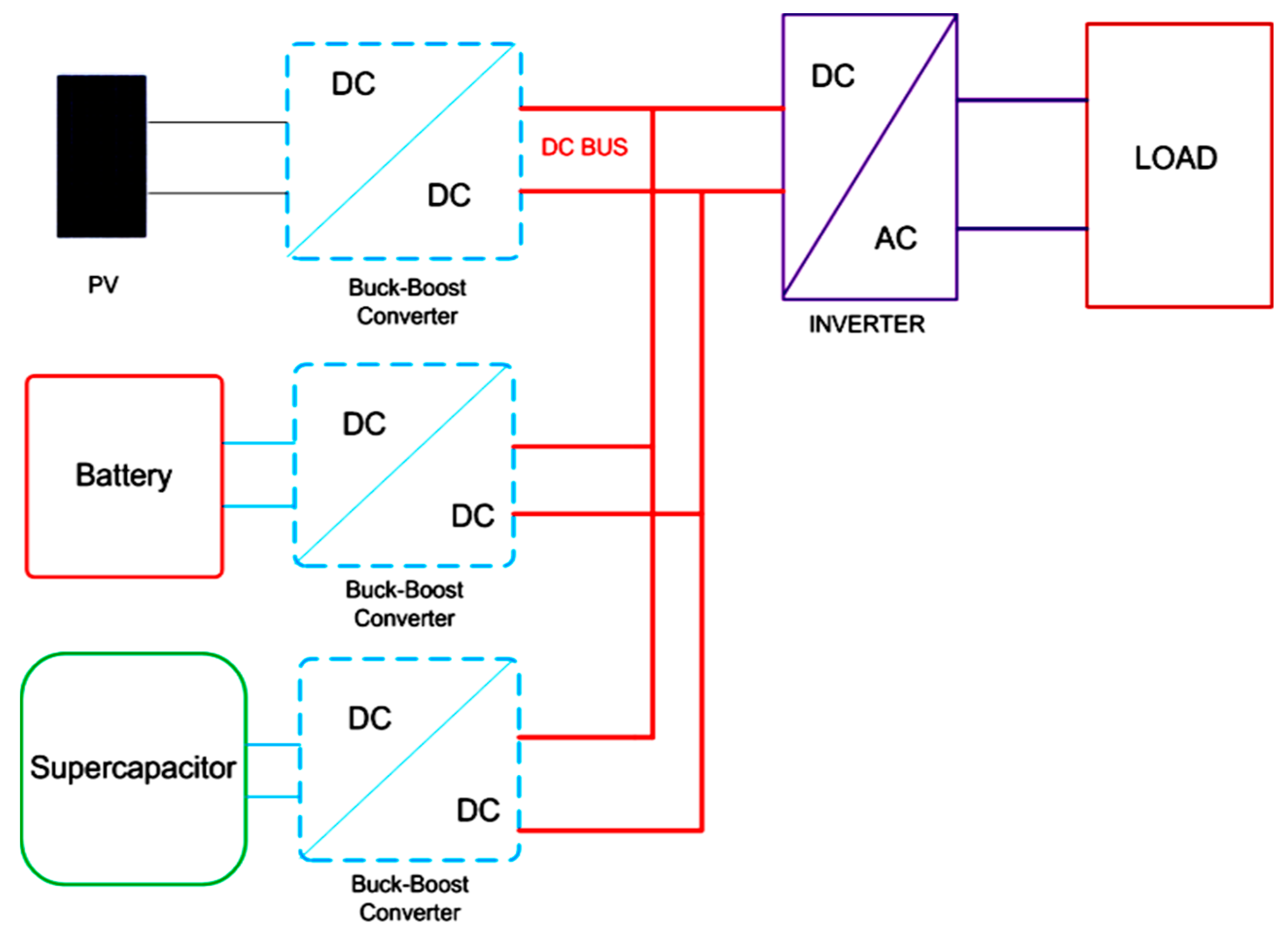
Figure 1 shows a separate converter type HESS based PV system. In this type of configuration, two bidirectional buck-boost converters are used to control the energy flow of battery and supercapacitor. A separate boost converter is also used with PV modules to implement maximum power point tracking (MPPT) in this configuration. The beauty of this type of configuration is that it can independently control the energy of both energy storage systems (battery and supercapacitor).
2.1.1. Modeling of HESS
A HESS comprises of more than one energy storage component. In this paper, the battery and supercapacitor are connected together as a HESS. The mathematical modeling of supercapacitor and HESS based PV system are described below.
2.1.2. Modeling of Supercapacitor
The model of supercapacitor is a simple series RC model, as illustrated in Figure 2 The supercapacitor is nothing but a simple capacitor having large electric charge storing capacity. This adapted supercapacitor model is simple and accurate in validating the HESS in small PV systems [19]. Equation (1) shows the voltage and current relationship of supercapacitor.
2.2. Modeling of Proposed HESS Based PV System
Figure 3 depicts the proposed HESS based PV system. This HESS based PV system is based on mixed converter type topology. In this topology, separate bidirectional buck/boost converters are used to control the power flow of battery and supercapacitor. A control algorithm controls both buck/boost converters that are associated with the battery and the supercapacitor to meet the power demand on the DC bus. The overall system equation is as given in (2).
where PPV, PBT, PSC, and PL denoted the power outputs of PV, battery, supercapacitor, and load power, respectively.
The efficiencies of supercapacitors and batteries are represented as in (3) and (4), where PASC and PABT are the ratings of supercapacitor and battery, respectively. Their efficiencies of supercapacitor and battery are denoted by ηSC and ηBT, respectively.
The required power, ΔP, on the DC bus is as expressed in (5)
The storage devices are required to provide ΔP, as in (6).
3. Control Strategies for HESS
Different strategies are used to control the power flow between DC bus and HESS. In the literature, the control strategies are classified as classical and intelligent control strategies [23]. Rule based controller (RBC) and filtration-based controller (FBC) are two further categories of classical strategies. RBC and FBC are simple and easy to implement, but the former is very sensitive while the latter is rigid [24,25,26]. Intelligent control strategies, such as fuzzy logic control (FLC), are reliable and efficient options.
3.1. Rule Based Controller (RBC)
RBC uses a set of rules to decide the power flow between the battery/DC Bus or Supercapacitor/DC Bus. Due to the simplicity of this technique, it does not require high processing, however it is very sensitive to system parameter variations. An RBC, in [27], is reworked and shown in Figure 4a. The IB1 and IB2 are the battery current thresholds and K1 and K2 are the slope gradients. When the battery current is within the limit of IB1 and IB2 the battery only supplies the power to load. When the battery current exceeds the threshold limit IB1 or IB2, the extra power demand will be provided by both the battery and the SC. The general design and performance analysis of RBC controller are explained in detail in [28].
3.2. Filtration Based Controller (FBC)
The FBC based controller uses a filter to extract the dynamic components of the power as high-frequency and low-frequency components. Due to simplicity, this technique requires less complication. Figure 4b illustrates the high-pass filter (HPF) based FBC, which is adopted from [29]. The high frequency component (PHF) and low frequency component (PLF) describe the power demand. The design and performance analysis are described in detail in [30].
4. Proposed Fuzzy based HESS Control Strategy (FHCS)
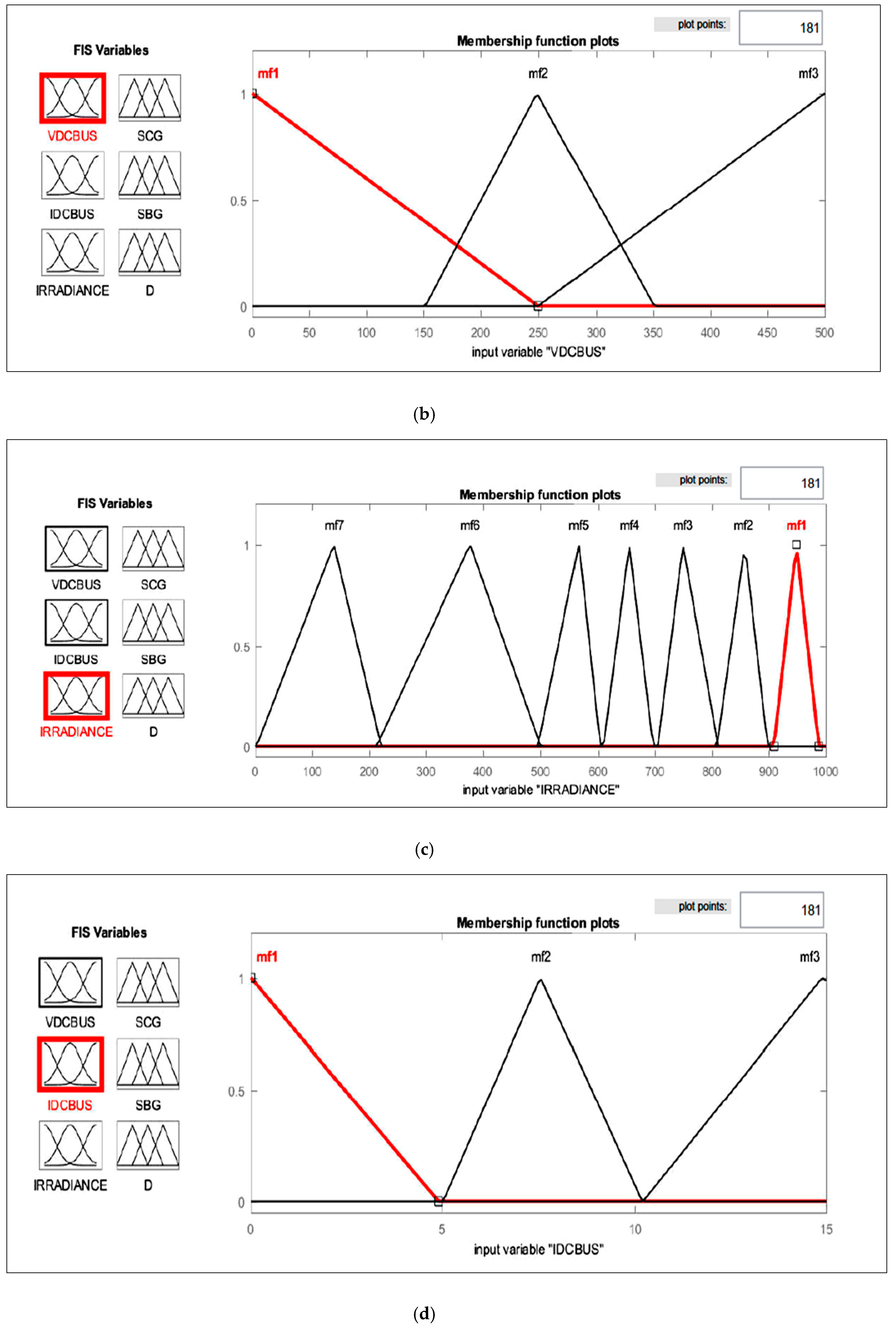
The proposed FHCS is described in Figure 5a. This control strategy controls the power flow between HESS and DC bus according to the proposed fuzzy rules. Solar irradiance Ir, DC bus voltage VDC and current IDC used as the input parameters to fuzzy controller. ΔP is deficient or required power and ΔIr is change in solar irradiance. The fuzzy controller controls the power between the supercapacitor to DC bus and battery to DC bus while using a switch connected between them. The FHCA generates SCG and SBG control signal to operate the switches, respectively, and also controls the buck/boost converter duty cycle associated with them. This control scheme also decides when power should be delivered to the DC bus or when the battery/supercapacitor should be charged. Thus, duty cycle, SCG, and SBG control signals are considered as the output parameters of fuzzy controller, as shown in Figure 5b. For developing a fuzzy control strategy, the first step is to define different membership functions and the values of input and output parameters in each function. For the proposed FHCS the values of different membership functions considered, in this paper, are listed Table 1 Based on the possible maximum and minimum ranges of different parameters, eight membership functions with combinations of different parameter value ranges are defined. The fuzzy rules that formed based on the membership functions are shown in Figure 6a–e.
4.1. Battery Control
FHCS generates a control signal (SBG) to open/close the switch connected between them to control the power flow between battery and DC bus. This control signal allows for the power flow from battery to DC bus and vice versa according to input conditions. The benefit of this control strategy is that it also controls the duty cycle of battery buck/boost converter according to the demand of DC bus. The power of battery is only used during linear transient conditions; during fast transient and constant radiation conditions, only the supercapacitor is used to compensate the deficient power on DC bus. This control mechanism stabilizes the power at DC bus based on load side demand and available input power. The membership function of SBG and its values are summarized in Figure 6a–c and Table 1.
4.2. Supercapacitor Control
The supercapacitor has the property of charging and discharging very fast. It can provide high power for a short interval of time. Therefore, it is beneficial to balance the power flow on DC bus under the fast transient or partial shading condition. The FHCS detects the fast-transient conditions and controls the supercapacitor power flow using SCG signal as well as buck/boost converter’s duty cycle D. The supercapacitor power is only used during fast transient conditions to stabilize the power on the DC bus. This control mechanism saves the battery from unnecessary charge/discharge operation and enhances the battery life, which is the key motive of this work. The membership function of SCG and its values are described in Figure 6a–c and Table 1.
4.3. HESS Duty Cycle Control
The duty cycle of book/boost converter is used to control power flow of battery/supercapacitor to the DC bus. The duty cycle varies between 5% and 80% according to power deficiency and load demand. The variation in buck/boost converter duty cycle makes DC bus voltage and current stable. The membership functions, mf1 to mf8, and Table 1 shows their values.
5. HESS Size Calculations and Stand-alone PV System Description
In this work, a standalone PV system is designed to evaluate the performance of HESS based stand-alone PV system. A 5-kW standalone PV system is considered with HESS for energy backup. HESS is formulated with battery and supercapacitor connected in separate converter type topology. The battery and supercapacitor sizes depend on PV system capacity, amount of backup needed, and radiation transients.
5.1. HESS Size Calculations
The size of HESS affects the performance of standalone PV system and its overall cost. The basic size of battery and supercapacitor is formulated, as follows.
5.1.1. Battery Size Calculation
The battery capacity is considered in amperes hours (Ah).
where, P is power, I is current in amperes, and is battery voltage in volts.
where ib is battery current and h is time in hours.
Replacing these values in Equation (7), we get
Now, rearranging the equation gives
where Ah is the required battery capacity and it is represented in terms of P, rated power of PV system.
5.1.2. Supercapacitor Size Calculation
Supercapacitor size is considered in Farad (F).
where q is charge, VSC is voltage, CSC is capacitance, ISC is current, and t is time.
From Equations (12) and (13), it can be derived
where Csc is supercapacitor size in Farad, Vsc is supercapacitor voltage, and P is PV system power.
5.2. Stand-alone PV System Description
In the studied model, a standalone PV system consists of a PV array, a charge controller, battery bank, and an inverter. In this work, a Canadian Solar CS6P-250PT 250 W PV module is used to simulate the PV system. Four PV modules in total are connected for a 5 kW standalone PV system having two strings and each string consists of two modules. Figure 7 shows the characteristics of Canadian solar PV module. A classical DC-DC boost converter is used to boost up the voltage of PV array and a DC-DC buck-boost converter is used to charge and discharge the battery/supercapacitor. Table 2 lists the components, their quantities, and ratings. Battery and supercapacitor ratings are calculated while using Equations (11) & (17).
6. Simulation Results and Analysis
The designed HESS based PV system with FHCS. as described above, is simulated while using MATLAB/Simulink simulation environment. This PV system is simulated for 60 s using input irradiance defined for real time data is shown in Figure 8a–c. The input radiation is split into three time slots. The fast transient phase is from 0 to 10 s, linear changing phase is of 10 to 50 s, and a radiation constant phase of 50 to 60 s. The generated PV system power, DC bus power, and output power are shown in Figure 8a–c, respectively. Figure 8b shows DC bus power, voltage, and current variation. Here, the DC bus power is the sum of generated PV power and HESS power.
6.1. Fast Transient Phase Analysis (0 to 10 s)
During the fast-transient phase, the irradiance is frequently changing. The input current changes according to irradiance and the input voltage oscillates between 200 to 300 volts as shown in Figure 8a. The DC bus current has a few oscillations and DC bus voltage has minimal spikes. The DC bus power is constant at 5kW with some oscillations between 0 to 10 s. The output or AC power, AC voltage, and AC current are almost constant, irrespective of radiation change, as shown in Figure 8c. Figure 8d,e show the battery and supercapacitor current and SOC graph. The battery current is zero and the SOC is 70.3% and supercapacitor current and SOC are changing according to irradiance change. The supercapacitor current and SOC are changing from −11 to 13 amp and 24% to 80%, respectively. This clearly indicates that, during the fast transient phase, this algorithm only uses the supercapacitor power to compensate the deficient power on DC bus and saves battery from an unnecessary charging/discharging process.
6.2. Linear Changing Phase Analysis (15 to 50 s)
From 15 to 50 s, the irradiance linearly changes, as shown in Figure 8a. During this phase the input power is changing according to irradiance, but DC bus power and output power are constant. The battery current and SOC changes from 0 to 4.5 amp and 70.35% to 70.15% respectively. The supercapacitor current and SOC do not change in this phase. This algorithm compensates the deficient power on DC bus using battery bank.
6.3. Constant Phase Analysis (10 to 15 and 50 to 60 s)
The phase in which there is no change in irradiance is called constant phase. From 10 to 15 s, the supercapacitor current and SOC changes −10 to 0 amp and approximately 30% to 80%, which indicates that supercapacitor is charging. In this phase, the battery current and SOC is constant. During 50 to 60 s the battery current is changing from 0 to −4 amp approx. and SOC changes 70.25% to 70.35%. In this phase, supercapacitor and battery current are not used, because there is sufficient PV power is available. There is no deficiency of power on the DC bus.
7. Battery Charging/Discharging Cycle and its Effects on Battery Life Span
7.1. Battery Charging/Discharging Cycle
Frequent or irregular battery charging/discharging process affects the battery performance, degrades the storage capacity and also leads to the loss of energy [31,32]. For a prolonged life span, the battery needs to be charged with a constant current for specific time duration. The generated solar power is radiation dependent and variable. It varies according to weather conditions and it damages the battery by inducing dynamic charging/discharging stress, and thus reduces the life span.
The amount of true cycle capacity loss is directly proportional to the square root of charge-discharge cycle numbers and can be expressed, as given below in Equation 18 [33].
where, kc is reaction constant.
The battery life span can be enhanced by reducing charge-discharge cycle numbers. The proposed system reduces the dynamic stress on battery using supercapacitor as secondary energy storage.
The supercapacitor prevents the battery from unnecessary charge-discharge operations and compensates the deficient power during fast transient or sudden radiation change condition. In this work, the performance of the proposed HESS based PV system is investigated while using 10 s input transient. The output power during this time span is constant and voltage is found to be stable. The SOC and current of supercapacitor change, but battery SOC and current are constant during this transient. This HESS based PV system and control algorithm prevents the battery due to worst effect of several numbers of these fast transients during the whole day.
7.2. Battery Life Span Analysis
Solar transients affect the battery operation and decrease its life span. One-year data of Sultanpur, India (latitude [N] 26.29 longitude [E] 82.08) is analyzed to investigate the number of fast and linear transient’s pattern of solar radiation. Figure 9 shows an example of identified fast or linear transients. The discrimination of fast and linear transient is decided while using Equation (19) below.
Table 3 provides the average numbers of fast and linear transients that were obtained for each month. The maximum number of fast and linear transients are encountered in the months of August (389) and February (168), respectively. The total number of charge-discharge cycles used without and with HESS based PV system are 3701 and 1079, respectively. From Table 4, it is evident that the total number of cycles saved is 2622 during whole year with maximum being in the month of July i.e. Hence, HESS based PV system saved 70.84% cycles as compared to no HESS based PV system case.
8. Conclusions
In this work, a HESS based stand-alone PV system and a FHCS is developed for domestic rural applications. The HESS is composed of battery and supercapacitor. The performance of the system is investigated under fast transient and linearly changing radiation conditions. Simulation studies of the proposed FHCS based stand-alone PV system are carried out while using real data collected in Sultanpur, India (Latitude [N] 26.29 and Longitude [E] 82.08). The output power and voltage are found stable under both conditions. The charging-discharging stress on battery is also reduced, which enhances the battery life span and reduces the maintenance cost of the system. In contrast with other control strategies for HESS based stand-alone PV system, FHCS is more reliable, yet a simple and effective solution. As future work, the efficacy of the proposed FHCS strategy can be further investigated by implementing it on a real stand-alone PV system or a test bed with relevant hardware.
Author Contributions
Conceptualization and methodology, K.J., H.A., R.S., S.M.S.H. and T.S.U.; software and validation, K.J.; writing—original draft preparation, K.J., H.A. and R.S.; writing—review and editing, S.M.S.H. and T.S.U.; supervision, H.A., S.M.S.H., T.S.U. and R.S.; funding acquisition, S.M.S.H.
Funding
This research received no external funding.
Acknowledgments
This work was supported in part by Visvesvaraya PhD scheme by Department of Electronics and Information Technology (DeitY) Government of India (implemented by Digital India Corporation formally Media Lab Asia) as financial support to Kashif Javed and by Fukushima prefecture’s reconstruction fund 2019.
Conflicts of Interest
The authors declare no conflict of interest.
References
- Almeshqab, F.; Ustun, T.S. Lessons learned from rural electrification initiatives in developing countries: Insights for technical, social, financial and public policy aspects. Renew. Sustain. Energy Rev. 2019, 102, 35–53. [Google Scholar] [CrossRef]
- Hubble, A.H.; Ustun, T.S. Composition, placement, and economics of rural microgrids for ensuring sustainable development. Sustain. Energy Grids Networks 2018, 13, 1–18. [Google Scholar] [CrossRef]
- Ustun, T.S.; Nakamura, Y.; Hashimoto, J.; Otani, K. Performance analysis of PV panels based on different technologies after two years of outdoor exposure in Fukushima, Japan. Renew. Energy 2019, 136, 159–178. [Google Scholar] [CrossRef]
- Bruno, S.; Dellino, G.; La Scala, M.; Meloni, C. A Microforecasting Module for Energy Management in Residential and Tertiary Buildings. Energies 2019, 12, 1006. [Google Scholar] [CrossRef]
- Dellino, G.; Laudadio, T.; Mari, R.; Mastronardi, N.; Meloni, C.; Vergura, S. Energy production forecasting in a PV plant using transfer function models. In Proceedings of the 2015 IEEE 15th International Conference on Environment and Electrical Engineering (EEEIC), Rome, Italy, 10–13 June 2015; pp. 1379–1383. [Google Scholar]
- Ju, C.; Wang, P.; Goel, L.; Xu, Y. A Two-Layer Energy Management System for Microgrids With Hybrid Energy Storage Considering Degradation Costs. IEEE Trans. Smart Grid 2018, 9, 6047–6057. [Google Scholar] [CrossRef]
- Kan, S.Y.; Verwaal, M.; Broekhuizen, H. The use of battery–capacitor combinations in photovoltaic powered products. J. Power Sources 2006, 162, 971–974. [Google Scholar] [CrossRef]
- Nadeem, F.; Hussain, S.M.S.; Tiwari, P.K.; Goswami, A.K.; Ustun, T.S. Comparative Review of Energy Storage Systems, Their Roles, and Impacts on Future Power Systems. IEEE Access 2019, 7, 4555–4585. [Google Scholar] [CrossRef]
- Baisden, A.; Emadi, A. ADVISOR-Based Model of a Battery and an Ultra-Capacitor Energy Source for Hybrid Electric Vehicles. IEEE Trans. Veh. Technol. 2004, 53, 199–205. [Google Scholar] [CrossRef]
- Dougal, R.A.; Liu, S.; White, R.E. Power and life extension of battery ultracapacitor hybrids. IEEE Trans. Compon. Package Technol. 2002, 25, 120–131. [Google Scholar] [CrossRef]
- Jing, W.; Lai, C.H.; Wong, S.H.W.; Wong, M.L.D.; Wong, W.; Wong, M.L.D. Battery-supercapacitor hybrid energy storage system in standalone DC microgrids: A review. IET Renew. Power Gener. 2017, 11, 461–469. [Google Scholar] [CrossRef]
- Thounthong, P.; Rael, S.; Davat, B. Analysis of Supercapacitor as Second Source Based on Fuel Cell Power Generation. IEEE Trans. Energy Convers. 2009, 24, 247–255. [Google Scholar] [CrossRef]
- Wang, G.; Ciobotaru, M.; Agelidis, V.G. Power Smoothing of Large Solar PV Plant Using Hybrid Energy Storage. IEEE Trans. Sustain. Energy 2014, 5, 834–842. [Google Scholar] [CrossRef]
- Chia, Y.Y.; Lee, L.H.; Shafiabady, N.; Isa, D. A load predictive energy management system for supercapacitor-battery hybrid energy storage system in solar application using the Support Vector Machine. Appl. Energy 2015, 137, 588–602. [Google Scholar] [CrossRef]
- Pan, T.L.; Wan, H.-S.; Ji, Z.-C. Stand-alone wind power system with battery/ supercapacitor hybrid energy storage. Int. J. Sustain. Eng. 2014, 7, 103–110. [Google Scholar] [CrossRef]
- Song, Y.D.; Cao, Q.; Du, X.; Karimi, H.R. Control Strategy Based on Wavelet Transform and Neural Network for Hybrid Power System. J. Appl. Math. 2013, 2013, 1–8. [Google Scholar] [CrossRef]
- Gee, A.M.; Robinson, F.V.P.; Dunn, R.W. Analysis of Battery Lifetime Extension in a Small-Scale Wind-Energy System Using Supercapacitors. IEEE Trans. Energy Convers. 2013, 28, 24–33. [Google Scholar] [CrossRef]
- Chong, L.W.; Wong, Y.W.; Rajkumar, R.K.; Isa, D. An optimal control strategy for standalone PV system with Battery-Supercapacitor Hybrid Energy Storage System. J. Power Sources 2016, 331, 553–565. [Google Scholar] [CrossRef]
- Wieczorek, M.; Lewandowski, M. A mathematical representation of an energy management strategy for hybrid energy storage system in electric vehicle and real time optimization using a genetic algorithm. Appl. Energy 2017, 192, 222–233. [Google Scholar] [CrossRef]
- Wang, X.; Yu, D.; Le Blond, S.; Zhao, Z.; Wilson, P. A novel controller of a battery-supercapacitor hybrid energy storage system for domestic applications. Energy Build. 2017, 141, 167–174. [Google Scholar] [CrossRef] [Green Version]
- Thounthong, P. Model Based-Energy Control of a Solar Power Plant with a Supercapacitor for Grid-Independent Applications. IEEE Trans. Energy Convers. 2011, 26, 1210–1218. [Google Scholar] [CrossRef]
- Brunelli, D.; Moser, C.; Thiele, L.; Benini, L. Design of a Solar-Harvesting Circuit for Batteryless Embedded Systems. IEEE Trans. Circuits Syst. I Regul. Pap. 2009, 56, 2519–2528. [Google Scholar] [CrossRef]
- Chong, L.W.; Wong, Y.W.; Rajkumar, R.K.; Rajkumar, R.K.; Isa, D. Hybrid energy storage systems and control strategies for stand-alone renewable energy power systems. Renew. Sustain. Energy Rev. 2016, 66, 174–189. [Google Scholar] [CrossRef]
- Brka, A.; Kothapalli, G.; Al-Abdeli, Y.M. Predictive power management strategies for stand-alone hydrogen systems: Lab-scale validation. Int. J. Hydrog. Energy 2015, 40, 9907–9916. [Google Scholar] [CrossRef]
- Garcia-Torres, F.; Bordons, C. Optimal Economical Schedule of Hydrogen-Based Microgrids With Hybrid Storage Using Model Predictive Control. IEEE Trans. Ind. Electron. 2015, 62, 5195–5207. [Google Scholar] [CrossRef]
- Kuperman, A.; Aharon, I. Battery-ultracapacitor hybrids for pulsed current loads: A review. Renew. Sustain. Energy Rev. 2011, 15, 981–992. [Google Scholar] [CrossRef]
- Ali Akcayol, M. Application of adaptive neuro-fuzzy controller for SRM. Adv. Eng. Softw. 2004, 35, 129–137. [Google Scholar] [CrossRef]
- Zhang, Y.; Jiang, Z.; Yu, X. Control strategies for Battery/Supercapacitor Hybrid Energy Storage Systems. In Proceedings of the 2008 IEEE Energy 2030 Conference, Atlanta, GA, USA, 17–18 November 2008; pp. 5–10. [Google Scholar]
- Kollimalla, S.K.; Mishra, M.K.; Narasamma, N.L. Design and Analysis of Novel Control Strategy for Battery and Supercapacitor Storage System. IEEE Trans. Sustain. Energy 2014, 5, 1137–1144. [Google Scholar] [CrossRef]
- Mendis, N.; Muttaqi, K.M.; Perera, S. Active power management of a super capacitor-battery hybrid energy storage system for standalone operation of DFIG based wind turbines. In Proceedings of the 2012 IEEE Industry Applications Society Annual Meeting, Las Vegas, NV, USA, 7–11 October 2012; pp. 1–8. [Google Scholar]
- Lei, Y.; Zang, C.; Gao, Y.; Li, T. Charging optimization of Lithium-ion Batteries Based on Capacity Degradation Speed and Energy Loss. Energy Procedia 2018, 152, 544–549. [Google Scholar] [CrossRef]
- Serhan, H.A.; Ahmed, E.M. Effect of the different charging techniques on battery life-time: Review. In Proceedings of the 2018 International Conference on Innovative Trends in Computer Engineering (ITCE), Aswan, Egypt, 19–21 February 2018. [Google Scholar]
- Yoshida, H.; Imamura, N.; Inoue, T.; Takeda, K.; Naito, H. Verification of Life Estimation Model for Space Lithium-Ion Cells. Electrochemistry 2010, 78, 482–488. [Google Scholar] [CrossRef] [Green Version]
Figure 1.
Hybrid energy storage system (HESS) Based Photovoltaic (PV) System.

Figure 2.
Supercapacitor Model.

Figure 3.
Proposed HESS Based Stand-alone PV System for Domestic Application.

Figure 4.
(a) Rule Based Controller (RBC), (b) Filtration Based Controller (FBC).

Figure 5.
(a) Proposed Fuzzy based HESS Control (b) Input and Output of Fuzzy Logic System.

Figure 6.
(a) Fuzzy Rules Diagram; (b) DC Bus Voltage Membership Functions; (c) DC Bus Current Membership Functions; (d) Irradiance Membership Functions; and, (e) Duty Cycle Membership Functions.
Figure 6.
(a) Fuzzy Rules Diagram; (b) DC Bus Voltage Membership Functions; (c) DC Bus Current Membership Functions; (d) Irradiance Membership Functions; and, (e) Duty Cycle Membership Functions.


Figure 7.
Canadian Solar Module Characteristics.

Figure 8.
(a) Generated PV Power, Voltage, Current and Input Irradiance; (b) DC bus Power, Current and Voltage; (c) Output AC Power, Current and Voltage; (d) Battery Current and state of charge (SOC); and, (e) Supercapacitor Current and SOC.
Figure 8.
(a) Generated PV Power, Voltage, Current and Input Irradiance; (b) DC bus Power, Current and Voltage; (c) Output AC Power, Current and Voltage; (d) Battery Current and state of charge (SOC); and, (e) Supercapacitor Current and SOC.


Figure 9.
Typical Example of One Day Solar Radiation for Identification of Fast Transients Occurs on Latitude [N] 26.29 and Longitude [E] 82.08 (Sultanpur, India) Location.
Figure 9.
Typical Example of One Day Solar Radiation for Identification of Fast Transients Occurs on Latitude [N] 26.29 and Longitude [E] 82.08 (Sultanpur, India) Location.


Table 1.
Values of Membership Functions.
| mf | VDC BUS (volt) | IDC BUS (amp) | Irradiance (W/m2) | SCG | SBG | DUTY CYCLE (%) |
|---|---|---|---|---|---|---|
| mf1 | 0–250 | 0–5 | 900–1000 | 0 | 0 | 5–10 |
| mf2 | 150–350 | 5–10 | 800–900 | 1 | 1 | 10–20 |
| mf3 | 250–500 | 10–15 | 700–800 | 20–30 | ||
| mf4 | 600–700 | 30–40 | ||||
| mf5 | 500–600 | 40–50 | ||||
| mf6 | 200–500 | 50–60 | ||||
| mf7 | 0–200 | 60–70 | ||||
| mf8 | 70–80 |
Table 2.
List of Components.
| S.No. | Component | Rating | Quantity |
|---|---|---|---|
| 1 | PV Module | 250 W | 20 |
| 2 | Battery | 65 Ah | 1 |
| 3 | Supercapacitor | 100 F | 1 |
| 4 | Load | 5 kW | 1 |
Table 3.
Transient Analysis of Sultanpur, India for 2016 (Latitude [N] 26.29 and Longitude [E] 82.08).
Table 3.
Transient Analysis of Sultanpur, India for 2016 (Latitude [N] 26.29 and Longitude [E] 82.08).
| No of Average Transients/ Month | ||||||||
|---|---|---|---|---|---|---|---|---|
| Month | No of Average Transients | Battery Charging/Discharging Cycles without HESS | Battery Charging/Discharging Cycles with HESS | |||||
| Fast Transients | Linear Transients | During Fast Transients | During Linear Transients | Total Cycle | During Fast Transients | During Linear Transients | Total Cycle | |
| January | 247 | 101 | 247 | 101 | 348 | 0 | 101 | 101 |
| February | 252 | 168 | 252 | 168 | 420 | 0 | 168 | 168 |
| March | 124 | 87 | 124 | 87 | 211 | 0 | 87 | 87 |
| April | 107 | 61 | 107 | 61 | 168 | 0 | 61 | 61 |
| May | 92 | 51 | 92 | 51 | 143 | 0 | 51 | 51 |
| June | 88 | 43 | 88 | 43 | 131 | 0 | 43 | 43 |
| July | 521 | 57 | 521 | 57 | 578 | 0 | 57 | 57 |
| August | 389 | 116 | 389 | 116 | 505 | 0 | 116 | 116 |
| September | 357 | 102 | 357 | 102 | 459 | 0 | 102 | 102 |
| October | 133 | 117 | 133 | 117 | 250 | 0 | 117 | 117 |
| November | 66 | 59 | 66 | 59 | 125 | 0 | 59 | 59 |
| December | 246 | 117 | 246 | 117 | 363 | 0 | 117 | 117 |
| Total Number of Cycles | 3701 | 1079 | ||||||
Table 4.
Average Cycles Saved Analysis.
| Month | Number of Cycles Saved | Cycles Saved (%) |
|---|---|---|
| January | 247 | 70.9% |
| February | 252 | 60.0% |
| March | 124 | 58.7% |
| April | 107 | 63.6% |
| May | 92 | 64.3% |
| June | 88 | 67.1% |
| July | 521 | 90.1% |
| August | 389 | 77.0% |
| September | 357 | 77.7% |
| October | 133 | 53.2% |
| November | 66 | 52.8% |
| December | 246 | 67.7% |
| Total | 2622 | 70.84% |
© 2019 by the authors. Licensee MDPI, Basel, Switzerland. This article is an open access article distributed under the terms and conditions of the Creative Commons Attribution (CC BY) license (http://creativecommons.org/licenses/by/4.0/).
Share and Cite
MDPI and ACS Style
Javed, K.; Ashfaq, H.; Singh, R.; Hussain, S.M.S.; Ustun, T.S. Design and Performance Analysis of a Stand-alone PV System with Hybrid Energy Storage for Rural India. Electronics 2019, 8, 952. https://doi.org/10.3390/electronics8090952
AMA Style
Javed K, Ashfaq H, Singh R, Hussain SMS, Ustun TS. Design and Performance Analysis of a Stand-alone PV System with Hybrid Energy Storage for Rural India. Electronics. 2019; 8(9):952. https://doi.org/10.3390/electronics8090952
Chicago/Turabian StyleJaved, Kashif, Haroon Ashfaq, Rajveer Singh, S.M. Suhail Hussain, and Taha Selim Ustun. 2019. "Design and Performance Analysis of a Stand-alone PV System with Hybrid Energy Storage for Rural India" Electronics 8, no. 9: 952. https://doi.org/10.3390/electronics8090952
Note that from the first issue of 2016, this journal uses article numbers instead of page numbers. See further details here.