Article

The Control Parameter Determination Method for Bidirectional DC-DC Power Converters Interfaced Storage Systems Based on Large Signal Stability Analysis

1
School of Electrical and Control Engineering, North China University of Technology, Beijing 100000, China
2
School of Civil Engeneering, North China University of Technology, Beijing 100000, China
*
Author to whom correspondence should be addressed.
Electronics 2019, 8(9), 1018; https://doi.org/10.3390/electronics8091018
Submission received: 26 August 2019 / Revised: 6 September 2019 / Accepted: 9 September 2019 / Published: 11 September 2019
(This article belongs to the Section Systems & Control Engineering)

Abstract

:
In DC microgrid (DC-MG), the loads connected with converters under strict control are considered as CPLs (constant power loads). When the voltage of CPLs decreases, the current increases and the negative impedance characteristic of CPLs cause instability easily. Fortunately, appropriate control for energy storage units could improve the system stability. However, most traditional control methods for bidirectional DC-DC power converters (BDC) connected with battery storage units do not quantitatively consider the stability influences of control parameters. This paper quantitatively analyzes the stability influence of the BDC current-mode control parameters and the negative impact of CPLs and derives the control parameter determination method for BDC interfaced storage systems. Large signal stability constraints are obtained in terms of mixed potential function. According to the constraints, the large signal stability is improved when the BDC control parameter kp increases, while the stability is degraded when the power of CPLs increases. The control parameter determination method is very effective and convenient to apply, and the appropriate parameter kp for BDC is determined. The regions of asymptotic stability (RAS) identify that the proposed control parameter determination method could improve the system stability effectively. The determination method is fully verified by the simulation and experimental results.

1. Introduction

With the development of DC power source and energy storage technology, more and more articles pay attention to the DC microgrid (DC-MG). DC-MG has broad application prospects, just as the maritime DC-MG in the research of Zheming Jin, Mehdi Savaghebi and Juan C. Vasquez et al. [1], the more electric aircraft in the research of Giampaolo Buticchi, Levy Costa and Marco Liserre [2]. DC-MG consists of micro-sources, energy storage units, loads and power converters. A lot of research shows that the loads connected with converters could be considered as constant power loads (CPLs) under strict control [3,4,5]. The CPLs exhibit negative impedance characteristics when disturbance occurs, which would easily cause system instability. Moreover, there are multiple load converters and energy storage converters in DC-MG, the interacting of these converters could aggravate instability problems [6]. Consequently, the stability analysis is particularly important in DC-MG and that is a complex problem.
The methods of solving the instability problem caused by CPLs are divided into passive methods and active methods. The passive methods focus on adding components [7,8], while active methods focus on the system control strategies [9,10,11,12]. In recent years, a large number of researchers have paid more attention to improving the system stability through active methods. A lot of research indicates that the appropriate control for the energy storage unit is important in improving the stability of DC-MG. In the research of Raymond H. Byrne, Tu A. Nguyen and David A. Copp et al. [13], the management methods for the energy storage system in the grid is reviewed, the efficiency, stability of the power grid can be improved thanks to the energy storage system. The research of AKM Kamrul Hasan, Mohammed H. Haque and Syed Mahfuzul Aziz [14] indicates that the energy storage system can improve the damping of power system. The battery as storage element is widely used in the DC-MG with unique advantages. Battery packs are usually linked to the DC bus via bidirectional DC-DC power converters (BDC), and the related control methods attract more and more attention. The control scheme is mainly for controlling the transferring power of the battery storage unit, meanwhile maintaining stability [15]. Different kinds of schemes are proposed to control the BDC, such as current-mode control [16], sliding mode control [17] and model predictive control (MPC) [18,19]. However, the positive influence on stability of the control parameters is seldom considered in previous researches. In order to research the influence of control parameters on system stability, the system modeling and stability analysis are necessary. The stability analysis is divided into large signal stability and small signal stability analysis. In the research of Vishnu Mahadeva Iyer, Srinivas Gulur and Subhashish Bhattacharya [20], the small signal stability of bidirectional battery charger is assessed. The research of Seyed Ahmad Hamidi and Adel Nasiri [21] analyses the small signal stability of DC-DC converter for battery feeding CPL. Large signal stability ensures system stability under small disturbances, but the small signal stability does not necessarily guarantee the stability of the system under large disturbances [22]. Unfortunately, the large disturbances in generation and loads often occur in DC-MG [23]; the large signal stability analysis is essential. The research of Santiago Sanchez and Marta Molinas [24] and the research of Jakkrit Pakdeeto, Kongpan Areerak and Kongpol Areerak [25] analyze the large signal stability of DC-MG considering the large disturbances occur in system. The research of Hye-Jin Kim, Sang-Woo Kang and Gab-Su Seo et al. [26] analyses the large signal stability of DC power system based on the Takagi-Sugeno fuzzy model. In the research of Zekun Li, pWei Pei and Hua Ye et al. [27], the large signal of DC-MG under droop control is analyzed according to the mixed potential function. In our previous research [28], an active stabilization control strategy for BDC is proposed considering the large signal stability, but the system filter parameters are not taken into account, while only considering the characteristics of the CPLs. In this paper, the control parameters of the BDC, the filter parameters of system and CPLs are all considered simultaneously.
This paper proposes a current-mode control parameter determination method for BDC interfaced storage systems based on large signal stability analysis, and the CPLs are also considered. The large signal model of DC-MG is obtained based on the mixed potential function. According to the large signal model, the large signal stability constraints are derived. The appropriate parameter kp of current-mode control for BDC is determined according to the large signal stability constraints. Furthermore, the regions of asymptotic stability (RAS) of the system are obtained, which indicate that the control parameter determination method could improve the system stability effectively. Moreover, the determination method is fully verified by the simulation and experimental results.
This paper is organized as follows. In Section 2, the typical DC-MG topology is introduced. Then the large signal models of the system in the case of battery charging and discharging are obtained respectively. In Section 3, the large signal stability of the DC-MG is investigated, and the appropriate parameter kp of current-mode control for BDC is determined according to the large signal stability constraints. In Section 4, according to the proposed control parameter determined method, a DC-MG is designed and RAS of the system is obtained. In Section 5, the control parameter determination method is verified by simulation and experiments. This paper concludes in Section 6.

2. The DC-MG Topology and the Large Signal Model Construction

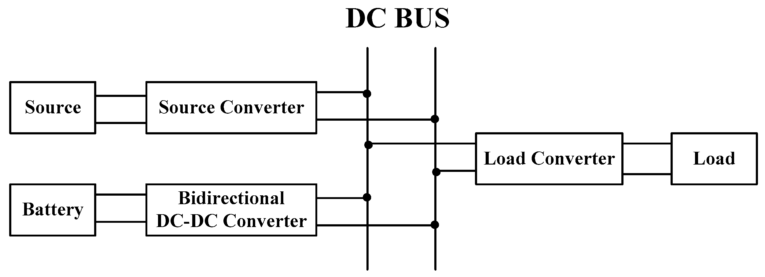
2.1. The DC-MG Topology

The power source is linked to the DC bus via the source converter. The loads are linked to the DC bus via strictly controlled converters and behave as CPLs. The battery pack is linked to the DC bus via the BDC. The generic DC-MG is shown as Figure 1.
BDCs play a key role in the DC-MG and could improve the stability of the system. The control method for BDC is mainly to control the transferring power of the battery storage unit, while maintaining the voltage of the DC bus. The current-mode control is popular for the BDC interfaced battery storage systems. The control method consists of two feedback loops, an outer DC bus voltage loop and an inner battery current loop, which is just shown in Figure 2. That control method is very effective and convenient to apply. Obviously, the parameter of the outer DC bus voltage loop is important to the system stability.

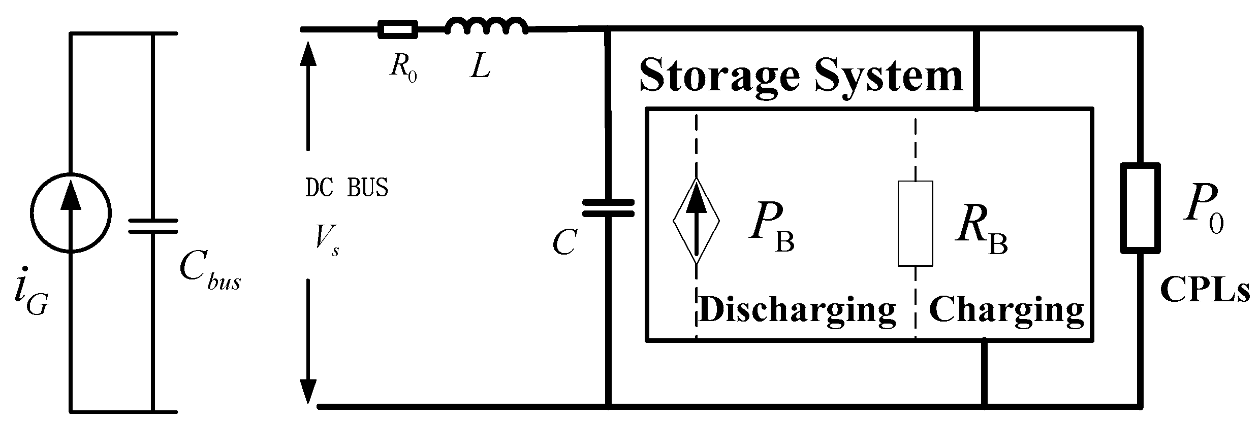
2.2. Large Signal Modeling

In this paper, the large signal model of DC-MG is obtained according to the mixed potential function proposed in the research of R.K. BRAYTON and J.K. MOSER [29]. The standard form of the mixed potential function is shown as follows:
P ( i , v ) = A ( i ) + B ( v ) + ( i , γ v α )
The accuracy of the function can be verified by Equation (2).
{ L d i ρ d t = P ( i , v ) i ρ C d v σ d t = P ( i , v ) v σ
Considering the different characteristics of each subsystem, the source converter is reasonably simplified to a current source iG, the closed-loop controlled load converter is equivalent to CPL P0, the BDC is equivalent to an impedance RB in the case of battery charging, which is regarded as a current source PB in the case of battery discharging. Under the regulation of the BDC, the voltage of bus capacitor is maintained at the reference value, and the DC bus exhibits the characteristics of a voltage source. The simplified system is shown in Figure 3.
The battery storage unit has different characteristics in different working conditions. Consequently, the large signal models of DC-MG in the case of battery charging and discharging need to be established respectively. Then, the mixed potential function is obtained according to the simplified DC-MG topology shown in Figure 3.
The large signal model P(i,v) of the system in the case of battery charging is obtained according to the mixed potential function.
P ( i , v ) = 1 2 R 0 i 2 + v 2 2 R B + 0 v P 0 v d v + i ( V s v )
It can be seen from Equation (4) that the obtained function is correct.
{ L d i d t = V s v R 0 i = P i C d v d t = i P 0 v v R B = P v
The large signal model P(i,v) of DC-MG in the case of battery discharging is obtained according to the mixed potential function.
P ( i , v ) = 1 2 R 0 i 2 0 v P B v d v + 0 v P 0 v d v + i ( V s v )
It can be seen from Equation (6) that the obtained mixed potential function is correct.
{ L d i d t = V s v R 0 i = P i C d v d t = i + P B v P 0 v = P v

3. Large Signal Stability Analysis

Brayton and Moser proposed the large signal stability theorems [29] when proposing the mixed potential function. The suitable theorem for DC-MG is as follows:
μ 1 + μ 2 δ ,   δ > 0
A i i ( i ) = 2 A ( i ) / i 2
B v v ( v ) = 2 B ( v ) / v 2
where μ1 is the minimum eigenvalue of L 1 / 2 A i i ( i ) L 1 / 2 , and μ2 is the minimum eigenvalue of C 1 / 2 B v v ( v ) C 1 / 2 .
And when | i | + | v | , the parameters also satisfy:
P * ( i , v ) = μ 1 μ 2 2 P ( i , v ) + 1 2 ( P i , L 1 P i ) + 1 2 ( P v , C 1 P v )
When the system satisfies Equations (7) and (10) at the same time, the system can finally be stable under large disturbances.
A. Large signal stability constraint of the system in the case of battery charging
According to the established mixed potential function in the case of battery charging, the large signal stability constraint is derived.
μ 1 = R 0 L
μ 2 = 1 C ( 1 R B P 0 v 2 )
1 R B > P 0 v 2 C R 0 L
According to the proposed stability constraint Equation (13), the appropriate control parameters for BDC can be obtained. From the outer DC bus voltage loop, the following is derived:
i b r e f = k p ( V d c V r e f ) + k I 0 t ( V d c V r e f ) d t
where i b r e f is the reference value of battery charging current, V d c is the sampled value of DC bus voltage, V r e f is the reference value of DC bus voltage.
Ignoring the power loss of the BDC, the input power and output power of the BDC are equal.
i B v = i b v b
where i B is the input current of BDC, i b is the battery charging current, v b is the battery voltage.
Then
i b = K i B
where K = v / V b .
According to Equation (13), the next is obtained.
d i b d v = k p + k I t > K ( P 0 v 2 C R 0 L )
Then
k p > K ( P 0 v 2 C R 0 L )
Based on Equation (18), the appropriate control parameters for BDC in the case of battery charging can be obtained.
B. Large signal stability constraint of the system in the case of battery discharging.
Based on the established mixed potential function in the case of battery discharging, the large signal stability constraint is derived.
μ 1 = R 0 L
μ 2 = 1 C ( d i B v P 0 v 2 )
d i B v > P 0 v 2 C R 0 L
According to the above Equation (21), the appropriate control parameters for BDC can be obtained. From the outer DC bus voltage loop, the following is derived:
i b r e f = k p ( V r e f V d c ) + k I 0 t ( V r e f V d c ) d t
where i b r e f is the reference value of battery discharging current, V d c is the sampled value of DC bus voltage, V r e f is the reference value of DC bus voltage.
Similarly, ignoring the power loss of the BDC, the input power and output power of the BDC are equal.
d i b d v = k p + k I t > K ( P 0 v 2 C R 0 L )
Then
k p > K ( P 0 v 2 C R 0 L )
Based on Equation (24), the appropriate control parameters for BDC in the case of battery discharging can be obtained.

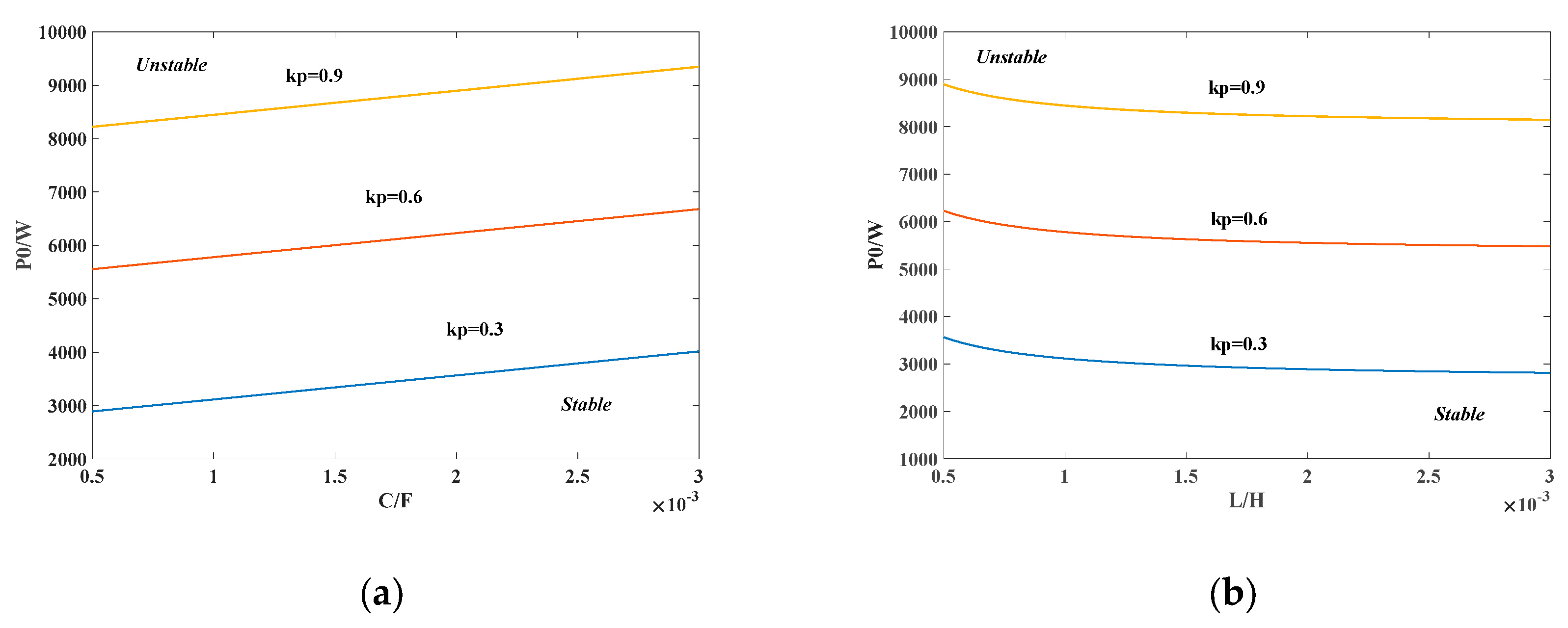
4. System Design and Region of Asymptotic Stability (RAS)

In order to verify the validity of the proposed control parameter determination method, a DC-MG as shown in Figure 3 is designed. The voltage of the DC bus is 380 V, the source power is 3 kW, the CPL increases from 0.5 kW to 5 kW. If the power of sources is greater than the power of loads, the power flow of the BDC is from the bus to the battery, if not, the power flows from the battery to the bus.
According to the proposed stability constraint for the control parameter for BDC determination, the large signal stability boundaries of various control parameter kp, filter capacitor C and filter inductor L can be obtained as shown in Figure 4. It is obvious that in Figure 4 the large signal stability is improved when the BDC control parameter kp increases.
Control parameters for BDC are determined considering the proposed large signal stability constraint, the filter inductor L is 1 mH, the filter capacitor C is 1000 μF, kp of the outer DC bus voltage loop in the case of battery charging is 0.3, kp of the outer DC bus voltage loop in the case of battery discharging is 0.6.
Then, according to the parameters of the system, the steady state equilibrium points of DC-MG in the case of battery charging and discharging are obtained. The following is derived:
{ i = P G V S = 7.89 A v = V S R 0 i = 379.8 V
At the same time, the RAS of the system can be obtained based on the LaSalle theorem [30].
R A S = { ( i , v ) : P * ( i , v ) min P * ( i , v min ) }
The RAS of the system in the case of battery charging and discharging shown in Figure 5 identifies that the proposed control parameter determination method could improve the system stability effectively. The RAS in the case of battery charging contains the stable equilibrium point (7.89 A, 379.8 V), and is large enough (the voltage varies from 150 V to 610 V, current varies from 0 A to 270 A). The RAS in the case of battery discharging contains the stable equilibrium point (7.89 A, 379.8 V), and is large enough (the voltage varies from 150V to 610V, current varies from 0A to 240 A).

5. The Control Parameter Determination Results and Verification

5.1. Simulation Experimental Topology and Design

In order to verify the validity of the control parameter determination method for BDC, the DC-MG is constructed according to Figure 6. The current source is the power source in the DC-MG, Cbus is the bus capacitance, R0 is the bus equivalent resistance, L is the filter inductor, C is the filter capacitor. The load is connected to the bus through a DC converter and the battery pack is connected to the bus through the BDC. The control method for load converter is voltage closed loop, the load connected with converter under strict control are considered as CPL. The control method for BDC consists of two feedback loops, an outer DC bus voltage loop and an inner battery current loop through the traditional PI control, which is just shown in Figure 2. The large disturbances in the experiment are both the load power step. Then the simulation model is built in MATLAB and the experiment rig is setup.
The experimental rig consists of photovoltaic simulator, battery energy storage unit and loads just as shown in Figure 7. In the experiment, the DC power source is the Chroma photovoltaic simulator, which can work as a voltage source or a current source. In the experiment, the photovoltaic simulator is applied as a current source. The power semiconductor devices in the BDC and load converter are both the BSM100GB120DN2K IGBT. The controller is DSP TMS320F28335.

5.2. Simulation Verification

A simple DC-MG according to Figure 6 is constructed in MATLAB to verify the control parameter determination for BDC could improve the system stability effectively. In the simulation, the DC bus voltage is 380 V, the filter inductor L is 1mH, the filter capacitor C is 1000 μF. The power of CPL steps from 500 W to 5 kW. Two groups of control parameters for BDC shown in Table 1 are adopted to verify the effectiveness of the parameter determination method. The kp of the outer DC bus voltage loop in the case of battery charging is obtained according to Equation (27):
k p > K ( P 0 v 2 C R 0 L ) = 0.0056
The kp of the outer DC bus voltage loop in the case of battery discharging is obtained according to Equation (28):
k p > K ( P 0 v 2 C R 0 L ) = 0.512
The simulation results are shown in Figure 8. In Figure 8a,b, the large disturbances are the same, both in the cases of power variations from 500 W to 5000 W. Comparing Figure 8a with Figure 8b, when the control parameters of the system meet the obtained constraints, the voltage of the DC bus could return to the reference 380 V as shown in Figure 8b. While the control parameters do not meet the constraints, the voltage of DC bus drops to 195 V and cannot return to the steady-state operating point as shown in Figure 8a. Based on the comparisons of Figure 8a,b, the proposed control parameter determination method for BDC based on large signal stability can improve the stability of the DC-MG as shown in the simulation results.

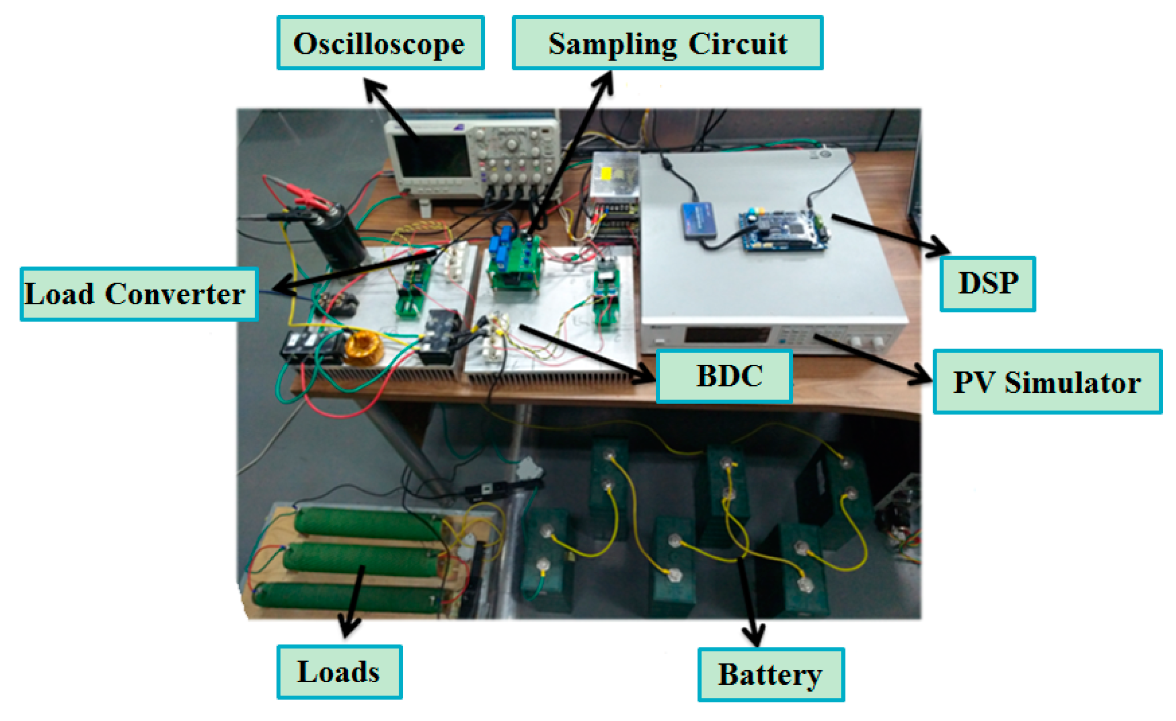
5.3. Experimental Verification

In this section, experimental verification is reported in order to verify that the control parameter determination for BDC could improve the system stability effectively. In the experimental rig, the DC bus voltage is 50 V, the power of CPL steps from 20 W to 100 W, the filter inductor L is 1 mH, and the filter capacitor C is 4700 μF. Two groups of control parameters for BDC shown in Table 2 are adopted to verify the effectiveness of the parameter determination method. The control parameters for BDC in the case of battery charging can be obtained based on Equation (18).
k p > K ( P 0 v 2 C R 0 L ) = 0 . 123
The control parameters for BDC in the case of battery discharging can be obtained based on Equation (24).
k p > K ( P 0 v 2 C R 0 L ) = 0.166
The experiment results are shown in Figure 9. In Figure 9a,b, the large disturbances are the same, in both cases of power variations from 20 W to 100 W. Comparing Figure 9a with Figure 9b, when the control parameters of the system meet the obtained constraints, the voltage of the DC bus could return to the reference 50 V as shown in Figure 9b. While the control parameters do not meet the constraints, the voltage of DC bus drops to 45 V and cannot return to the steady-state operating point as shown in Figure 9a. Based on the comparisons of Figure 9a,b, the proposed control parameter determination method for BDC based on large signal stability can improve the stability of the DC-MG as shown in the experimental results.
In order to further verify the control parameter determination for BDC which could improve the system stability effectively, another experiment when CPL steps from 20W to 200W is set. Similarly, two groups of control parameters for BDC shown in Table 3 are adopted to verify the effectiveness of the parameter determination method. The control parameters for BDC in the case of battery charging can be obtained based on Equation (18).
k p > K ( P 0 v 2 C R 0 L ) = 0.123
The control parameters for BDC in the case of battery discharging can be obtained based on Equation (24).
k p > K ( P 0 v 2 C R 0 L ) = 0.53
The experimental results are shown in Figure 10. In Figure 10a,b, the large disturbances are the same, in both cases of power variations from 20 W to 200 W. Compared Figure 10a with Figure 10b, when the control parameters of the system meet the obtained constraints, the voltage of the DC bus could return to the reference 50 V as shown in Figure 10b. While the control parameters do not meet the constraints, the voltage of DC bus drops to 43 V and cannot return to the steady-state operating point as shown in Figure 10a. Based on the comparisons of Figure 10a,b, the proposed control parameter determination method for BDC based on large signal stability can improve the stability of the DC-MG as shown in the experimental results.

6. Conclusions

This paper investigates the large signal stability of the DC-MG and proposes a control parameter determination method for BDC interfaced storage systems. The BDC control parameter, the power of the CPLs and the system filter parameters are all considered at the same time to ensure system stability. The large signal stability constraints of system are obtained. Finally, the BDC control parameters determining method is derived to ensure the large signal stability. The proposed method is very effective and convenient to apply. According to the method, the appropriate parameter kp for BDC is determined. The RAS of the system is large enough, which identifies that the control parameter determination method could improve the system large signal stability effectively. The simulation and experimental results also verify the validity of the given method for improving system stability.

Author Contributions

Conceptualization, X.L.; Formal analysis, X.L., Y.B., M.C. and Q.M.; Supervision, X.L.; Investigation, Y.B. and Z.Z.; Software, Y.B.; Methodology, Z.Z.; Validation, Y.B., M.C., Z.Z. and Q.M.; Writing-original draft, Y.B.; Writing-review editing, X.L.

Funding

This research received no external funding.

Conflicts of Interest

The authors declare no conflict of interest.

References

  1. Jin, Z.; Savaghebi, M.; Juan, C.; Vasquez, J.C.; Meng, L.; Guerrero, J.M. Maritime DC Microgrids—A Combination of Microgrid Technologies and Maritime Onboard Power System for Future Ships. In Proceedings of the 2016 IEEE 8th International Power Electronics and Motion Control Conference (IPEMC-ECCE Asia), Hefei, China, 22–26 May 2016. [Google Scholar]
  2. Buticchi, G.; Costa, L.; Liserre, M. Improving System Efficiency for the More Electric Aircraft: A Look at dc\/dc Converters for the Avionic Onboard dc Microgrid. IEEE Ind. Electron. Mag. 2017, 11, 26–36. [Google Scholar] [CrossRef]
  3. Du, W.; Zhang, J.; Zhang, Y. Stability Criterion for Cascaded System with Constant Power Load. IEEE Trans. Power Electron. 2013, 28, 1843–1851. [Google Scholar] [CrossRef]
  4. Peng, D.; Huang, M. Large-Signal Stability Criterion for Parallel-Connected DC-DC Converters with Current Source Equivalence. IEEE Trans. Circuits Syst. II Express Briefs 2019. [Google Scholar] [CrossRef]
  5. Kwasinski, A.; Onwuchekwa, C.N. Dynamic Behavior and Stabilization of DC Microgrids with Instantaneous Constant-Power Loads. IEEE Trans. Power Electron. 2011, 26, 822–834. [Google Scholar] [CrossRef]
  6. Rahimi, A.M.; Emadi, A. Active Damping in DC/DC Power Electronic Converters: A Novel Method to Overcome the Problems of Constant Power Loads. IEEE Trans. Ind. Electron. 2009, 56, 1428–1439. [Google Scholar] [CrossRef]
  7. Cespedes, M.; Xing, L.; Sun, J. Constant-Power Load System Stabilization by Passive Damping. IEEE Trans. Power Electron. 2011, 26, 1832–2011. [Google Scholar] [CrossRef]
  8. Yu, X.; Salato, M. An Optimal Minimum-Component DC–DC Converter Input Filter Design and Its Stability Analysis. IEEE Trans. Power Electron. 2014, 29, 829–840. [Google Scholar]
  9. Rahimi, A.M.; Williamson, G.A.; Emadi, A. Loop-Cancellation Technique: A Novel Nonlinear Feedback to Overcome the Destabilizing Effect of Constant-Power Loads. IEEE Trans. Veh. Technol. 2010, 59, 650–661. [Google Scholar] [CrossRef]
  10. Zhao, Y.; Qiao, W.; Ha, D. A Sliding-Mode Duty-Ratio Controller for DC/DC Buck Converters with Constant Power Loads. IEEE Trans. Ind. Appl. 2015, 50, 1448–1458. [Google Scholar] [CrossRef]
  11. Magne, P.; Marx, D.; Nahid-Mobarakeh, B. Large-Signal Stabilization of a DC-Link Supplying a Constant Power Load Using a Virtual Capacitor: Impact on the Domain of Attraction. IEEE Trans. Ind. Appl. 2012, 48, 878–887. [Google Scholar] [CrossRef]
  12. Anun, M.; Ordonez, M.; Zurbriggen, I.G. Circular Switching Surface Technique: High-Performance Constant Power Load Stabilization for Electric Vehicle Systems. IEEE Trans. Power Electron. 2015, 30, 4560–4572. [Google Scholar] [CrossRef]
  13. Byrne, R.H.; Nguyen, T.A.; Copp, D.A.; Chalamala, B.R.; Gyuk, I. Energy Management and Optimization Methods for Grid Energy Storage Systems. IEEE Access 2018, 6, 13231–13260. [Google Scholar] [CrossRef]
  14. Hasan, A.K.; Haque, M.H.; Aziz, S.M. Application of Battery Energy Storage System to Improve Damping of a Simple Power System. In Proceedings of the 2018 10th International Conference on Electrical and Computer Engineering (ICECE), Dhaka, Bangladesh, 20–22 December 2018. [Google Scholar]
  15. Kondrath, N. Bidirectional DC-DC Converter Topologies and Control Strategies for Interfacing Energy Storage Systems in Microgrids: An Overview. In Proceedings of the 2017 IEEE International Conference on Smart Energy Grid Engineering (SEGE), Oshawa, ON, Canada, 14–17 August 2017. [Google Scholar]
  16. Zamora, R.; Srivastava, A.K. Energy Management and Control Algorithms for Integration of Energy Storage Within Microgrid. In Proceedings of the 2014 IEEE 23rd International Symposium on Industrial Electronics (ISIE), Istanbul, Turkey, 1–4 June 2014. [Google Scholar]
  17. Jeung, Y.C.; Lee, D.C. Voltage and Current Regulations of Bidirectional Isolated Dual-Active-Bridge DC–DC Converters Based on a Double-Integral Sliding Mode Control. IEEE Trans. Power Electron. 2019, 34, 6937–6946. [Google Scholar] [CrossRef]
  18. Mardani, M.M.; Khooban, M.H.; Masoudian, A.; Dragičević, T. Model Predictive Control of DC–DC Converters to Mitigate the Effects of Pulsed Power Loads in Naval DC-MGs. IEEE Trans. Ind. Electron. 2019, 66, 5676–5685. [Google Scholar] [CrossRef]
  19. Bambang, R.T.; Rohman, A.S.; Bambang, R.T.; Rohman, A.S.; Dronkers, C.J.; Ortega, R.; Sasongko, A. Energy Management of Fuel Cell/Battery/Supercapacitor Hybrid Power Sources Using Model Predictive Control. IEEE Trans. Ind. Inform. 2014, 10, 1992–2002. [Google Scholar]
  20. Iyer, V.M.; Gulur, S.; Bhattacharya, S. Small-Signal Stability Assessment and Active Stabilization of a Bidirectional Battery Charger. IEEE Trans. Ind. Appl. 2019, 55, 563–574. [Google Scholar] [CrossRef]
  21. Hamidi, S.A.; Nasiri, A. Stability Analysis of a DC-DC Converter for Battery Energy Storage System Feeding CPL. In Proceedings of the 2015 IEEE International Telecommunications Energy Conference (INTELEC), Osaka, Japan, 18–22 October 2015. [Google Scholar]
  22. Belkhayat, M.; Cooley, R.; Witulski, A. Large Signal Stability Criteria for Distributed Systems with Constant Power Loads. In Proceedings of the PESC ′95—Power Electronics Specialist Conference, Atlanta, GA, USA, 18–22 June 1995. [Google Scholar]
  23. Luo, Z.; Geng, H. Cooperative Control for DC Microgrid with Large Power Disturbance. In Proceedings of the 2018 IEEE International Power Electronics and Application Conference and Exposition(PEAC), Shenzhen, China, 4–7 November 2018. [Google Scholar]
  24. Sanchez, S.; Molinas, M. Large Signal Stability Analysis at the Common Coupling Point of a DC Microgrid: A Grid Impedance Estimation Approach Based on a Recursive Method. IEEE Trans. Energy Convers. 2015, 30, 122–131. [Google Scholar] [CrossRef]
  25. Pakdeeto, J.; Areerak, K.; Areerak, K. Large-signal model of DC micro-grid systems feeding a constant power load. In Proceedings of the 2017 International Electrical Engineering Congress (iEECON), Pattaya, Thailand, 8–10 March 2017. [Google Scholar]
  26. Kim, H.J.; Kang, S.W.; Seo, G.S. Large-Signal Stability Analysis of DC Power System with Shunt Active Damper. IEEE Trans. Ind. Electron. 2016, 63, 6270–6280. [Google Scholar] [CrossRef]
  27. Li, Z.; Pei, W.; Ye, H. Large signal stability analysis for DC microgrid under droop control based on mixed potential theory. J. Eng. 2019, 2019, 1189–1193. [Google Scholar] [CrossRef]
  28. Liu, X.; Bian, Y.; Fan, S. Active stabilization control strategy for storage system paralleled with constant power loads. In Proceedings of the 2017 20th International Conference on Electrical Machines and Systems (ICEMS), Sydney, Australia, 11–14 August 2017. [Google Scholar]
  29. Brayton, R.K.; Moser, J.K. A Theory of Nonlinear networks-I. Q. Appl. Math. 1964, 22, 1–33. [Google Scholar] [CrossRef]
  30. Griffo, A.; Wang, J.; Howe, D. Large Signal Stability Analysis of DC Power Systems with Constant Power Loads. In Proceedings of the 2008 IEEE Vehicle Power and Propulsion Conference, Harbin, China, 3–5 September 2008. [Google Scholar]
Figure 1. The generic DC microgrid (DC-MG).
Electronics 08 01018 g001
Figure 2. The control block diagram of the bidirectional DC-DC power converters (BDC).
Electronics 08 01018 g002
Figure 3. The simplified DC-MG.
Electronics 08 01018 g003
Figure 4. The large signal stability limits of system parameters: (a) The stable region increases with filter capacitor C and BDC control parameter kp increasing; (b) The stable region decreases with filter inductor L increasing and increases with the BDC control parameter kp increasing.
Electronics 08 01018 g004
Figure 5. The regions of asymptotic stability (RAS): (a) The RAS in the case of battery charging (b) The RAS in the case of battery discharging.
Electronics 08 01018 g005
Figure 6. The prototype system schematic.
Electronics 08 01018 g006
Figure 7. The experimental rig.
Electronics 08 01018 g007
Figure 8. Simulation results of the power of constant power load (CPL) stepping from 500 W to 5000 W: (a) The #1 simulation results of DC bus voltage, load voltage and the power of CPL; (b) The #2 simulation results of DC bus voltage, load voltage and the power of CPL.
Electronics 08 01018 g008
Figure 9. Experimental results of power of CPL stepping from 20W to 100W: (a) The #1 experimental results of DC bus voltage, load current and battery current; (b) The #2 experimental results of DC bus voltage, load current and battery current.
Electronics 08 01018 g009
Figure 10. Experimental results of power of CPL stepping from 20W to 200W: (a) The #1 experimental results of DC bus voltage, load current and battery current; (b) The #2 experimental results of DC bus voltage, load current and battery current.
Electronics 08 01018 g010
Table 1. System control parameters for simulation.
Parameters#1#2
kp of the outer DC bus voltage loop (charging)0.30.3
Stability Constraint: kp > 0.0056SatisfyingSatisfying
kp of the outer DC bus voltage loop (discharging)0.10.6
Stability Constraint: kp > 0.512Not SatisfyingSatisfying
Table 2. The experiment parameters of system.
Parameters#1#2
kp of the outer DC bus voltage loop (charging)0.30.3
Stability Constraint: kp > −0.123SatisfyingSatisfying
kp of the outer DC bus voltage loop (discharging)0.0052
Stability Constraint: kp > 0.166Not SatisfyingSatisfying
Table 3. The experiment parameters of system.
Parameters#1#2
kp of the outer DC bus voltage loop(charging)0.30.3
Stability Constraint: kp > −0.123SatisfyingSatisfying
kp of the outer DC bus voltage loop(discharging)0.0052
Stability Constraint: kp > 0.53Not SatisfyingSatisfying

