Incorporating a Model-Driven Approach into an Embedded Software Course

Division of Electrical Engineering, Hanyang University, Hanyangdaehak-ro 55, Sangrok-gu, Ansan-si, Gyeonggi-do 15588, Korea
Electronics 2019, 8(9), 1004; https://doi.org/10.3390/electronics8091004
Submission received: 23 July 2019
/
Revised: 1 September 2019
/
Accepted: 7 September 2019
/
Published: 8 September 2019
(This article belongs to the Section Computer Science & Engineering)
Abstract
:The model-driven method has recently attracted considerable attention as a means of improving the reliability and efficiency of embedded software design. This paper describes an embedded software course incorporating a model-driven method. In this course, students learn both a new model-driven approach for embedded software design and a conventional programming method. Even though they initially find it difficult to learn and apply the new concepts, most of the students find the model-driven method attractive due to its visual design. Our teaching experience indicates that the model-driven method can be incorporated into an embedded software course without compromising conventional content.
1. Introduction
The development of complex embedded software is very complicated, especially when reliability is essential, as is the case for automotive applications. When developing large and complex software, it is essential to employ an appropriate developmental process [1,2]. The many processes available include the classic waterfall, incremental, iterative, spiral, and Agile models, as well as the V-model; the latter model is among the most popular models. Although the V-model has been criticized, many companies still use it. In the automotive industry, the V-model is the standard model [3,4]. Figure 1 shows the V-model concept.
In conventional software development processes, such as the V-model, software design specifications are usually written as documents; software engineers or programmers write software based on those specifications. However, it is very difficult to accurately describe all required functions of complex embedded software in the form of documents. Therefore, when a software engineer writes software using information provided in documents, there is a very high risk of error. In model-driven approaches, software functions are modeled in various ways. In embedded software engineering, Unified Modeling Language (UML), which was approved by the Object Management Group (OMG) in 1997, is frequently used for software modeling [5,6,7,8]. UML allows engineers to describe software functions graphically. As the diagrams are accurate, it is almost impossible to misunderstand the software requirements. Furthermore, as some modeling tools allow for execution [9], it is possible to simulate the software prior to development, which can reveal logical errors at an early stage. Also, software models automatically generate test cases [10], which are essential to ensure software reliability.
In electrical and computer engineering curricula, embedded software development is very important, even for students who may not be involved in software development after graduation. Recently, the importance of embedded software has grown; an understanding of such software is critical for both electrical and computer engineers. Most electrical and computer engineering curricula feature at least one introductory course on microprocessor programming [11,12,13]. After taking such a course, some students may then be motivated to take an advanced course. For such students, many universities offer an advanced course on embedded software [14,15,16]. Typical topics include software design based on embedded operating systems, writing device drivers, and the development of applications that use kernel objects such as threads, semaphores, and mutex. Although the conventional topics are important, students with a deep interest in embedded system software design should have the opportunity to be exposed to leading-edge technology. As it is believed that a model-driven approach is among the most promising for embedded software design, incorporation of a model-driven approach into a conventional course may be very helpful for students [1,17,18].
Here, we present an embedded software course incorporating a model-driven approach. Our aim is to teach software embedding using a model-driven method. Students learn about a leading-edge model-driven method for embedded software design, without compromising conventional content.
Schwerin proposed a course in which an UML is used for embedded software programming for a Lego platform [19]. This course is not a traditional embedded software course but, instead, focuses on the application of software engineering techniques to embedded systems. Muppala proposed a traditional embedded software course with a brief introduction of software modeling and UML [20]. In the course proposed by Muppala, there is no lab exercise to apply software modeling or UML to embedded software.
2. Embedded Platforms and the Software Modeling Tool
The embedded platform is based on the Freescale I.MX6Q Cortex-A9 microprocessor (NXP Semiconductors, Eindhoven, Netherlands). The board is equipped with various peripheral devices, such as a seven- segment display, button switches, and a character LCD. Students write applications that control these devices. Figure 2 shows the embedded board (Huins, Sungnam, Korea).
The operating system used is embedded Linux. To develop Linux programs for the embedded platform, a Windows PC running the VMware player serves as the host computer. The VMware player runs Ubuntu 12.04; this is used to build drivers and applications for the hardware.
When using UML for software development, a UML software tool must be employed. Although many commercial tools are available, it is very important to choose a tool with an automatic code-generation capacity. If coding is performed manually, there is no guarantee that the code will match the specifications described by the UML model. Use of a UML tool featuring automatic code generation automates the steps between the design and implementation stage [21,22,23]. To allow students to experience seamless solutions via the model-driven method, UML tools that generate code automatically should be used for laboratory (lab) assignments. We employ Rhapsody (IBM), which generates very efficient code that does not require a great deal of memory, and is relatively easy to understand [24,25]. Rhapsody can generate code that will run on embedded operating systems. Figure 3a shows the conceptual structure of the software, where a layer is placed between the UML code and the operating system. In this course, the operating system shown in Figure 3a is embedded Linux. Rhapsody-generated codes can run without an operating system. In this case, an interrupt-driven framework (IDF) serves as the framework for both the framework in Figure 3a and the operating system (Figure 3b).
In addition to the embedded Linux platform, a second target featuring a Cortex-M4 microcontroller is used. Figure 4 shows the picture of the board. Recently, the microcontroller market has undergone rapid changes. In the past, the market was dominated by the 8051, AVR, and PIC microcontrollers. However, the market share of 32-bit Cortex-M microcontrollers is now growing rapidly, given their high performance and low price. According to this trend, students need to study new high-performance microcontrollers. In the lab, the Cortex-M4 microcontroller (STMicroelectronics, Geneva, Switzerland) is programmed using a conventional programming language. By employing a second target, students have the chance to compare a conventional and model-driven method.
3. Course Overview and Lab Assignments
This course is offered to senior students in disciplines of electrical and computer engineering. It is assumed that students have adequate programming skills such as C-programming language experience. Also, it is assumed that they have basic knowledge in microcomputer architecture and programming.
The class meets twice weekly (2 h per session). The first session is a lecture, and the second session is a lab. The course is offered over a 16-week semester, and is divided into four parts. In the first part, the kernel objects of embedded operating systems, such as threads, semaphore, mutex, and the message queue, are taught via lectures. Students learn how to write multi-thread programs; they also learn how to use kernel objects to deal with synchronization and communication problems between threads. In the lab, students are provided with sample programs showing how to use kernel objects, and are required to perform assignments employing the kernels. Then, they are introduced to device drivers, which are used to write applications employing I/O devices such as the seven-segment display, button switches, and a character LCD display. These topics are taken from traditional courses on embedded software.
Next, the course addresses the model-driven approach. Initially, the basics of UML and how to model software structures and behaviors using UML are taught. In the lab, students learn how to use the IBM Rhapsody UML software. Before performing any UML software modeling for embedded platforms, the students engage in software modeling exercises, in which code generated by a UML model runs on a Linux host. After learning how to use the UML software tool, the students construct software models running on embedded platforms. During such exercises, they must use some of the peripherals, such as the seven-segment display and the button switches. In the embedded system, the hardware peripherals are accessed via device drivers. To use the peripherals, some of the legacy code accessing hardware devices via device drivers is combined with code generated by the UML software model. Students learn how to do this via lab assignments.
In the third part of the course, students learn how to write programs for Cortex-M microcontrollers using a conventional programming language, such as C. The fourth part of the course is the final design project; students are required to write programs controlling an elevator simulator running on a PC (the details are described below). Students must use and compare a conventional and model-driven method. Table 1 summarizes the topics of the lectures and labs.
Below, the lab assignments that use UML are described in detail.
● Simple Counter in UML: Seven-segment Display
In this lab, students develop a simple counter and run it on the embedded Linux platform. The counter value must be displayed on the seven-segment display. As the UML tool allows the model to include legacy code, students can use the same interface code employed in the previous lab to access the device driver.
● Button Switch in UML
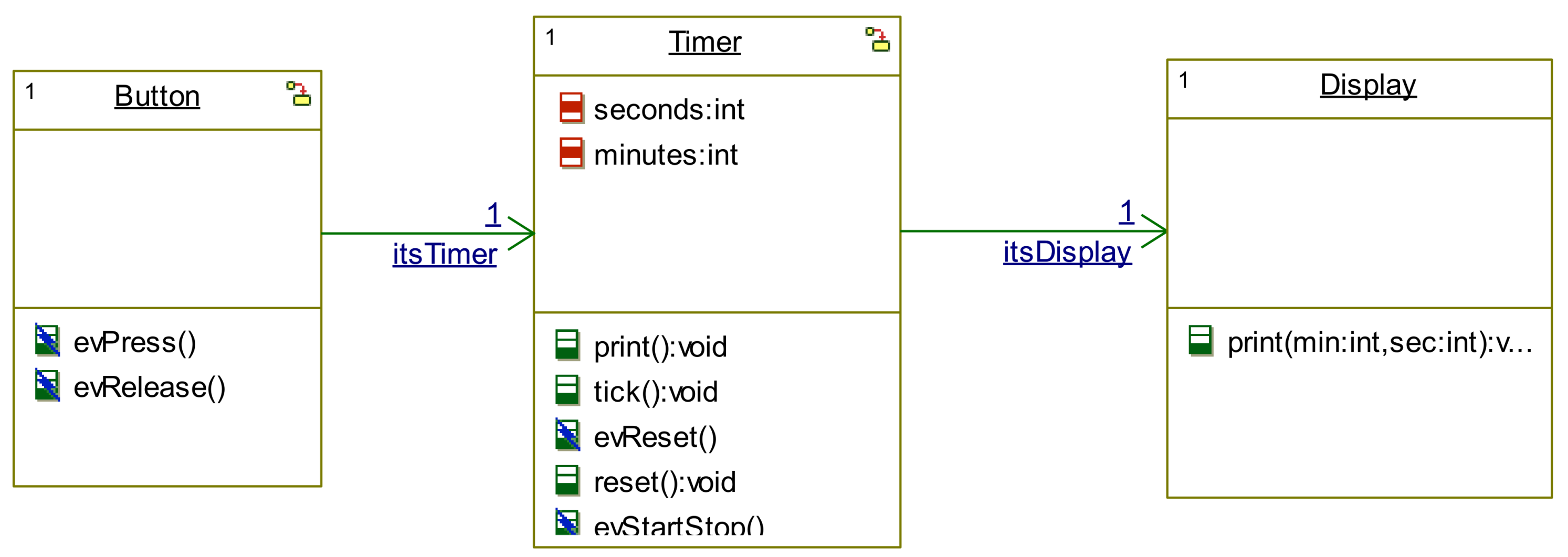
In the UML model of embedded software, events are the most important element for describing software behavior. Most embedded software deals with external events that usually trigger certain software functions. In UML modeling, software behaviors are commonly modeled using state charts; transitions between states are triggered by certain events.
In this lab, as an example of event-driven software modeling, a simple button switch example is studied. The button switch is scanned at 20-ms intervals and an event is generated when the switch is pressed. Figure 5 shows a diagram of the object model and the state charts for the objects of the project. Three light-emitting diodes (LEDs) are sequentially turned on when the button is pressed. To interface with the hardware drivers, the legacy code used in previous labs is combined with the code generated by the model.
● Stopwatch in UML.
In this lab, students are required to complete a stopwatch model and run it on the Linux platform. Students are provided with a basic skeletal model for a stopwatch; they then complete the model and the interface code that allows it to run on the Linux platform. Figure 6 shows a diagram of the stopwatch skeletal object model.
In this lab, button switches and the seven-segment display are used to create the stopwatch. Students are expected to use the object models and hardware interface codes derived in previous labs.
● Elevator Controller in UML
This is the most complex assignment of the course. An elevator simulator that runs on a Windows PC is provided. The PC is equipped with a USB-CAN (Controller Area Network) interface and the elevator is controlled by CAN messages. Figure 7 shows a screenshot of the program. The elevator car can be moved upward, downward, or stopped via CAN messages. When a user presses the call button on a certain floor, the simulator sends a predetermined CAN message. Also, when the elevator car is moving, the simulator sends CAN messages containing current position data at 200-ms intervals.
A general control algorithm for an elevator can be very complicated. To simplify the problem, the operational scenario for this elevator is simplified. It is assumed that the elevator is used only at lunchtime, and that all users wants to descend to the first floor for lunch. It is also assumed that only the down call button of each floor is used. Initially, the elevator is waiting at the first floor. When one of the call buttons is pressed, the car starts moving upward. The rest of the scenario imitates the behavior of a normal elevator.
In this lab, students are required to construct a fully operational model of an elevator controller. As a CAN interface is used to control the elevator simulator on a Windows PC, a basic CAN interface legacy code is provided to the students. Students are expected to build executable code by combining the legacy code and code generated by their model of the elevator controller. Figure 8 shows one possible solution.
Apart from the model-driven method mentioned above, students are required to write a C program for the Cortex-M board to control the same elevator simulator. By doing so, students can compare the model-driven and conventional methods.
4. Student Feedback
This course was offered in the 2018 and 2019 spring semesters. At the end of the semester, students were asked to fill out standardized evaluation forms, which contained 17 standard multiple-choice questions and a space for written comments. Table 2 shows the evaluation data for the questions related to the course content.
In the table, the number in each cell is the number of students who selected that particular choice, and the averages were computed by assigning a score ranging from 1 to 5 to each choice. For each question, the maximum score was 5. The students’ reactions to this course were relatively positive. However, as the student evaluation results show, a few students had difficulty in understanding the course material.
Most students are familiar with basic microprocessor/microcontroller programming, but none, or very few, have encountered a model-driven method. Programming of microprocessors using UML was new to almost all of the students. The final project is the most difficult and not all students finished it. The number of students who finished the final project came to 8 out of 22 students in 2018 and 5 out of 11 students in 2019. Many students adapt to the new programming method quickly, but some found the new concepts to be difficult.
When giving feedback on the final design project, students are requested to complete a table (Table 3 below, with example replies) comparing the conventional and model-driven methods.
Many students commented that an advantage of model-driven design was the associated visualization, especially in terms of architectural design (20 out of 22 students in 2018, 7 out of 11 students in 2019). In addition, they found the state chart detail design very useful; the graphical method allows for intuitive design (14 out of 22 students in 2018, 4 out of 11 students in 2019). Most students were already familiar with a conventional programming language, such as C; the students typically take more than one programming course. Therefore, when students try to program using a model-driven method, they need to change their thinking processes. Our teaching experience suggests that students who wish to engage in serious programming using a model-driven method need to take at least one full course on a modeling language such as UML.
5. Conclusions
Model-driven methods have recently attracted much attention as a means of improving the reliability and efficiency of embedded software design. We describe an embedded software course featuring a model-driven method. The course has been successfully taught twice over the last 2 years; students learn both a new model-driven approach for embedded software design and conventional programming. Although students initially have difficulty in learning and applying the new concepts, most find the new model-driven method attractive because of its visual design. Our teaching experience leads us to believe that a new model-driven method can be incorporated into an embedded software course without compromising conventional content. However, a separate modeling language course may be necessary for those who wish to study a systematic, advanced model-driven method.
Funding
This research was funded by the WC300 Technological innovation R&D program of Small and Medium Business Administration (SMBA, Korea) [S2341060, Development of next generation integrated smart key system based on SoC using IT fusion technology].
Conflicts of Interest
The authors declare no conflict of interest.
References
- Liggesmeyer, P.; Trapp, M. Trends in Embedded Software Engineering. IEEE Softw. 2009, 26, 19–25. [Google Scholar] [CrossRef]
- Sangiovanni-Vincentelli, A.; Di Natale, M. Embedded system design for automotive applications. Computer 2007, 40, 42–51. [Google Scholar] [CrossRef]
- Staron, M. Automotive Software Architectures: An Introduction; Springer International Publishing AG: Basel, Switzerland, 2017; p. 52. [Google Scholar]
- ISO 26262-9:2011(en) Road vehicles—Functional safety—Part 9: Automotive Safety Integrity Level (ASIL)-oriented and safety-oriented analyses. Available online: https://www.iso.org/obp/ui#iso:std:iso:26262:-9:ed-1:v1:en (accessed on 28 August 2019).
- Martin, G. UML for embedded systems specification and design: motivation and overview. In Proceedings of the 2002 Design, Automation and Test in Europe Conference and Exhibition, Paris, France, 4–8 March 2002; pp. 773–775. [Google Scholar]
- Seidewitz, E. What models mean. IEEE Softw. 2003, 20, 26–32. [Google Scholar] [CrossRef]
- France, R.B.; Ghosh, S.; Dinh-Trong, T.; Solberg, A. Model-driven development using UML 2.0: Promises and pitfalls. Computer 2006, 39, 59–66. [Google Scholar] [CrossRef]
- Object Management Group. Available online: http://www.omg.org (accessed on 28 August 2019).
- Running animated models. Available online: https://www.ibm.com/support/knowledgecenter/en/SSB2MU_8.4.0/com.ibm.rhp.animation.doc/topics/rhp_c_dm_rning_anm_models.html (accessed on 28 August 2019).
- Model Based Testing with TestConductor and Automatic Test Generation (ATG). Available online: https://www.ibm.com/support/knowledgecenter/SSB2MU_8.2.1/com.btc.tcatg.user.doc/topics/com.btc.tcatg.user.doc.html (accessed on 28 August 2019).
- Introduction to Microcontroller-Based Systems. Available online: https://ece.osu.edu/courses/introduction-microcontroller-based-systems-2560 (accessed on 28 August 2019).
- Introductory Microcomputer Interfacing Laboratory. Available online: https://www2.eecs.berkeley.edu/Courses/EEC145M/ (accessed on 28 August 2019).
- Design of Microprocessor-Based Systems. Available online: http://eecs.umich.edu/eecs/academics/courses/eecs-373.html (accessed on 28 August 2019).
- Advanced Embedded Software Development. Available online: https://sites.google.com/colorado.edu/ecen5013/home (accessed on 28 August 2019).
- Advanced Embedded Software. Available online: https://my.eng.utah.edu/~cs5785/ (accessed on 28 August 2019).
- Embedded and Real Time Software. Available online: https://cs.brown.edu/courses/csci1600/ (accessed on 28 August 2019).
- Mellor, S.J.; Clark, A.N.; Futagami, T. Model-driven development - Guest editor’s introduction. IEEE Softw. 2003, 20, 14–18. [Google Scholar] [CrossRef]
- Selic, B. The pragmatics of model-driven development. IEEE Softw. 2003, 20, 19–25. [Google Scholar] [CrossRef]
- von Schwerin, M. Software engineering in a nutshell for Electrical Engineering students. In Proceedings of the 2014 IEEE Global Engineering Education Conference (EDUCON), Istanbul, Turkey, 3–5 April 2014; pp. 788–793. [Google Scholar]
- Muppala, J. Experience with an embedded systems software course. ACM SIGBED Review 2005, 2, 29–33. [Google Scholar] [CrossRef] [Green Version]
- Khan, M.U.; Geihs, K.; Gutbrodt, F.; Gohner, P.; Trauter, R. Model-driven development of real-time systems with UML 2.0 and C. In Proceedings of the Fourth Workshop on Model-Based Development of Computer-Based Systems and Third International Workshop on Model-Based Methodologies for Pervasive and Embedded Software (MBD-MOMPES’06), Potsdam, Germany, 30–30 March 2006; pp. 33–42. [Google Scholar] [CrossRef]
- Mura, M.; Sami, M.G. Code Generation from Statecharts: Simulation of Wireless Sensor Networks. In Proceedings of the 2008 11th EUROMICRO Conference on Digital System Design Architectures, Methods and Tools, Parma, Italy, 3–5 September 2008; pp. 525–532. [Google Scholar] [CrossRef]
- Shukla, S.K. Model-Driven Engineering and Safety-Critical Embedded Software. Computer 2009, 42, 93–95. [Google Scholar] [CrossRef]
- IBM Rational Rhapsody. Available online: https://www.ibm.com/support/knowledgecenter/SSB2MU_8.4.0/com.ibm.rhp.homepage.doc/helpindex_rhapsody.html (accessed on 28 August 2019).
- Krasner, J.L. Reducing OEM Development Costs and Enabling Embedded Design Efficiencies Using UML. In Embedded Market Forecasters; American Technology International Inc.: Framingham, MA, USA, 2004. [Google Scholar]
Figure 1.
V-model process.

Figure 2.
Freescale I.MX6Q Cortex-A9 board.

Figure 3.
Software structure: (a) With an operating system; (b) Without an operating system.

Figure 4.
Cortex-M4 microcontroller.

Figure 5.
Object Model Diagram and state chart for the button switch project: (a) Object Model Diagram of the project; (b) State chart for the Button object; (c) State chart for the Led object. (d) State chart for the PushSwitch object.
Figure 5.
Object Model Diagram and state chart for the button switch project: (a) Object Model Diagram of the project; (b) State chart for the Button object; (c) State chart for the Led object. (d) State chart for the PushSwitch object.

Figure 6.
Object Model Diagram of the Stopwatch project.

Figure 7.
Screenshot of the elevator simulator.

Figure 8.
Object Model Diagram and state chart for the elevator controller project: (a) Object Model Diagram of the elevator controller project; (b) State chart for the ElevatorControl object.
Figure 8.
Object Model Diagram and state chart for the elevator controller project: (a) Object Model Diagram of the elevator controller project; (b) State chart for the ElevatorControl object.


Table 1.
Course summary.
| Category | Lecture | Lab |
|---|---|---|
| Conventional Method for Linux | Introduction to Embedded Linux | Embedded Linux Applications Development Environment |
| Real-Time Kernel Concepts | Multi Threads, Semaphore, Mutex | |
| Device Drivers | Applications using LED, FND, and LCD drivers | |
| Linux Architecture | Applications using Interrupt Drivers, Digital Clock, on Embedded Linux | |
| Building a Linux Kernel | Building a Linux Kernel including Device Drivers | |
| Model-driven Method for Linux | Concepts of Model-driven Design | Hello World Example, Counter |
| Concepts of Model-driven Design | Stopwatch | |
| Midterm Exam | ||
| Concepts of Model-driven Design | Linux CAN Communication | |
| Conventional Method for ARM Cortex-M | ARM Cortex-M Processors | Cortex-M serial ports |
| ARM Cortex-M Processors | Cortex-M I2C | |
| ARM Cortex-M Processors | Cortex-M CAN | |
| Final Project (Model-driven and Conventional) | Design Project | Elevator Controller |
| Design Project | Elevator Controller | |
| Design Project | Elevator Controller | |
| Final Exam |
Table 2.
Student evaluation results. (a) 2018; (b) 2019.
(a)
| Questions | SA | A | N | D | SD | AVG |
|---|---|---|---|---|---|---|
| Syllabus was helpful in choosing this course | 13 | 6 | 2 | 1 | 0 | 4.41 |
| Course objectives were concrete and clear | 14 | 4 | 3 | 1 | 0 | 4.41 |
| The instructor effectively presented concepts and techniques | 12 | 7 | 2 | 1 | 0 | 4.36 |
| The instructor provided helpful feedback | 12 | 7 | 2 | 1 | 0 | 4.36 |
| The instructor is enthusiastic about teaching | 12 | 7 | 2 | 1 | 0 | 4.36 |
| The instructor stimulated my interest in the subject matter | 13 | 5 | 3 | 1 | 0 | 4.36 |
| I gained worthwhile knowledge in this course | 14 | 4 | 3 | 1 | 0 | 4.41 |
(b)
| Questions | SA | A | N | D | SD | AVG |
|---|---|---|---|---|---|---|
| Syllabus was helpful in choosing this course | 6 | 3 | 1 | 0 | 1 | 4.18 |
| Course objectives were concrete and clear | 6 | 3 | 1 | 0 | 1 | 4.18 |
| The instructor effectively presented concepts and techniques | 6 | 3 | 1 | 0 | 1 | 4.18 |
| The instructor provided helpful feedback | 5 | 3 | 2 | 0 | 1 | 4.00 |
| The instructor is enthusiastic about teaching | 5 | 3 | 2 | 0 | 1 | 4.00 |
| The instructor stimulated my interest in the subject matter | 5 | 4 | 1 | 0 | 1 | 4.09 |
| I gained worthwhile knowledge in this course | 5 | 4 | 1 | 0 | 1 | 4.09 |
(Key: SA-strongly agree, A-agree, N-neutral, D-disagree, SD-strongly disagree, AVG-average).
Table 3.
Model-driven versus legacy code.
| Model-Driven | Legacy Code (C) | ||
|---|---|---|---|
| Architectural Design | Pros | Visualization | None |
| Cons | Need to learn modeling language | Hard to capture the whole picture | |
| Detail Design | Pros | Intuitive design with state chart | Familiar source code design |
| Cons | Need to learn state chart designs | Difficult to design complex functions | |
| Coding | Pros | Automatic code generation | Flexible |
| Cons | Less flexible Increased code size | Hard to understand code written by other programmers | |
| Debugging | Pros | State chart animation | Familiar source code debugger |
| Cons | Hard to find errors in generated code | No animation |
© 2019 by the author. Licensee MDPI, Basel, Switzerland. This article is an open access article distributed under the terms and conditions of the Creative Commons Attribution (CC BY) license (http://creativecommons.org/licenses/by/4.0/).
Share and Cite
MDPI and ACS Style
Lim, D.-J. Incorporating a Model-Driven Approach into an Embedded Software Course. Electronics 2019, 8, 1004. https://doi.org/10.3390/electronics8091004
AMA Style
Lim D-J. Incorporating a Model-Driven Approach into an Embedded Software Course. Electronics. 2019; 8(9):1004. https://doi.org/10.3390/electronics8091004
Chicago/Turabian StyleLim, Dong-Jin. 2019. "Incorporating a Model-Driven Approach into an Embedded Software Course" Electronics 8, no. 9: 1004. https://doi.org/10.3390/electronics8091004
Note that from the first issue of 2016, this journal uses article numbers instead of page numbers. See further details here.