Smartphone Camera-Based Optical Wireless Communication System: Requirements and Implementation Challenges


Department of Electronics Engineering, Kookmin University, Seoul 02707, Korea
*
Author to whom correspondence should be addressed.
Electronics 2019, 8(8), 913; https://doi.org/10.3390/electronics8080913
Submission received: 22 July 2019
/
Revised: 12 August 2019
/
Accepted: 15 August 2019
/
Published: 19 August 2019
(This article belongs to the Special Issue Visible Light (VLC) and Camera Communication)
Abstract
:Visible light and infrared bands of the optical spectrum used for optical camera communication (OCC) are becoming a promising technology nowadays. Researchers are proposing new OCC-based architectures and applications in both indoor and outdoor systems using the embedded cameras on smartphones, with a view to making them user-friendly. Smartphones have useful features for developing applications using the complementary metal-oxide-semiconductor cameras, which can receive data from optical transmitters. However, several challenges have arisen in increasing the capacity and communication range, owing to the limitations of current cameras and implementation complexities. In this paper, we provide a comprehensive analysis of the OCC technology requirements and opportunities using smartphone cameras from an implementation point of view. Furthermore, we demonstrate an OCC system using a low frame rate smartphone camera to particularly analyze the requirements and critical implementation challenges. Also, some possible solutions are provided with a view to improving the overall system capacity, communication distance, and stability.
1. Introduction
Fifth-generation (5G) technology has not only been characterized with a 10-Gbps data rate but also requires massive user connectivity, internet-of-things (IoT) paradigm, ultra-low power consumptions, and ultra-high security [1]. However, existing RF resources are not enough to support massive user access and IoT paradigm due to limited band and inter channel or inter-symbol interferences. To support the enormous demand for 5G, researchers had to rely on other suitable bands along with the current RF spectrum. The optical spectrum could be a possible solution to the bandwidth problem because it provides a wide range of frequencies (0.3–3000 THz). Optical wireless communication (OWC) technologies, such as visible light communication (VLC), light fidelity, optical camera communication (OCC), and free-space optical communication, can be utilized as ultra-dense small cell networks and high-capacity backhaul support for 5G and beyond. Additionally, OWC can support high data rates [2] and communication distances within a very short to high range [1,3,4,5].
Although OCC does not support high capacity link connectivity due to the camera limitations, it can be employed in numerous low data rate applications, such as indoor positioning, mobile robot navigation, small identification information, and advertisements. As light-emitting diodes (LEDs) are used as transmitters for OCC technology, they can further be used for illumination purposes. These LED lights are fabricated from semiconductor materials, which have fast switching capabilities [6]. Also, cameras are commonly used devices in recent times and they are incorporated into every smartphone. Thus, they are an ideal wireless communication platform, which uses an unlicensed spectrum that provides a very low installation cost and consumes very little energy. In order to support 5G massive connectivity and low power consumption, a large number of users can be connected with the OCC network and access the same information transmitted through light; research for the improvement of this capacity is ongoing. However, due to the existence of smartphones with various operating systems (Android, Windows, or iOS), the same OCC application cannot be used in all types of devices. Among these operating systems, Android has the highest number of users worldwide; thus it has a great prospect for creating applications in this particular area. Moreover, OCC is becoming a promising technology in both indoor and outdoor applications such as localization, smart lighting, patient monitoring, autonomous vehicles, transportation, and augmented reality [1]. However, the implementation of OCC using smartphone cameras is more complicated compared with conventional cameras because current smartphones do not have features that support high data rates and high-speed communication.
The receiver camera can be of two types: global shutter and rolling shutter. In global shutter cameras, the entire frame is exposed at one time; therefore, it captures either the ON or OFF state of an LED. In rolling shutter cameras, the image is captured using row-by-row exposure [7]. For a fixed frame rate, the camera exposure time needs to adjust to cope with the LED’s ON-OFF status and capture a black and white striped image. However, the widths of these strips depend on the frequency of modulation. Most phone cameras use rolling shutter mechanisms and complementary metal-oxide-semiconductor (CMOS) image sensors, owing to the greatly reduced power consumption. In the process of developing smartphone-based OCC technology, several challenges can be faced owing to a limitation of camera frame rate and exposure control of current devices and a lack of suitable modulation schemes. In this study, we analyze the key requirements and challenges in the implementation of an Android smartphone-based OWC system. We provide the necessary experimental results with an Android smartphone to explain why it displayed lower throughput and limited communication distance. We also suggest possible mitigation techniques for these particular challenges. Moreover, we focus on the essential requirements, such as an enhanced data rate and communication distance, flickering mitigation, and multilateral communication with smartphones. The main contributions of this paper can be summarized as follows:
- We provide the OCC architecture in brief and the requirements for the transmitter and receiver design for the system. A discussion on the requirements for designing a flicker-free transmitter and necessary modulations and encoding schemes is also included in this paper.
- Regarding the receiver, the key parameters, limitations, and necessary programming platforms (OpenCV) for modern smartphones are explained in detail.
- We demonstrated an Android application and LED transmitter system to visualize the implementation challenges in real-time communication.
- The key OCC system parameter challenges are analyzed, with possible solutions for issues such as multilateral communication, data rate, communication distance, visual flickering, and user mobility.
- We reviewed the existing deep learning-based real-time object detection techniques-based on their inference time and simplicity. Also, we analyzed opportunities to support user mobility by integrating TensorFlow Lite framework for learning-based LED detection in the OCC application.
The rest of the paper is organized as follows. In Section 2, we provide a brief overview of the OCC system. The transmitter design and requirements are characterized in Section 3. In Section 4, a review of the receiver camera specifications and required processing platforms is provided. In Section 5, the implementation challenges are explained in detail with possible mitigation techniques by applying the real-time OCC system on a smartphone. Section 6 describes the OCC system demonstrated in this paper. Finally, we provide a conclusion to the paper in Section 7.
2. OCC Overview
A detailed and comprehensive study on the introduction to OCC technology is provided in Ref. [8]. In this section, we present a brief overview of the OCC system before discussing its implementation in detail. The OCC system comprises LEDs and image sensors (cameras) which are used as transmitters and receivers, respectively. Moreover, LEDs are used in almost every light-based application, such as indoor illumination, street signals, and car tail lights and headlights [9]. They quickly switch between the ON and OFF states. By employing this property, LED light can be modulated using high frequencies. Figure 1 shows the basic block diagram of an OCC system. Initially, optical channel encoding is performed to detect and correct the error element while transmitting through the channel with noise and interference induced by ambient light sources. Manchester coding (described later) helps to eliminate the light-flickering effect. However, visual flickering may occur if the change in the state of an LED is observed by the human eye (above 200 Hz is considered safe [10]). Further, encoded data is utilized to modulate the LED light at higher frequencies than a camera can detect. Current camera image sensors usually show clear detection of frequency responses up to 6 kHz. All of the tasks are performed by an LED driver circuit, which consists of a high-switching metal-oxide-semiconductor field-effect transistor device, Arduino, and a power supply. Finally, LED light transmits the modulated bits through the optical channel. The receiver extracts the information by capturing and processing the frames with the help of an integrated OpenCV library as an image-processing platform. In a rolling shutter camera, the LED images are captured as bundles of black and white strips. Demodulation is performed on these images by measuring the widths and thresholding of strips. After the demodulation and decoding tasks are completed, the output data is shown on a display.
Smartphone-based real-time processing is a challenging issue as it has camera limitations and lower processing strength. However, in the near future, this technology could provide a large contribution to the upcoming IoT paradigms and the requirements of massive user connectivity. Recently, numerous experimental works have been published [11,12,13,14,15,16,17,18] for OCC with their individual implementation goals. According to the application, every work meets a certain level of results which can satisfy the particular goals. Almost all the experiments are conducted using digital single-lens reflex (DSLR) or smartphone cameras and use MATLAB processing to analyze. Table 1 shows the existing OCC implementation results using smartphone and other DSLR cameras with their challenges and limitations. An RGB LED-based OCC system was proposed by P. Luo et al. [11], where a combined modulation scheme of undersampled phase-shift ON-OFF keying (UPSOOK) and wavelength-division multiplexing (WDM) was used. Although the authors achieved reasonable communication distance, the data rate is limited to bit per second scale only. According to another work of P. Luo et al. [12], a data rate of 500 bps is achieved at a distance of 1.5 m. This work also has to perform off line simulations as well. Multi-level intensity modulation (MI) and color-shift keying (CSK) can provide a comparatively higher data rate (up to 10 kbps) but are limited with the communication distance [14,16,17].
3. OCC Transmitter Characteristics
In OCC systems, the transmitter has low power consumption and is cost-effective because it uses existing lighting equipment such as LEDs. Also, it consists of simple circuitry design and the only requirements are a signal modulator and a power supply. We must select the proper encoding and modulation techniques to ensure a flicker-free light transmission system. The following subsections discuss the types of LEDs used in OCC technology and the existing modulation and encoding techniques, along with their pros and cons.
3.1. Types of LED Transmitters
Either an infrared (IR) or a visible light-based LED transmitter can be used in OCC depending on the application. IR-LED is used for such OCC applications that require non-luminous communication. For example, IR-LED was used for uplink connectivity in the VLC system [19,20]. An advantage of using IR light as a transmitter is that it eliminates the problem of flickering. However, visible LEDs are widely used as OCC transmitters where illumination and communication are both important. We can use existing LEDs as indoor light for indoor localization and other OCC-based applications, street lights and car back lights for OCC-based smart vehicular applications. In this case, flickering can be mitigated using proper changes in the modulation schemes.
3.2. Modulations and Encoding
Modulation is performed in a wireless communication system to transmit data through a defined frequency band. For an OCC system, researchers have developed many modulation techniques to overcome several limitations or to improve system performance, depending on the receiver parameters. Generally, these modulation techniques are divided into three types: screen-modulation, under-sampled modulation, and oversampled modulation [21]. However, screen-based modulation techniques are not preferable because of their short range (10–110 cm) communication system [17]. When the sampling frequency is two times higher than the highest frequency component of the signal, it is termed as oversampling. Binary color-shift keying (BCSK) and rolling shutter-based modulations are types of oversampling techniques in which the scanning rate is very high to achieve improved resolution and data rates. However, these techniques are also restricted by communication distance and mobility support [22,23]. Current commercial cameras are built with low sampling rates which significantly limit the overall data rate for OCC. To deal with this problem, undersampling-based modulation schemes have been introduced. Undersampling is done with necessary changes in OCC to avoid flickering by adopting some subcarrier intensity modulation techniques. Low frame rate (LFR) cameras can easily integrate this modulation technique. The frequency shift on-off keying (FSOOK) modulation technique is the simplest among all the techniques that employ the undersampling mechanism. In this scheme, two frequencies are exploited to represent 1 and 0, called “mark” and “space” [8,21], respectively. One of the frequencies is represented as the integer multiple of the camera frame rate. Figure 2a shows an example in which the mark and space frequencies are 105 and 120 Hz, respectively, with a camera sampling rate of 30 fps. The frame header is used to indicate the start of a data packet. This modulation scheme offers a communication distance, of up to 5 m, although the capacity is very limited [23]. Phase-shift on-off keying (PSOOK) was proposed in Refs. [24,25], employing the undersampling technique. This technique can be utilized to increase the sampling efficiency. Figure 2b shows an example of this scheme in which mark and space frequencies are the same (120 Hz). However, a phase difference was utilized to logically represent 1 and 0. Luo et al. [11] achieved a communication distance of over 60 m using this scheme. However, the achieved data rate was significantly low.
Additionally, an undersampled pulse-position modulation technique was proposed by L. Shangguan et al. [26] to develop cm-level accurate indoor positioning system using OCC. A combined red-green-blue (RGB) color intensity modulation technique was proposed by P. Tian et al. [27], which was able to achieve a data rate of up to 95 kbps over a 1.2 m communication range. According to V.P. Rachim et al. [14], a data rate up of to 10 kbps was developed with a 2 m range using a four-intensity modulation technique. Hence, research is being carried out to develop such modulation schemes for OCC, which can offer both improved capacities and higher communication distances.
Moreover, encoding in communication is a process of changing the original bit sequences to another format for efficient transmission. For OCC technology, the encoding technique can be of two types. The transmission channel can be encoded to detect and eliminate any bit errors through the optical channel. Another technique that is usually used for OCC is a type of line coding called Manchester coding. This encoding allows a transition between the high and low for equal amounts of time within the time period for each bit. Thus, the flickering problem can be eliminated even if a continuous 1 or 0 is transmitted for a long period of time.
4. Smartphone as OCC Receiver
Image sensors cannot have identical characteristics in nature, their imaging quality and behavior vary for different smartphones. Also, a camera’s sampling rate can vary from very low to very high. Moreover, OCC performance such as the data rate and communication distance depends highly on these camera parameters. Cameras with higher sampling rates can offer much higher throughput but these types of cameras are much costlier than those with low sampling rates. The following subsections explain these parameters in detail.
4.1. Frame Rate and Exposure Control
The frame rate is defined as the number of individual frames captured within a single second. Sometimes, there is confusion between frame rate and shutter speed, but shutter speed is referred to as the amount of time for which an individual frame is exposed to light. Exposure time and shutter speed are particularly the same thing, expressed in different ways. Based on the frame rate, cameras rated at higher than 200 fps are considered as high frame rate (HFR) cameras, whereas those rated below 60 fps are classified as LFR cameras. Although HFR cameras promise higher data rates, most of today’s smartphone cameras are of the LFR type and have varying frame rates (24–30 fps) when recoding video. In an OCC system, a light source such as an LED transmits data according to how it is modulated. The receiver camera receives the data by processing its individual image frames. Each frame contains the data in the form of captured LED light. To avoid unexpected interference from the surroundings, each frame should be exposed to light for a very short time which is controlled by the shutter speed of the camera. Therefore, depending on the LED light intensity, an LED image is formed on the image sensor of the camera keeping the low illuminating surroundings dark. This is done for avoiding the complexity of the data recovery and error minimizing.
To implement OCC using a smartphone camera, the frame rate should be fixed at a certain value. Two factors cause frame rate variation: the exposure duration and the focus adjustment. To have a fixed frame rate, the exposure duration should be fixed and the autofocus should be locked. Android versions up to 4.4 (camera application programming interfaces (APIs)) do not support exposure control. Only the camera2 API has additional features, such as manually-controlled exposure, focus, raw capture etc. Also, cameras should open on a secondary handler thread and the camera2 API makes thread management easier.
4.2. Rolling Shutter Effect
Currently, most consumer cameras contain CMOS sensors, which include rolling shutter mechanisms. The sequential readout technique is a key feature of rolling shutter cameras in which frames are not captured at exactly the same instant [7]. The scene is captured by rapid scanning, either horizontally or vertically, unlike a global shutter camera, in which the complete scene is captured at the same time. Because a global shutter camera allows its sensor to be exposed to light once, it can hold either the ON or OFF state of an LED in a single frame. In a rolling shutter camera, each row of pixels is exposed simultaneously at the exposure time. The readout time protects the rows of pixels from overlapping. In a single captured image, the rolling shutter allows multiple exposures. This enables multiple LED states to be obtained at the same time in a single frame as each row is exposed once to light. Therefore, for an LED, that flickers on and off according to the modulated binary bit stream, the captured image contains a bunch of black and white strips. The strip widths depend on the modulation frequencies, and the number of strips depends on the distance between the camera and LED. Figure 3 shows the image formation technique in a rolling shutter camera. Here the LED status is defined using the black and white blocks and the captured LED image is shown after it is rotated 270º clockwise. For example, the region is marked in the image to show what happens during the exposure time for row n and row n+1. In the second case, we get a transition region for the LED between ON and OFF, as it changes its state during the exposure time.
4.3. Image Processing Platform (Android with OpenCV)
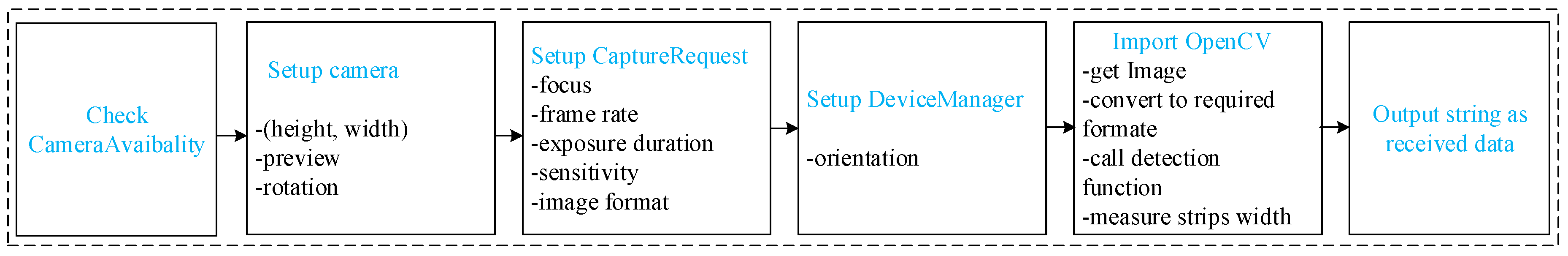
For real-time OCC applications, smartphone devices should perform fast processing of the received image information. Because the frame rate needs to be fixed for a smartphone camera, real-time processing should be completed within the individual frame duration. If Rf is the frame rate of the camera, then 1/Rf is the time limit for each frame in real-time. All smartphone cameras are rolling shutter type and captured images are scanned row by row. Generally, for an Android smartphone-based OCC system, an application needs to be developed with the help of OpenCV to process the captured image and extract data. OpenCV is a library of programming functions which mainly handles real-time computer vision and it can be easily integrated with Android studio. To develop such a real-time application with Android Studio and OpenCV, we have to follow the step by step procedure that is described in Figure 4.
Initially, a camera permission setup is needed to build any camera-based application. Also the API should be higher than level 21 to use camera2 packages. The camera setup is required to define the window size and preview management. Because camera2 packages support dynamic exposure and frame rate control, we need to set the CaptureRequest such as camera focus, frame rate, exposure duration, sensitivity, and image format. The device orientation needs to be fixed using the DeviceManager function. The LED image can be processed to get information using the OpenCV library, which helps to obtain an image and convert it to required formats. An image detection function should be developed to perform LED stripe width measurements. Moreover, the OpenCV library is integrated with this platform to provide pixel reading, thresholding, and object detecting functionalities. Some of the Android features described in this study are used to create the camera device and process the requests. One request acts to capture a single frame and output a set of image buffers for the request. A CameraManager class is required when multiple requests are in the queue, to maintain the full frame rate. The image data is encapsulated in Image objects and can be directly accessed through a class named ImageReader using a YUV_420_888 format. Initially, the camera shutter speed is controlled to focus only on the white LEDs and to detect only the region of interest (RoI). To extract the transmitted bit stream, the first thing that needs to be found is the header, followed by the original payload. As the widths of the strips vary with frequencies, we can determine the frequencies that the received signal contains by measuring the stripe width. Finally, after completing the image detection and data extraction, the received information can be displayed.
5. Implementation Challenges
The previous section describes the overall requirements of a smartphone-based OCC system. In this section, the key challenges and limitations of this system are addressed by demonstrating an android smartphone-based OCC system. The detailed demonstration methodology and test bed are explained in Section 6. These challenges include low data rates, short distance communication, multilateral communication, visual flickering, and user mobility support. These challenges arise owing to the limitations of sampling rate, exposure control, and processing speed of current smartphone cameras. We discuss the major challenges and techniques for their possible remedies in the following subsections.
5.1. Visual Flickering
OCC technology can suffer from visual flickering. Visual flickering occurs when a change in LED brightness (depending on modulation frequency) is perceived by the human eye. In general, frequencies greater than 200 Hz are considered safe [10]. Lower carrier frequencies allow LEDs to turn on and off for longer periods of time, whereas higher carrier frequencies allow it for a very short period of time. The flickering of an LED also depends on its circuital properties. In an OCC demonstration, the LED driver and its circuitry have to support the required fast switching between the ON and OFF states. Visual flickering may cause some biological problems or even health issues. Neurological problems, headaches, fatigue blurred vision, eyestrain, and reductions in visual task performance can occur from continuous visual flickering. For that reason, when implementing any OCC system, the flickering issue should be kept in mind. Figure 5 illustrates the variation in the ON and OFF times of an LED when captured using a rolling shutter camera with a variation in carrier frequency. The widths of the strips decrease as the carrier frequency increases. We used an LED of 9 cm diameter and transmitted digital bits with carrier frequencies from 200 Hz to 6000 Hz. Also, we set the frame rate and exposure duration of the camera to the values of 20 fps and 1/8000 sec respectively. The camera could successfully decode the received information to a maximum of 6000 Hz because of a limitation in the number of pixels on the image sensor. Differentiating between 1 and 0 bits becomes difficult in this situation, because the width of the individual On-OFF state comprises less than 1 pixel. However, at lower frequencies of around 200 Hz, width detection for the purpose of decoding becomes very easy but increases the risk of causing visual flickering. In this case, the width becomes larger and the human eye can differentiate the state change between ON and OFF. After considering both these limitations, researchers are interested to use modulation frequency between (1 to 5) kHz [23].
5.2. Multilateral Communication
OCC technology is expanding its application toward both indoor and outdoor systems, such as mobile robot localization and navigation, and V2X communications. In those systems, the camera needs to communicate with multiple LEDs. However, challenges such as low frame rates, function overloading, and slow processing arise when smartphones try to establish multiple communication links between the LEDs and camera. To achieve the multilateral communication, the first requirement is to detect and track each LED. Also, the positions of the LEDs on the image sensor can change because the user can be in a mobile condition. Therefore, the Android application needs to record the pixel values and compare between previous and present pixel values to track the detected LEDs. The second requirement is to measure the stripe widths to extract the transmitted frequencies and demodulate the received payload. Sometimes, function overloading occurs when the input to the processing unit overloads the system capacity. In Figure 6, the limitations behind the multiple object detections and processing in real-time are explained. The main objective is getting the stripe widths, which can be detected individually but require higher processing time (Figure 6a). However, detection of all the strips of an LED can be processed using comparatively less time (Figure 6b). In the latter case, a rectangle is drawn that meets the edge region of the LED, and a straight line is considered as a reference to obtain the widths of the strips.
Therefore, the total time to detect and track each LED and the time to demodulate the received signal should be within the frame processing time.
5.3. Data Rate
OCC is considered as a promising technology for low data rate applications, such as vehicular communications and indoor positioning and navigation. There are a number of factors that limit the data rate of this system. Specially, the data rate depends on technical factors such as modulation frequencies, frame rate, shutter speed, signal-to-noise ratio (SNR), and spatial distortion. Because almost every smartphone camera is rated with LFR ranges between 20 and 60 fps, it is required to allocate the transmitted symbol rate within at least half the region of the frame rate to decode the received data [28]. Therefore, a higher frame rate (i.e., within the 1000 fps range) enables us to capture a higher number of transmitted bits, and thus, increases the data rate. However, this is not currently available from a regular user point of view. By controlling the exposure time of the camera, we can develop a noise-free receiver. To ensure a healthier data rate, researchers are concentrating on developing new modulation techniques as mentioned in Section 3. However, the data rate cannot be achieved at the desired level when implemented on a smartphone camera platform because of the existing limitations on frame rate and processing speed. As a solution to overcoming this data rate shortage, data can be received from multiple LEDs simultaneously, an operation known as MIMO. According to the work of L. Zeng et al. [3], the authors have verified the data rate up to the Gbps range through simulation. They considered the optical MIMO operation using an imaging diversity receiver. Some RGB LED-based intensity modulation techniques have been developed to increase the data rate up to the several kbps range while implementing with the smartphone, but it exhibits limited communication distance [29]. Using the color intensity modulation technique, rates of up to 95 kbps have been achieved by a 330 fps camera, which also requires a PC for processing [27]. However, this OCC technique limits the communication range to 1.5 m, which is not very effective in real-time OCC-based applications. Current smartphone versions cannot support this high frame rate for real-time data receptions. Still, it remains challenging to develop MIMO using smartphones to overcome the processing time limitations because real-time detection and tracking are needed to support mobility.
5.4. Communication Range
The distance between the transmitter and receiver is considered as an important parameter for evaluating the performance of a camera-based optical communication system. Recently, researchers have been trying to find solutions to increase the communication link range [28,29,30,31]. They have tried to apply various light modulation techniques, but the distance also depends on the LED size and pixel size in some cases. Figure 7 describes the captured LED images at various distant LED positions. We can see that for the nearest LED, the covered pixel area on the image sensor is larger than the farthest one, although the actual sizes of the LEDs are the same, which is described in Chen, H.W et al. [16] as well. However, the strip’s widths do not change with the variation in distance between transmitter and receiver because the light ON-OFF time remains the same. Therefore, the LED situated at the greater distance occupies a limited number of black and white strips. We use UFSOOK modulation to experimentally observe the distance variation between the LED and the camera, and the variation in the number of strips. We observe 26, 18, and 9 strips at LED distances of 0.5, 2.0, and 4.0 m, respectively (2 and 4 kHz are used for the ON and OFF conditions of an LED, respectively), as shown in Figure 7. Earlier in Section 3, we describe that when Manchester line coding is used and a digital 1 or 0 is transmitted, the LED state is changed twice per bit. As a result, the captured image on the image sensor consists of two strips per bit. Therefore, we can say that at least three strips are needed on the image sensor to extract the received data. This problem limits the communication distance for a smartphone-based OCC system. We experimentally found that an LED of 9 cm diameter provides the minimal required number of strips at a maximal distance of 5 m. Therefore, the communication distance can be increased if a larger LED is used for this system. Another solution to increase the communication range is increasing the modulation frequency. However, synchronization with the sampling rate is also needed. We experimentally evaluated the variation in the number of strips with the change in distance between the camera and LED, as shown in Figure 8. Here, we take three LEDs with surface areas corresponding to diameters of 6, 9.5, and 14 cm. It is usual for a larger LED to have a higher number of strips and provide a longer communication distance for the same transmitted bit frequency. In Figure 8a,b, we considered two different carrier frequencies of 3 and 5 kHz, respectively. Because a higher frequency causes reduced stripe widths, it can provide a higher number of LED ON-OFF strips. If frequency synchronization with the camera sampling rate can be confirmed, then this higher carrier frequency should also provide a higher communication distance. Furthermore, we provide a comparison between the maximal communication ranges for these different-sized LEDs with respect to the two individual frequencies (3 and 5 kHz) in Figure 9. This figure depicts that the 14 cm diameter LED can provide maximal range that is twice as long for 5 kHz as it is for 3 kHz. However, existing cameras can only differentiate the black and white strips of frequency that are not higher than 6 kHz because of the limitation of unit pixel size. Beyond that frequency, the LED will switch very quickly between the ON and OFF states, which will result in greatly reduced strips widths that are even smaller than the unit pixel width.
5.5. User Mobility
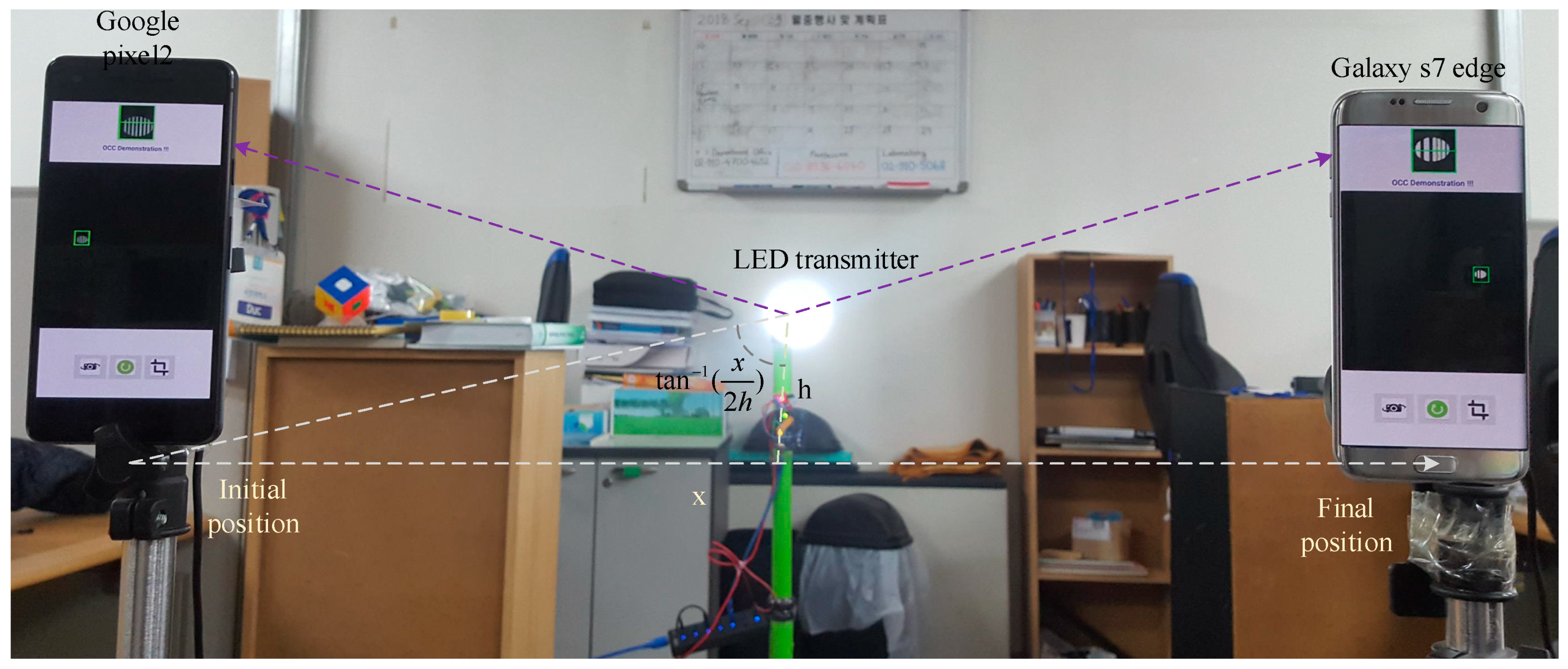
It is crucial that the smartphone-based OCC system should support user mobility. In the static condition, a user can get the data from LED regardless of the processing time dependency. However, when a user is in the mobile state, the user’s maximum speed depends on the total processing time to get the information from the LED. Figure 10 illustrates the concept practically. Suppose the mobile user of Google pixel 2 is at the initial position and moves to its final position at the user of Galaxy s7 edge. Meanwhile, the user covers the distance x. The LED image on the image sensor also moves from left to right as shown in the figure. Hence, to cover the distance x, the user’s velocity can be increased if efficient processing is ensured to minimize the total processing time. Besides, LED detection and tracking is needed to accept mobility, and this requires extra processing time as well [23,32]. It is realized experimentally, that for a 20 fps camera, each frame requires 20 ms additional time to detect and track LEDs inside the camera field-of-view (FoV). Another dependency of mobility support arises when the user moves from one LED field to another. In this case, a new LED enters to the camera FoV and the user will receive new data without affecting the OCC performance. However, the previous LED information can be removed if there is no data-storing system associated with the application. Since LED detection and tracking in real-time are considered as a major challenge in OCC mobility support, we investigate conventional object detection methods and their relative processing time in the following subsections. Later, we discuss new opportunities to build an Android learning-based detection platform with the existing OCC application which is TensorFlow Lite.
5.5.1. Object Detection Methods
Android-based object recognition requires fast learning from a pre-trained model, classification, and detection from a real-time video. There are existing deep neural network-based detection techniques that can be used for real-time video processing that are tabulated in Table 2. Faster region-convolutional neural network (R-CNN) and mask R-CNN are conceptually similar. The only difference is that in mask R-CNN, a segmentation mask is added on each RoI along with the bounding boxes which facilitates the extensive usage. Spatial Pyramid Pooling network (SPP-net) can generate a fixed-length representation regardless of image size or scale. In this system, the feature maps of a convolution layer are fed into an SPP-layer, which then represents fixed-length outputs to fully-connected layers.
You only look once v3 (YOLOv3) is an entirely different method of object detection where it passes the whole image only once, the same as the single-shot multi-box detector (SSD). In this process, the image is divided into a grid of cells which depend on the size of the input image. Each cell is responsible for predicting the number of boxes in the image. Then, the confidence of prediction is performed for each of the boxes. Finally, boxes of lower values are eliminated using non-maximum suppression technique. The SSD is a simple, faster and comparably more accurate method. It eliminates both proposal generation and resampling stages and encapsulates a single detector which makes it simple for training and testing.
5.5.2. Tensorflow Lite for Android
Mobile processing units are linked with a large computational overhead; consequently, it requires a software which is computationally simple, uses minimum load, and reduced execution time. TensorFlow Lite is a lightweight framework of TensorFlow for mobile and embedded devices developed by Google for fast mobile inference on small devices. Android 8.1 or API level 27 as well as their higher versions are linked with Android neural network API for hardware acceleration and are supported by TensorFlow Lite. TensorFlow Lite can utilize those pre-trained models on MobileNets to perform several selective tasks such as object detection, face attributes detection, fine-grained classification, and landmark recognition. To use TensorFlow Lite in Android Studio, one has to include the library in build.gradle dependencies as “compile‘org.tensorflow:tensorflow-lite: + ”. It enables user to import the TensorFlow Lite interpreter into the OCC application to detect particular LEDs while in a mobile situation.
6. Demonstration of OCC
We demonstrate an OCC system using Android smartphone to illustrate the implementation challenges more visibly. The camera and transmitter configurations are listed in Table 3. On the transmitter side, we use a single, circular LED of 15 W power with a surface diameter of 14 cm as the OCC transmitter. Arduino uno was programmed to switch the LED at the transmitting frequency. FSOOK modulation was used and we defined 2 and 4 kHz to transmit bits 1 and 0. Multiple users can be connected to the same LED as shown in Figure 10. The Android application was developed in Android Studio for the API 26 which supports exposure and frame control. To facilitate LED detection and width measurement, we had to control the camera exposure to a very low value and in our case we fixed it to 1/8000 s. Two different types of Android phones were used to receive data from LED. The image view is given with a height of 800 px and width of 600px. We selected a fixed RoI for the detected LED and processed the images using OpenCV320 library.
Initially, we detected the width of the strips and measured the frequencies that are allocated for the individual bits 1 and 0. The extracted digital bits were then converted to the received text format that is “OCC Demonstration !!!”. The total time required to extract this information was 45 milliseconds per frame, and we were able to communicate within the maximal range of 7.5 m. However, this system provides low data rate due to the limitation of frame rate and increased processing time for each frame. The demonstration shows that the OCC application is running on two different smartphones. However, it still needs some changes on threshold value due to the non-identical characteristics of image sensors of the different smartphones. The current OCC system does not support the required level of mobility support, which is one of the key requirements.
Although the requirements and implementation challenges are described in Section 5 in detail, we can summarize the limitations with the possible solution issues as follows.
- To mitigate visual flickering in the transmitter, modulation frequencies should be used within the range of 1~5 kHz. In our demonstration, we used 2 & 4 kHz for FSOOK modulation.
- Achieving data from multiple LEDs requires fast processing to measure strips width. Readers can look into our previous work [23] regarding achieving multilateral data reception from multiple fixed receiving windows. Here the challenging issue is achieving mobility support, which can be eliminated by developing both LED detection and data reception in smartphones. We can use TensorFlow Lite for smartphone for this purpose in future which is currently under development by Google.
- The data rate can be increased by adopting several hardware and technical considerations. We explained that in detail in Section 5.3. We hope in future we can develop smartphones with a higher frame rate and greater image sensor resolution to support the required data rate.
- Communication range of an OCC system mostly depends on the data transmission frequency, LED and pixel size. Experimentally, we showed the communication range variation with the change of LED size and frequency.
7. Conclusions
Implementation of an OCC system using a smartphone is quite a challenging task due to the existing limitations of the smartphone camera specifications, which limit the overall system capacity and communication distance. The main objective of this paper is to address the real-time implementation challenges of such systems and also carry out comprehensive analysis as part of this work. Furthermore, we compare the existing modulation schemes with respect to their particular advantages and limitations. We also demonstrate an Android camera-based application and a transmitter system using FSOOK to analyze the requirements and difficulties in implementing an OCC system for smartphone cameras. This system had a maximal communication range of 7.5 m. Specifically, we analyzed the major challenges such as flickering, multilateral communication, communication distance, data rate, and user mobility support. Moreover, we provided some possible solutions to increase system performance.
Author Contributions
All authors have significant contribution in this paper. Specifically, Conceptualization and methodology, M.S.; software, M.K.H. and M.Z.C.; validation, M.S., M.K.H. and M.Z.C.; formal analysis, M.Z.C.; investigation, M.Z.C., Y.M.J.; resources, M.S.; data curation, M.S., M.K.H.; writing—original draft preparation, M.S.; writing—review and editing, all authors; visualization, M.S., M.Z.C.; supervision, M.Z.C. and Y.M.J.; project administration, Y.M.J.; funding acquisition, Y.M.J.
Funding
This research was supported by the MSIT (Ministry of Science and ICT), Korea, under the ITRC (Information Technology Research Center) support program (IITP-2018-0-01396) supervised by the IITP (Institute for Information & communications Technology Promotion).
Conflicts of Interest
The authors declare no conflict of interest.
References
- Chowdhury, M.Z.; Hossan, M.T.; Islam, A.; Jang, Y.M. A comparative survey of optical wireless technologies: Architectures and applications. IEEE Access 2018, 6, 9819–9840. [Google Scholar] [CrossRef]
- Hossan, M.T.; Chowdhury, M.Z.; Islam, A.; Jang, Y.M. A novel indoor mobile localization system based on optical camera communication. Wirel. Commun. Mob. Comput. 2018, 2018, 9353428. [Google Scholar] [CrossRef]
- Zeng, L.; O’Brien, D.C.; Le Minh, H.; Faulkner, G.E.; Lee, K.; Jung, D.; Oh, Y.; Won, E.T. High data rate multiple input multiple output (MIMO) optical wireless communications using white LED lighting. IEEE J. Sel. Areas Commun. 2009, 27, 1654–1662. [Google Scholar] [CrossRef]
- Hossan, M.; Chowdhury, M.Z.; Hasan, M.; Shahjalal, M.; Nguyen, T.; Le, N.T.; Jang, Y.M. A new vehicle localization scheme based on combined optical camera communication and photogrammetry. Mob. Inf. Syst. 2018, 2018, 8501898. [Google Scholar] [CrossRef]
- Hasan, M.K.; Chowdhury, M.Z.; Shahjalal, M.; Jang, Y.M. Fuzzy based network assignment and link-switching analysis in hybrid OCC/LiFi system. Wirel. Commun. Mob. Comput. 2018, 2018, 2870518. [Google Scholar] [CrossRef]
- Nakazawa, Y.; Makino, H.; Nishimori, K.; Wakatsuki, D.; Komagata, H. Indoor positioning using a high-speed, fish-eyelens-equipped camera in visible light communication. In Proceedings of the Fourth International Conference on Indoor Positioning Indoor Navigation, Montbeliard-Belfort, France, 24 May 2013. [Google Scholar]
- Lee, H.Y.; Lin, H.M.; Wei, Y.L.; Wu, H.I.; Tsai, H.M.; Lin, K.C. RollingLight: Enabling line-of-sight light-to-camera communications. In Proceedings of the Thirteenth Annual International Conference on Mobile Systems (ACM MobiSys), Florence, Italy, 18–22 May 2015. [Google Scholar]
- Ghassemlooy, Z.; Luo, P.; Zvanovec, S. Optical camera communications. In Optical Wireless Communications; Uysal, M., Capsoni, C., Ghassemlooy, Z., Boucouvalas, A., Udvary, E., Eds.; Springer: Cham, Switzerland, 2016; pp. 547–568. [Google Scholar]
- Saha, N.; Ifthekhar, M.S.; Le, N.T.; Jang, Y.M. Survey on optical camera communications: Challenges and opportunities. IET Optoelectron. 2015, 9, 172–183. [Google Scholar] [CrossRef]
- Berman, S.M.; Greenhouse, D.S.; Bailey, I.L.; Clear, R.D.; Raasch, T.W. Human electro retinogram responses to video displays, fluorescent lighting, and other high frequency sources. Optom. Vis. Sci. 1991, 68, 645–662. [Google Scholar] [CrossRef] [PubMed]
- Luo, P.; Zhang, M.; Ghassemlooy, Z.; Le Minh, H.; Tsai, H.M.; Tang, X.; Png, L.C.; Han, D. Experimental demonstration of RGB LED-based optical camera communications. IEEE Photonics J. 2015, 7, 1–12. [Google Scholar] [CrossRef]
- Luo, P.; Zhang, M.; Ghassemlooy, Z.; Le Minh, H.; Tsai, H.M.; Tang, X.; Han, D. Experimental demonstration of a 1024-QAM optical camera communication system. IEEE Photonics Technol. Lett. 2016, 28, 139–142. [Google Scholar] [CrossRef]
- Lin, B.; Ghassemlooy, Z.; Lin, C.; Tang, X.; Li, Y.; Zhang, S. An indoor visible light positioning system based on optical camera communications. IEEE Photonics Technol. Lett. 2017, 29, 579–582. [Google Scholar] [CrossRef]
- Rachim, V.P.; Chung, W. Multilevel intensity-modulation for rolling shutter-based optical camera communication. IEEE Photonics Technol. Lett. 2018, 30, 903–906. [Google Scholar] [CrossRef]
- Lain, J.; Jhan, F.; Yang, Z. Non-line-of-sight optical camera communication in a heterogeneous reflective background. IEEE Photonics J. 2019, 11, 1–8. [Google Scholar] [CrossRef]
- Chen, H.W.; Wen, S.S.; Wang, X.L.; Liang, M.Z.; Li, M.Y.; Li, Q.C.; Liu, Y. Color-shift keying for optical camera communication using a rolling shutter mode. IEEE Photonics J. 2019, 11, 1–8. [Google Scholar] [CrossRef]
- Boubezari, R.; Le Minh, H.; Ghassemlooy, Z.; Bouridane, A. Smartphone camera based visible light communication. J. Lightwave Technol. 2016, 34, 4121–4127. [Google Scholar] [CrossRef]
- Cahyadi, W.A.; Kim, Y.H.; Chung, Y.H.; Ahn, C. Mobile phone camera-based indoor visible light communications with rotation compensation. IEEE Photonics J. 2016, 8, 1–8. [Google Scholar] [CrossRef]
- Karunatilaka, D.; Zafar, F.; Kalavally, V.; Parthiban, R. LED based indoor visible light communications: State of the art. IEEE Commun. Surv. Tutor. 2015, 17, 1649–1678. [Google Scholar] [CrossRef]
- Bui, T.; Kiravittaya, S. Demonstration of using camera communication based infrared LED for uplink in indoor visible light communication. In Proceedings of the Sixth International Conference on Communications and Electronics (ICCE), Ha Long, Vietnam, 27–29 July 2016. [Google Scholar]
- Luo, P.; Zhang, M.; Ghassemlooy, Z.; Zvanovec, S.; Feng, S.; Zhang, P. Undersampled-based modulation schemes for optical camera communications. IEEE Commun. Mag. 2018, 56, 204–212. [Google Scholar] [CrossRef]
- Roberts, R.D. Undersampled frequency shift ON-OFF keying (UFSOOK) for camera communications (CamCom). In Proceedings of the 22nd Wireless and Optical Communication Conference, Chongqing, China, 16–18 May 2013. [Google Scholar]
- Shahjalal, M.; Hossan, M.; Hasan, M.; Chowdhury, M.Z.; Le, N.T.; Jang, Y.M. An implementation approach and performance analysis of image sensor based multilateral indoor localization and navigation system. Wirel. Commun. Mob. Comput. 2018, 2018, 7680780. [Google Scholar] [CrossRef]
- Luo, P.; Ghassemlooy, Z.; Le Minh, H.; Tang, X.; Tsai, H. Undersampled phase shift ON-OFF keying for camera communication. In Proceedings of the Sixth International Conference on Wireless Communications and Signal Processing (WCSP), Hefei, China, 23–25 October 2014. [Google Scholar]
- Kim, B.W.; Jung, S. Novel flicker-free optical camera communications based on compressed sensing. IEEE Commun. Lett. 2016, 20, 1104–1107. [Google Scholar] [CrossRef]
- Shangguan, L.; Zhou, Z.; Yang, Z.; Liu, K.; Li, Z.; Zhao, X.; Liu, Y. Towards accurate object localization with smartphones. IEEE Trans. Parallel Distrib. Syst. 2013, 25, 2731–2742. [Google Scholar] [CrossRef]
- Tian, P.; Huang, W.; Xu, Z. Design and experimental demonstration of a real-time 95kbps optical camera communication system. In Proceedings of the 10th International Symposium on Communication Systems, Networks and Digital Signal Processing (CSNDSP), Prague, Czech Republic, 20–22 July 2016. [Google Scholar]
- Luo, P.; Jiang, T.; Haigh, P.A.; Ghassemlooy, Z.; Zvanovec, S. Undersampled pulse width modulation for optical camera communications. In Proceedings of the IEEE International Conference on Communications Workshops (ICC Workshops), Kansas City, MO, USA, 20–24 May 2018. [Google Scholar]
- Chen, S.; Chow, C. Color-shift keying and code-division multiple-access transmission for RGB-LED visible light communications using mobile phone camera. IEEE Photonics J. 2014, 6, 1–6. [Google Scholar] [CrossRef]
- Li, Y.; Ghassemlooy, Z.; Tang, X.; Lin, B.; Zhang, Y. A VLC smartphone camera based indoor positioning system. IEEE Photonics Technol. Lett. 2018, 30, 1171–1174. [Google Scholar] [CrossRef]
- Yang, Y.; Hao, J.; Luo, J. CeilingTalk: Lightweight indoor broadcast through LED-camera communication. IEEE Trans. Mob. Comput. 2017, 16, 3308–3319. [Google Scholar] [CrossRef]
- Jadhav, S.P.; Tomy, S.; Jayswal, S.S.; Dhaware, H.D.; Vijapure, A.R. Object detection in android smartphone for visually impaired users. Int. J. Adv. Res. Comput. Commun. Eng. 2016, 5, 332–334. [Google Scholar]
- Ren, S.; He, K.; Girshick, R.; Sun, J. Faster RCNN: Towards real-time object detection with region proposal networks. In Proceedings of the Twenty-eighth International Conference on Neural Information Processing Systems, Montreal, QC, Canada, 8–13 December 2015. [Google Scholar]
- He, K.; Gkioxari, G.; Dollar, P.; Girshick, R. Mask R-CNN. arXiv 2017, arXiv:1703.06870. [Google Scholar]
- He, K.; Zhang, X.; Ren, S.; Sun, J. Spatial pyramid pooling in deep convolutional networks for visual recognition. In Proceeding of the Thirteenth European Conference on Computer Vision, Zurich, Switzerland, 6–12 September 2014. [Google Scholar]
- Dai, J.; Li, Y.; He, K.; Sun, J. R-FCN: Object Detection via Region-Based Fully Convolutional Networks. arXiv 2016, arXiv:1605.06409. [Google Scholar]
- Lin, T.-Y.; Dollar, P.; Girshick, R.; He, K.; Hariharan, B.; Belongie, S. Feature pyramid networks for object detection. In Proceedings of the Conference on Computer Vision and Pattern Recognition, Honolulu, HI, USA, 21–26 July 2017. [Google Scholar]
- Liu, W.; Anguelov, D.; Erhan, D.; Szegedy, C.; Reed, S. SSD: Single Shot Multibox Detector. arXiv 2015, arXiv:1512.02325. [Google Scholar]
- Redmon, J.; Farhadi, A. Yolov3: An Incremental Improvement. arXiv 2018, arXiv:1804.02767. [Google Scholar]
Figure 1.
The block diagram of an optical camera communication (OCC) transmitter and receiver system.
Figure 1.
The block diagram of an optical camera communication (OCC) transmitter and receiver system.

Figure 2.
An example of undersampling-based modulation schemes for OCC systems [8]. (a) FSOOK, (b) PSOOK.
Figure 2.
An example of undersampling-based modulation schemes for OCC systems [8]. (a) FSOOK, (b) PSOOK.

Figure 3.
LED image capturing mechanisms for a rolling shutter camera [7].
Figure 3.
LED image capturing mechanisms for a rolling shutter camera [7].

Figure 4.
Procedure for getting and processing images in Android Studio using OpenCV.

Figure 5.
Captured LED images for various transmitted frequencies.

Figure 6.
Multiple object detection. (a) Individual stripe detection of a single LED (requires much processing time). (b) A single LED detection using a rectangle (requires less processing time). (c) Multiple object detection using a rectangle (optimum).
Figure 6.
Multiple object detection. (a) Individual stripe detection of a single LED (requires much processing time). (b) A single LED detection using a rectangle (requires less processing time). (c) Multiple object detection using a rectangle (optimum).

Figure 7.
Distance problem visualization for a smartphone-based OCC system. (a) LEDs at various distances, (b) image of LEDs after changing the exposure duration to 1/8000 s.
Figure 7.
Distance problem visualization for a smartphone-based OCC system. (a) LEDs at various distances, (b) image of LEDs after changing the exposure duration to 1/8000 s.

Figure 8.
Variation in the number of strips with communication range for a CMOS camera at a transmitted bit frequency of (a) 3 kHz, and (b) 5 kHz.
Figure 8.
Variation in the number of strips with communication range for a CMOS camera at a transmitted bit frequency of (a) 3 kHz, and (b) 5 kHz.

Figure 9.
Variation of communication range with the variation of modulation frequency and change of LED size.
Figure 9.
Variation of communication range with the variation of modulation frequency and change of LED size.

Figure 10.
Demonstrations of the OCC using Google pixel2 and Samsung Galaxy s7 edge smartphone.


Table 1.
Survey of the existing optical camera communication (OCC) implementations with their limitations and challenges.
Table 1.
Survey of the existing optical camera communication (OCC) implementations with their limitations and challenges.
| Article | Implementation Direction | Achievement | Limitations/Challenges |
|---|---|---|---|
| [11] | RGB LED-based Optical camera (DSLR) communication using UPSOOK and WDM |
|
|
| [12] | Dual LED-based optical camera (Canon 700D) communication using 1024 – QAM. |
|
|
| [13] | Indoor positioning using optical camera (Canon EOS 7D) communication |
|
|
| [14] | Optical camera (smartphone) communication using four-level intensity modulation. |
|
|
| [15] | Smartphone (Galaxy s6) based NLOS OCC. |
|
|
| [16] | OCC using color-shift keying modulation |
|
|
| [17] | Screen to smartphone camera communication using VLC |
|
|
| [18] | Indoor VLC using mobile phone camera |
|
|
Table 2.
Real-time object detection methods with their inference time.
| Methods | Detection Procedures | Frameworks | Inference Time | Language |
|---|---|---|---|---|
| Faster R-CNN [33] | RPN | Caffe | 0.2 s | Python/ MATLAB |
| Mask R-CNN [34] | RPN | TensorFlow/ Keras | 0.35–2 s | Python |
| SPP-net [35] | Edge Boxes | Caffe | 0.4 s | MATLAB |
| R-FCN [36] | RPN | Caffe | 0.1 s | MATLAB |
| FPN [37] | RPN | TensorFlow | 0.2 s | Python |
| SSD [38] | - | Caffe | 0.15 s | C++ |
| YOLOv3 [39] | - | Darknet | 0.05 s | C |
Table 3.
Experimental parameters.
| Parameters | Values |
|---|---|
| LED | 15 W, 14 cm Diameter |
| Modulation frequency | 2 & 4 kHz (FSOOK) |
| Smartphone model | Google pixel2, Galaxy s7 edge |
| API | Level 26 |
| Frame rate, exposure time | 20 fixed, 1/8000 sec |
| ImageView | 600/800 pixel, 270 degree clockwise rotation |
© 2019 by the authors. Licensee MDPI, Basel, Switzerland. This article is an open access article distributed under the terms and conditions of the Creative Commons Attribution (CC BY) license (http://creativecommons.org/licenses/by/4.0/).
Share and Cite
MDPI and ACS Style
Shahjalal, M.; Hasan, M.K.; Chowdhury, M.Z.; Jang, Y.M. Smartphone Camera-Based Optical Wireless Communication System: Requirements and Implementation Challenges. Electronics 2019, 8, 913. https://doi.org/10.3390/electronics8080913
AMA Style
Shahjalal M, Hasan MK, Chowdhury MZ, Jang YM. Smartphone Camera-Based Optical Wireless Communication System: Requirements and Implementation Challenges. Electronics. 2019; 8(8):913. https://doi.org/10.3390/electronics8080913
Chicago/Turabian StyleShahjalal, Md., Moh. Khalid Hasan, Mostafa Zaman Chowdhury, and Yeong Min Jang. 2019. "Smartphone Camera-Based Optical Wireless Communication System: Requirements and Implementation Challenges" Electronics 8, no. 8: 913. https://doi.org/10.3390/electronics8080913
Note that from the first issue of 2016, this journal uses article numbers instead of page numbers. See further details here.