1. Introduction
Inverse source problems and array synthesis approaches allow the design of antennas yielding prescribed radiation properties, as well as, in some circumstances, also provide the means to deal with the inverse scattering and microwave imaging problem [
1,
2,
3]. In this paper, we propose the use of an array synthesis approach to engineer the radiation pattern of the second harmonic in a dielectric antenna and the possibility of exploiting it for prospective sensing and imaging applications in photonics.
Recently, a novel type of optical nanoantenna made of dielectric nanoparticles has been investigated in various areas of nanotechnology [
4,
5,
6,
7,
8]. Such all-dielectric nanoantennas demonstrate several key advantages over their metallic counterparts, including much lower dissipation losses and strong optically induced magnetization [
9]. They offer a novel way to directly engineer a magnetic field response at optical frequencies in addition to the electric field response in plasmonic structures. The bow-tie antenna has risen to prominence in the nanophotonics toolkit for control of light in the gap region [
10]. In the case of dielectric materials, the enhancement is expected in the magnetic field as well as the electric field, as it happens in plasmonic structures. In fact, it is well known that in the presence of antennas made of two or more unitary cells separated by a small gap, when magnetic dipoles couple with each other, an enhanced magnetic field is expected, in analogy with the case of electric dipoles [
11,
12]. Moreover, the use of resonant nanostructures made of semiconductor materials with strong second- or third-order nonlinear optical susceptibilities, such as GaP, AlGaAs, GaAs or Si and Ge, respectively, provided a new paradigm for nonlinear nanophotonics [
13,
14,
15,
16,
17,
18]. For example, AlGaAs nanodisk resonators yield second-harmonic generation (SHG) from near-infrared optical pump beams with unprecedented conversion efficiency up to about 0.01% [
19]. Despite this high value of total SHG efficiency, a typical radiation pattern at the SH wavelength from an AlGaAs nanodisk shows the absence of SHG radiation in the normal radiation [
20]. Several strategies have been proposed recently to re-direct the SHG signal coming from dielectric nanoantennas. In particular, it has been demonstrated that is possible to obtain a SHG in the normal direction by exciting the AlGaAs nanoantenna with a tilted pump beam [
21], by using a grating structure to reshape the SHG field [
22] or by engineering the crystal orientation [
23].
In this manuscript we also show a practical possible application of the method based on the focusing of scalar fields subject to arbitrary spatial field constraints [
24,
25], which belong to the more general problem of inverse source and antenna synthesis pattern. With this approach, it is possible to determine the excitations of a given set of sources that produce a maximum field at the fundamental wavelength subject to near field constraints. The approach guarantees attainment of the globally optimal solution. We demonstrate how by using the aforementioned synthesis procedure it is possible to excite different modes supported by the antenna in the near infrared spectral region. Then, we study the second harmonic signal generated by the fundamental modes excited with the implemented synthesis procedure. We show the possibility of obtaining, for the structure under test, an SH radiation pattern with well-designed radiation properties, i.e., with maxima for precise angles. In this way, it is possible to simultaneously exploit the increase of the electromagnetic field in the gap region at the fundamental frequency and the generation of the second harmonic signal in a specific direction. This feature could be useful in imaging and sensing applications where, for example, changes in the surrounding region will be reflected in strong perturbations of the SH signal. Finally, to explain the potential of our platform, we demonstrate how our optimized structure can boost sensing at the SH wavelength through the modification of the emitted far field. Overall, the obtained results show the huge potential for
χ(2) nonlinear nanophotonics in dielectric bow-tie antennas. The proposed sensing approach has the great advantage to have the sensing wavelength (SH, emission) virtually free from the pump background noise, and this feature is exploited and proposed in a new way for an all-dielectric structure.
The experimental scenario is approximated to a 2D problem: large or infinite extent of the antenna is assumed in the out of plane direction and experimental verification is provided by cross-validation of our results by performing simulations both in COMSOL Multiphysics and in MATLAB. The main contribution of this work is to demonstrate theoretically the possibility of controlling the SH beam generated by a dielectric bow-tie antenna and to use the SH signal for sensing applications. However, we underline that a large number of 3D problems can be modeled using 2D simulations by means of the effective refractive index method. In a real experiment, the same coherent laser source could be split and routed to impinge at the correct angle with the prescribed amplitude and phase.
2. Results and Discussion
Consider a bow-tie antenna made of Al0.18Ga0.82As. We recall that AlGaAs has a direct gap which increases with Al molar fraction ; engineering its alloy compositions allows two-photon absorption-free performance at 1550 nm (for ). Thus, AlGaAs nanostructures might benefit from the direct integration of diode lasers on a GaAs chip. Moreover, AlGaAs has a huge quadratic susceptibility χ(2) and a mature heterostructure laser technology.
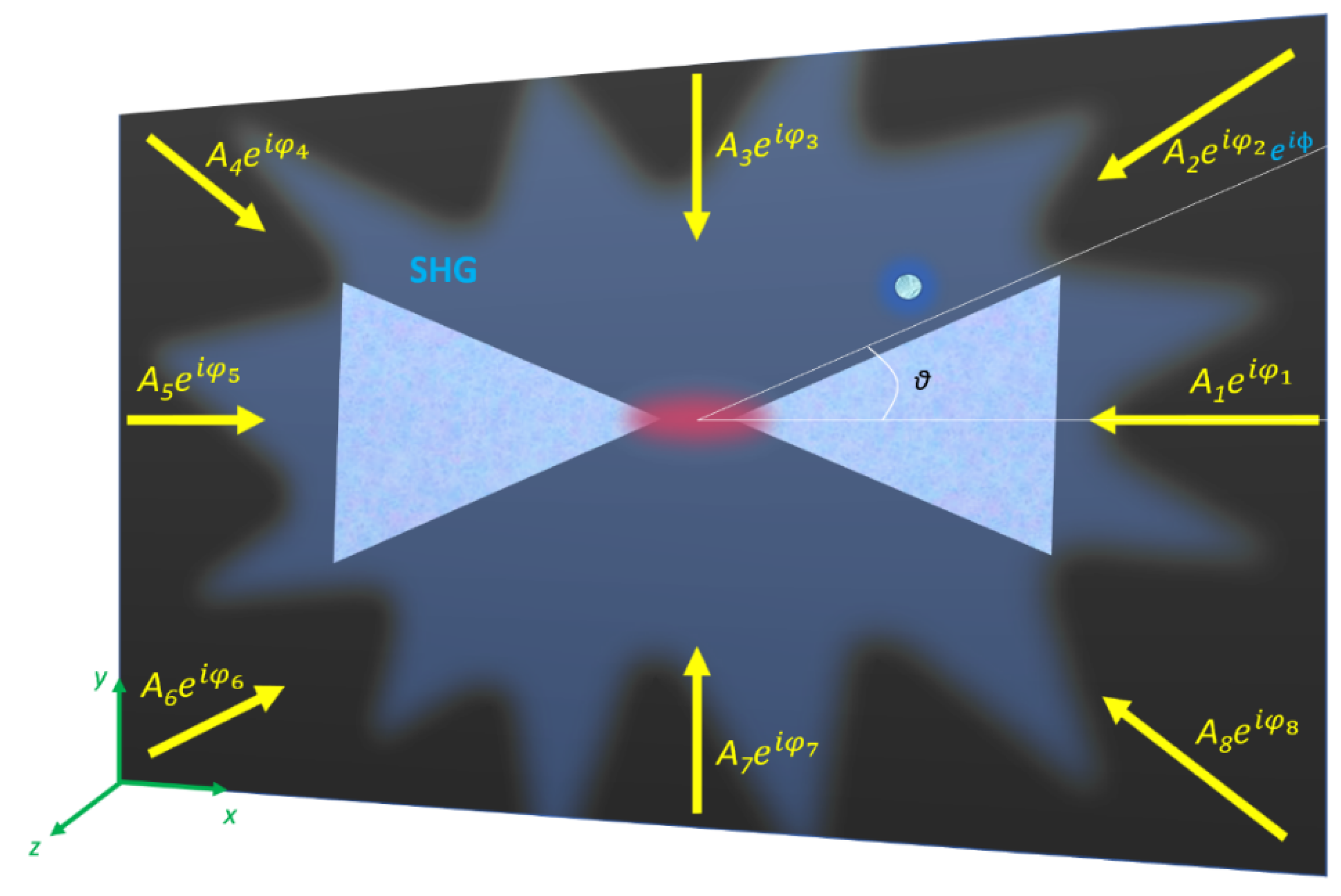
A pictorial view of the considered structure is shown in
Figure 1. The bow-tie antenna has a small nanogap of 10 nm along the
x axis (see
Figure 1). The side of the antenna is fixed to 1045 nm. The pump wavelength is selected to be equal to 1550 nm. For simplicity we analyzed the 2-dimensional case with the
k-vectors in the
xy plane, and, accordingly, the electric field is perpendicular to the latter. It is worth noting this entails coping with a scalar problem.
We synthetize the parameters of the incident plane wave by maximizing the electromagnetic field in the gap region of our antenna. To this aim, we exploit a convex optimization approach for fixed geometry array synthesis, which amounts to dealing with the focusing problem in electromagnetic known scenarios. This means that the geometry and the refractive index of the antenna are known. Under the adopted formulation, considering a given set of
N primary sources (plane waves in this case) impinging on the antenna from several angular directions, and assuming, for each of them, the total field
Ei(r), due to an unitary excitation, is known, the goal of the method is to find the complex excitations coefficients (
Ai, φi) such that a simultaneous excitation of the primary field (thanks to the linearity of the scattering phenomena) gives rise to a field whose square amplitude is focused in the neighborhood of the antenna gap, while keeping bounded elsewhere. Such a problem can be formulated as the following optimization strategy:
where
M(r) is a non-negative arbitrary function (namely a mask function) of the coordinate
r spanning the observation domain [
24]. This problem, which is concerned with the most general case of power pattern synthesis problems, is nonconvex in the unknown excitation coefficients. However, in order to ensure achievement of the global optimal solution (with a great advantage in terms of computational resource saving) it can be recast as a convex problem:
where
r1, … , rM denote the position vector spanning the observation domain, and
m = 1, … M are the number of cells of the computational grid. As a matter of fact, the constraints of Equation (2) are linear in terms of
Re(Aie jφi),
Im(Aie jφi) so that they also define a convex set in the space of the unknowns. Moreover,
Re{E(rgap)} is also a linear function of the unknowns, thus Equation (2) is equivalent to the maximization of a linear function in a convex set [
24]. For more details, the reader is referred to Ref. [
24,
25]. The synthesis procedure is implemented in MATLAB using the subroutine
fmincon devoted to constrained linear problem solutions. Thus, our synthesis procedure gives the complex amplitude of the plane waves that, provided a proper discretization of the source domain (number of antennas), guarantees a maximum of the electromagnetic field in the gap region of the bow-tie. In this respect, it is worth underlining that the minimum non-redundant number of antennas which guarantees the achievement of a global optimal solution is given by 2
ka + 1 [
24], where
k is the wavenumber in the medium hosting the antenna and
a is the radius of the convex envelope enclosing the computational domain. This entails consideration of the inter-distance antenna element approximately equal to
λ/2 on a circle enclosing the computational domain. This notwithstanding, the method can work also with aspect limited configuration and a non-equispaced antenna element [
25]. However, even if a lower number of antennas is used in the array synthesis, the method can still achieve satisfactory results for the SHG problem at hand, but for an unavoidable degradation of the result in terms of field concentration. Finally, the computational time to solve the synthesis problem strictly depends on the discretization of the observation domain (number of constraints). For example, in the scalar 2D case at hand, the computational time takes approximately a few tens of seconds on a standard PC.
The coefficients from the synthesis procedure are shown in
Figure 2, wherein the synthesized amplitude and phase are shown when the number of pump plane waves is equal to 1, 2, 4, 6 and 8, respectively. For the sake of simplicity, we have considered plane waves as the primary source, but the adopted procedure can be exploited with any kind of incident field. In the case of plane waves, this means that the excitation coefficients are related to an array placed in the far field of the bow-tie antenna in such a way the impinging field can be assumed as a plane wave in proximity of the antenna. All the antennas are assumed to be on a common circle of a fixed radius and a common phase reference is assumed. The focusing problem has been solved for
i = 2, 4, 6 and 8. It is worth pointing out that the case of
i = 2 has a small number of degrees of freedom for the optimization problem, so the focusing outcome is expected to not be satisfactory (no field focusing is expected). Nonetheless, for comparison purposes, we have also considered such a case. The mask function
M has been set as a circle with diameter
λ/4, which represents a tradeoff between actual feasibility in the synthesis of a pencil beam pattern and required spot size for the enhancement of the field in the antenna’s gap. The computational domain has been discretized into
MxM cells according to the appropriate sampling rule. Finally, for simplicity, we consider only multiples of π/4 as incident pump angle
θi, in order to keep complexity of the setup as low as possible (
Figure 1).
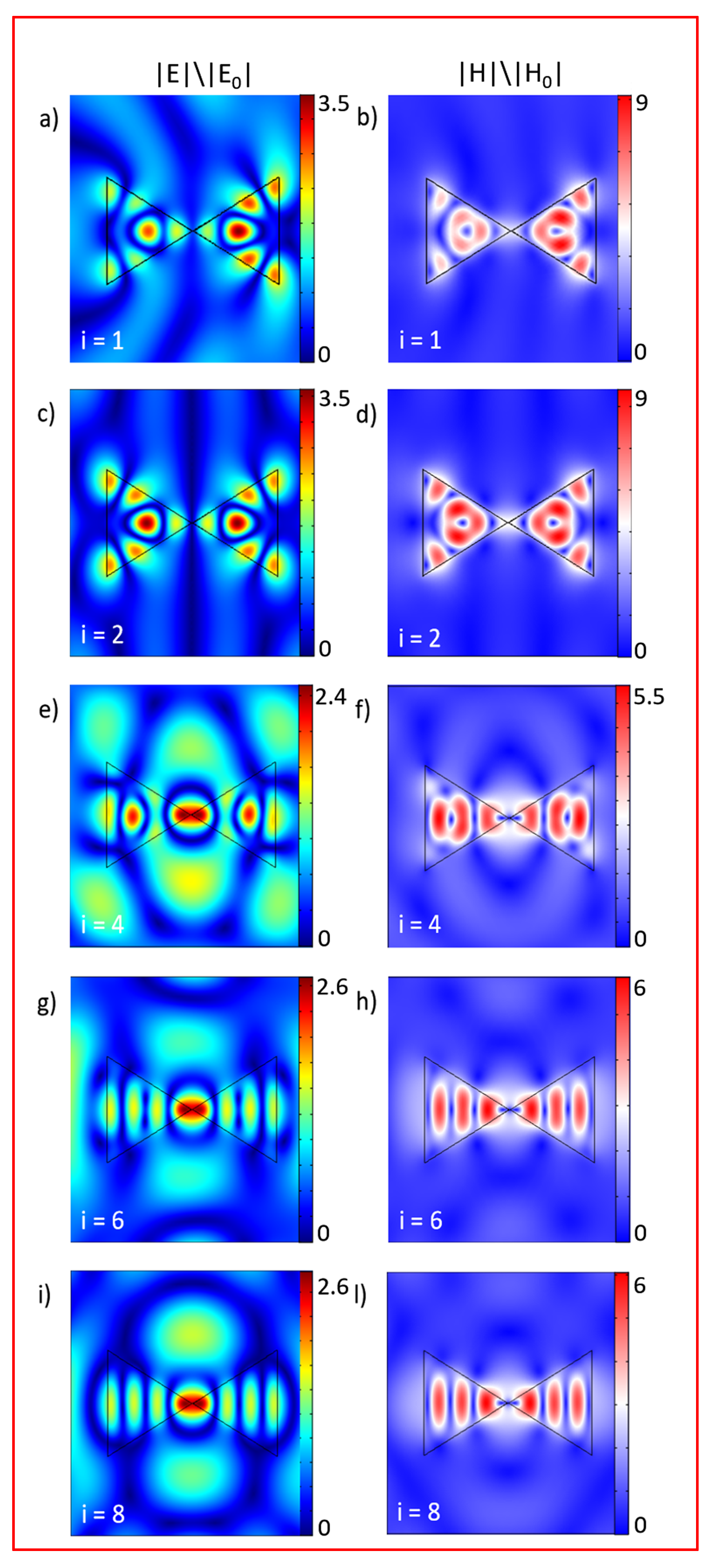
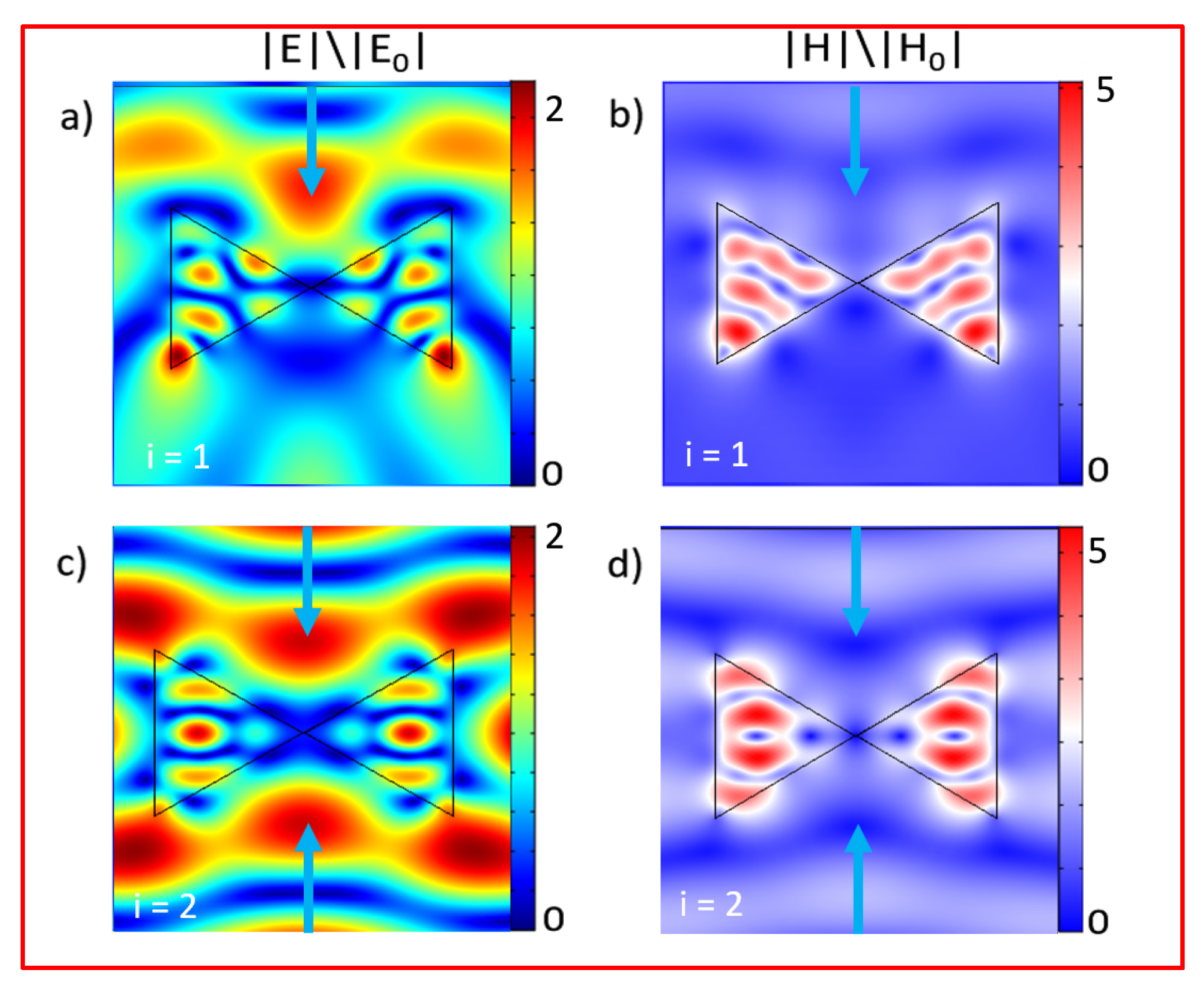
Figure 3 shows the obtained total electric and magnetic field distributions. The field simulations are performed on a finite element method solver implemented in COMSOL Multiphysics® v. 5.2.
Please note that the case of
i = 1 with the plane wave propagating along the
x-axis guarantees a high magnetic field enhancement (more than four times) in the gap region (see
Figure 3), which could be of interest for practical applications. We verify that the case of
i = 1 with a single plane wave excitation propagating along the
y-axis does not fulfill any significant enhancement in the gap region of the antenna. The same consideration holds for the case of
i = 2; see
Figure A1 in the
Appendix for the details. For this reason, in the manuscript when referring to the cases of
i = 1 and 2 we are assuming plane waves propagating along the
x-axis.
Once we have characterized the linear behavior of our antenna, we study the nonlinear problem. Also, the second harmonic process is simulated in COMSOL. In the calculations, we used
χ(2) = 100 pm/V as reported for Al
0.18Ga
0.82As in Ref. [
26]. We thus solved the problem of the generated SH wavelength using the calculated fields at the fundamental wavelength (FW) to define the second harmonic source as external current density. The
i-th component of the external current density
Ji is expressed as:
Ji = jω
SHε
0χ
(2)E
FW,j E
FW,k, where ε
0 is the vacuum permittivity, ω
SH is the angular frequency of the SH signal (i.e., ω
SH =2 ω
FW) and E
FW,i is the
i-th component of the electric field at the FW along the
i-th direction of the crystalline axis of the crystal [
26]. In the adopted 2D approximation, the electric field of the SH has only x and y components. In the simulation we assume a π/4 rotation of the crystalline axis around the
x-axis of the laboratory reference system. The domain is truncated by a perfectly matched layer (PML) and far-field calculations are done on the inner boundary of the PML domain.
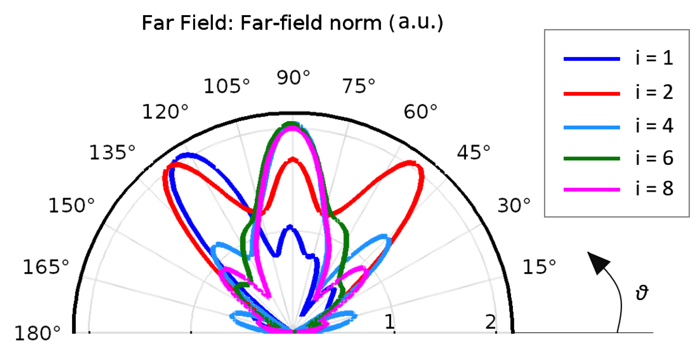
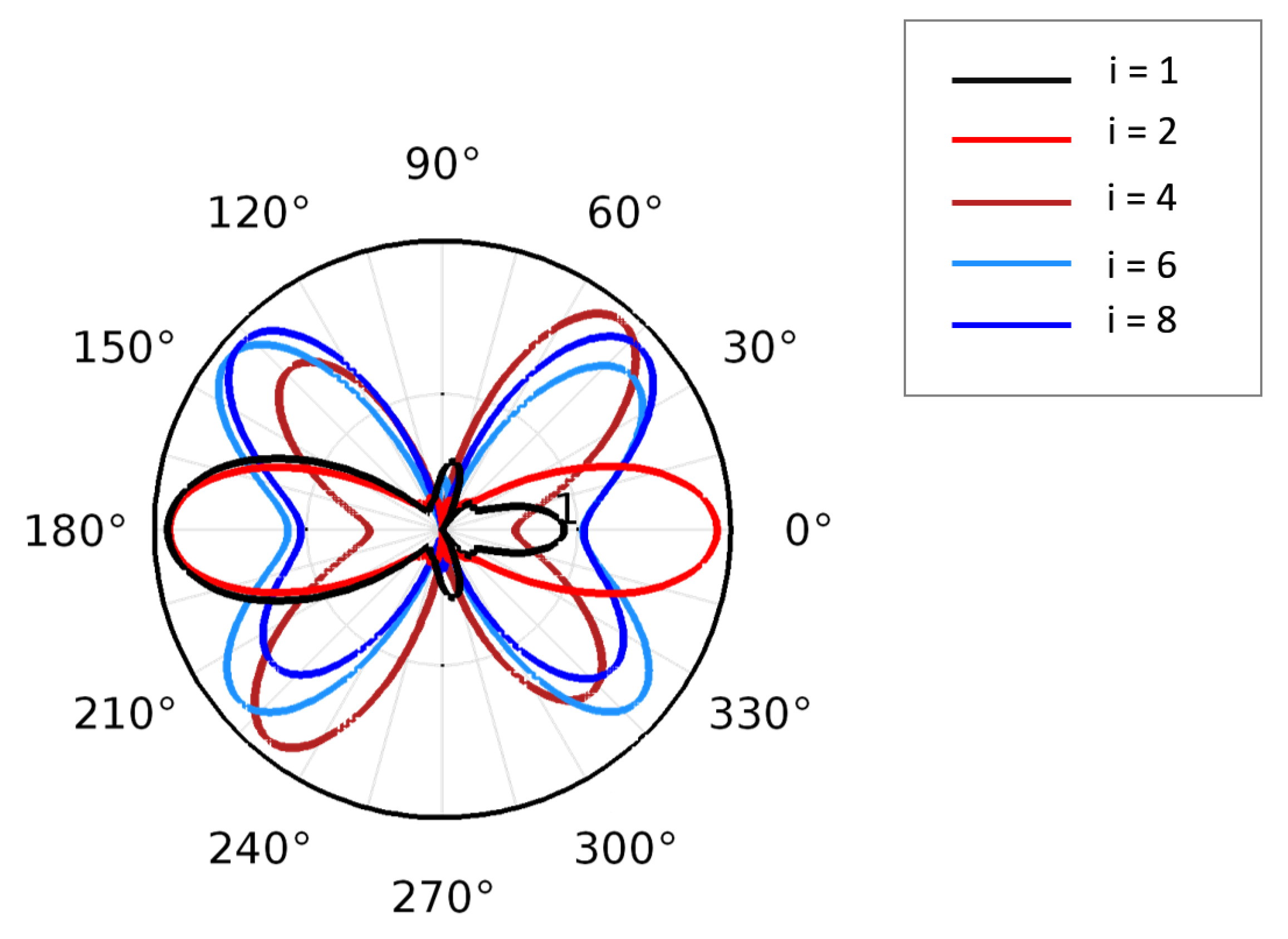
Figure 4 summarizes the obtained results for the different number
i of incident plane waves with the associated optimal parameters as reported in
Figure 2. The radiation pattern indicates that the SH signal presents a symmetry with respect to the
x direction. In fact, for the symmetric field excited at the FW (around the
x-axis) the SH radiation pattern also maintains the same symmetry. For improving the clarity of the obtained results, we plot only the upper part of the radiation pattern (0° ≤
θ ≤ 180°). It is possible to note that when
i = 1, the radiation pattern of the second harmonic signal has major lobes around 125° (and at 235°, i.e., in the lower part) and secondary lobes can also be observed. This behavior in directivity can be explained by the fact that the structure is excited with a single plane wave propagating along the -
x direction. Such an excitation implies that the FW field is more concentrated in the right half of the bow-tie antenna as can be observed in
Figure 3a. Thus, the second harmonic signal, which is proportional to the square of the fundamental field, is also more intense in the same right half of the antenna. We observe that the SH scattered power from the antenna is mostly coming from the right part of the structure with a specific direction which directly translates into the SH pattern of
Figure 4 in the far field. This could represent a drawback in practical applications where it could be beneficial to have the maximum harmonic generation coincide with the laboratory axis frame direction, i.e., at
θ = 90° and 270°, respectively. Moreover, no significant field enhancements are obtained in the gap region. We therefore consider the other possible excitation conditions. For the case of
i = 2, the SH signal has a maximum for
θ = 90° (and 270°); however, two main lobes are observed at 50° and 130° in the upper region and at 310° and 230° in the lower one. These lateral lobes can be reduced by exciting the bow-tie structure with the simultaneous excitation given by four plane waves. Please note that for the case of
i = 4, the field induced in the AlGaAs antenna at the fundamental field is not perfectly symmetric with respect to the
x-axis as shown in
Figure 3e,f. Therefore, this asymmetry translates into an SH radiation diagram that is not perfectly mirrored with respect to the
x-axis. Finally, for the case of
i = 6, major lobes in the SH radiation pattern at 90° and 270° can be obtained. The same considerations about the symmetry for the case of
i = 4 hold also for this instance. Thus, to conclude, a further improvement can be obtained for the case of
i = 8, where the FW mode (see
Figure 3i,l) and SH signal are almost perfectly symmetric (with respect to the
x-axis) and major lobes in the SH radiation pattern are reached exactly at 90° and 270° as depicted in
Figure 4.
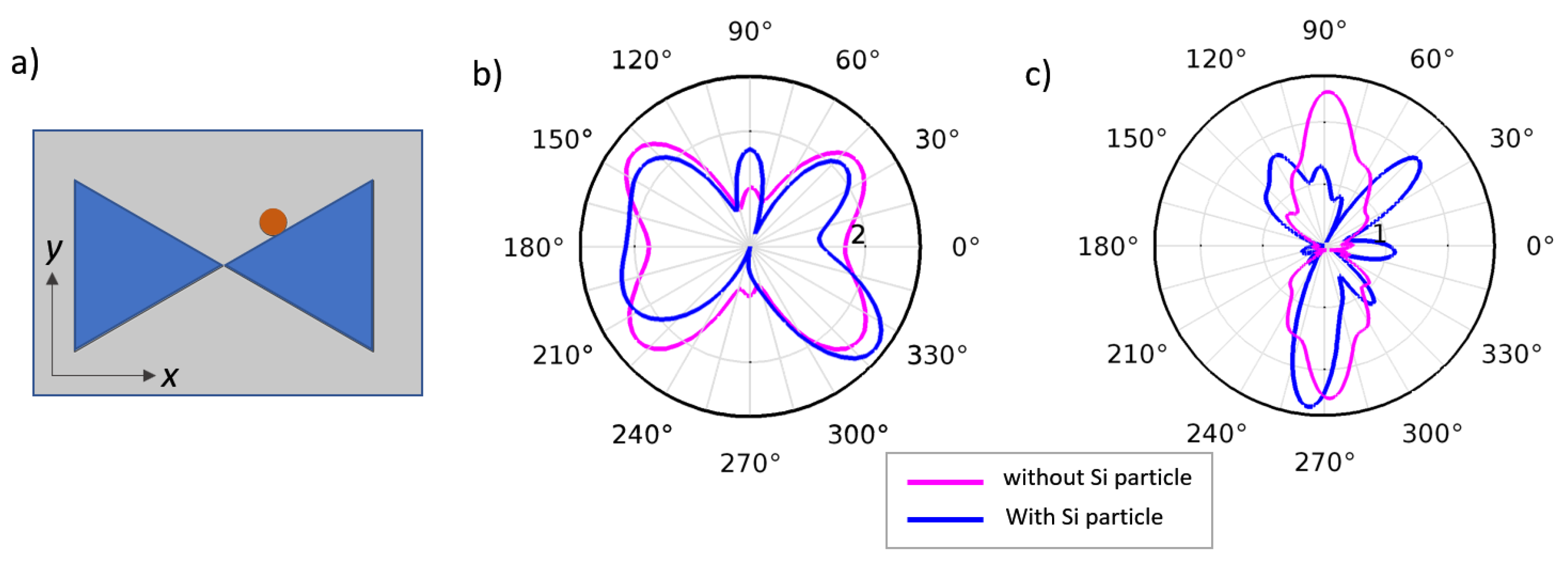
Finally, we study how the presence of a particle can affect the nonlinear radiation behavior. The idea is to sense the presence of a particle in the enclosing media by evaluating the changes in the far field signal at the harmonic frequency. For simplicity, we consider the instance of
i = 6, which is the case for which the minimum number of plane waves guarantees a directive SH radiation pattern. We model a generic perturbation as an extra phase term
ϕ on one incident plane wave (see
Figure 1) and we evaluate changes in the SH far field due the introduction of the extra phase term. An obstacle causes a change in the scattered field, and this can be modelled at first order as a modulation of the phase and amplitude of the incident plane waves. To make the discussion as simple as possible, yet capturing the main idea we want to exploit here, we model the perturbing object as an extra phase term in only one of the incident plane waves (see caption of
Figure 1). This model is exact only when the perturbing object is a slab that ensures high transmission with a fixed phase delay. To provide a more realistic scenario, in the
Appendix, we also describe the case where the perturbation is due to the presence of a small dielectric particle. Let us define a figure of merit (FOM) as the ratio between the far field at
θ = π/2 in the absence of the simple perturbation (i.e., when
ϕ = 0) with respect to the far field in the presence of the perturbation (i.e.,
ϕ ≠ 0).
Figure 5 summarizes the obtained results. FOM values of the bow-tie nanoantenna-based platform in the nonlinear regime are significantly higher than those featured in the linear regime in the range 0 <
ϕ < 3/2π. As can be seen in
Figure 5b,c, the far field of the SH signal is dramatically modified when
ϕ = π while no significant variations are detected for the FW radiation pattern. Although this is a preliminary analysis of this phenomenon, the advantage of using the SH radiation pattern for sensing applications is clear. However, by further engineering the nanoantenna geometries to attain higher nonlinearities, SH bow-tie sensing platforms have the potential to overcome standard linear platform performances.


