Article

Beyond Snap-In: A Hybrid Nonlinear Control Approach for Actuators Possessing a Square-Law Characteristic

1
Department of Automation & Measurement, Ocean University of China, Qingdao 266100, China
2
Department of Computer Science & Software Engineering, Auburn University, Auburn, AL 36849, USA
3
Department of Electrical & Computer Engineering, Auburn University, Auburn, AL 36849, USA
4
Department of Ocean Engineering, Zhejiang University, Zhoushan 316000, China
*
Author to whom correspondence should be addressed.
These authors contributed equally to this work.
Current address: 238 Songling Road, Qingdao City 266100, Shandong Province, China.
Electronics 2019, 8(8), 863; https://doi.org/10.3390/electronics8080863
Submission received: 29 June 2019 / Revised: 30 July 2019 / Accepted: 31 July 2019 / Published: 3 August 2019
(This article belongs to the Section Systems & Control Engineering)

Abstract

:
The undesired square-law characteristics in micro-electrostatic actuators and magnetic solenoids results in a limited stable range, which reduces their application fields and performance. This research investigated the isomorphic dynamics in these actuators and observed that the nonlinear drive force and the uncertain time delay are the challenges for the full range position controller design. A hybrid nonlinear control scheme includes an input–output linearization controller and a feedback posicast compensator for targeting these problems with abundant stability margin. The experimental results show that the stable range has been extended from 33% to 80%. Furthermore, it is the first literature report of this type of actuator that can track sinusoidal motion beyond the conventional stable range with an amplitude of 70% of the total range. This contribution can significantly enhance the performance of micro-sensors or expand the usage of electrostatic/magnetic actuators in motion-control systems.

1. Introduction

Electrostatic parallel-plate actuators (PPA) and magnetic solenoids are commonly used actuators in industrial applications. PPAs are used to generate desired motion in micro-electro-mechanical systems (MEMS) devices such as antennas [1], resonators [2], accelerometers [3], switches [4], micro-mirrors [5], and gyroscopes [6]. The nonlinear plunger-type solenoids are also used as key actuators in variety of fields, such as biomedical apparatuses [7], internet of things [8] and magnetic bearings [9].
These kinds of actuators may have different exteriors, but their physical dynamics are isomorphic in that the mechanical part is a linear second-order system and the driving force is proportional to the square of the input term [10,11]. Consequently, they share a common fatal defect that the inherent nonlinear driving forces produce a limited open-loop stable range to avoid the famous snap-in problem. Figure 1 illustrates this snap-in phenomenon. PPAs/solenoids operate by generating a displacement in response to an applied voltage/current. They have an electrically controlled stable displacement range, x, of 0 x < x 0 / 3 , where x 0 is the total traveling distance. An open-loop command attempting to further increase displacement results in unstable motion with the actuator snapping into the full range.
Thus, most applications use the solenoids/PPAs as switches or operating the actuator around an operating point with a small amplitude of motion, which can ignore this undesired characteristic. Extending the stable operating range in a practical way is highly expected to enhance the performance for many industrial products. By breaking the barrier of this snap-in trap, MEMS gyroscopes can greatly enhance their relatively low signal-to-noise ratio [12]; the scanning range of micro-mirrors would be enlarged to benefit autonomous cars [13]; solenoids could be used as a low-cost solution for motion-control systems to replace small motors [14].
Several feedback control solutions have been investigated to increase the stable displacement range using various controller architectures. Examples include the series capacitor method [15], synthetic voltage division [16], various electrode configurations [17], charge control [18], negative capacitance control [19], dual actuator configuration [20] and fractional order controller [21]. An alternative approach would be modifying the dynamics by using advanced mechanical design [22,23].
The contributions of this work are summarized as follows: (1) The comprehensive mechanical and electrical coupling model for actuators with square-law input characteristics are analyzed and unified. This model points out the challenges for the control system design. (2) A hybrid nonlinear control policy is designed for the position control purpose with sufficient stability robustness. This control scheme can effectively cancel the nonlinear term and track the reference position. (3) The effectiveness of the proposed method is experimentally verified that rapid response and 2.5x extended stable range are demonstrated. In particular, the AC motion beyond the snap-in limit with an amplitude of 70% of the total traveling range is the firstly reported for the actuators with this nonlinear square characteristic.
The remainder of the paper presents the details.

2. Kinematics of Actuators Possessing a Square Characteristic

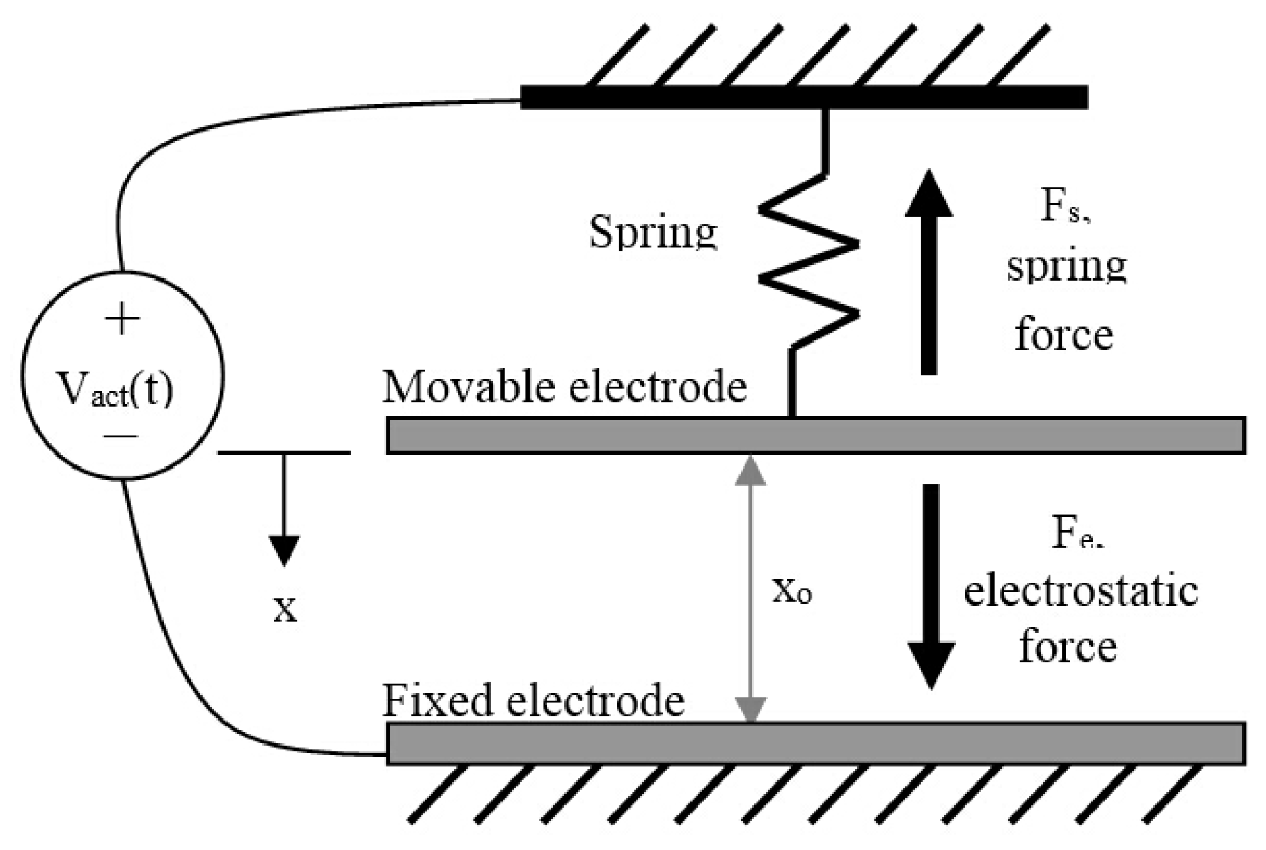
2.1. Kinematics of PPAs

An illustrative drawing of a PPA is presented in Figure 2. The planar electrodes are arranged in a parallel configuration with an overlapping surface area, A, and a rest distance between them of x 0 . The bottom electrode is fixed in space and the top electrode can move toward or away from the bottom electrode. The system’s suspension system constrains the motion of the top electrode and is modeled by the system spring constant, k. C a c t is the capacitance between the two electrodes and is modeled by
C a c t = ε 0 ε r A x 0 x ( t ) ;
when the displacement x ( t ) is zero, the capacitance reaches a minimum value C m :
C m = ε 0 ε r A x 0
where x is the motion of the top electrode, ε 0 is the permittivity of free space and ε r is the relative permittivity of the gas in between the electrodes. If a voltage, V a c t , is applied across the two electrodes, an electrostatic force,
F e ( x , V a c t ) = ε 0 ε r A V a c t 2 ( t ) 2 ( x 0 x ( t ) ) 2 ,
results that pulls the top electrode closer to the bottom electrode until its motion is balanced by the spring force
F s = k x ( t )
from the suspension system. In this simplified PPA model, the suspension system is assumed to be satisfactorily modeled by a linear spring. Additionally, capacitive fringing field effects have been ignored. This is a reasonable assumption as long as the electrode overlap area is much greater than the electrode separation distance squared [24]. Using (3), a nonlinear differential equation that models the PPA system dynamics can be developed:
m x ¨ ( t ) = c x ˙ ( t ) k x ( t ) + ε 0 ε r A V a c t 2 ( t ) 2 ( x 0 x ( t ) ) 2 .
Here, m is the proof mass, typically the movable electrode, and c is the system coefficient of damping. The system’s natural frequency, ω 0 , is:
ω 0 = k m ,
while Q, the mechanical quality factor, is
Q = ω 0 m c .
MEMS devices are generally designed to be highly underdamped [24], except for MEMS accelerometers, which are usually designed to be critically damped [25].
When the PPA is operated in its open-loop stable range of motion, the electrostatic force and the spring force are in equilibrium. However, since the spring force is linearly proportional to displacement and the electrostatic force is a nonlinear function of both displacement and applied voltage, the actuator has a limited open-loop stable range of displacement of 0 x < x 0 / 3 . If the applied voltage is further increased in attempt to reach a displacement of x 0 / 3 or further, the system will no longer be in equilibrium since the electrostatic force will always be greater than the spring force. This results in the movable electrode accelerating toward and snapping into contact with the fixed electrode. This event is called snap-in. The minimum applied voltage that will cause snap-in is referred to as the pull-in voltage [25], V p i , where
V p i = 8 ( x 0 ) 3 27 ε 0 ε r A .

2.2. Kinematics of Solenoids

A typical configuration of a solenoid in a spring-mass-damper system is illustrated in Figure 3. Its mathematical description is:
m x ¨ ( t ) + c x ˙ ( t ) + k x ( t ) = μ 0 μ r N 2 A I 2 ( t ) 2 ( d + x 0 x ( t ) ) 2 ,
where x is the displacement of the armature, μ 0 is the permeability of free space, A is the cross-sectional area of the core, N is the number of the turns of the coil, μ r is the relative permeability of the dielectric material between the coil and the armature, x o is the initial air gap between the armature and the back side of the frame and d is the additional initial air gap related to the solenoid’s geometry, which is much smaller than x 0 in general. Also, m is the proof mass of the armature, k is the stiffness of the spring and c is the system damping coefficient. I ( t ) is the current through the coil [26,27]. L ( x ) is the inductance of the coil that depends on the air gap x [26,27], which is:
L ( x ) = μ 0 μ r A d + x 0 x ( t ) .
The plunger is driven by a magnetic force which can be described by:
F ( x , I ( t ) ) = μ 0 μ r N 2 A I 2 ( t ) 2 ( d + x 0 x ( t ) ) 2 .
At equilibrium:
k x = μ 0 μ r N 2 A I 2 ( t ) 2 ( d + x 0 x ( t ) ) 2 .
Because the magnetic force is also nonlinear, this type of actuator also has the pull-in effect. The pull-in current is:
I p i = 8 ( x 0 ) 3 27 μ 0 μ r N 2 A .
The definitions for quality factor and resonant frequency are as same as (6) and (7).

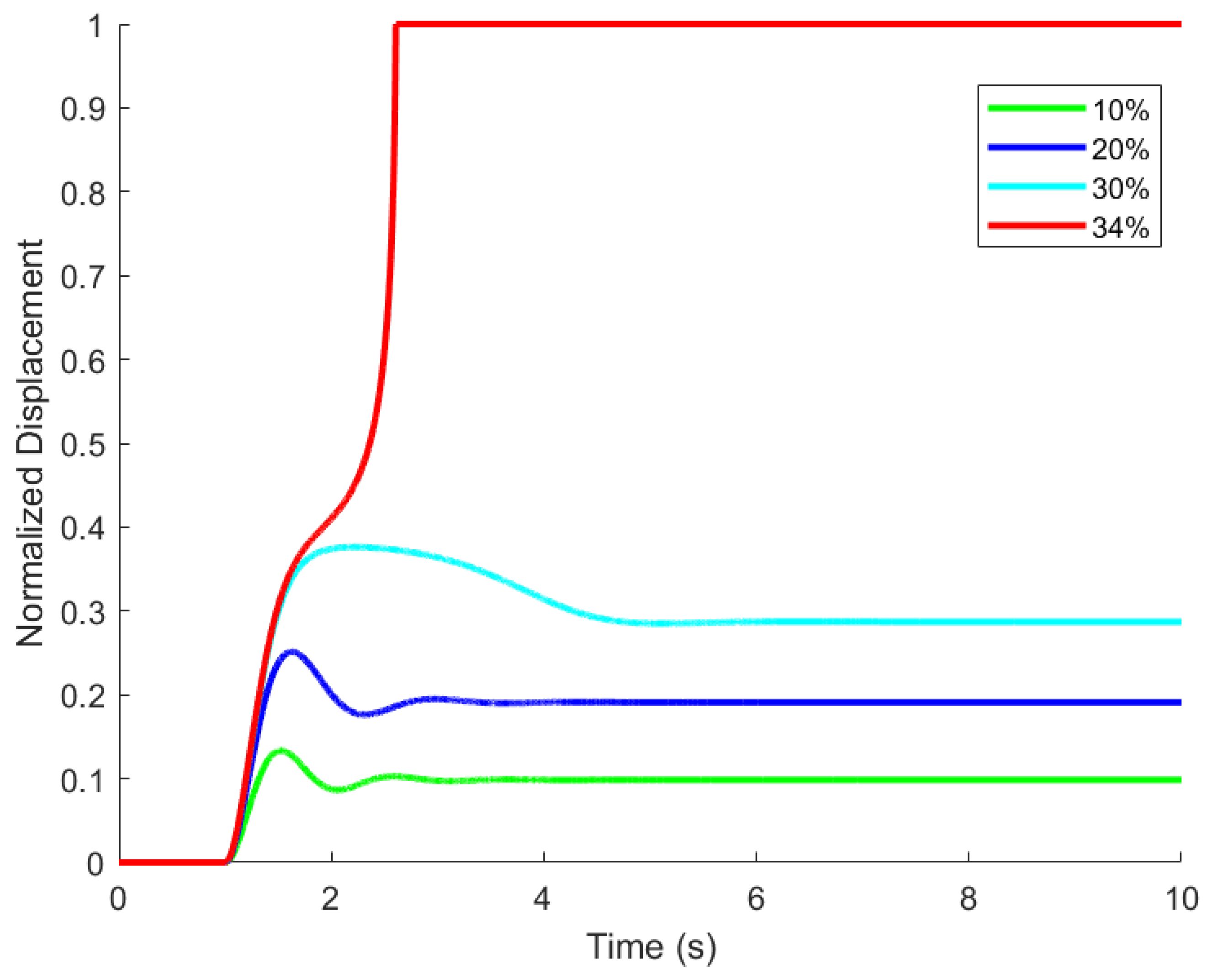
2.3. The Pull-in Effect and Stable Range of PPAs

The stable traveling range of PPAs is less than 1/3 x 0 . A linear approximation by (5) can be formed by Taylor series expansion of F e ( x , V ) [28]. From the Taylor series:
F e ( x , V ) x = ε 0 ε r A V 2 ( t ) ( x 0 x ( t ) ) 3 ,
Let x a be a desired displacement over the stable range and V a be the voltage from (3). Then:
F e ( x , V ) = ε 0 ε r A V a 2 2 ( x 0 x a ) 2 ( x ( t ) x a ) 0 + ε 0 ε r A V a 2 ( x 0 x a ) 3 ( x ( t ) x a ) 1 ,
Define N and K E L as:
N = ε 0 ε r A V a 2 2 ( x 0 x a ) 2 x a ε 0 ε r A V a 2 ( x 0 x a ) 3 K E L = ε 0 ε r A V a 2 ( x 0 x a ) 3 .
Then substituting (16) for F e ( x , V ) in (5) yields the linear approximation:
m x ¨ ( t ) + c x ˙ ( t ) + ( k K E L ) x ( t ) = N .
The characteristic equation has roots at:
s 1 , 2 = 1 2 ( c m ± ( c m ) 2 4 ( k K E L m ) ) .
This system is only stable by open-loop voltage control for 0 x < x 0 / 3 . If the PPA voltage is increased in attempt to increase the displacement to or beyond x 0 / 3 , the two electrodes will snap into contact.

2.4. The Pull-In Effect and Stable Range of Solenoids

Because solenoids have the same type of driven force, the PPAs’ pull-in principle can also be applied to solenoids and generate the same result. The stable traveling range of solenoids is also up to 1/3 of x 0 . A linear approximation around an operational point of the solenoid can be formed by Taylor series expansion of F m ( x , I ) . From the Taylor series:
F m ( x , I ) x = μ 0 μ r N 2 A I 2 ( t ) ( d + x 0 x ( t ) ) 3 ,
Let x a be a desired displacement over the stable range and I a be the current from (9). Then:
F m ( x , I ) = μ 0 μ r N 2 A I a 2 2 ( d + x 0 x a ) 2 ( x ( t ) x a ) 0 + μ 0 μ r N 2 A I a 2 ( d + x 0 x a ) 3 ( x ( t ) x a ) 1 ,
Define N and K M as:
N = μ 0 μ r N 2 A I a 2 2 ( d + x 0 x a ) 2 x a μ 0 μ r N 2 A I a 2 ( d + x 0 x a ) 3 K M = μ 0 μ r N 2 A I a 2 ( d + x 0 x a ) 3 .
Similiar to PPAs, solenoid’s snap-in problem is also able to be characterized by (17) and (18). This system is only stable by open-loop current control for 0 x < x 0 / 3 . If the current is increased in attempt to increase the displacement to or beyond x 0 / 3 , the armature will contact the bottom of the frame.

3. Characteristics of Square-Law Actuator Systems in Circuits

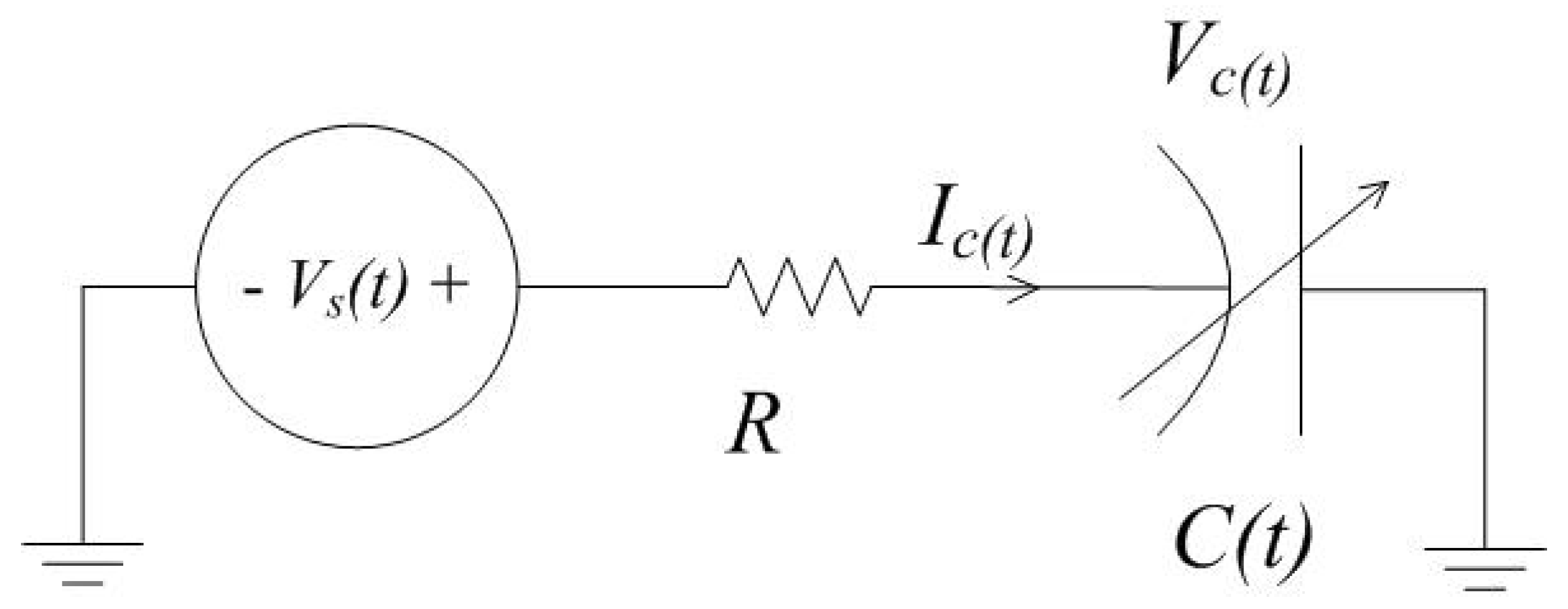
3.1. PPAs with a Series Resistor

PPAs contain variable capacitance which depends on the displacement of the movable electrode. Consider a time-variant capacitor with a series resistor, R, which is used to protect the capacitive element and prevent the power source from shorting to ground in case the MEMS device’s electrodes physically contact each other. The circuit’s schematic is given in Figure 4. In addition, different configurations can be transformed into this model using the Thevenin equivalent circuit method.
The circuit’s behavior is described by:
I c ( t ) = ( V s ( t ) V c ( t ) ) / R = V ˙ c ( t ) C ( t ) + V c ( t ) C ˙ ( t ) ,
where V s is the power source, V c is the voltage across the variable capacitor and I c is the current through it. Though (22) fully characterizes the circuit’s behavior, it is difficult to solve this nonlinear differential equation in practice and obtain a closed form solution.

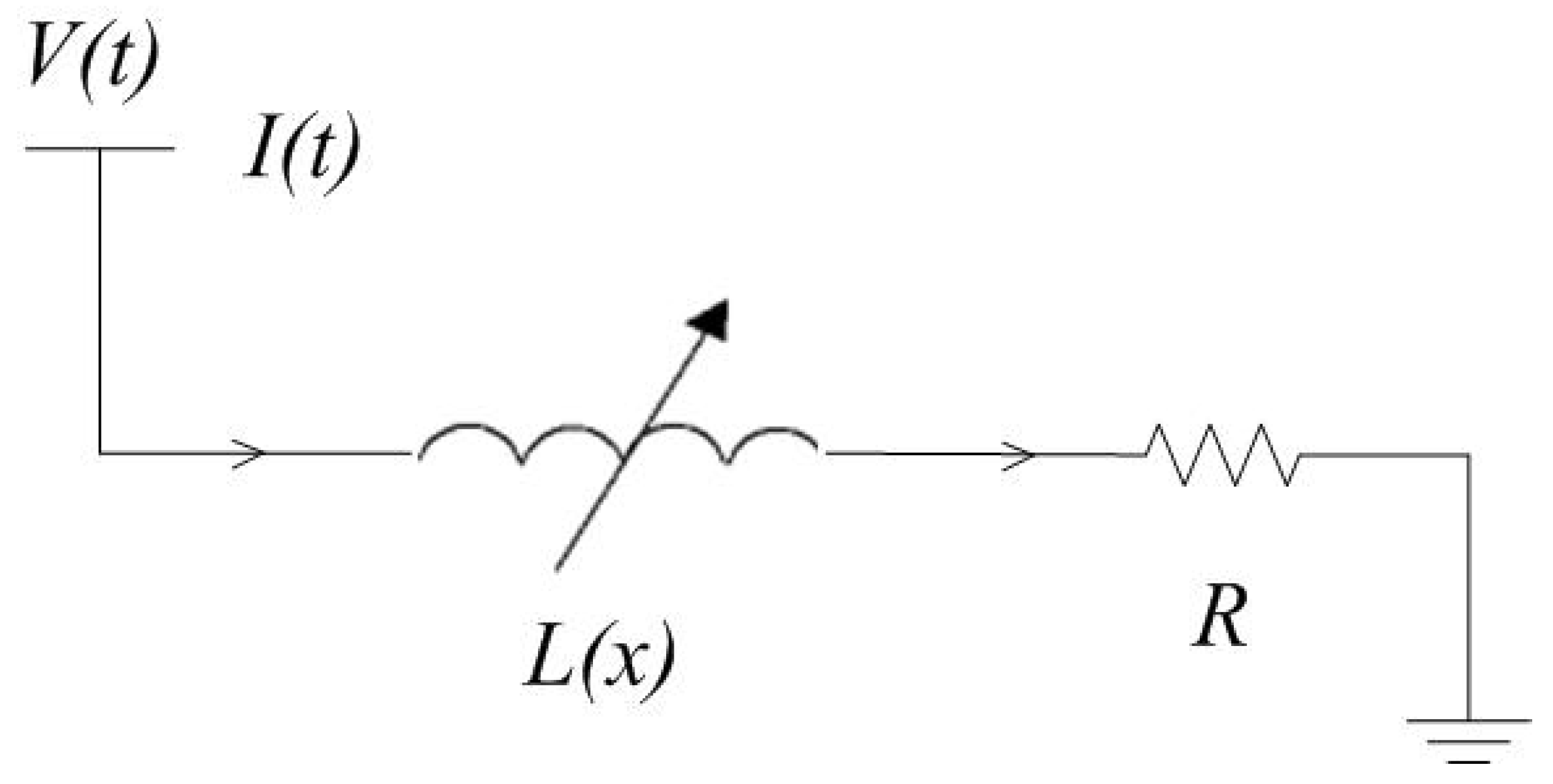
3.2. Solenoids with a Series Resistor

A solenoid can be treated as variable inductor when it is in an electronics circuit. Based on (10), L ( x ) is a variable inductor; the dynamics of the circuit in Figure 5 are modeled as:
L ( x ) d I ( t ) d t + d L ( x ) d t I ( t ) + I ( t ) R = V ( t ) .
According to (9), the electrical and mechanical dynamics are coupled with each other, which makes solving (23) and identifying the time delay between the control voltage V ( t ) and I ( t ) difficult.

4. Control Scheme

4.1. Dynamic System Formulation

By analyzing the mechanical and electrical behaviors of solenoids and PPAs, the general properties of the actuators possessing a square-law characteristic can be summarized as:
(1) The mechanical part is suspended with spring and dampers which can be considered to be a linear second-order system. It is notable that the mechanical suspension is required to work in the linear region to cooperate with this assumption.
(2) The driving force is proportional to the square of the input term and the inverse of the traveling range.
(3) There is always an uncertain time delay between the control voltage and the actual driving force.
Thus, a unified model can be established for the control system design:
m x ¨ ( t ) + c x ˙ ( t ) + k x ( t ) = γ u 2 ( t τ ) ( x 0 x ( t ) ) 2 ,
where γ is the constant coefficient related to the physical structure of the actuator.

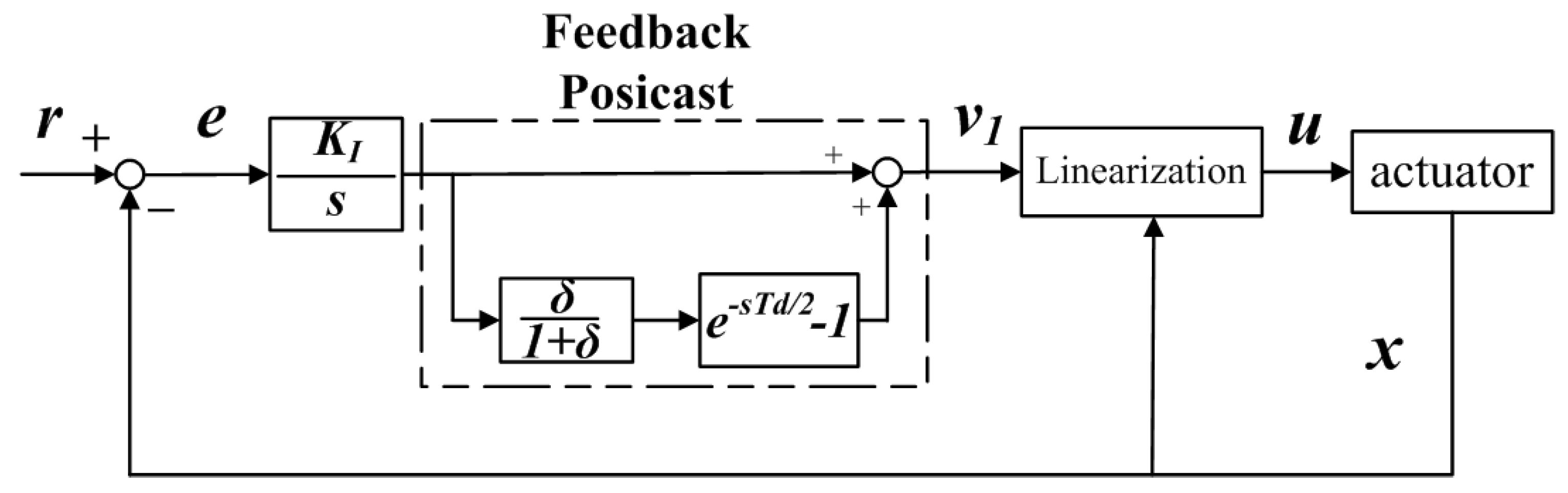
4.2. Hybrid Nonlinear Control Scheme

To overcome the drawbacks of the nonlinear driving force, an input–output linearization (IOL) control policy is first introduced as
u ( t ) = v 1 ( t ) k c ( x 0 x ( t ) )
to cancel the nonlinear terms to prevent the snap-in phenomena, where k c is a positive gain. where v 1 is the new control input and v 1 > 0 . In this situation, the system dynamics become:
m x ¨ ( t ) = c x ˙ ( t ) k x ( t ) + k c γ ( x 0 x ( t τ ) ) 2 v 1 ( t ) ( x 0 x ( t ) ) 2 .
To evaluate the effect of this modified dynamic system with the uncertain time delay, τ , the Taylor series-based approximation can be applied:
x ( t τ ) x ( t ) τ x ˙ ( t ) .
Combining the approximation (27) and (26) will become:
m x ¨ ( t ) = c x ˙ ( t ) k x ( t ) + k c γ v 1 ( t ) + 2 k c γ τ x 0 x ( t ) x ˙ ( t ) v 1 ( t ) + k c γ τ ( x 0 x ( t ) ) 2 x ˙ 2 ( t ) v 1 ( t ) ,
where the last two terms are resulting negative nonlinear damping effects to the system. So, the actual system can be described as:
m x ¨ ( t ) = ( c Δ c ) x ˙ ( t ) ( k Δ k ) x ( t ) + k c γ v 1 ( t ) ,
where Δ c and Δ k are the time-variant perturbations damping coefficient and spring stiffness. Specifically, Δ c is generated from the last two nonlinear damping terms in (28) and Δ k is conducted by the spring softening effect.
As a result, the consequences of introducing this policy into (24) without compensating the time delay effect are degrading the stability margins of the original system. It would be common sense to use a proportional–integral–derivative (PID)-type controller for the non-ideality. However, compensating these nonlinear effects by using a PID controller is challenging.
Therefore, an advanced and robust compensation control policy should be developed to make the basic nonlinear IOL solution practical. This study proposes a feedback posicast and IOL (FPIOL) hybrid scheme to solve this problem, as shown in Figure 6. The inner loop is still the IOL and the outer one is called a feedback posicast compensator whose time domain representation is:
v 1 ( t ) = δ 1 + δ ( v 2 ( t T d 2 ) 1 ) ,
where v 2 is the input of this compensator. The role of the feedback posicast controller is cancelling the undesired oscillation that was introduced by the inner loop [29,30]. The parameters in (30) are illustrated in Figure 7 when the system is stimulated with a step input, where δ is the ratio of the overshoot and T d is the period of the oscillation. It is noted that the term δ is inherently associated with the damping coefficient c.
The ultimate goal is developing an accurate and robust position control system. Thus, there is an integral block ahead of the posicast controller to eliminate the position tracking error. Defining e ( t ) as the position error and the resulting control policy is:
v 1 ( t ) = k I δ 1 + δ ( e ( t T d 2 ) 1 ) d t u ( t ) = v 1 ( t ) k c ( x 0 x ( t ) ) , .
where k I is the integral gain for the position tracking performance.

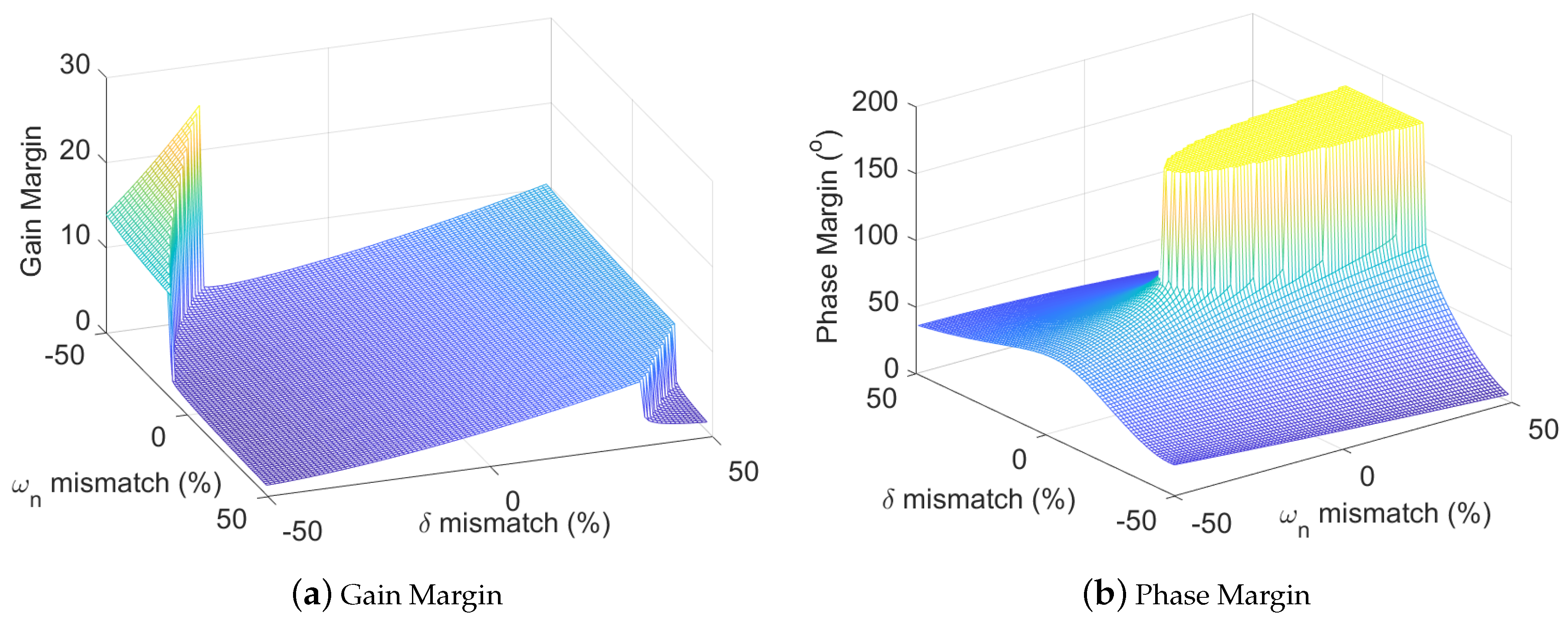
4.3. Stability Analysis

The control policy (31) claims that it is robust, insensitive to model variations, and able to stabilize the overall feedback system. To prove this claimed policy, a nominal model based on the transfer function formulation for the system (29) is established as:
G ( s ) = k c γ m s 2 + c s + k ,
and the outer loop controller is
C ( s ) = 1 s δ 1 + δ ( e s T d 2 1 ) .
Therefore, the tolerance of the nonlinear model mismatch and the uncertain time delay effect can be evaluated by the stability margins of the combined system C ( s ) G ( s ) . These non-idealities are weighted by the mismatch of the overshoot/damping, δ , and the frequency, ω . The visualized numerical results are given in Figure 8.
In terms of the gain margin, it remains stable within the ±50% mismatch of the overshoot and frequency. The positive mismatch of δ in the controller can yield a larger gain margin. The inspiration would be in setting a larger δ when the overshoot in the experiments is hard to be characterized.
The performance of the phase margin in the proposed solution exceeds expectation. When the δ mismatch is within ±20% and ω mismatch is between 30 % and 50 % , the phase margin would be beyond 170 , which is particularly useful to this system with uncertain time delay effect. This unique advantage also solves a common issue for MEMS control systems that their absolute time delay tolerance is low. For instance, a feedback control approach failed due to the insufficient phase margin [31]. Thus, the proposed scheme is an appropriate candidate for both macro and micro actuators from multiple points of considerations.
Though the proposed solution shows good stability robustness, it is notable that the selection of the parameter δ and T d should not be free. It is suggested that the value of T d should be within ± 20 % of the nominal value to conduct a good stability property. Similar to T d , the range of δ should be between 30 % and 30 % to reach the maximum stability margin. Otherwise, an aggressive controller design may lead the system to be unstable due to insufficient stability margins.

5. Experimental Validation

A commercial magnetic solenoid-based evaluation platform was designed to validate the proposed solution. The components of the solenoid are shown in Figure 9a and its equivalent initial gap distance was configured as 5 mm. The platform was mounted on a vibration test system to do the system identification and measurement, which is shown in Figure 9b. The relative displacement between the armature and fixture, x, was measured by two laser vibrometers. The core control algorithm was implemented with a STM32F107 micro-controller and the output data was displayed and recorded through a computer.
A group of step responses were first collected with “different control systems”, as that illustrated in Figure 10. The open-loop system was slightly under damped, but its maximum stable was 1.5 mm, which range in this case was even less than 1/3 of x 0 due to the non-ideal factors in the real setup. The solenoid with the IOL can improve the stable range up to 2.3 mm with a penalty of additional oscillations that verifies the theoretical analysis. The legends of the input were marked with numbers because they did not have any position control functions. The further command led the system to snap-in because of the insufficient phase margin. To overcome these issues, a PID controller was developed along with the IOL and further extended the stable range to 4 mm. However, the oscillation was still not severe, especially if the desired position was around 3 mm, because of the residual nonlinear terms.
Based on the results with the IOL, the parameter T d and δ were characterized to conduct a FPIOL as proposed in Figure 6. The adjustment of the integral gain increased gradually to optimize the stability and performance. The final results are shown in Figure 10d. It successfully significantly cancelled the oscillation without sacrificing the stable traveling range, which was 80% of the total gap.
The vibration system characterized the frequency responses of the solenoid with different control systems to further demonstrate the advantage of the proposed hybrid nonlinear controller FPIOL, which is shown in Figure 11. The original system had a resonant frequency with a quality factor of 2.4, while the IOL increased it to 3.3, which means the damping ratio was lower. Both the amplitude and phase plot of the FPIOL demonstrated the advantages: the damping ratio was reduced below 2, the bandwidth was withheld, and the phase margin was enhanced by 45 . The frequency domain characterization well matched to the theory sponsored the time domain results.
Another significant contribution is that the FPIOL enabled the AC-type motion beyond the snap-in point with a large magnitude, as shown in Figure 12. The motion was performing a sinusoidal trace beyond the 1/3 range with an amplitude of 3.5 mm and a frequency of 1 Hz. In comparison, a conventional actuator with this square-law characteristic can only do AC motion below the snap-in range and the amplitude is only 1/10 of the total displacement. The outputs of the posicast controller and the actual current are also displayed in Figure 12.

6. Conclusions

The mechanical and electrical dynamics of the actuator possessing a square-law characteristic were analyzed from the prospective of control systems. A hybrid nonlinear control policy that contains a nonlinear control law, input–output linearization, and a feedback posicast compensator was designed and its stability was analyzed. The experimental results verified that the proposed solution can effectively regulate the actuator’s set point or track an AC motion with high performance. This control technique can contribute to industrial motion-control systems or MEMS inertial sensors.

Author Contributions

Conceptualization, R.N.D.; Data curation, X.W., R.H. and Y.D.; Formal analysis, C.L.; Funding acquisition, L.Z.; Investigation, R.H., L.Z. and D.S.; Methodology, C.L., X.W. and L.Z.; Project administration, D.S.; Software, X.W.; Validation, C.L.; Visualization, Y.D.; Writing—original draft, C.L.; Writing—review & editing, X.W., R.H. and R.N.D.

Funding

This research was funded by Fundamental Research Funds for the Central Universities under Grant 201964012, National Natural Science Foundation of China under grant number 41527901 and Shandong Province Natural Science Foundation, China, under grant number ZR2017MEE015.

Conflicts of Interest

The authors declare no conflict of interest.

Abbreviations

The following abbreviations are used in this manuscript:
PPAParallel-Plate Actuator
MEMSMicro-Electro-Mechanical Systems
IOLInput–Output Linearization
FPIOLFeedback Posicast Input–Output Linearization
PIDProportional–Integral–Derivative

References

  1. Sundaram, A.; Maddela, M.; Ramadoss, R.; Feldner, L.M. MEMS-based electronically steerable antenna array fabricated using PCB technology. J. Microelectromech. Syst. 2008, 17, 356–362. [Google Scholar] [CrossRef]
  2. Langfelder, G.; Caspani, A.; Tocchio, A. Design criteria of low-power oscillators for consumer-grade MEMS resonant sensors. IEEE Trans. Ind. Electron. 2013, 61, 567–574. [Google Scholar] [CrossRef]
  3. Yan, S.; Xie, Y.; Zhang, M.; Deng, Z.; Tu, L. A subnano-g electrostatic force-rebalanced flexure accelerometer for gravity gradient instruments. Sensors 2017, 17, 2669. [Google Scholar] [CrossRef] [PubMed]
  4. Peng, Y.; Sun, Y.; Luo, G.; Wu, G.; Zhang, T. Recent Advancements in Inertial Micro-Switches. Electronics 2019, 8, 648. [Google Scholar] [CrossRef]
  5. Zhang, J.; Zhang, Z.; Lee, Y.; Bright, V.M.; Neff, J. Design and investigation of multi-level digitally positioned micromirror for open-loop controlled applications. Sens. Actuators A Phys. 2003, 103, 271–283. [Google Scholar] [CrossRef]
  6. Giner, J.; Maeda, D.; Ono, K.; Shkel, A.M.; Sekiguchi, T. MEMS Gyroscope With Concentrated Springs Suspensions Demonstrating Single Digit Frequency Split and Temperature Robustness. J. Microelectromech. Syst. 2018, 28, 25–35. [Google Scholar] [CrossRef]
  7. Stork, M.; Mayer, D. Peristaltic pump with magnetoelastic drive. IEEE Trans. Magn. 2018, 54, 1–4. [Google Scholar] [CrossRef]
  8. Nga, T.; Lee, D.; Kim, S.; Lee, M.; Hwang, K.; Yang, Y.; Lee, K.Y. 40 dB-Isolation, 1.85 dB-Insertion Loss Full CMOS SPDT Switch with Body-Floating Technique and Ultra-Small Active Matching Network Using On-Chip Solenoid Inductor for BLE Applications. Electronics 2018, 7, 297. [Google Scholar] [CrossRef]
  9. Howe, D. Magnetic actuators. Sens. Actuators A Phys. 2000, 81, 268–274. [Google Scholar] [CrossRef]
  10. Li, C. Modelling, Control and Estimation Techniques For Micromachined Electrostatic Actuators Using Macro Magnetic Actuators. Ph.D. Dissertation, Auburn University, Montgomery, AL, USA, 2016. [Google Scholar]
  11. Rocha, L.; Cretu, E.; Wolffenbuttel, R. Behavioural analysis of the pull-in dynamic transition. J. Micromech. Microeng. 2004, 14, S37. [Google Scholar] [CrossRef]
  12. Weinberg, M.S.; Kourepenis, A. Error sources in in-plane silicon tuning-fork MEMS gyroscopes. J. Microelectromech. Syst. 2006, 15, 479–491. [Google Scholar] [CrossRef]
  13. Tan, J.; Sun, W.; Yeow, J. Internal model-based robust tracking control design for the MEMS electromagnetic micromirror. Sensors 2017, 17, 1215. [Google Scholar] [CrossRef] [PubMed]
  14. Li, C.; Yang, H.; Jenkins, L.L.; Dean, R.N.; Flowers, G.T.; Hung, J.Y. Enhanced-performance control of an electromagnetic solenoid system using a digital controller. IEEE Trans. Control. Syst. Technol. 2015, 24, 1805–1811. [Google Scholar] [CrossRef]
  15. Seeger, J.I.; Crary, S.B. Stabilization of electrostatically actuated mechanical devices. In Proceedings of the International Solid State Sensors and Actuators Conference (Transducers’97), Chicago, IL, USA, 19 June 1997; Volume 2, pp. 1133–1136. [Google Scholar]
  16. Li, C.; Dean, R.N.; Flowers, G.T. Analysis and dynamic simulation of the synthetic voltage division controller for extending the parallel plate actuator stable range of motion. Microsyst. Technol. 2017, 23, 1125–1130. [Google Scholar] [CrossRef]
  17. Chiou, J.; Lin, Y. A novel capacitance control design of tunable capacitor using multiple electrostatic driving electrodes. In Proceedings of the 2001 1st IEEE Conference on Nanotechnology, IEEE-NANO 2001 (Cat. No. 01EX516), Maui, HI, USA, 30 October 2001; pp. 319–324. [Google Scholar]
  18. Seeger, J.I.; Boser, B.E. Charge control of parallel-plate, electrostatic actuators and the tip-in instability. J. Microelectromech. Syst. 2003, 12, 656–671. [Google Scholar] [CrossRef] [Green Version]
  19. Seeger, J.I.; Boser, B.E. Negative capacitance for control of gap-closing electrostatic actuators. In Proceedings of the TRANSDUCERS’03, 12th International Conference on Solid-State Sensors, Actuators and Microsystems, Digest of Technical Papers (Cat. No. 03TH8664), Boston, MA, USA, 8–12 June 2003; Volume 1, pp. 484–487. [Google Scholar]
  20. Nagai, S.; Kawamura, A. Sensorless Position Control for Compact Dual Solenoid Actuator Using Disturbance Observer. In Proceedings of the 2019 IEEE International Conference on Mechatronics (ICM), Ilmenau, Germany, 18–20 March 2019; Volume 1, pp. 97–101. [Google Scholar]
  21. Kang, J.Y.; Jeon, Y.H. Position Control for Solenoid Valve using the Fractional Order Controller. J. Korea Inst. Electron. Commun. Sci. 2018, 13, 101–106. [Google Scholar]
  22. Poletkin, K.; Lu, Z.; Wallrabe, U.; Badilita, V. A new hybrid micromachined contactless suspension with linear and angular positioning and adjustable dynamics. J. Microelectromech. Syst. 2015, 24, 1248–1250. [Google Scholar] [CrossRef]
  23. Poletkin, K.; Korvink, J. Modeling a Pull-In Instability in Micro-Machined Hybrid Contactless Suspension. Actuators 2018, 7, 11. [Google Scholar] [CrossRef]
  24. Hosseini, M.; Zhu, G.; Peter, Y.A. A new formulation of fringing capacitance and its application to the control of parallel-plate electrostatic micro actuators. Analog. Integr. Circ. Signal Process. 2007, 53, 119–128. [Google Scholar] [CrossRef]
  25. Beeby, S. MEMS Mechanical Sensors; Artech House: Norwood, MA, USA, 2004. [Google Scholar]
  26. Yu, L.; Chang, T.N. Zero vibration on–off position control of dual solenoid actuator. IEEE Trans. Ind. Electron. 2010, 57, 2519–2526. [Google Scholar]
  27. Taghizadeh, M.; Ghaffari, A.; Najafi, F. Modeling and identification of a solenoid valve for PWM control applications. C. R. Mec. 2009, 337, 131–140. [Google Scholar] [CrossRef]
  28. Prudenziati, M. Handbook of sensors and actuators. In Thick Film Sensors; Elsevier: Amsterdam, The Netherlands, 1994; Volume 1. [Google Scholar]
  29. Hung, J.Y. Feedback control with posicast. IEEE Trans. Ind. Electron. 2003, 50, 94–99. [Google Scholar] [CrossRef]
  30. Roldán-Pérez, J.; García-Cerrada, A.; Rodríguez-Cabero, A.; Zamora-Macho, J. Comprehensive Design and Analysis of a State-Feedback Controller for a Dynamic Voltage Restorer. Energies 2018, 11, 1972. [Google Scholar] [CrossRef]
  31. Lu, M.C.; Fedder, G.K. Position control of parallel-plate microactuators for probe-based data storage. J. Microelectromech. Syst. 2004, 13, 759–769. [Google Scholar] [CrossRef]
Figure 1. A demonstration of the snap-in effect: desired position larger than 1/3 of the total range would be unstable.
Electronics 08 00863 g001
Figure 2. An illustration of a parallel-plate actuator.
Electronics 08 00863 g002
Figure 3. An illustration of a solenoid with a spring and a damper.
Electronics 08 00863 g003
Figure 4. A Thevenin equivalent schematic diagram of a time-variant capacitor with a series resistor and an AC voltage source.
Electronics 08 00863 g004
Figure 5. The equivalent circuit for a solenoid.
Electronics 08 00863 g005
Figure 6. The overall control diagram of the hybrid nonlinear control scheme.
Electronics 08 00863 g006
Figure 7. The physical representation of the parameters in the posicast controller.
Electronics 08 00863 g007
Figure 8. The stability margins of the integral-feedback-posicast controller with a nominal model.
Electronics 08 00863 g008
Figure 9. (a) Detailed components of the solenoid and (b) experimental setup.
Electronics 08 00863 g009
Figure 10. Step responses of the actuators with different control systems.
Electronics 08 00863 g010
Figure 11. The frequency responses of the system with open-loop, IOL, and FPIOL configurations.
Electronics 08 00863 g011
Figure 12. 1 Hz sinusoidal AC motion results of the system with FPIOL.
Electronics 08 00863 g012

