Article

Wearable Triband E-Shaped Dipole Antenna with Low SAR for IoT Applications

1
Department of Electrical Engineering, Southern Taiwan University of Science and Technology, Tainan 71005, Taiwan
2
Department of Electronic Engineering, Southern Taiwan University of Science and Technology, Tainan 71005, Taiwan
*
Author to whom correspondence should be addressed.
Electronics 2019, 8(6), 665; https://doi.org/10.3390/electronics8060665
Submission received: 19 April 2019 / Revised: 1 June 2019 / Accepted: 6 June 2019 / Published: 12 June 2019
(This article belongs to the Section Microwave and Wireless Communications)

Abstract

:
This paper presents a novel design of a flexible and wearable E-shaped, multiband dipole antenna. The antenna has a low profile and is printed on a common 2 mm thick denim fabric ( ε r = 1.7 ). By installing a passively coupled rectangular patch with L-shaped cuts, the lower frequency band is supported and the bandwidth at higher frequencies is also enhanced. The antenna’s performance was observed under different deformations in free space as well as when it was placed on different parts of the human body. No significant changes in the characteristics of the frequency bands of interest were observed for the flexible antenna compared with the initial nondeformable antenna. Simulations for 10 g average specific absorption rate (SAR) at different input powers up to 250 mW were carried out considering that the antenna adheres well to the human body and there is no spacing or shielding. The obtained results show that the amount of energy absorbed by the body tissue increases by increasing the incident power.

1. Introduction

Wearable technologies have drawn considerable research interest in the past decade due to their functionalities and capabilities to support different applications in industry, healthcare and the military, among others. Since there is a need to connect wearable technologies to other data acquisition stations, flexible antennas integrated into wearable technologies are expected to play an important role. To ensure practical suitability, wearable antennas need to be user friendly, comfortable, flexible, durable, inexpensive, low weight and compact.
Currently, wearable antennas are being developed and integrated into human accessories for wireless body area network (WBAN) communications such as smart finger rings [1,2], eyewear [3] and smart watches [4,5,6,7,8]. Cuff button antennas and modular textile snap-on button antennas have also been reported in the literature [9,10,11]. For wearable textile antennas utilising substrates with a low dielectric constant, the surface wave losses are reduced and impedance bandwidth is expanded [12,13,14].
In the design process of wearable antennas, different substrate and conductive materials have been proposed based on the application need. Presently, most applications utilise rigid substrates such as FR4 ( ε r = 4.1 ) [1,2,3,4,5,6,7,8] and polytetrafluoroethylene (PTFE) Taconic ceramic substrate ( ε r = 10 ) [10]. To enable a comfortable user experience, integration of wearable electronics with flexible antennas is highly desirable.
Nonstretchable denim fabric, which is strong, durable and normally made of a 100% cotton yarn, has been used as the substrate material for textile-based antennas [12,15]. Another type of dielectric substrate for wearable antennas is cellulose filter paper. The dielectric constant of this material varies based on the effective paper thickness. After applying different deformations, it returns to its original dimensions when the paper is left relaxed [16]. However, if this kind of substrate is used for narrowband body-centric wireless transmission systems, detuning in the resonance frequency will occur. Hence, overall antenna performance will be affected. Natural rubber with an average dielectric constant of 2.7 [17] and elastomeric polydimethylsiloxane (PDMS) [18] have also been utilised as antenna substrates. The dielectric permittivity of elastomers is also variable and can be adjusted by loading the material with other inclusions of lower or higher permittivity. Therefore, after introducing hollow glass microspheres into the original material, the dielectric permittivity was investigated and estimated to be between 2 and 3.
Wearable flexible antennas have recently received considerable attention for practical applications in healthcare monitoring [19,20,21,22,23]. An ultrawide band flexible antenna printed on a flexible substrate was presented, which operates in the 4–6 GHz frequency band [19]. The principal operation of the antenna is microwave imaging, and it is proposed for early detection of breast cancer. Using a microwave breast cancer detection mechanism, an array of 16 flexible antennas integrated into a bra was prototyped and tested [20]. To achieve the optimal breast scan and collect certain data for further analysis, the antennas were arranged and placed on the inside surface of the bra so that they were in direct contact with the skin.
A light-weight wearable antenna aimed at improving patient comfort was also presented [21]. The antenna can be placed in proximity to the human body and consumes less power. Moreover, a planar microstrip antenna on a flexible substrate was also reported to detect tumours in the breast [22]. The antenna has been optimised to ensure improved contact with the breast and is considered to be an efficient alternative to the liquid coupling mediums used in conventional methods. In [23], to make a spiral-shaped dipole antenna operating at 2.45 GHz, multimaterial fibres were specially arranged. The physical displacement of one’s chest during breathing results in considerable shift of the spiral antenna operating frequency. This observation was used as a mechanism to monitor and measure the respiration rate.
Similar to nonwearable antennas developed for other applications, wearable antenna geometries also take different forms. A flexible bow-tie antenna for medical applications was designed due to its wide impedance bandwidth compared with other conventional antennas such as dipole antennas [24]. In their design, three different materials were proposed to be used as antenna substrates, namely, a cotton crepe bandage, a semitransparent film and a skin-friendly patch. A nonpatch meandered-type multiband antenna was also presented and remarkable detuning at the operating frequencies was observed when placed in proximity to the human body at a spacing of a 1 cm [25]. The truncated patch antenna fed by a 50-microstrip line resonating at 2.45 GHz is another form of patch antenna that has been designed [26]. An H-shaped patch antenna has also been proposed [27], where denim fabric was chosen as the substrate of the main radiating element. The structure is backed by a foam substrate ( ε r 1 ) and a rectangular patch.
The radiating conductor is a principal element of any antenna system. Commercially available conductive sheets, such as pure copper tape or Shieldit Super, are commonly used to fabricate the radiation element or patch [28,29]. Conductive thread or e-fibres are alternative materials used for radiating element fabrication in wearable textile antennas [30]. Different threads, such as silver-coated and polyester stainless-steel-coated threads with different diameters, have also been studied [30]. Interestingly, the thread density plays an important role in determining the radiating element conductivity, which affects the supported frequency bands. In another study [31], conductive yarns have been embroidered into fabrics to make textile antennas. The mechanical properties of different patterns may help in overall antenna size reduction. Fabrication of wearable textile antennas with 0.1 mm precision using special conductive thread has also been presented [32]. Increasing the density of the e-threads in the embroidering and fabrication of circuits and textile antennas can result in size reduction and improved antenna durability. However, this will also result in increased surface hardness of the antenna, which will affect flexibility and user comfortability. Because textiles have rough surfaces, using conductive inks to fabricate radiating patches is another method. A dipole antenna for wearable communications using a developed bonded-coated layer on polyester cotton has been presented [33]. Inject printing which is a type of computer printing is used as a method to fabricate a paper antenna backed by an artificial magnetic conductor (AMC) array to enhance antenna gain and bandwidth has also been presented [34].
In this study, a triband flexible dipole antenna was developed. The antenna consists of two symmetrical E-shaped patches backed by a coupled rectangular patch with L-shaped cuts. The antenna can be integrated into smart clothing and is designed to support wearable electronics used in healthcare monitoring, industrial or military applications. The industrial, scientific and medical (ISM) frequency bands as well as wireless local area networks (WLAN) are supported. Investigations for the antenna behaviour under bending conditions, as well as in proximity to the human body, were studied. The proposed antenna structure is presented here and the results are discussed.

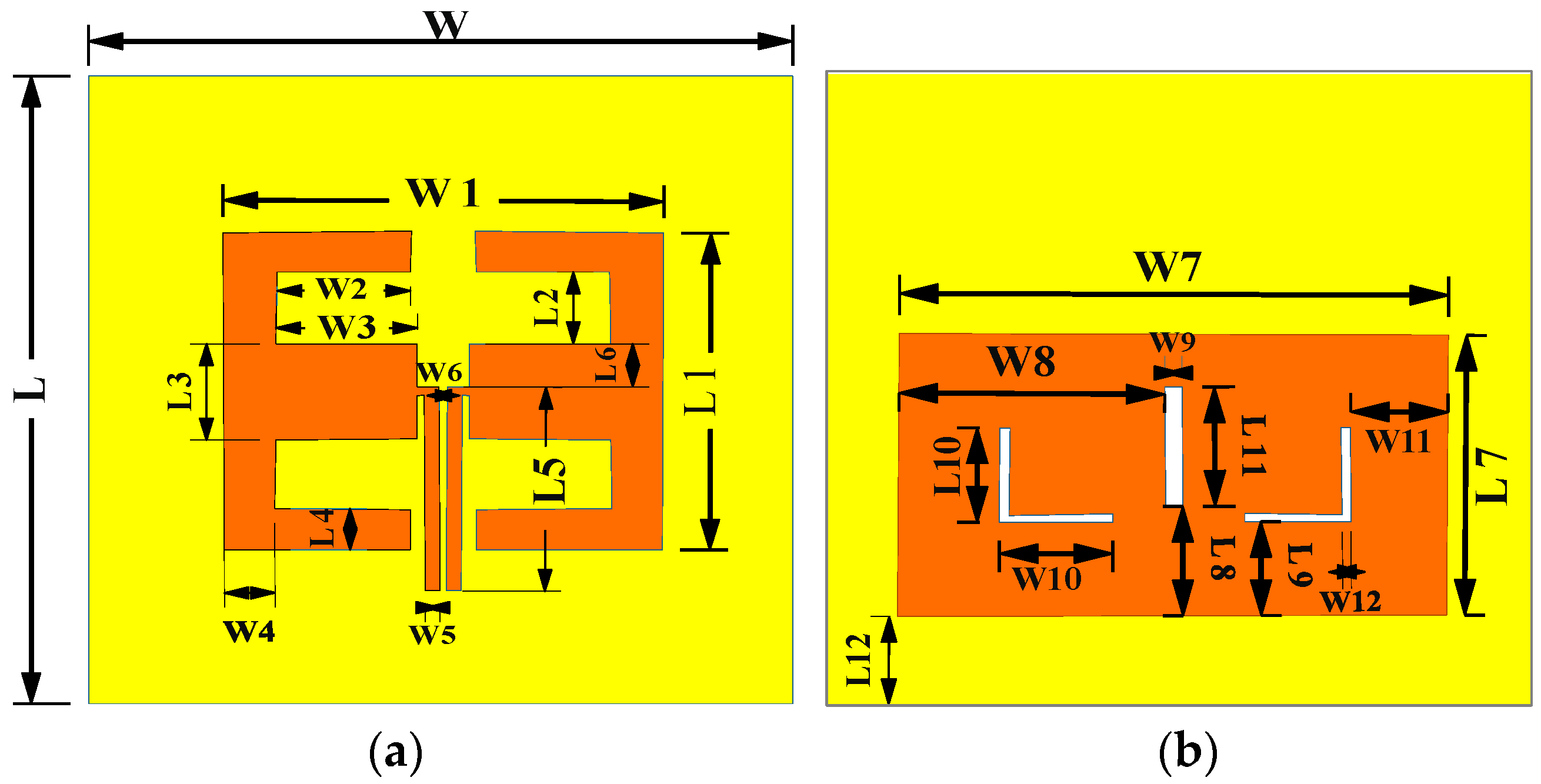
2. Antenna Geometry Configuration and Substrate Selection

A multiband dipole antenna which consists of two symmetrical E-shaped patches backed by a rectangular patch with L-shaped cuts was designed on a denim (low loss) substrate with a relative dielectric constant of 1.7 and loss tangent of tanδ = 0.024 [29]. The proposed antenna geometry is presented in Figure 1, and details of the antenna dimensions are given in Table 1. In the fabrication of the antenna, copper adhesive tape (layer thickness of 0.035 mm), which is a common hardware, was utilised. The antenna was small in size, and its overall conductive area, including the rectangular patch, was 62 × 46 mm 2 . The substrate size did not adversely affect the antenna performance because it was bigger than the conductive area.

3. Results and Discussions

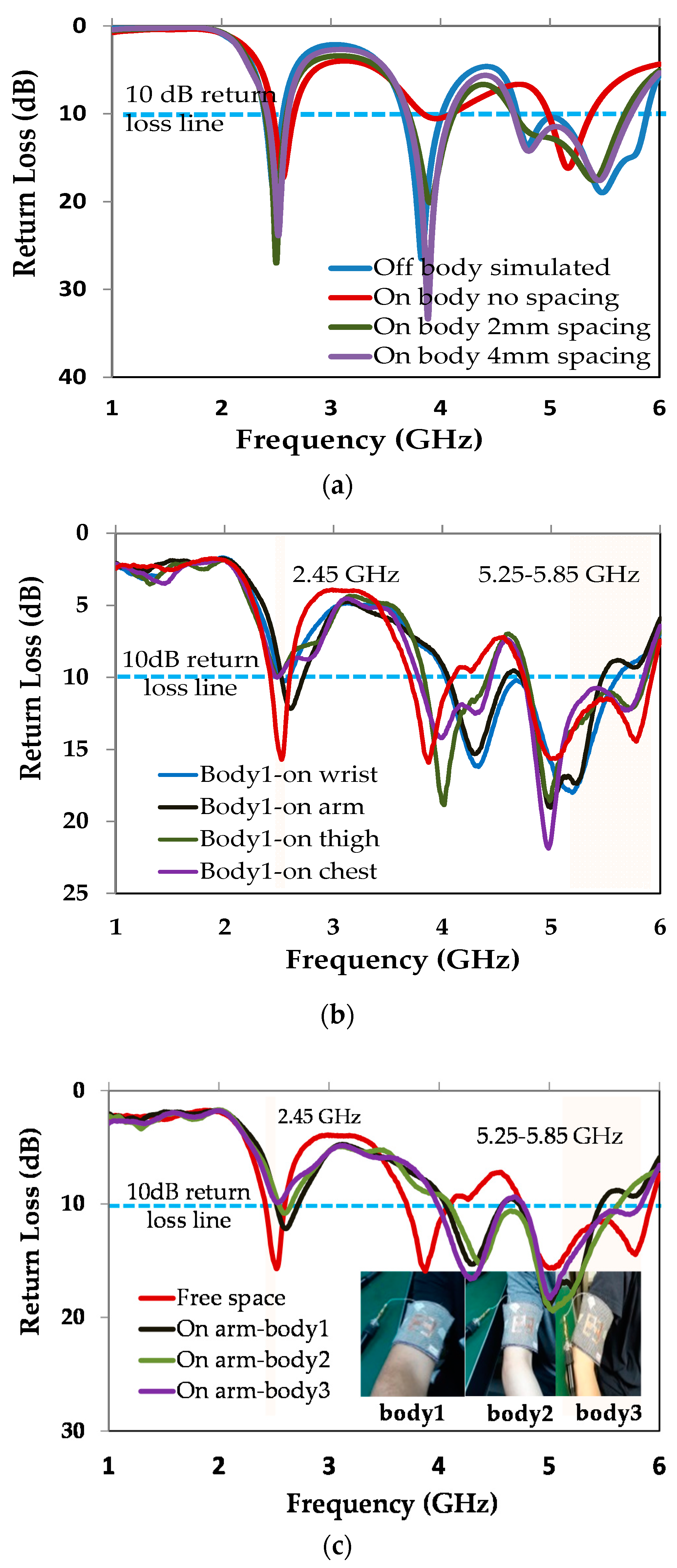
3.1. Return Loss Simulation and Measurements

After fabricating the prototype of the optimised antenna structure, shown in Figure 2a, an N5230A PNA-L (Keysight Technologies, Santa Rosa, CA, USA) network analyser was used to measure the return loss. A minicoaxial RF cable (IPEX MHF1 1.13 mm Coax RF Cable with 50 Ω impedance, the inner conductor diameter of which was 0.24 mm and the outer conductor diameter was 0.9 mm) was used to feed the antenna. As shown in Figure 2b, the measured return loss was in excellent agreement with the simulated results. The antenna impedance bandwidth covered ISM 2.4 and 5.75 GHz bands as well as WLAN 5.25 GHz applications. The 10 dB reference return loss showed that voltage standing wave ratio (VSWR) at the input of the antenna was less than 2; hence, more than 88% of the excited power was accepted by the antenna.

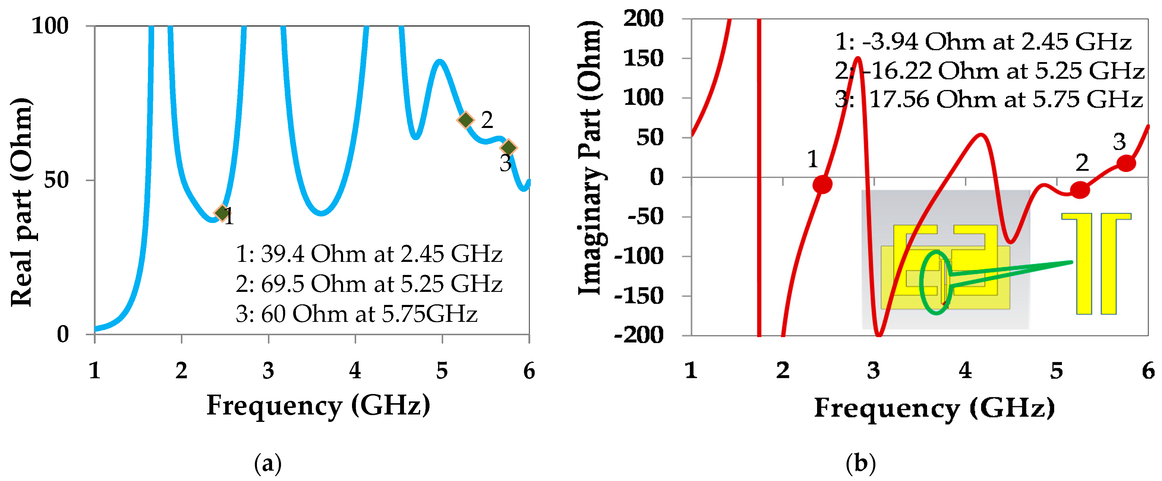
3.2. Antenna Input Impedance

Figure 3 shows the input impedance of the microstrip feed line. The feed line was excited by a 50 Ω discrete port. The feeding mechanism presented a method equivalent to the coplanar strips (CPS). Since the CPS feeding lines were separated by only a 1 mm gap, the parallel microstrip lines were coupled. Increasing the gap between them would change the value of the parasitic components existed between the the two microstrip lines. As a result, the input impedance would be affected.

3.3. Surface Current Distribution and Parametric Study

The antenna layout and simulated current distributions are presented in Figure 4. As it can be seen, both the E-shaped dipole and the rectangular patch contributed considerably to supporting the desired frequency bands. In contrast to the 2.45 GHz and 5.25 GHz frequency bands, the 5.75 GHz band was mainly supported by the E-shaped patches and not the rectangular patch (see Figure 5). In addition, due to the presence of parasitic capacitors, the impedance of the feed line was also affected. For example, if the gap was increased to 3 mm, the simulated return loss showed that the highest frequency band was detuned and impedance mismatching increased too. Therefore, the rectangular patch with L-shaped cuts enhanced the antenna bandwidth and the application frequency bands. The presence of the L-shaped cuts in the rectangular patch, on the one hand, has resulted in impedance mismatch at the 5.25 GHz band, but on the other hand, it has improved impedance matching at 5.75 GHz band.

3.4. Radiation Pattern of the Antenna

The xy, xz and yz planes of the prototyped antenna radiation pattern were measured in an anechoic chamber room, as shown in Figure 6. Comparison of the free space simulated and measured radiation pattern at 2.45 GHz, 5.25 GHz and 5.75 GHz central frequencies is shown in Figure 7a–c, respectively. Good agreement was found between the simulated and measured results. The antenna had linear polarisation and the electric field vectors oscillated in yz plane with propagation direction towards the z-axis. Because the antenna is proposed to support data communication for internet of things (IoT) systems in healthcare, it is important for the wearable antenna to have a semi- or omnidirectional radiation pattern. This will support efficient data transmission or reception when the person is walking or standing in both xz and yz plane propagation. Also, when the person is sleeping or lying down, both the xy and xz planes are considered as supporting propagation planes. The results showed that the dipole patch antenna had a semi-omnidirectional pattern.

3.5. Influence of Bending on Antenna Performance

For real-life requirements, the flexibility and user comfortability of wearable antennas are highly considered. A wearable antenna’s behaviour should be studied in terms of durability and robustness after applying different deformations. Figure 8 presents the comparison results for measured return loss when the antenna was relaxed and when it was bent over foam cylinders of different radii (3 cm, 5 cm and 7 cm). The measured return loss results showed that the proposed antenna was highly robust and its performance remained stable over the supported frequency bands. No considerable detuning in the central frequencies was observed and the impedance bandwidth at the desired frequency bands remained the same as the relaxed condition measurement.

3.6. Antenna Behaviour in Proximity to the Human Body

In order to realise the behaviour of wearable antennas placed in proximity to the human body, approximate models for a special tissue or full human body models were used. A homogenous model having a parallelepipedic shape of 450 × 50 × 50 mm 3 only made of muscle tissue was used to observe the specific absorption rate (SAR) [35]. Then, for the purpose of comparison, a Duke full-body model was used. A custom three-layer body model consisting of muscle, fat and skin was used [36,37,38]. The electrical characteristics of the tissues were frequency dispersive. The customised body models were of different sizes. The overall sizes of the phantoms were 200 × 200 × 43 mm 3 and 120 × 120 × 76 mm 3 , respectively. A male voxel body model was used in the simulations to investigate the antenna behaviour [39]. However, due to the differences in the characteristics of real biological tissue and the modelled body tissue, the simulation results showed only approximate calculations of the antenna parameters. In addition, full models of the human body are complex and need super computers to reduce the simulation time.
In this study, we used custom body tissue made of three layers. The model was composed of a 20 mm thick muscle layer, a 2 mm thick fat layer and a 1 mm thick skin layer. The overall dimensions of the model were 80 × 80 × 23 mm 3 , which were smaller compared to those in the literature. The customised body tissue was not only used to investigate the influence of the human body on wearable antenna performance but also to assess the SAR, which determines the amount of energy absorbed by body tissues. Figure 9 shows the specific parts of the human body on which the wearable antenna was placed. Return loss measurements were carried out, and in Figure 10a, the return loss simulation results for different spacings between the antenna and the cubic body model are presented. Because the human body is a frequency-dispersive medium, when the antenna touches the skin, the higher frequency bands will be more influenced. However, adding spacing will improve the impedance bandwidth and impedance matching.
After fabrication, we investigated the influence of the human body on the wearable antenna by placing it on different parts of a real human body, such as the wrist, arm, leg and chest. In Figure 10b, the measured results of return loss are shown for when the antenna was relaxed off body and when the antenna was placed on a real body. Because of the antenna’s robustness, the supported application central frequencies were not detuned. There was good agreement between the on-body measured results and the off-body relaxed return loss results. Considering that the wearable antenna was designed to not only operate on one but any user, measurements of the antenna when placed on the arm of different users were carried out. As shown in Figure 10c, three other arm-mounted measurements were carried out on three volunteers. Again, the results were in great agreement with the off-body relaxed results. In Table 2, firstly, the simulated and measured gain and efficiency of the antenna in free space and off body are presented. Secondly, the simulated antenna gain and efficiency off body and on body are compared. Because the human body is a complex medium with a high dielectric constant, the antenna gain and efficiency were considerably degraded when the antenna was placed in proximity to the body tissue.

3.7. SAR Calculation

CST microwave studio was used to evaluate the SAR of the wearable antenna. To investigate maximum SAR, the antenna was placed on the skin layer of the cubic tissue and the antenna rectangular patch was in direct contact with the skin. Simulations for 2.45 GHz, 5.25 GHz and 5.75 GHz central frequencies in reference to different reference input powers starting from 25 mW up to 250 mW were carried out. IEEE/IEC 62704-1 averaged on 10 g was used to calculate the SAR value of the biological tissues. SAR was calculated as
SAR = σ | E | 2 ρ
where σ in S m is the tissue conductivity, E in V m is the electric field and ρ in Kg m 3 is the mass density of the tissue.
Peak values of a 10 g averaged SAR at different frequencies for different incident powers are presented in Table 3. Increasing reference power will result in a significant increase of the amount of energy absorbed in the tissue. Taking user safety into consideration, it is recommended to not excite the antenna with more than 100 mW in practice. The calculated peak values for SAR were still below <2 (W/Kg) according to International Electrotechnical Commission (IEC) standards for a 10 g average mass. The input power can be increased slightly if extra spacing is added by inserting a layer of denim fabric or a thin layer of foam substrate. In Figure 11, the three-dimensional SAR distributed patterns at 100 mW reference power along with the biological model cross section are presented.

4. Conclusions

In this study, a novel E-shaped dipole antenna was designed and fabricated. The overall size of the unit was small and suitably convenient for user comfortability. The proposed antenna can be integrated with clothing for IoT applications. The antenna is durable and presented robust performance under different bending conditions. The excellent agreement between the simulated return loss and measured results showed that the proposed antenna is a good choice to be used for wearable communications. A semi-omnidirectional radiation pattern by which IoT wearable electronics can communicate easily was achieved. Supported frequencies stayed in bands when the antenna was placed in proximity to different bodies. A significant drop in the antenna gain and radiation efficiency occurred when the unit was placed on different parts of the human body. The antenna had low SAR and it was in direct proportion to the input power. The 10 g averaged SAR stayed within standard limitations for up to 100 mW input reference power considering direct contact between the antenna and body tissue.

Author Contributions

H.I.A. made the main contributions regarding design, modelling, optimisation, measurements, writing and draft preparation. H.-C.Y. contributed to draft revision and proofreading and helped acquire funding. W.-S.C. contributed as a co-author by reviewing the draft and validating the results as well as providing the facility used for basic antenna parameter measurements.

Funding

This research received no external funding.

Acknowledgments

The authors would like to acknowledge Wha Yu Industrial Co., Ltd. for their support during the radiation pattern measurements of the antenna.

Conflicts of Interest

The authors declare no conflict of interests.

References

  1. Sugiyama, H.; Goto, H.; Iwasaki, H. Wearable Finger Ring Dual Band Antenna Made of Fabric Cloth for BAN Use. In Proceedings of the 2012 Asia Pacific Microwave Conference Proceedings, Kaohsiung, Taiwan, 4–7 December 2012. [Google Scholar]
  2. Goto, H.; Iwasaki, H. A low profile wideband monopole antenna with double finger ring for BAN. In Proceedings of the 2011 IEEE-APS Topical Conference on Antennas and Propagation in Wireless Communications, Torino, Italy, 12–16 September 2011. [Google Scholar]
  3. Cihangir, A.; Luxey, C.; Jacquemod, G.; Pilard, R.; Gianesello, F.; Whittow, W.G.; Panagamuwa, C.J. Investigation of the effect of metallic frames on 4G eyewear antennas. In Proceedings of the 2014 Loughbrgh Antennas and Propagation Conference, Loughborough, UK, 10–11 November 2014. [Google Scholar]
  4. Su, S.W.; Hsieh, Y.T. Integrated Metal-Frame Antenna for Smartwatch Wearable Device. IEEE Trans. Antennas Propag. 2015, 63, 3301–3305. [Google Scholar] [CrossRef]
  5. Hong, W.; Lim, S.; Ko, S.; Kim, Y.G. Optically Invisible Antenna Integrated Within an OLED Touch Display Panel for IoT Applications. IEEE Trans. Antennas Propag. 2017, 65, 3750–3755. [Google Scholar] [CrossRef]
  6. Ashyap, A.Y.I.; Abidin, Z.Z.; Dahlan, S.H.; Majid, H.A.; Seman, F.C. A Compact Wearable Antenna Using EBG for Smart-watch Applications. In Proceedings of the 2018 Asia-Pacific Microwave Conference (APMC), Kyoto, Japan, 6–9 November 2018. [Google Scholar]
  7. Huang, H.S.; Su, H.L.; Chen, S.L. Multiband antennas for GPS/GSM1800/Bluetooth/Wi-Fi smart watch applications. In Proceedings of the 2017 IEEE International Conference on Computational Electromagnetics (ICCEM), Kumamoto, Japan, 8–10 March 2017. [Google Scholar]
  8. Cheng, C.M.; Chen, W.S.; Lin, G.Q.; Chen, H.M. Four antennas on smart watch for GPS/UMTS/ WLAN MIMO application. In Proceedings of the 2017 IEEE International Conference on Computational Electromagnetics (ICCEM), Kumamoto, Japan, 8–10 March 2017. [Google Scholar]
  9. Salman, L.K.H.; Talbi, L. Dual Band G-shape wearable cuff button antenna for ISM bands applications. In Proceedings of the 2010 IEEE Antennas and Propagation Society International Symposium, Toronto, ON, Canada, 11–17 July 2010. [Google Scholar]
  10. Sreelakshmy, R.; Vairavel, G. Novel cuff button antenna for dual-band applications. ICT Express 2018, 5, 26–30. [Google Scholar] [CrossRef]
  11. Chen, S.J.; Kaufmann, T.; Ranasinghe, D.C.; Fumeaux, C. A Modular Textile Antenna Design Using Snap-on Buttons for Wearable Applications. IEEE Trans. Antennas Propag. 2016, 64, 894–903. [Google Scholar] [CrossRef] [Green Version]
  12. Yang, H.C.; Azeez, H.I.; Wu, C.K.; Chen, W.S. Design of a fully textile dualband patch antenna using denim fabric. In Proceedings of the 2017 IEEE International Conference on Computational Electromagnetics (ICCEM), Kumamoto, Japan, 8–10 March 2017. [Google Scholar]
  13. Singh, N.K.; Singh, V.K.; Naresh, B. Textile Antenna for Microwave Wireless Power Transmission. Procedia Comput. Sci. 2016, 85, 856–861. [Google Scholar] [CrossRef] [Green Version]
  14. Sreelakshmy, R.; Ashok Kumar, S.; Shanmuganantham, T. A wearable type embroidered logo antenna at ISM band for military applications. Microw. Opt. Technol. Lett. 2017, 59, 2159–2163. [Google Scholar] [CrossRef]
  15. Corchia, L.; Monti, G.; Benedetto, E.D.; Tarricone, L. Wearable Antennas for Remote Health Care Monitoring Systems. Int. J. Antennas Propag. 2017, 2017, 1–11. [Google Scholar] [CrossRef]
  16. Kanaparthi, S.; Sekhar, V.R.; Badhulika, S. Flexible, eco-friendly and highly sensitive paper antenna based electromechanical sensor for wireless human motion detection and structural health monitoring. Extrem. Mech. Lett. 2016, 9, 324–330. [Google Scholar] [CrossRef]
  17. Affendi, N.A.M.; Alias, N.A.L.; Razali, N.M.; Awang, Z.; Samsuri, A. Flexible antennas using a new material. In Proceedings of the 2014 Asia-Pacific Microwave Conference, Sendai, Japan, 4–7 November 2014. [Google Scholar]
  18. Trajkovikj, J.; Zurcher, J.F.; Skrivervik, A.K. Soft and flexible antennas on permittivity adjustable PDMS substrates. In Proceedings of the 2012 Loughborough Antennas & Propagation Conference, Loughborough, UK, 12–13 November 2012. [Google Scholar]
  19. Rahman, A.; Islam, M.T.; Singh, M.J.; Kibria, S.; Akhtaruzzaman, M. Electromagnetic Performances Analysis of an Ultra-wideband and Flexible Material Antenna in Microwave Breast Imaging: To Implement A Wearable Medical Bra. Sci. Rep. 2016, 6, 1–11. [Google Scholar] [CrossRef]
  20. Porter, E.; Bahrami, H.; Santorelli, A.; Gosselin, B.; Rusch, L.A.; Popovic, M. A Wearable Microwave Antenna Array for Time-Domain Breast Tumor Screening. IEEE Trans. Med. Imaging 2016, 35, 1501–1509. [Google Scholar] [CrossRef]
  21. Curto, S.; Prakash, P. Design of a compact antenna with flared groundplane for a wearable breast hyperthermia system. Int. J. Hyperth. 2015, 31, 726–736. [Google Scholar] [CrossRef] [PubMed] [Green Version]
  22. Shrestha, S.; Agarwal, M.; Hemati, A.; Ghane, P.; Varahramyan, K. Breast tumour detection by flexible wearable antenna system. Int. J. Comput. Aided Eng. Technol. 2012, 4, 499–516. [Google Scholar] [CrossRef]
  23. Guay, P.; Gorgutsa, S.; Larochelle, S.; Messaddeq, Y. Wearable contactless respiration sensor based on multi-material fibers integrated into textile. Sensors 2017, 17, 1050. [Google Scholar] [CrossRef] [PubMed]
  24. Othman, N.; Samsuri, N.A.; Rahim, M.K.A.; Kamardin, K. Design and analysis of flexible bow-tie antenna for medical application. J. Electr. Eng. 2017, 16, 17–21. [Google Scholar]
  25. Thalmann, T.; Popović, Z.; Notaros, B.M.; Mosig, J.R. Investigation and design of a multi-band wearable antenna. In Proceedings of the 2009 3rd European Conference on Antennas and Propagation, Berlin, Germany, 23–27 March 2009. [Google Scholar]
  26. Zeouga, K.; Osman, L.; Gharsallah, A.; Gupta, B. Truncated patch antenna on jute textile for wireless power transmission at 2.45 GHz. Int. J. Adv. Comput. Sci. Appl. 2018, 9, 301–305. [Google Scholar] [CrossRef]
  27. Gupta, N.; Singh, V.K.; Ali, Z.; Ahirwar, J. Stacked Textile Antenna for Multi Band Application Using Foam Substrate. Procedia Comput. Sci. 2016, 85, 871–877. [Google Scholar] [CrossRef] [Green Version]
  28. Hertleer, C.; Rogier, H.; Vallozzi, L.; Van, L.L. A textile antenna for off-body communication integrated into protective clothing for firefighters. IEEE Trans. Antennas Propag. 2009, 57, 919–925. [Google Scholar] [CrossRef]
  29. Azeez, H.I.; Chen, W.S.; Wu, C.K.; Cheng, C.M.; Yang, H.C. A simple resonance method to investigate dielectric constant of low loss substrates for smart clothing. Sens. Mater. 2018, 30, 595–608. [Google Scholar] [CrossRef]
  30. Ouyang, Y.; Chappell, W.J. High frequency properties of electro-textiles for wearable antenna applications. IEEE Trans. Antennas Propag. 2008, 56, 381–389. [Google Scholar] [CrossRef]
  31. Ivsic, B.; Bonefacic, D. Implementation of conductive yarn into wearable textile antennas. In Proceedings of the 2014 24th International Conference Radioelektronika, Bratislava, Slovakia, 15–16 April 2014. [Google Scholar]
  32. Kiourti, A.; Lee, C.; Volakis, J.L. Fabrication of Textile Antennas and Circuits with 0.1 mm Precision. IEEE Antennas Wirel. Propag. Lett. 2016, 15, 151–153. [Google Scholar] [CrossRef]
  33. Chauraya, A.; Whittow, W.G.; Vardaxoglou, J.C.; Li, Y.; Torah, R.; Yang, K.; Beeby, F.; Tudor, J. Inkjet printed dipole antennas on textiles for wearable communications. IET Microw. Antennas Propag. 2013, 7, 760–767. [Google Scholar] [CrossRef] [Green Version]
  34. Cook, B.S.; Shamim, A. Utilizing wideband AMC structures for high-gain inkjet-printed antennas on lossy paper substrate. IEEE Antennas Wirel. Propag. Lett. 2013, 12, 76–79. [Google Scholar] [CrossRef]
  35. Chahat, N.; Zhadobov, M.; Sauleau, R.; Ito, K. A compact UWB antenna for on-body applications. IEEE Trans. Antennas Propag. 2011, 59, 1123–1131. [Google Scholar] [CrossRef]
  36. Mandal, D.; Pattnaik, S.S. Wide CPW-Fed Multiband Wearable Monopole Antenna with Extended Grounds for GSM/WLAN/WiMAX Applications. Int. J. Antennas Propag. 2019, 2019, 1–15. [Google Scholar] [CrossRef]
  37. Mandal, D.; Pattnaik, S.S. Quad-Band Wearable Slot Antenna With Low Sar Values for 1.8 Ghz Dcs, 2.4 Ghz Wlan and 3.6/5.5 GHz Wimax Applications. Prog. Electromagn. Res. B 2018, 81, 163–182. [Google Scholar] [CrossRef]
  38. Casula, G.; Montisci, G. A Design Rule to Reduce the Human Body Effect on Wearable PIFA Antennas. Electronics 2019, 8, 244. [Google Scholar] [CrossRef]
  39. Vatankhah Varnoosfaderani, M.; Thiel, D.V.; Lu, J. A Wideband Slot Antenna in a Box for Wearable Sensor Nodes. IEEE Antennas Wirel. Propag. Lett. 2015, 1225, 494–1497. [Google Scholar] [CrossRef]
Figure 1. Schematic of the proposed antenna: (a) E-shaped main radiating elements; (b) Rectangular patch with L-shaped cuts.
Electronics 08 00665 g001
Figure 2. (a) Photo of the antenna prototype connected to the network analyser using a minicoaxial cable; (b) Comparison of simulated and measured return loss in free space.
Electronics 08 00665 g002
Figure 3. Antenna input impedance: (a) Real part; (b) Imaginary part.
Electronics 08 00665 g003
Figure 4. Current distribution: (a) Antenna layout; (b) At 2.45 GHz; (c) At 5.25 GHz; (d) At 5.75 GHz.
Electronics 08 00665 g004
Figure 5. Parameter test observations of the antenna structure.
Electronics 08 00665 g005
Figure 6. Photos of the antenna prototype in an anechoic chamber room: (a) The chamber room; (b) Antenna being tested.
Electronics 08 00665 g006
Figure 7. Simulated and measured radiation patterns of the antenna in free space when relaxed at: (a) 2.45 GHz, (b) 5.25 GHz and (c) 5.75 GHz.
Electronics 08 00665 g007aElectronics 08 00665 g007b
Figure 8. Measured behaviour of the antenna under different deformations.
Electronics 08 00665 g008
Figure 9. Photos of antenna measurements on different locations (body 1): (a) Arm, (b) Wrist, (c) Chest and (d) thigh.
Electronics 08 00665 g009
Figure 10. On body measurements: (a) Influence of the biological model on the antenna’s performance (b) In proximity to the human body 1 and (c) on the arm of different bodies.
Electronics 08 00665 g010
Figure 11. Specific absorption rate (SAR) pattern at 100 mW: (a) 2.45 GHz; (b) 5.25 GHz; (c) 5.75 GHz; (d) Custom 3D layer model.
Electronics 08 00665 g011
Table 1. Dimensions of the proposed antenna.
ParameterValue (mm)ParameterValue (mm)ParameterValue (mm)ParameterValue (mm)ParameterValue (mm)
L140L65.5L1115W316W830
L29L736L1212W46W92
L312L814L, W80W51.5W1012
L45L912W150W61W1111
L525.5L1010W215W762W121
Table 2. On-body and off-body comparison of simulated and measured antenna gain and radiation efficiency.
Centre Frequency (GHz)Free Space Simulated Gain (dBi)On-Body Simulated Gain (dB)Free Space Measured Gain (dB)Free Space Simulated Rad. Eff. (%)On-Body Simulated Rad. Eff. (%)Free Space Measured Rad. Eff. (%)
2.452.13−121.26792.4340
5.256.134.52.338421.645.3
5.753.80.62.647911.339.7
Table 3. Simulated average specific absorption rate (SAR) (10 g) peak value in W/kg.
Centre Frequency (GHz)Incident Power (mW)
255075100250
2.450.41140.82291.2341.654.11
5.250.3980.79591.191.593.98
5.750.4280.85611.281.714.28

