Automatic Configuration of OPC UA for Industrial Internet of Things Environments


Software Engineering Department, University of Granada, C/Periodista Daniel Saucedo Aranda s/n., 18071 Granada, Spain
*
Authors to whom correspondence should be addressed.
†
These authors contributed equally to this work.
Electronics 2019, 8(6), 600; https://doi.org/10.3390/electronics8060600
Submission received: 2 April 2019
/
Revised: 10 May 2019
/
Accepted: 20 May 2019
/
Published: 29 May 2019
(This article belongs to the Section Systems & Control Engineering)
Abstract
:Software technologies play an increasingly significant role in industrial environments, especially for the adoption of Industrial Internet of Things (IIoT). In this context, the application of mechanisms for the auto-configuration of industrial systems may be relevant for reducing human errors and costs in terms of time and money, improving the maintenance and the quality control. OPC UA (OLE for Process Control Unified Architecture) systems are usually integrated into an industrial system to provide a standard way for setting a secure and reliable data exchange between industrial devices of multiple vendors and software systems. In this paper, a novel mechanism for the auto-configuration of OPC UA systems is proposed from an initial setup of industrial devices interconnected to a basic Ethernet network. The auto-configuration of the OPC UA is self-managed over the TCP/IP protocol. This mechanism allows automating the configuration process of the OPC UA server automatically from the programmable logic controller (PLC) devices connected to a basic Ethernet network. Once the PLC devices are identified, they exchange information directly with OPC using a Modbus protocol over the same Ethernet network. To test the feasibility of this approach, a case study is prepared and evaluated.
1. Introduction
Nowadays the industrial systems must evolve in order to satisfy the continuous requirements that customers and the market need. In these specific environments, the software plays an increasingly significant role. Consequently, the application of a methodology for the software development process can become critical to fulfill these requirements. However, the adoption of software development methods is still quite slow in the industry [1].
The arrival of new hardware devices and software systems may present a higher degree of difficulty in integrating them into the industrial ecosystem in contrast to other application domains, such as IT or consumer electronics. Correspondingly, the support for introducing new software paradigms or devices are limited or simply non-existent. Therefore, the adoption of them requires great efforts to integrate, deploy, and execute in the industrial environment.
The rise of novel paradigms such as Industry 4.0 [2,3], IIoT (Industrial Internet of Things) [4,5] or Smart Factory [6,7] have further accentuated the need to achieve these strict requirements with new features such as interoperability, collaboration among systems, or the digitalization of a full industrial process [8]. In order to cope with the new challenges and software demands, it is necessary to work on the development of new paradigms and techniques that facilitate a better and productive evolution of industrial systems.
Therefore, industrial systems must continue to maintain a high level of reliability, safety, and security in order to enhance the production processes for large time periods. Any system failure or modification to the current production system can lead to costly production interruptions, which are time-consuming and have to be carried out manually. In both circumstances, the application of mechanisms based on the automatic reconfiguration of the systems without a manual intervention can reduce the efforts and time to make the system productive again [8].
Traditionally the reconfiguration or auto-configuration mechanisms (ACMs) in industrial systems have been focused mainly on the automatic detection of field devices such as sensors and actuators by a programmable logic controller (PLC) on a specific fieldbus (e.g., Ethernet and Profinet) [9,10,11,12]. The fieldbuses used in the industry have also evolved from serial communication interfaces (e.g., Profibus) to the current Real Time Ethernet (RTE) interfaces, taking Ethernet as the base communication technology (e.g., Profinet and EtherCAT) [13].
Some works propose the use of lower layer of TCP/IP protocols for the auto-configuration of industrial devices into the RTE network. For instance, Imtiaz et al. [14] propose an approach for the auto-configuration of industrial devices in the RTE network with the application of an auto-assignment of MAC-Addresses combined with a Link Layer Discovery Protocol (LLDP) at Layer-2, which discovers the device location in network topology by sending LLDP messages.
In contrast, in [15], the auto-configuration between industrial devices is achieved by the introduction of an ad-hoc channel that co-exists with RTE channels. The ad-hoc channel allows the automatic identification of an industrial device using a discovery mechanism WS-Discovery based on Service-Oriented Architecture (SOA) implemented in DPWS (Device Profiles for Web Service). Once the information of the industrial device is achieved, that industrial device can be connected to RTE channels automatically in order to exchange information. In a similar way, Durkop et al. [9] substitute WS-Discovery with OPC UA (OLE for Process Control Unified Architecture) as a discovery mechanism to identify industrial devices in the network.
All of the above auto-configuration proposals come to make effective the “Plug and Produce” (PnP) [16]. “Plug-and-Produce” is equivalent to the “plug-and-play” term usually employed in IT systems to specify devices that can simply be connected to the system and turned on, and will work without any human intervention. PnP is the key that will drive the smart-factory of tomorrow, where machines, production lines, and storage systems will collaborate within a network composed of cyber-physical systems (CPSs) [12]. In this way, these systems will be able to collaborate among them and perform tasks such as exchanging information, triggering actions, or controlling one another. Furthermore, Hammestringl et al. [12] carried out an analysis of the current industrial environments in order to establish the requirements that an architecture for industrial system should have to allow for automating the integration of PnP heterogenous field devices into PLCs in a unified manner.
Depending on the selected ACM mechanism, features such as flexibility, scalability, adaptability, and interoperability of the system can be enhanced [17]. The flexibility gives us the ability to add and remove devices from the network without manual configuration of them, regardless of the device vendor. The scalability provides the possibility to plug one or more devices without compromising the normal operation and quality of the system. The adaptability affords the capability to provide additional functionality to the system by connecting the device without manual configuration. Finally, the interoperability provides the ability to plug the device without any restriction as long as the interfaces to other systems are satisfied.
In this work, we have extended the PnP application beyond the industrial controllers, specifically between the PLCs and the software systems in charge of monitoring data processes. Generally, these software systems are managed by a SCADA (Supervisory Control and Data Acquisition) system or an OPC (Ole for Process Control) system, indistinctly; only OPC systems are considered from now on.
OPC systems, and specifically the last release OPC UA, plays an important role in current industry environments, and more specifically to give support to next IIoT environments [18,19]. Basically, they provide a standard way for setting secure and reliable data exchange between industrial devices of multiple vendors and software systems. This give us an interface or gateway that allows us to interact directly with PLC devices but outside of the stringent fieldbuses and field devices [20,21]. In fact, OPC UA can be considered the backbone protocol for the harmonization of different industrial automation networks and systems [19].
Once the PLC device is deployed and executed, the OPC UA system is connected to PLC using a standard Ethernet-based network by configuring the network address of the PLC and setting data variables that are mapped to the corresponding addresses on the same variables in the PLC device.
This process is usually not automated and therefore requires a greater or lesser effort depending on the number of variables to be configured. In fact, any interruption of the industrial process due to a modification of the controller, both the controller and the OPC UA system should necessarily be reconfigured manually. In these cases, it is necessary (i) to stop the installation, (ii) to reconfigure manually the PLC with the characteristics of the new device, (iii) to generate the new network address in the PLC, (iv) to restart the PLC, (v) to reconfigure the OPC UA with the new IP address of the PLC device if it has been replaced, (vi) to reassign the data variables of OPC UA with process variables of the PLC, and, finally, (vii) to restart OPC UA.
In this paper, a new auto-configuration mechanism for OPC systems based on the OPC UA standard is proposed. This mechanism allows automating the configuration process of the OPC UA server automatically from the PLC devices connected to a basic Ethernet network. Once the PLC devices are identified, they exchange information directly with OPC using a Modbus protocol over the same Ethernet network.
The main advantages of the proposed auto-configuration mechanism are as follows:
- The process information managed by the industrial device can be consulted directly on the OPC UA server, without having to carry out any configuration or parametrization task on the server itself.
- The OPC system and PLC devices can share the same Ethernet network with other industrial systems such as SCADA or MES (Manufacturing Executing System), among others. However, the communication between PLC devices and OPC are set independently using a Modbus TCP/IP protocol that coexists with the TCP/IP protocol.
- The proposed auto-configuration mechanism can reduce the effort and time required to configure OPC systems, especially when the number of variables is high. Furthermore, the number of errors made in the manual configuration can also be reduced.
Section 2 presents the involved technologies required to perform the auto-configuration mechanism proposed in this paper. Section 3 details the proposed auto-configuration mechanism as well as the architecture of industrial systems. A study case is shown based on the proposal and some results are discussed in Section 4. Finally, Section 5 contains the conclusions and suggests future work.
2. Background
2.1. Auto-Configuration in Industrial Environments
In general, the auto-configuration mechanisms allow the automatic configuration of devices, software systems, or communication protocols without manual intervention or with little human intervention within the context of a particular ecosystem. A concept closely related to auto-configuration is “plug-and-play” or its corresponding “plug-and-produce” in the industry [8,22]. This term is used to denote the ability of a device or system to connect, turn on, and immediately go to work by itself without any help, that is, an auto-configuring device. A PnP device or system has to be able to apply an auto-configuration mechanism in order to be available to work with other devices or systems.
In the IT domain, the PnP is a widespread paradigm in many technologies (e.g., USB and uPnP) applied to simplify the identification and interconnection of devices in home and office networking environments [23]. The PnP is also widely used at the application level to identify autonomous self-contained components, known as services, accessible to other services or applications by the public exposition of a contract or an API (Application Programming Interface) by means of Service-Oriented Architecture (SOA) or Resource-Oriented Architecture (ROA) [10,24,25]. In this context, the auto-configuration in service-oriented platforms is focused mainly on the application of a discovery mechanism that helps the identification of any service that has been previously registered in a Service Directory [26]. In addition, the presence of a service composition mechanism provides a list of discoverable services that each service must know before using them [27].
Some attempts to apply SOA at Device-Level in Industrial Automation were proposed in the context of the European project SIRENA [28] by the implementation of web services (e.g., DPWS) [10,29]. In this case, a decentralized discovery approach based on WS-Discovery (Web Services Dynamic Discovery) is used to find out the available devices by sending broadcast announcements over the Ethernet network [30,31]. An RTE network is then initialized to interconnect all discovered devices with the PLC.
Durkop et al. [11] proposes a similar discovery approach substituting the Service Directory by an OPC UA server. OPC UA then provides the meta-information of field devices required by the PLC before connecting them. According to [9], the auto-configuration process consists of the following stages:
- Discovery: Every new device must be discovered.
- Exchange of meta-information: The attributes of the new device must be detected and share with all other devices.
- Configuration: The system must be configured in accordance with the discovered devices and their features.
In a similar way to the above cases, the same procedure was applied to set the auto-configuration process for OPC-UA systems instead of configuring heterogeneous field devices into a PLC.
2.2. The OPC Systems and OPC UA
The OPC (OLE for Process Control) systems appeared in 1995 as an interoperable standard method for the secure and reliable exchange of data from industrial devices of multiple vendors as data sources to any client software application. In fact, OPC systems are platform-independent and provide a standard way of accessing data of industrial processes, avoiding the inconsistencies that specific drivers from different vendors can add to their own developments [32].
The last standard, OPC UA (OLE for Process Control, Unified Architecture), released in 2006, changes significantly with respect to classic OPC. It keeps providing a reliable and secure standard method for accessing information from process variables of industrial devices, improving considerably both transport mechanisms and data modeling [33].
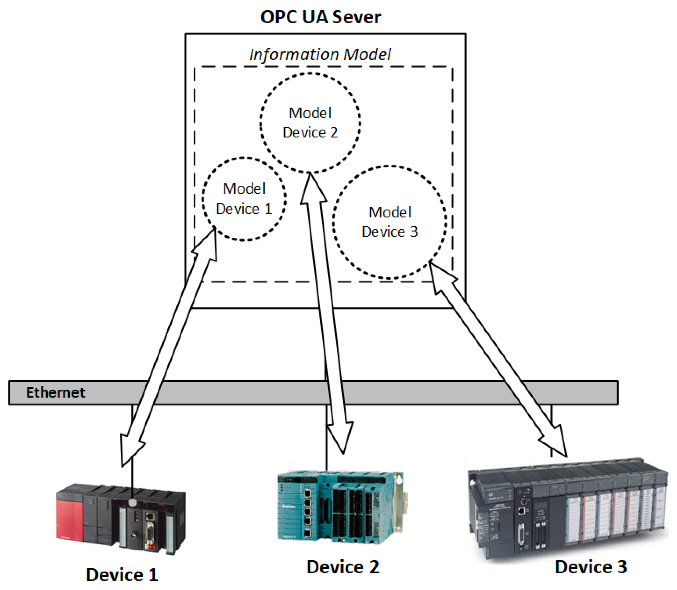
The access to OPC UA system is solved by a secure client-server architecture based on independent service-oriented platform and a publish/subscribe mechanism. The transport layer defines optimized mechanisms for transmitting and receiving data between OPC UA systems. The first version of OPC UA defines a binary mechanism based on the TCP protocol achieving high performance in intranet-based communications. In addition, other mechanisms are possible based on web services or HTTP/XML, providing access transparently to firewalls (Figure 1).
On the other hand, the data modeling provides a common framework to create a richer structured information model of the process information managed by industrial devices, facilitating the representation of complex data types hierarchically. This information model is stored in the address space of OPC UA server that can be exposed in a structured way to any OPC UA client such as an HMI.
2.3. Modbus
The Modbus [34] is an industrial communication protocol at the application layer that follows a master–slave topology in order to perform the communication between devices. Only one device, the master, can initiate request–response messages called queries to other devices (slaves) by sending a query to an individual slave or sending a broadcast query to all slaves. In contrast, slaves respond by supplying the requested data to the master, or by taking the action requested in the query. Usually, the slaves devices are peripheral devices (e.g., valve, measuring device, or I/O cards), while the master device is a PLC device or controller.
The communication in Modbus is set at the application layer, defining a set of rules for organizing and interpreting data, independently of the underlying physical layer. It is then possible to use Modbus over serial protocols (e.g., RS-485) or TCP/IP protocols on Ethernet. In any case, the message structure is always the same. A request contains the slave address, a function code, the data address of the first register requested, the number of requested registers, and the CRC, while the response is composed of the slave address, the function code, the number of data to be retrieved, the data, and the CRC. In the case of Modbus TCP/IP, the slave address is identified by an IP address. Some of the common Modbus function codes are as follows:
- FC1—read discrete output coils.
- FC2—read discrete input contacts.
- FC3—read analog output holding registers.
- FC4—read analog input registers.
- FC5—write single discrete output coil.
- FC6—write single analog output holding register.
- FC15—write multiple discrete output coils.
- FC16—write multiple analog output holding registers.
3. The Autoconfiguration of OPC UA
In this approach, a novel method is presented for auto-configuring the OPC UA server directly from the industrial PLCs connected to the system with a PnP perspective in order to provide an IIoT compatible system.
Traditionally, the implementations of OPC UA server provide drivers from multiple vendors to simplify the connection with industrial PLCs using a TCP/IP protocol in basic Ethernet. However, OPC UA does not know the addressing of process variables that industrial devices are handling. A human operator must configure manually the OPC UA server, defining the mapping of these process variables with the elements of the OPC UA information model. This procedure can involve great effort when thousands of process signals provided by industrial devices have to be configured. Accordingly, any change in the process variables of PLCs implies a full revision of the OPC information model in order to find and modify the mapping between PLCs and the OPC UA server. Therefore, the auto-configuration mechanism proposed in this paper attempts to automate the execution, configuration, and deployment of the OPC UA server without any manual intervention whenever necessary.
The auto-configuration of the OPC UA server is self-managed directly over the industrial PLCs connected to the OPC UA server using a basic Ethernet that can also be shared by other industrial software systems (e.g., OPC UA clients, HMI, SCADA, and MES). Firstly, the OPC-UA server has to scan the TCP/IP network in order to discover the IP address of possible new PLCs connected to the network. It obtains information of these PLCs as well as their process variables. This allows for building its information model in a specific OPC UA address space and configures after the corresponding mapping between elements of its information model with the addresses of the process variables in the PLCs. Once the OPC UA is configured, the OPC UA server actives the Modbus TCP/IP channel in order to enable the transmission of Modbus messages to the PLCs and maintain the two synchronized systems: the OPC UA server and the PLCs.
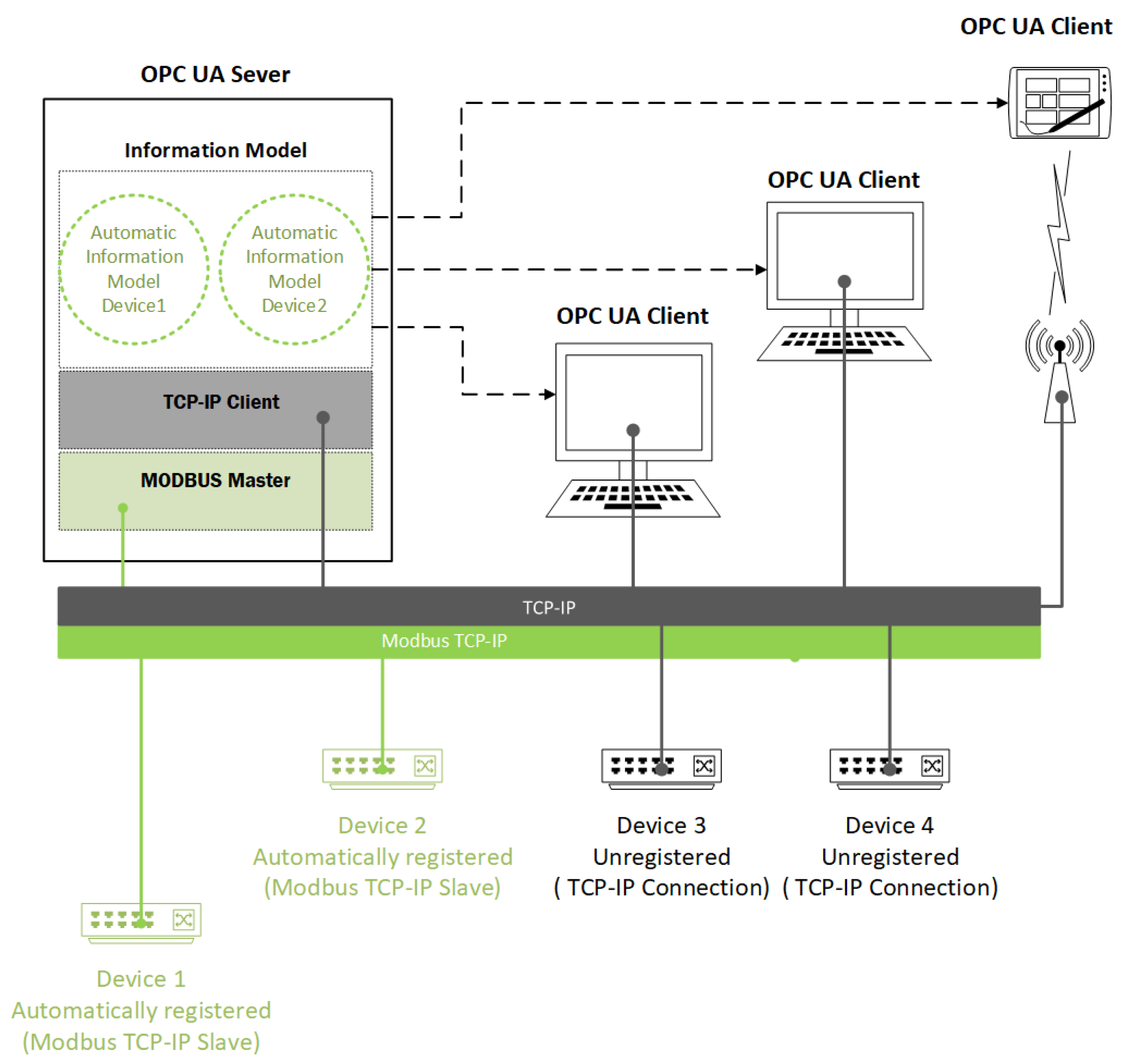
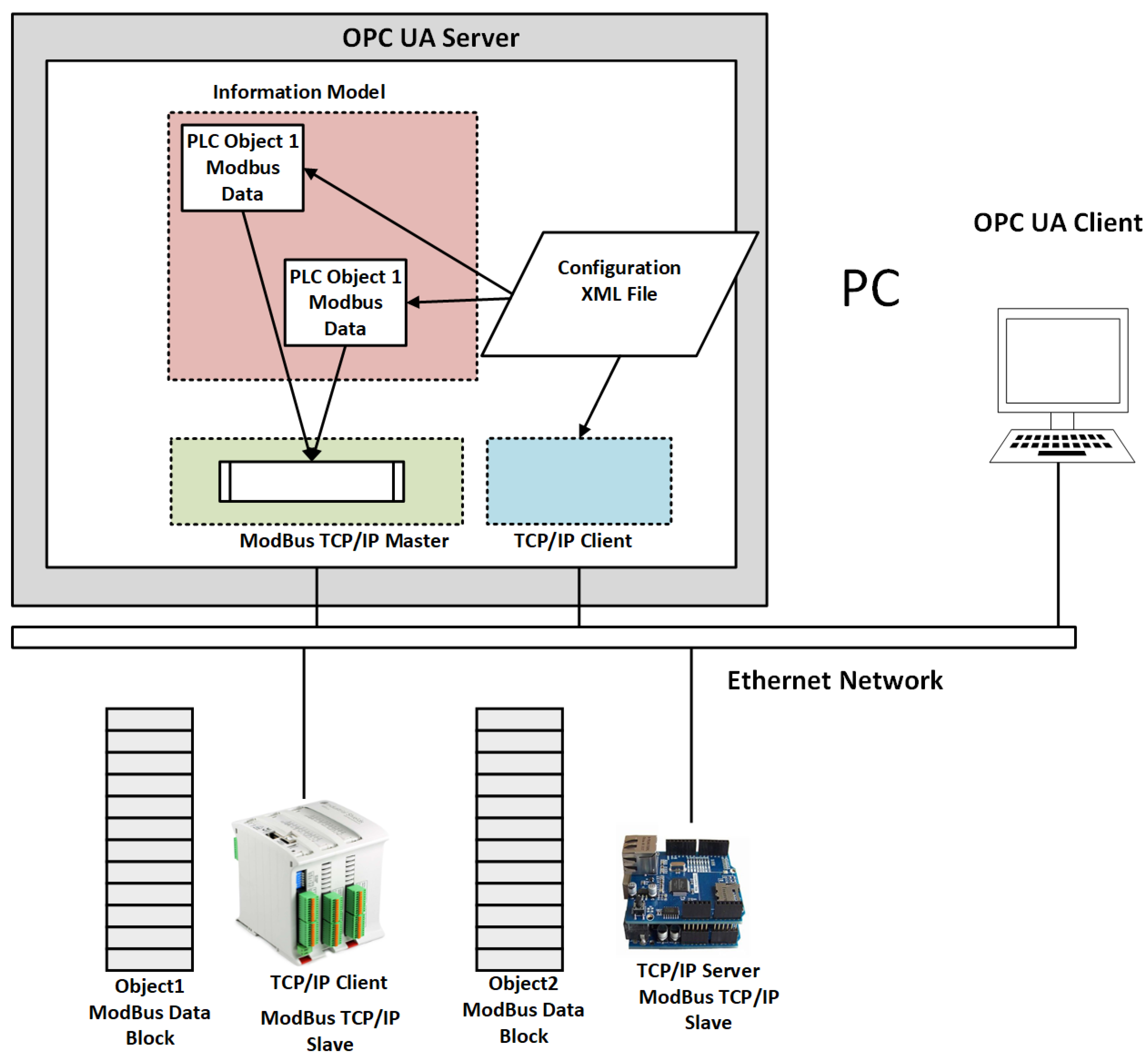
Figure 2 shows the components that form the architecture of an industrial system prepared for the application of the auto-configuration mechanism of the OPC UA server. The OPC UA server operates as a TCP/IP client in TCP/IP mode when it has to discover new PLC devices into the network. In contrast, the OPC UA acts as a Modbus master when it operates in Modbus mode. In this case, it polls periodically the Modbus slaves located in the network in order to synchronize the information model of the OPC UA server with the process variables of Modbus slaves. On the other hand, OPC UA clients (e.g., SCADA) can connect to the OPC UA server using TCP/IP when they have to monitor the process data of industrial devices through the information model of OPC UA.
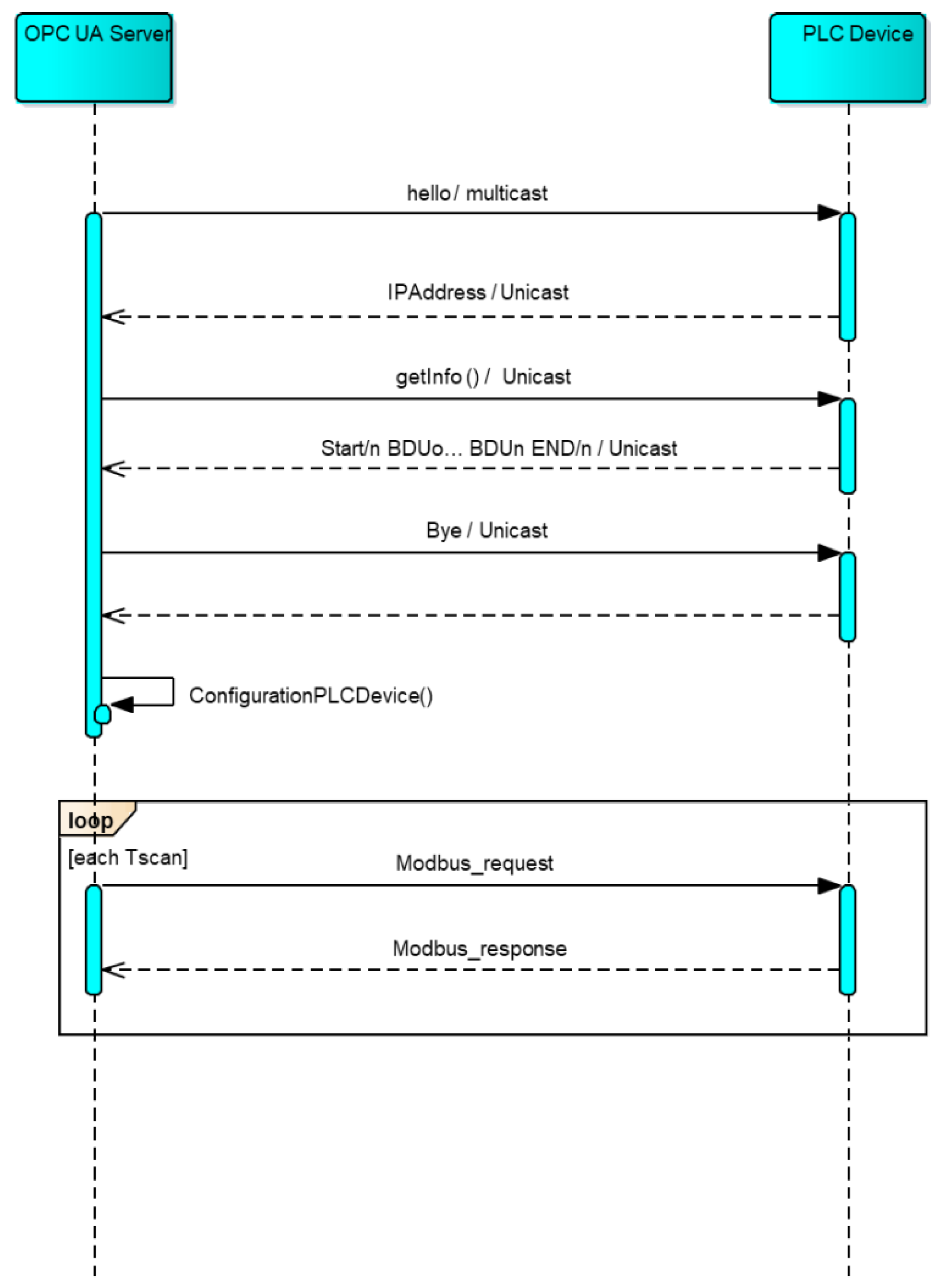
The novel mechanism for auto-configuration of OPC UA is composed of three stages. Figure 3 shows the message exchange flow between the industrial controller and the OPC UA server:
- Device Discovering. In this stage, the OPC UA server scans the network using the TCP/IP protocol for searching the available industrial PLCs or devices by sending “Hello” multicast messages periodically. When a PLC device captures one of these messages, it responds to the OPC UA server returning its current IP address (the default port of Modbus is 502). With this information, the OPC UA server can register that recognized device as a potential candidate. The IP address is necessary to establish the subsequent TCP/IP and Modbus TCP/IP communications in the following stages.
- Exchange of meta-information. In the second stage, OPC UA sends a query to the registered PLC in order to obtain information about the process variables that the OPC system can read on the detected PLC. Formally, this information is composed of a variable set of blocks of data units (BDUs) that begin with a START word and end with an END word:The elements in this structure are separated by a \n. Each BDU includes a block of process variables always of the same data unit that can be inspected/stored in the PLC device. A BDU is composed of three fields: datatype, offset, and datanumber. The datatype identifies the four basic data types recognized in Modbus: discrete output coils (1), discrete input contacts (2), analog output holding registers (3), and analog input registers (4). Second, the offset is the relative addressing with respect to a specific base address (depending on this case of the data type). Finally, the datanumber is the number of data that can be read or written of the same data type. For example, the BDU “4:300:10” specifies a block of 10 input registers that is located on the offset 300 of the base data address of input registers (0x30000, defined by Modbus).An example of the information returned by the PLC device is shown next:that includes 8 process data of output coils and input contacts, and 10 output holding registers and input registers at different offsets.“START\n1:0:8\n2:100:8\n3:200:10\n4:300:10\nEND\n”Finally, the OPC UA server sends a “bye” message indicating to the device that the TCP/IP communication channel can now be closed. At this point, the communication between the device and the OPC UA server is carried out using the Modbus protocol.
- Configuration of the device in OPC UA server. The information received from the PLC device must be built into the address space of the OPC UA server. The configuration is done in two steps:
- -
- Building of the information model in the OPC UA address space. With the information of the process variables of the PLC device and the type of those variables, the OPC UA server automatically generates one or more elements (in nodes) of the information model in its address space in order to expose the data of the process variables to any OPC UA client. This process takes advantage of the information model offered by the UA standard that provides rules for the creation of simple data types (e.g., integers, and float and string) or complex data types, such as objects with their attributes and methods [10]. The information model generated by the OPC UA server is stored into an XML file according to the schemas defined by the OPC Foundation [33]. The objects are structured by the name of the PLC plus the IP address. Next, an example of a float process variable is specified with the corresponding address.
<ObjectType SymbolicName="OpcUa:PLC01\_192.168.30.5"BaseType="OpcUa:BaseObjectType"><Children><Property SymbolicName="OpcUa:Address"DataType="OpcUa:String" /><Variable SymbolicName="OpcUa:value"DataType="OpcUa:Float" /></Children></ObjectType>
- -
- Mapping between PLC and OPC UA: Once the information model is built in an OPC UA address space, the correspondence between these elements and the process variables of the PLC is then configured. The configuration basically consists of setting the mapping between the address of each process variable and the corresponding element in the information model in the OPC UA address space as well as setting the read/write property of each element. This mapping between PLC and OPC UA is also stored in an XML document in order to reconfigure the OPC UA server when the server is going down.
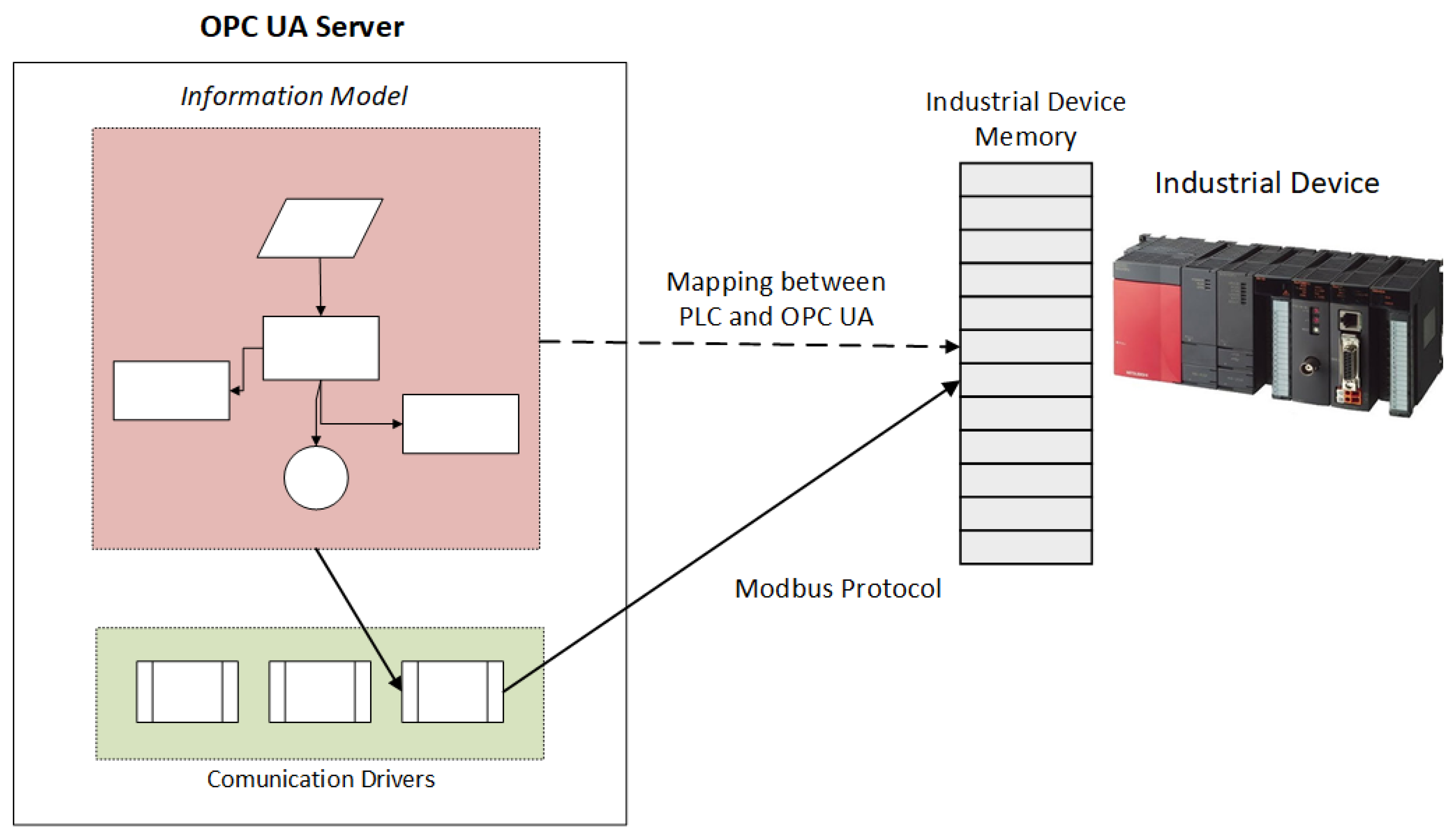
After the auto-configuration mechanism of the OPC UA server is finished, OPC UA server actives the communication driver of the Modbus protocol as a Modbus master in order to send periodically Modbus request–response messages for synchronizing the information model of OPC UA with the process variables of the PLC. Depending on the read/write property of each element in the information model of OPC UA, a request–response message is sent to update the process variables of the PLC or to retrieve the value of the process variables and consequently, in the last case, update the information model. Each Modbus request and response is built according to this standard. For instance, a request for reading input registers includes the function code FC4, the starting data address and the number of registers requested, while the response includes the same function code, the number of bytes read, and the contents of the read data addresses. Figure 4 shows a schematic of the process followed to send a request–response message to PLC.
4. Case Study
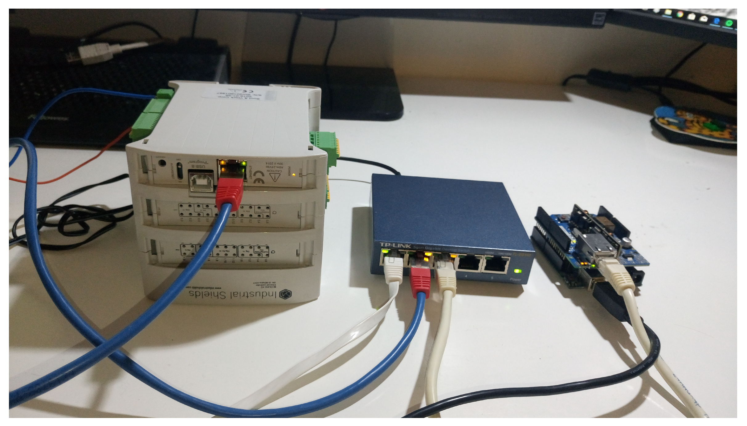
In order to test the proposed auto-configuration method, we prepared an industrial ecosystem in the lab. The ecosystem is composed of two industrial controllers (an M-DUINO PLC [35] and an Arduino One [36]), a switch, a desktop PC computer with an OPC UA server, and an OPC UA client running in another PC computer connected all of them to an isolated basic Ethernet network. The architecture of all the involved components in this case study can be seen in Figure 5, while a view of the physical devices used in the lab is shown in Figure 6.
4.1. Hardware
Two controllers were used for the preparation of the case study: an M-DUINO PLC and an Arduino ONE. The M-DUINO PLC from Industrial Shields [35] meets the specifications of an industrial controller, although it is programmable with a “processing” programming language such as the Arduino microcontroller family. The second one is not an industrial device, but it is introduced into the architecture to verify that the auto-configuration method works with several devices of the Arduino microcontroller family at the same time. Next, a summary of the main characteristics of the hardware used for the case study is described:
- M-DUINO PLC Arduino Ethernet 42 I/Os Analog/Digital PLUS [35]: This industrial PLC based on Arduino has 26 inputs: 12 analog inputs and 14 isolated digital inputs. The analog inputs can be switchable by software in 12 analog inputs (0–10 Vdc) or 12 digital input (5–24 Vdc). In addition, it has 16 isolated digital output; 6 of them are configurable as PWM output by software, and 6 of them are configurable as analog output by switch. Regarding connectivity, it has 1 ethernet port, 3 TTL ports, 1 RS-232 port, and 1 Hall/Full Duplex RS-485 port; it supports TCP/IP and RTU Modbus protocols.
- Arduino ONE [36]: The standard Arduino One includes by default 16 digital input/output (5 Vdc) and 4 analog input (5 Vdc). In addition an Ethernet Shield was installed for this controller to provide TCP/IP connectivity.
- OPC UA Server: The OPC UA server was deployed on a computer PC with an i5-4570 microprocessor at 3.20 GHZ with 8Gb RAM, and 1 GByte Ethernet, on which a Windows 10 (64 bits) operating system is running.
- OPC UA Client: The OPC UA client was deployed on another PC with an i5-3320M microprocessor at 2.60 GHZ with 4Gb RAM, 1 GByte Ethernet, with Windows 10 (64 bits).
4.2. Software
The implementation of each component of the industrial system was carried out to verify the behavior of the auto-configuration mechanism of the OPC UA server. A description of the libraries and the implemented software are summarized next for each hardware component:
- M-DUINO PLC Arduino and Arduino One. Both devices are implemented by the same programming language using the standard Arduino development framework v.1.8.5. Some Arduino standard libraries such as Ethernet, SPI, and w5100 and the Modbus TCP/IP library in C++ [37] were used to program the device controller. The program switches between a TCP/IP server and Modbus TCP/IP slave along its life cycle. In TCP/IP mode, the device controller is ready to respond when a hello multicast message is received, providing the required information to the OPC UA server during the auto-configuration of the OPC UA server. In Modbus TCP/IP mode, the device became a Modbus slave, responding to any request performed by the OPC UA server as a Modbus master.
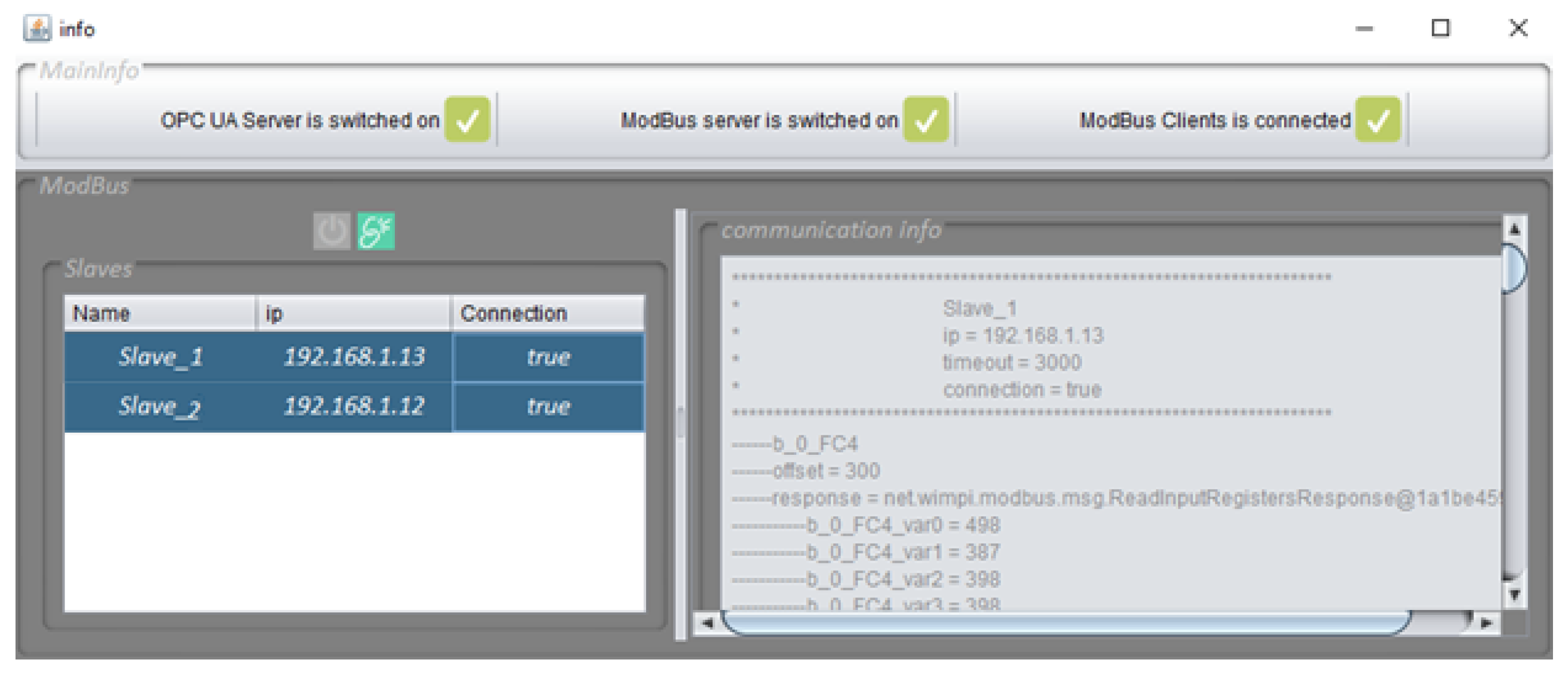
- OPC UA server. The OPC UA server was implemented completely in Java integrating three components: the OPC-UA server stack, the Modbus and TCP/IP communication stacks, and the OPC UA server manager. The OPC-UA server stack is provided by the OPC Foundation to implement the structure of the UA server, the support for data modeling, and the transport mechanism for providing a secure communication from OPC UA clients. The TCP/IP stack is used to scan the network at the first two stages of the OPC UA auto-configuration in order to find the PLC devices. Finally, an intuitive graphic user interface was developed for the OPC UA server manager that provides the ability to inspect the data and status of each element of the information model available on the OPC UA server. Although by default the OPC UA server attempts to find, register, and bind to PLCs automatically, a manual configuration was also possible. Figure 7 shows a screenshot of the program deployed on the OPC UA server.
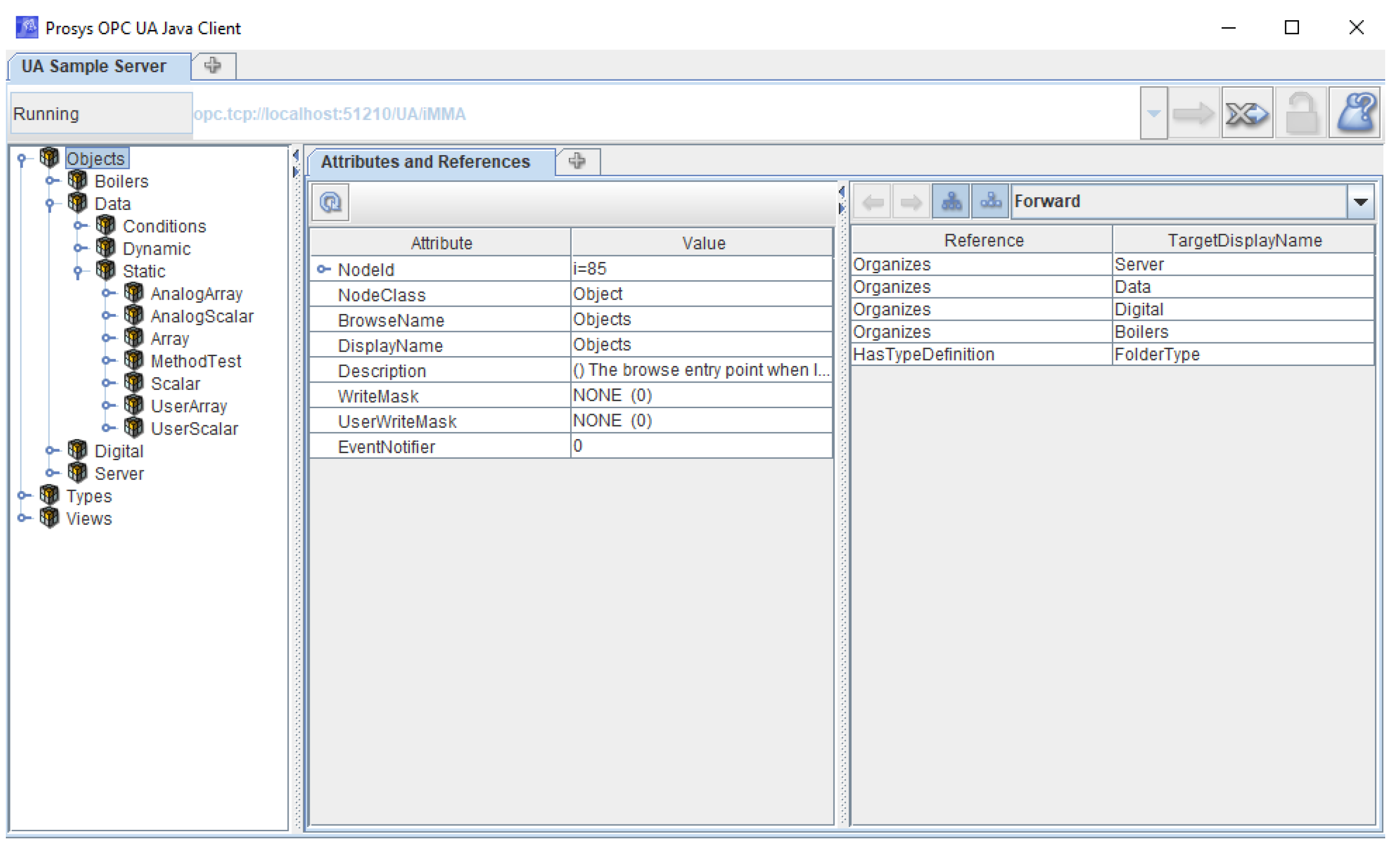
- OPC UA client. A commercial OPC UA client, Prosys OPC UA Client [38], was also used to test the accessing to the OPC UA server. The OPC UA client can see the process data by browsing through the nodes of the OPC UA address space. Depending on the (reading/writing) property of each node, the process data can be readable and writable. Figure 8 shows a screenshot of the OPC UA client.
In order to carry out the experiments, an initial deployment of the systems and devices was considered. The M-Duino PLC Arduino device was configured with 40 process variables in order to cover the 42 input/output available in the device, that is, 10 coils, 10 contacts, 10 analog inputs, and 10 analog outputs. In Modbus TCP/IP, it transmits data of the configured process variables each time a Modbus request is received from the OPC UA server. Similarly, the second device—the Arduino One—was configured with the same number of process variables.
The process variables provides data at the runtime of the sensor/actuator connected to the corresponding input/output. Some data of the process variables were generated by simulation. For example, some analog inputs were generated from an initial value of 50.0, incrementing 0.1 each time the process variable was read. When the process variable achieved a value of 100.0, it was reset again to the initial value of 50.0. On the other hand, some digital inputs (contacts) were simulated applying the negation of the actual value (HIGH or true) in each reading.
The OPC UA server was deployed and executed before devices in all experiments in order to control when the auto-configuration process was taken. In TCP/IP mode, the time interval of device discovery can be configured by the operator (by default this value was 1000 ms) or can be executed manually by the operator when a new PLC device is connected to the network. In Modbus TCP/IP mode, the scan rate can be configured to determine when the Modbus request–response messages are sent to PLC devices; in our case, it is set to 300 ms.
To verify that the auto-configuration mechanism of OPC UA is working properly, three different scenarios are presented in which the network traffic has been analyzed during the auto-configuration process.
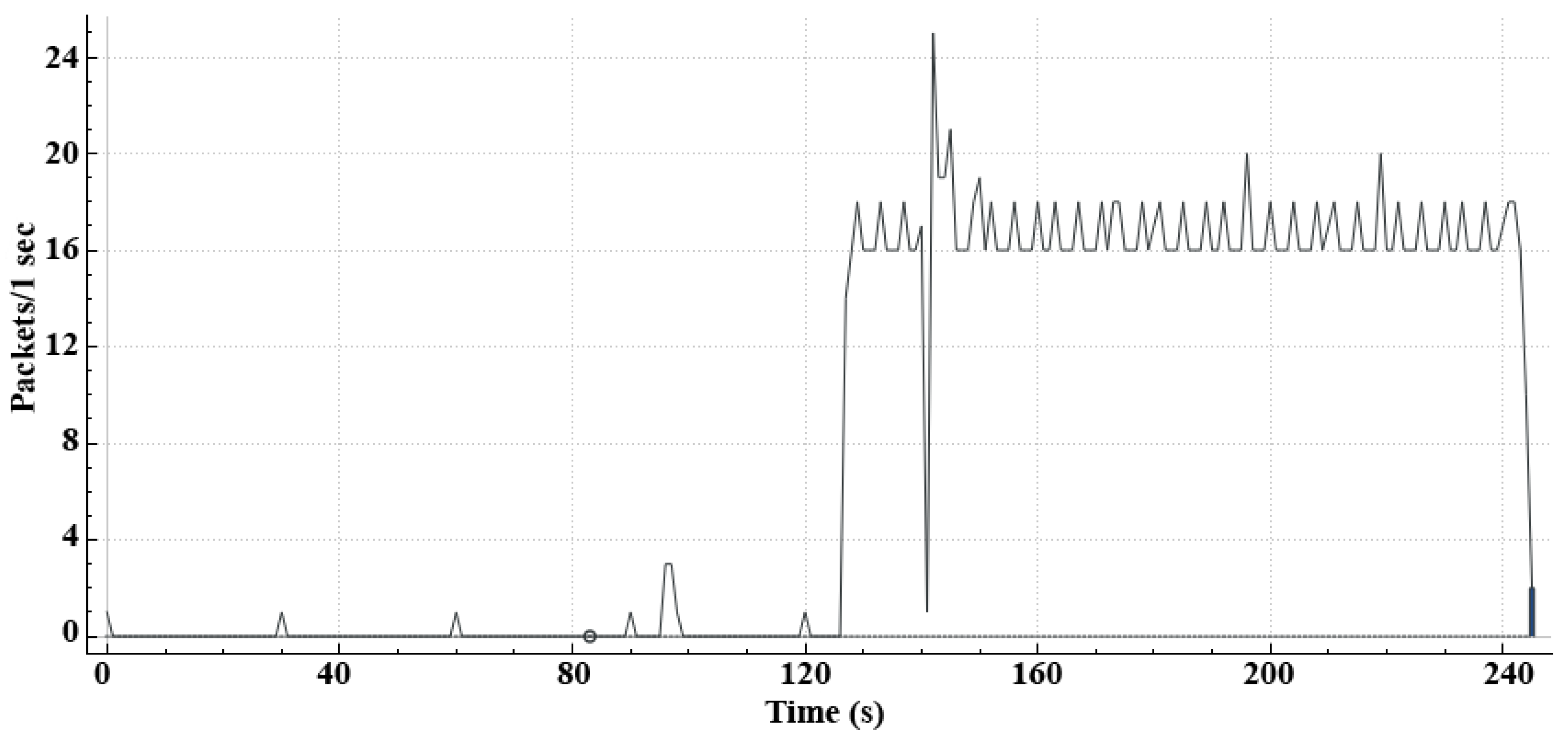
Scenario 1: In this case, the OPC UA server is deployed and executed before the M-DUINO device. Afterwards, the M-DUINO device was executed. An analysis of the network traffic was carried out during this process. Figure 8 shows the network traffic obtained by the auto-configuration mechanism plus the transmissions of Modbus request–response messages.
In this graph, the Y-axis represents packets per minute and the X-axis the time in seconds. As we can see in Figure 9, the small isolated peaks found at the beginning of the graph are consequence of the periodic scanning of the network caused by OPC UA server for looking for a possible industrial device. When a PLC device was connected to the network, an increase in the packet traffic was then achieved. The first highest peak was obtained when the PLC device was detected and the second highest peak when the device information was sent to OPC UA server. After that, the packet traffic was constant because of the data exchange in Modbus, with some periodic peaks.
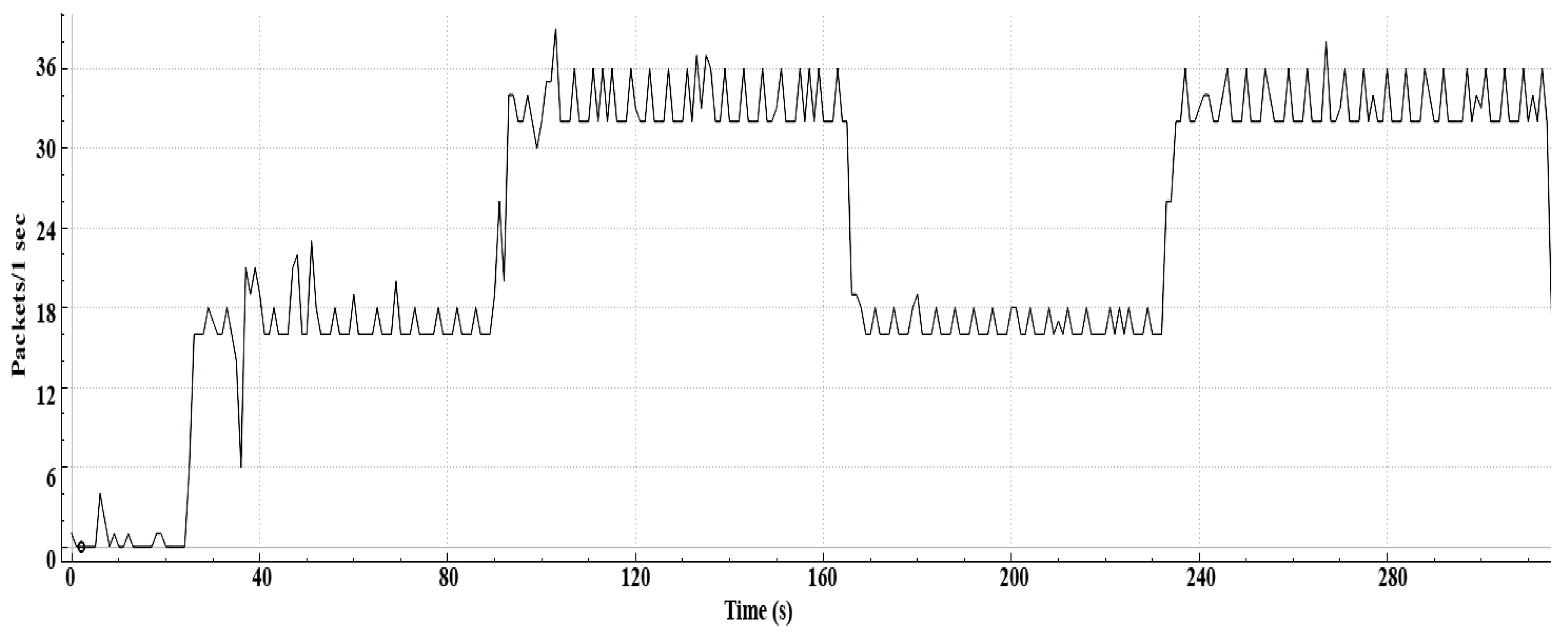
Scenario 2: In this case, the OPC UA server was also started before the industrial devices. Subsequently, two industrial devices were connected sequentially in order to study how it affects network traffic. Finally, the disconnection and reconnection of one of these industrial devices was tested over a time interval. Figure 10 shows the network traffic obtained in this case.
Similar to Scenario 1, an increase in the network traffic was obtained when the first industrial device was discovered by the OPC UA server. When the second device was connected to the network, a twofold increase in the network traffic was achieved with a similar pattern. The peaks in this region were higher compared with Scenario 1 because peaks might have occurred with respect to both industrial devices. The disconnection and reconnection of the second industrial device supposed a reduction of the network traffic by half, followed by a twofold increase in the network traffic as expected. In this case, we can observe that the initial peak in the reconnection of the second device did not appear as the first time, because the OPC UA server already knew the device information.
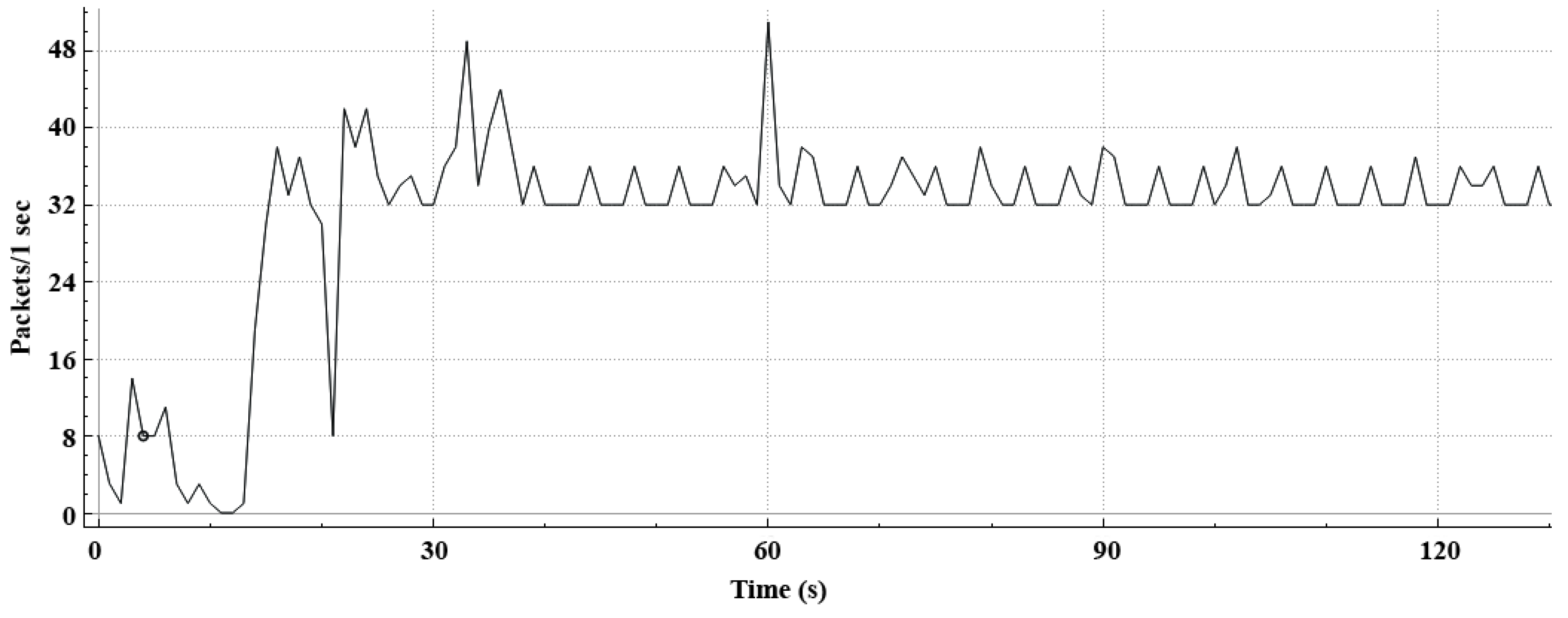
Scenario 3: In this third scenario, the OPC UA was started again before both industrial devices were connected to the network. However, in this case, unlike Scenario 2, both devices were executed at the same time. Figure 11 shows the behavior of the network traffic achieved in this case.
The results obtained of the network traffic in the third scenario are clearly coherent with respect to the previous results; that is, the increase in the network traffic depends directly on the number of the connected industrial devices discovered by the OPC UA server. However, we can observe some fluctuations in the traffic network at the initial stages of the auto-configuration of the OPC UA server, probably because the OPC UA server must share communication with both devices at the same time.
5. Conclusions and Future Works
The introduction of auto-configuration mechanisms in industrial environments without any human intervention is crucial for facilitating the development, deployment, and maintenance of any industrial system and, consequently, satisfying the increasing demands of Industry 4.0.
Although these mechanisms were applied mainly for industrial devices such as PLCs or RTU, we need to extend them to software systems that are part of the industrial ecosystem. Therefore, the extension to the rest of industrial software systems (not only on industrial automation) will contribute to establishing better support for current and future industry installations and will make the IIoT effective such as [39,40].
In this paper, the focus is on OPC UA systems that enable a secure data exchange between industrial devices and the software systems. The method proposed allows the automatic configuration and deployment of an OPC UA server only from the information provided by industrial devices. This gives OPC UA servers the ability to become first-class PnP systems and therefore improves the flexibility, adaptability, and scalability of the industrial system.
An OPC UA server with auto-configuration mechanism does not have to stop when a failure or production interruption is found. Thus, the operators can modify or substitute the faulty industrial devices or controller in production and the OPC UA server will automatically reconnect to the new ones by itself.
Hence, an OPC UA server can be adapted more easily to the modifications performed at the field layer, reducing the human errors derived from the system parametrization and the time needed to make the system operational. Consequently, this also reduces the costs of maintenance and deployment.
Author Contributions
These authors contributed equally to this work.
Funding
This work has been funded partially by the Software Engineering Department of the University of Granada.
Acknowledgments
We would like to acknowledge the participation of Dzmitry Basalai in this research paper for his helping in the elaboration of the prototype carried out in this work.
Conflicts of Interest
The authors declare no conflicts of interest.
References
- Vyatkin, V. Software Engineering in Industrial Automation: State-of-the-Art Review. IEEE Trans. Ind. Inform. 2013, 9, 1234–1249. [Google Scholar] [CrossRef]
- Lee, J.; Kao, H.A.; Yang, S. Service Innovation and Smart Analytics for Industry 4.0 and Big Data Environment. Procedia CIRP 2014, 16, 3–8. [Google Scholar] [CrossRef] [Green Version]
- Marcon, P.; Zezulka, F.; Vesely, I.; Szabo, Z.; Roubal, Z.; Sajdl, O.; Gescheidtova, E.; Dohnal, P. Communication technology for industry 4.0. In Proceedings of the 2017 Progress In Electromagnetics Research Symposium—Spring (PIERS), St. Petersburg, Russia, 22–25 May 2017; pp. 1694–1697. [Google Scholar]
- Sasajima, H.; Ishikuma, T.; Hayashi, H. Notice of Removal Future IIOT in process automation—Latest trends of standardization in industrial automation, IEC/TC65. In Proceedings of the 2015 54th Annual Conference of the Society of Instrument and Control Engineers of Japan (SICE), Hangzhou, China, 28–30 July 2015; pp. 963–967. [Google Scholar]
- Boyes, H.; Hallaq, B.; Cunningham, J.; Watson, T. The industrial internet of things (IIoT): An analysis framework. Comput. Ind. 2018, 101, 1–12. [Google Scholar] [CrossRef]
- Radziwon, A.; Bilberg, A.; Bogers, M.; Madsen, E.S. The Smart Factory: Exploring Adaptive and Flexible Manufacturing Solutions. Procedia Eng. 2014, 69, 1184–1190. [Google Scholar] [CrossRef] [Green Version]
- Lu, Y. Industry 4.0: A survey on technologies, applications and open research issues. J. Ind. Inf. Integr. 2017, 6, 1–10. [Google Scholar] [CrossRef]
- Dürkop, L.; Jasperneite, J. Plug and Produce als Anwendungsfall von Industrie 4.0. In Handbuch Industrie 4.0 Bd.2; Springer: Berlin/Heidelberg, Germany, 2016; pp. 59–71. [Google Scholar]
- Duerkop, L.; Trsek, H.; Jasperneite, J.; Wisniewski, L. Towards autoconfiguration of industrial automation systems: A case study using Profinet IO. In Proceedings of the 2012 IEEE 17th International Conference on Emerging Technologies Factory Automation (ETFA 2012), Krakow, Poland, 17–21 September 2012; pp. 1–8. [Google Scholar]
- Durkop, L.; Imtiaz, J.; Trsek, H. Service Oriented Architecture for the Autoconfiguration of Real Time Ethernet Systems. In Proceedings of the IEEE International Conference on Industrial Informatics (INDIN), Bochum, Germany, 29–31 July 2012. [Google Scholar]
- Durkop, L.; Imtiaz, J.; Trsek, H.; Wisniewski, L.; Jasperneite, J. Using OPC-UA for the autoconfiguration of real-time Ethernet systems. In Proceedings of the 2013 11th IEEE International Conference on Industrial Informatics (INDIN), Bochum, Germany, 29–31 July 2012; pp. 248–253. [Google Scholar]
- Hammerstingl, V.; Reinhart, G. Unified Plug&Produce architecture for automatic integration of field devices in industrial environments. In Proceedings of the 2015 IEEE International Conference on Industrial Technology (ICIT), Seville, Spain, 17–19 March 2015. [Google Scholar]
- Wilamowski, B.M.; Irwin, J.D. Industrial Communication Systems; Taylor & Francis Ltd.: Abingdon, UK, 2017. [Google Scholar]
- Imtiaz, J.; Jasperneite, J.; Weber, K.; Goetz, F.J.; Lessmann, G. A novel method for auto configuration of Realtime Ethernet Networks. In Proceedings of the 2008 IEEE International Conference on Emerging Technologies and Factory Automation, Hamburg, Germany, 15–18 September 2008; pp. 861–868. [Google Scholar]
- Dürkop, L.; Trsek, H.; Otto, J.; Jasperneite, J. A field level architecture for reconfigurable real-time automation systems. In Proceedings of the 2014 10th IEEE Workshop on Factory Communication Systems (WFCS 2014), Toulouse, France, 5–7 May 2014; pp. 1–10. [Google Scholar]
- Arai, T.; Aiyama, Y.; Maeda, Y.; Sugi, M.; Ota, J. Agile Assembly System by “Plug and Produce”. CIRP Ann. 2000, 49, 1–4. [Google Scholar] [CrossRef]
- Meng, Z.; Wu, Z.; Muvianto, C.; Gray, J. A Data-Oriented M2M Messaging Mechanism for Industrial IoT Applications. IEEE Internet Things J. 2017, 4, 236–246. [Google Scholar] [CrossRef]
- Cavalieri, S.; Stefano, D.D.; Salafia, M.G.; Scroppo, M.S. A web-based platform for OPC UA integration in IIoT environment. In Proceedings of the 2017 22nd IEEE International Conference on Emerging Technologies and Factory Automation (ETFA), Limassol, Cyprus, 12–15 September 2017; pp. 1–6. [Google Scholar]
- Ferrari, P.; Flammini, A.; Rinaldi, S.; Sisinni, E.; Maffei, D.; Malara, M. Impact of Quality of Service on Cloud Based Industrial IoT Applications with OPC UA. Electronics 2018, 7, 109. [Google Scholar] [CrossRef]
- Nakutis, Z.; Deksnys, V.; Jaruevicius, I.; Marcinkevicius, E.; Ronkainen, A.; Soumi, P.; Nikander, J.; Blaszczyk, T.; Andersen, B. Remote Agriculture Automation Using Wireless Link and IoT Gateway Infrastructure. In Proceedings of the 2015 26th International Workshop on Database and Expert Systems Applications (DEXA), Valencia, Spain, 1–4 September 2015; pp. 99–103. [Google Scholar]
- Civerchia, F.; Bocchino, S.; Salvadori, C.; Rossi, E.; Maggiani, L.; Petracca, M. Industrial Internet of Things monitoring solution for advanced predictive maintenance applications. J. Ind. Inf. Integr. 2017, 7, 4–12. [Google Scholar] [CrossRef]
- Reinhart, G.; Krug, S.; Huttner, S.; Mari, Z.; Riedelbauch, F.; Schlogel, M. Automatic configuration (Plug and Produce) of Industrial Ethernet networks. In Proceedings of the 2010 9th IEEE/IAS International Conference on Industry Applications—INDUSCON 2010, Sao Paulo, Brazil, 8–10 November 2010; pp. 1–6. [Google Scholar]
- Allard, J.; Chinta, V.; Gundala, S.; Richard, G.G. Jini meets UPnP: An architecture for Jini/UPnP interoperability. In Proceedings of the Symposium on Applications and the Internet, Orlando, FL, USA, 27–31 January; 2003; pp. 268–275. [Google Scholar]
- Ayatollahi, I.; Brier, J.; Mörzinger, B.; Heger, M.; Bleicher, F. SOA on Smart Manufacturing Utilities for Identification, Data Access and Control. Procedia CIRP 2018, 67, 162–166. [Google Scholar] [CrossRef]
- Virta, J.; Seilonen, I.; Tuomi, A.; Koskinen, K. SOA-Based integration for batch process management with OPC UA and ISA-88/95. In Proceedings of the 2010 IEEE 15th Conference on Emerging Technologies Factory Automation (ETFA 2010), Bilbao, Spain, 13–16 September 2010; pp. 1–8. [Google Scholar]
- Giret, A.; Garcia, E.; Botti, V. An engineering framework for Service-Oriented Intelligent Manufacturing Systems. Comput. Ind. 2016, 81, 116–127. [Google Scholar] [CrossRef]
- Rodríguez-Valenzuela, S.; Holgado-Terriza, J.; Gutiérrez-Guerrero, J.; Muros-Cobos, J. Distributed Service Based Approach for Sensor Data Fusion in IoT Environments. Sensors 2014, 14, 19200–19228. [Google Scholar] [CrossRef] [PubMed]
- Jammes, F.; Smit, H. Service-Oriented Paradigms in Industrial Automation. IEEE Trans. Ind. Inform. 2005, 1, 62–70. [Google Scholar] [CrossRef]
- Jammes, F.; Mensch, A.; Smit, H. Service-Oriented Device Communications Using the Devices Profile for Web services. In Proceedings of the 21st International Conference on Advanced Information Networking and Applications Workshops, Niagara Falls, ON, Canada, 21–23 May 2007; pp. 947–955. [Google Scholar]
- OASIS. Web Services Dynamic Discovery (WS-Discovery) Version 1.1. Available online: http://docs.oasis-open.org/ws-dd/discovery/1.1/os/wsdd-discovery-1.1-spec-os.html (accessed on 14 January 2019).
- Shinde, G.; Olesen, H. A Survey on Service Discovery Mechanism. In Intelligent Computing and Information and Communication; Springer: Singapore, 2018; pp. 227–236. [Google Scholar]
- Shimanuki, Y. OLE for process control (OPC) for new industrial automation systems. In Proceedings of the IEEE International Conference on Systems, Man, and Cybernetics (Cat. No.99CH37028), Tokyo, Japan, 12–15 October 1999; Volume 6, pp. 1048–1050. [Google Scholar]
- Damm, M.; Leitner, S.H.; Mahnke, W. OPC Unified Architecture; Springer: Berlin/Heidelberg, Germany, 2009. [Google Scholar]
- Modbus Messaging on TCP/IP Implementation Guide V1.0b; Modbus Organization Inc.: Hopkinton, MA, USA, 2006.
- Industrialshields. M-DUINO. Available online: https://www.industrialshields.com/ (accessed on 19 June 2018).
- Arduino. Ardino Manufactuer Web Site. Available online: https://www.arduino.cc/ (accessed on 18 February 2019).
- Barbosa, A.S. Modbus C++ Base Library. Available online: https://github.com/andresarmento/modbus (accessed on 23 January 2018).
- Prosys. OPC UA Client. Available online: https://www.prosysopc.com/products/opc-ua-client/ (accessed on 10 September 2018).
- Mumtaz, S.; Alsohaily, A.; Pang, Z.; Rayes, A.; Tsang, K.F.; Rodriguez, J. Massive Internet of Things for Industrial Applications: Addressing Wireless IIoT Connectivity Challenges and Ecosystem Fragmentation. IEEE Ind. Electron. Mag. 2017, 11, 28–33. [Google Scholar] [CrossRef]
- Nuratch, S. The IIoT devices to cloud gateway design and implementation based on microcontroller for real-time monitoring and control in automation systems. In Proceedings of the 2017 12th IEEE Conference on Industrial Electronics and Applications (ICIEA), Siem Reap, Cambodia, 18–20 June 2017; pp. 919–923. [Google Scholar]
Figure 1.
An OPC UA server can manage the information models for each industrial device.

Figure 2.
Architecture of the industrial system for the auto-configuration of OPC UA.

Figure 3.
Message exchange between the OPC UA server and an industrial device during the auto-configuration of OPC UA server in TCP/IP mode and the subsequent periodic requests/responses in Modbus mode.
Figure 3.
Message exchange between the OPC UA server and an industrial device during the auto-configuration of OPC UA server in TCP/IP mode and the subsequent periodic requests/responses in Modbus mode.

Figure 4.
Schematic of the information exchange between the PLC device and OPC UA server once the auto-configuration of OPC UA is finished.
Figure 4.
Schematic of the information exchange between the PLC device and OPC UA server once the auto-configuration of OPC UA is finished.

Figure 5.
Architecture of the system prepared for the case study that includes the OPC UA server, the OPC UA client, the M-DUINO PLC and the Arduino ONE.
Figure 5.
Architecture of the system prepared for the case study that includes the OPC UA server, the OPC UA client, the M-DUINO PLC and the Arduino ONE.

Figure 6.
A view of the hardware devices managed in the case study.

Figure 7.
A screenshot of the graphic program in Java deployed on the OPC UA server for this work that shows a panel with the configuration of two PLC devices.
Figure 7.
A screenshot of the graphic program in Java deployed on the OPC UA server for this work that shows a panel with the configuration of two PLC devices.

Figure 8.
A screenshot of the Prosys OPC UA client accessing the information model of OPC UA.

Figure 9.
The graph includes the network traffic generated between the M-DUINO and the OPC UA server.
Figure 9.
The graph includes the network traffic generated between the M-DUINO and the OPC UA server.

Figure 10.
The graph includes the network traffic generated between two devices (M-DUINO and Arduino ONE) and the OPC UA server.
Figure 10.
The graph includes the network traffic generated between two devices (M-DUINO and Arduino ONE) and the OPC UA server.

Figure 11.
The graph includes the network traffic generated between two devices (M-DUINO and Arduino ONE) and the OPC UA sever connected at the same time.
Figure 11.
The graph includes the network traffic generated between two devices (M-DUINO and Arduino ONE) and the OPC UA sever connected at the same time.

© 2019 by the authors. Licensee MDPI, Basel, Switzerland. This article is an open access article distributed under the terms and conditions of the Creative Commons Attribution (CC BY) license (http://creativecommons.org/licenses/by/4.0/).
Share and Cite
MDPI and ACS Style
Gutierrez-Guerrero, J.M.; Holgado-Terriza, J.A. Automatic Configuration of OPC UA for Industrial Internet of Things Environments. Electronics 2019, 8, 600. https://doi.org/10.3390/electronics8060600
AMA Style
Gutierrez-Guerrero JM, Holgado-Terriza JA. Automatic Configuration of OPC UA for Industrial Internet of Things Environments. Electronics. 2019; 8(6):600. https://doi.org/10.3390/electronics8060600
Chicago/Turabian StyleGutierrez-Guerrero, Jose Miguel, and Juan Antonio Holgado-Terriza. 2019. "Automatic Configuration of OPC UA for Industrial Internet of Things Environments" Electronics 8, no. 6: 600. https://doi.org/10.3390/electronics8060600
Note that from the first issue of 2016, this journal uses article numbers instead of page numbers. See further details here.