Analysis and Design of Functional Device for Vehicular Cloud Computing


1
Jiangsu Provincial Engineering Laboratory of Pattern Recognition and Computational Intelligence, Jiangnan University, Wuxi 214122, China
2
Jiangsu Key Construction Laboratory of IoT Application Technology, Taihu University of Wuxi, Wuxi 214122, China
3
China North Vehicle Research Institute, Beijing 100084, China
*
Author to whom correspondence should be addressed.
†
Current address: School of Internet of Things Engineering, Jiangnan University, Wuxi 214128, China.
Electronics 2019, 8(5), 583; https://doi.org/10.3390/electronics8050583
Submission received: 24 April 2019
/
Revised: 21 May 2019
/
Accepted: 21 May 2019
/
Published: 26 May 2019
(This article belongs to the Special Issue Vehicular Networks and Communications)
Abstract
:Relay technology application becomes prevalent nowadays, as it can effectively extend the communication distance, especially for vehicular networks with a limited communication range. Combined with vehicular cloud (VC), transmission efficiency can be improved by offloading partial data. Hence, designing a vehicle relay algorithm and implementation embedded vehicle device is critical. In this paper, VC is considered to deal with the complexity computation in our proposed system model. Without a loss of generality, an end-to-end vehicle communication with one assisted vehicle is analyzed firstly on a transmission link based on VC. Here, the signal-to-noise ratio (SNR) on the receiving end and link outage probability is obtained to enhance the link reliability. The VC computing helps us further simplify computational complexity. Subsequently, an embedded vehicle-enabled device is designed to achieve the optimal path relay selection in realistic vehicular environments. In the functional device framework, we display an optimal path relay selection algorithm according to the link quality. Finally, the performance of the transmission link on the outage probability related with SNR is verified in the simulation results. Meanwhile, the effect of the relay gain is also analyzed. The application of a vehicle-enabled embedded device could improve the performance of vehicular networks.
1. Introduction
Vehicular ad hoc networks (VANETs) are a special mobile ad hoc network for implementing various road traffic applications [1]. It can improve the future development of the transportation system via wireless communication technologies, such as advanced information processing, wireless communication, and device-to-device communication [2,3]. The highly dynamic topological changes on the network structure and multiple service requirements of users bring significant challenges for VANET applications.
As we all know, safety message transmissions are critical to ensure road traffic safety in vehicular networks. IEEE standards 802.11p [4] and 1609.4 [5] were developed to ensure reliable communication in the highly dynamic propagation environment of vehicular networks. The original IEEE 802.11p standard was based on a media access control (MAC) sublayer that showed poor performances in provisioning the quality of service (QoS) for different applications in dense VANETs [6,7]. These problems were particularly important for the reliable transmission of safety messages. Therefore, the multichannel extension IEEE 1609.4 standard was proposed to improve the imperfection in the IEEE802.11p standard.
In suburban environments, there are spare infrastructures and few vehicles, which is why cooperative relay technologies have been proposed recently as an efficient solution to cope with the many challenges in VANETs [8,9,10,11]. In vehicular networks, road-safety warnings, road-condition reports, and other safety messages are critical for ensuring road traffic safety. To employ a rational use of networks resources, cooperation can be employed to help users take advantage of the broadcast nature of radio frequency transmissions. In this paper, we consider the two-hop transmission case between the source vehicle and destination vehicle. It is possible that there is not a direct link between the source vehicle and destination vehicle. When a source vehicle communicates with a destination vehicle via another vehicle acting as a relay-assisted role, a two-hop vehicular system is formed. We will analyze these two-hop vehicular networks in performance and further realize it in following works.
Specifically, we study the end-to-end vehicle communication in obeying Dedicated Short Range Communications (DSRC). The assisted vehicle can be introduced to relay transmission messages between two end-to-end vehicles. Then, we analyze the performance of assisted vehicles on a transmission link based on VC. In addition, an optimal path relay selection algorithm is proposed and applied to design an embedded vehicle-enabled device. The major contributions of this paper are as follows:
- Employs a novel graph model to model a vehicle-to-vehicle communication scenario which deploys respectively in a two adjacent Roadside Units (RSUs) area.
- Analyzes link outage probability and gives out expresses depending on SNR in receiving end in end-to-end communication.
- Designs a functional device for vehicular cloud computing to realize a relay-assisted scheme for vehicular application.
- Proposes an optimal path relay selection algorithm to cope with the vehicle transmission problem which is beyond the transmission range.
The rest of this paper is organized as follows. Some related works are introduced in Section 2. Section 3 provides the system model of amplify-and-forward (AF) relay-assisted vehicular networks. Based on the Section 3, Section 4 discusses the specific performance analysis on the probability of an outage with a directing communication channel and relay-assisted communication channel. Whereafter, a relay-assisted scheme for vehicular networks is proposed in Section 5. In Section 6, the simulation results reveal that the relationship between the outage probability and the SNR are evaluated to confirm the suitability of the proposed relay-assisted scheme. Finally, Section 7 summarizes and concludes this paper.
2. Related Works
Recently, many works have been researched on relay selection applications due to its advantages in vehicular networks [12,13,14,15]. Reference [12] proposed a power allocation and relay selection scheme limited by outage probability to increase the performance of vehicular networks. Reference [13] reported on cooperative diversity with relay selection over cascaded Rayleigh fading channels in dual-hop decode-and-forward (DF) vehicular networks. Reference [14] proposed the optimal relay scheme by considering the vehicle location and link capacity in vehicular networks. However, these relay schemes also brought complicated data frame communication process and computing on performance analysis. The cooperative communication tailored as vehicular cooperative media access control (VC-MAC) is designed in Reference [15] to maximize the system capacity. The current results are within the limits of congestion control issues, the Rayleigh fading channel assumption, the maximum end-to-end capacity, and cooperation downloads for vehicular networks. Experimental and theoretical studies have researched appropriate fading models under the condition of a Rayleigh fading channel for inter-vehicular channels.
In cascaded rayleigh fading, the performance of relaying for vehicular cooperative strategy assisted by a RSU or relay which acts as relay is investigated [16]. It carried out a further comprehensive analysis based on Reference [17] which only considers RSUs which act as relays. Reference [18] proposed a vehicle-to-vehicle communication protocol for cooperative collision warnings. However, they mainly consider a low latency when delivering emergency warnings in various road situations. The QoS of vehicular networks, which considers the possibility of an outage during emergency warnings communication, is not considered. To improve QoS, decentralized relay-assisted multiuser multiple-input multiple-output (MIMO) approaches are widely used in References [19,20,21,22]. Reference [23] mainly studied the promising effects of cooperative transmissions in radio frequency communications. The two-transmitter case was considered, but it did not consider the direct transmission case between the source vehicle and destination vehicle. The introduction of vehicular cloud computing has promoted the development of related vehicular technologies [24,25]. In Reference [26], two opportunistic relay selection algorithms were proposed and the results showed that the selected relay had an impact on the interference generated in the network and the stability of the relay. To minimize these interference, the authors proposed a suitable relay selection scheme [27]. These works also did not consider the complicated calculations and transmission delay caused by the analysis.
Real-time data transmission response was the key feature of DSRC in a rapidly changing environment. Data dissemination was one of most critical issues for vehicular traffic environments [28]. These real-time data applications required complex computations and brought challenges in implementing applications for vehicle devices [29,30]. Recently, many researches adopted clod computing to address these challenges for vehicle devices. Reference [31] proposed a geocast routing protocol for the reliable and efficient dissemination of data due to an increase in vehicular applications favoring geocasting. Reference [32] designed a beaconless packet forwarding protocol by considering the vehicle direction and link quality during packet transmission. However, these protocols suffered from higher end-to-end delays in vehicular networks.
3. System Model
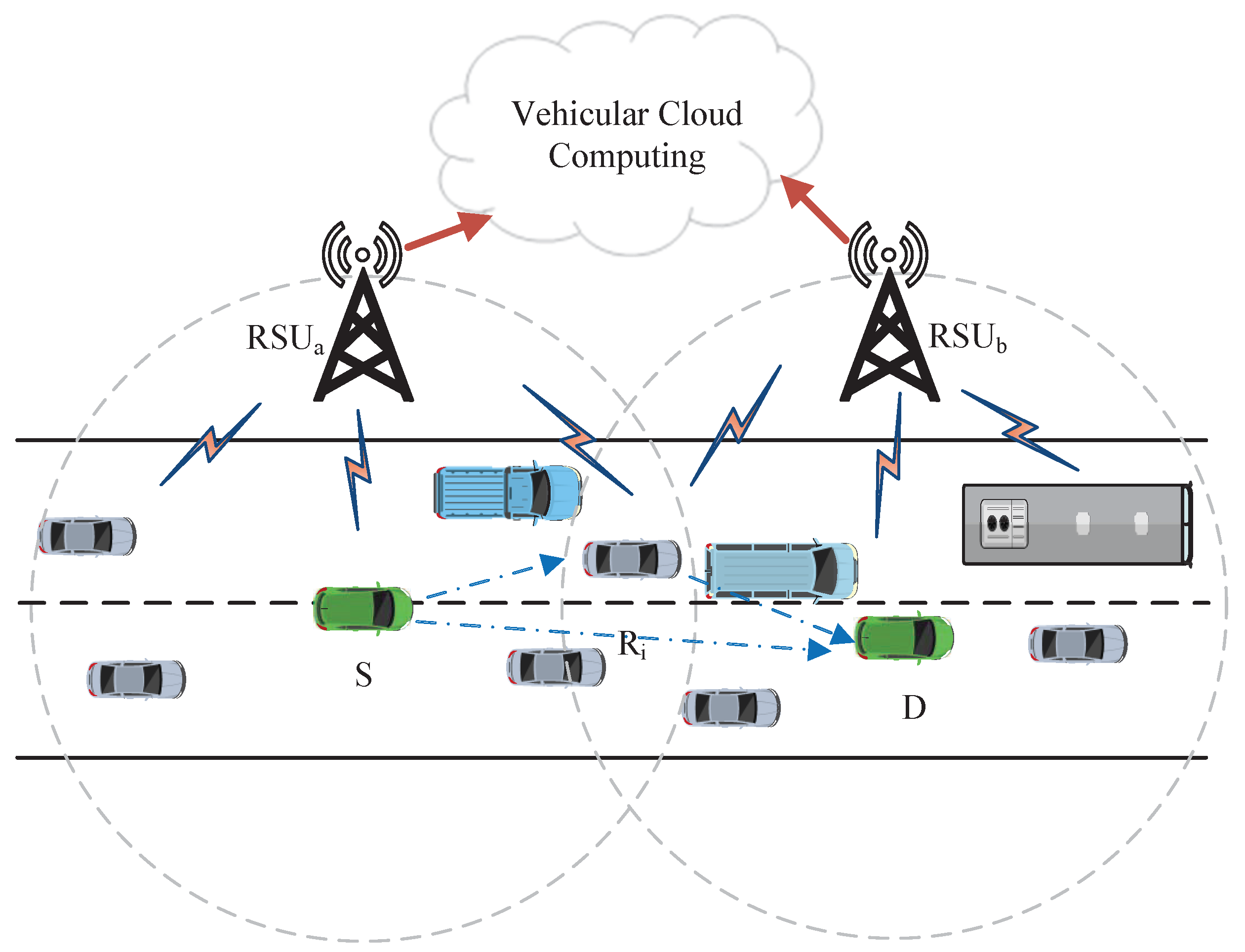
The main reliable wireless technologies implementation of the vehicular networks is DSRC. Due to vehicle mobility and network topology changes, communication between vehicles is sometimes not possible by direct transmission according to DSRC. We focus on a two adjacent RSUs and vehicles scenario where vehicle S attempts to transmit a message to vehicle D, as shown in Figure 1. The road is a two-lane unidirectional road, and RSUs (such as and ) are deployed along the road. Vehicles on the road have uninterrupted traffic in a free flow state. When communicating between the source vehicle S and the destination vehicle D, we assume they are in two adjacent different areas. DSRC provides two communication modes in the networks: Vehicle-to-Infrastructure (V2I) communication and Vehicle-to-Vehicle (V2V) communication. Cloud-based services and vehicular networks are combined to form a VC. It provides powerful computing power, also known as vehicular cloud computing. Some complex calculations can depend on VC to realize the computation in this V2I transmission mode, and the V2V transmission mode ensures a transmission between the source vehicle and destination vehicle.
3.1. V2I Communication
All vehicles communications in vehicular networks can be regard as a VC for processing some complicated service applications. In addition, all vehicles can upload data to the VCs through RSUs in their respective region. Meanwhile, each RSU also provides wireless access services within its communication range for the vehicles. For complex service applications and computation, vehicles transmit their data to RSUs by a V2I communication mode as of limited computation resource. Based on the V2I communication mode, the vehicle can only access the corresponding RSU located on the road when it runs within a given segment.
The communication between the adjacent RSUs through wireless backhauls. The RSUs establish a communication connection with the VCs. Vehicles within the communication range of each RSU cannot transmit the received data to the other RSU. In other words, the vehicle in the coverage area of cannot communicate with directly. The same applies to vehicles in the coverage area of . The vehicle cloud formed by all vehicles in networks can communicate with any device in the entire network. This communication mechanism can improve the transmission efficiency of wireless backhauls. Vehicles also receive data/commands from the corresponding RSU for VC.
3.2. V2V Communication
In vehicular networks, both the vehicles and RSUs have short range communications due to their DSRC devices. In addition, a vehicle runs on a road with a steady speed, and the traffic in terms of vehicles remains stable. When one vehicle within the coverage range attempts to transmit messages to another vehicle within the coverage range, a V2V communication link is required to forward messages through one relay vehicle (such as , , where N is the total number of candidate relay nodes). The system model is shown in Figure 1.
In a Rayleigh-fading work scenario, a moving vehicle S has critical messages to transmit to a moving vehicle D. Each vehicle is equipped with a GPS device. Hence, the position coordinates are known. The maximum communication range for every vehicle is fixation , and the distance between vehicle S and vehicle D is denoted as , which is
where and are the respective coordinates of vehicle S and vehicle D.
When vehicle S attempts to establish a communication link with vehicle D, there are two cases: direct communication and indirect communication. One case happens at and the other case happens at , where is the maximum communication range of one vehicle. We assume that vehicle S attempts to transmit a signal , which has an average power , to vehicle D.
3.2.1. Direct Communication
For the case of direct communication, the vehicle D receives a signal from vehicle S via a wireless channel. The receiving signal is written as
where is an channel coefficient and is an additive white Gaussian noise (AWGN) term with a one-sided power spectral density (PSD) .
The SNR related to a direct communication link at the receiving end can be calculated as
3.2.2. Indirect Communication
For the case of indirect communication, the candidate vehicle set is adopted in this case, and the which occurs between vehicle S and vehicle D is essential. The vehicle S transmits a signal to vehicle D, which is beyond the communication range, with the help of one assisted vehicle belonging to . Suppose the established links are independent of each other.
Similarly, we assume that vehicle S is transmitting a signal to vehicle D via one relay-assisted vehicle that is within the set. The received signal by one relay vehicle which is in is given by
where is an channel coefficient and is an AWGN term with a one-sided PSD . The term exists in the first hop channel.
When the signal is received by one relay vehicle, which is in , it will be processed (Obeying Amplify-and-Forward (AF) protocol) by gaining modulation A. Then, the processed signal is transmitted to the destination vehicle via a relay channel that is between and D. The received signal at terminal D can be expressed as
where is an channel coefficients and is an AWGN with a one-sided PSD . The term is in the second-hop channel. According to Equation (5), the overall SNR at the receiving terminal can be written as
Under certain environmental or channel correlation coefficients, we can infer from Equation (6) that the choice of AF relay gain A is equivalent to the SNR for two-hop channels. The AF relay gain A is thus given by Reference [33]
where is the power of the relay node, and we assume all vehicles have the same power in this paper, that is .
As a short hand notation, we use the notations and to denote the SNRs of the per hop channel. The instantaneous SNR of a two-hop channel is
where and are the average SNRs of the two channels respectively. The notation denotes that y is exponentially distributed with parameter x.
The form of the equivalent SNR in Equation (9) is not easily tractable with our approach. This is due to the complexity in finding the statistics (i.e., the Probability Density Function (PDF), Cumulative Distribution Function (CDF), and Moment Generation Function (MGF)) associated with it. The fading parameter of the first link is low. The choice of the above gain aims to limit the output power of the vehicle (relay) .
At a higher SNR, the constant 1 in the denominator of Equation (9) can be omitted. Fortunately, this treatment can be tightly bounded. As a result, Equation (9) can be approximated by
In Equation (10), the fading parameter of the channel, , is high. This implies that the relay choice gain A in Equation (7) can omit the noise, , and can be re-written as
To get the PDF of , we need to recall the definition of the harmonic mean and of an exponential variation in Reference [34,35]. We notice that
where is defined as the reciprocal of the arithmetic mean of the reciprocals of channel and .
4. Performance of Two-Hop Relay-Assisted Vehicular Networks
In terms of mobility and the changing topology of vehicular networks, we need to ensure that safety messages will be transmitted with a high quality and timeliness. In this case, we assume that the end-to-end transmission rate is R. As we know, the channel capacity is a measure of the maximum channel capacity to transmit information.
4.1. Link
For wireless vehicular networks, the mutual information capacity of the link channel could be easy to achieve from Equation (3) via the Shannon theory,
The outage probability is defined as the probability of event that the instantaneous channel capacity falls below this desired rate R, namely
There have been a lot of research works in this direct communication case. Therefore, this work mainly focuses on the following link case.
4.2. Link
The capacity of the link can be inferred using the Shannon theory and in combination with Equation (9). The capacity of this link is denoted as ,
To ensure QoS, the SNR threshold is defined, and it essentially depends on the modulation type. In this case, the outage probability of the link is defined as the probability with an instantaneous SNR, , that falls below a protection threshold, namely [34]
Here, is given by
Substituting Equation (14) into Equation (13) leads to the approximate expression in Equation (13) for the case in Equation (10), which is given by
where is a first-order modified Bessel function of the second kind. Therefore, from the above context and Equation (8), we see that the distribution of the approximated expression of in Equation (15) is given as follows [35]:
This complex operation can be handled at VC for reducing communication loads on a vehicle. Although the introduction of VC technology has increased the computing power for the vehicular networks, complex calculations will increase the time consumption of a VC computing process [36]. This will increase the safety messages transmission delay. Therefore, further computational simplification is necessary.
When [37], at a higher SNR. Hence, we can utilize the property to re-calculate the outage probability in Equation (22) as
By utilizing the first-order Taylor formula approximation about the exponential function, we can approximate the expression in Equation (23) further as
Equation (24) for the outage probability, in addition to being an approximate formula for the choice of destination SNR in Equation (10), is also a simple lower bound for AF relay-assisted vehicular networks. To benefit the device deployment, the process also reduces the computational complexity of the equipment.
5. Design of Relay-Assisted Scheme for Vehicular Application
5.1. Embedded Device Design
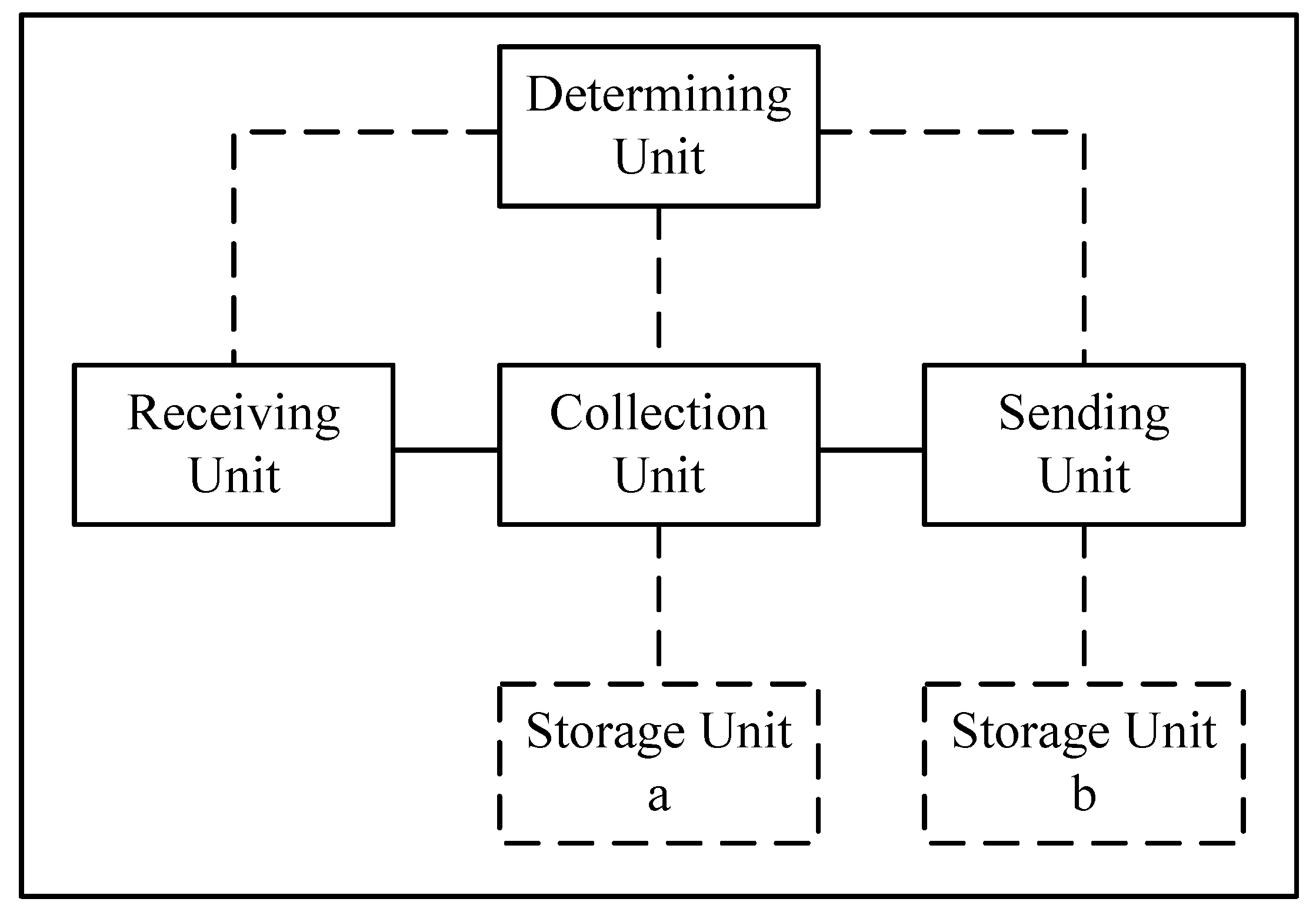
The designed function module diagram of the vehicular device is illustrated in Figure 2 and based on Reference [38]. This embedded function device includes the following five modules: Receiving Unit, Collection Unit, Determining Unit, Sending Unit, and Storage Unit. Various Units work compatibly with one another. The Collection Unit, Determining Unit, and Storage Unit can be implemented by one or more processors. Additionally, the Receiving Unit and Sending Unit can be implemented by the antenna, filter, modulator-demodulator, and coder-decoder.
In this device, the modules cooperate with one another. The functions of each part of this relay-assisted device are described as follows:
Receiving Unit: Can be configured to receive relay-assisted setup requests from a source communication device.
Collection Unit: Can be configured to respond to channel information collecting requests and to collect two-hop channel SNRs.
Determining Unit: Can be configured to receive SNRs from all candidate relay-assisted communication devices and to determine if one or more relay-assisted communication devices are needed.
Sending Unit: Can be configured to transfer a relay-assisted setup request to and from a source communication device, one or more relay-assisted communication devices, and a destination device.
Storage Unit: Can be configured to save the acquired SNRs and relative tags of all candidate relay-assisted communication devices.
This device can be placed in the control device of vehicular networks, and it is not limited to this placement. In summary, this device can be placed in any vehicle that is part of the vehicular networks. Source vehicle S can transfer messages to the destination vehicle D via relay-assisted vehicles . Figure 1 illustrates this vehicular networks scenario.
Source vehicle S can send a relay setup request and/or channel information collection requests to the designed device. The Receiving Unit of this designed device receives the requests. Then, the Collection Unit of this designed device detects the channel information from where it is. Subsequently, the Determining Unit of this designed device achieves the SNRs, and , for each candidate vehicle and selects one candidate vehicle as the relay-assisted vehicle on the basis of this information to communicate with destination vehicle D. The and are obtained from the VC. We note that the Determining Unit can also be configured to be a Storage Unit. This way, the system can further reduce the amount of information requiring an exchange between the candidate communication devices and the designed device that can improve the network’s efficiency. Finally, the Sending Unit sends the relay setup information mark, which has been designated to carry out the communication process to the source vehicle, selected relay vehicle, and destination vehicle. Storage Unit b must also save this information to reduce the processing time and to improve the network efficiency.
To the best of my knowledge, some mentioned embodiments of this designed device can be implemented by partially or fully using hardware and/or firmware. Therefore, this device can be widely used in vehicular networks in the future.
5.2. Optimal Path Selection Algorithm
With topological changes and high speed vehicles joining vehicular networks, especially on freeways, vehicular networks have many additional technical challenges, such as great channel fading and poorly received signal quality. Cooperation-based communication technologies can take advantage of wireless terminal devices to establish multiple communication links when sending and receiving information that can overcome fading radio channels via conventional multi-antenna spatial diversity techniques and by improving wireless network system performance and robustness. This way of selecting relay-assisted vehicles could achieve a higher functionality when communication links are dynamically selected. Furthermore, the vehicular network communication efficiency can be improved by this process.
Here, one vehicle communicates with another vehicle via a relay-assisted vehicle when zero-forcing (ZF) detectors [33] are employed to receive the messages and suppress interference. This type of relay technique is leveraged in this paper, which is an industrial communication solution for long-distance, cooperative connectivity [13]. For high-speed vehicular networks, Reference [39] proposed a scheme to provide a full-duplex relaying connectivity for an unstable direct link and imprecise channel state information (CSI). Reference [40] also cites out the effect of outdated channel state information on the outage and error rate performance of AF relay selection, where only one out of the set of available relays is selected.
Relay techniques are further exploited in this paper. These techniques have been an industrial communication solution for long-distance transmission. The basic system model is illustrated in Figure 1.
From Equation (10), we need to know at the ith path. Apparently, this random formula accounts for the channel gain of both and links. The total SNR set via the ith path is defined as
Theoretically, we know that the designed device can be theoretically put into any device in the vehicular networks, as described in Section 5.1. In this paper, we assume that the designed device is embedded in the source vehicle. On the other hand, we assume that the source vehicle could get all outdated CSI from the set of relays. When the source vehicle receives packets, which include , the destination will analyze this set and select the “best” relay-assisted vehicle , expressed as
The presence of an optimal path selection operation within a vehicle device in two-hop vehicular networks is identified by Algorithm 1. This algorithm is executed in the VC, and the execution results are notified by the VC to all vehicles in the vehicular networks via an RSU. All vehicles transmit their own information and related channel information to the cloud. After a series of processing as in Section 5.1, the cloud feeds the final result back to all vehicles in vehicular networks to help the source vehicle discover the assisted vehicle.
When the source vehicle S requires the assisted vehicle to relay information to the destination vehicle D, it is easy to see from Algorithm 1 that all vehicles upload their own information and channel information to the VC. The VC uses its computing power to compute the SNR of each link between vehicles according to our analysis in Section 4. Then, the VC downloads the final results to all vehicles in the vehicular networks. The source vehicle S could select an optimal vehicle as an assisted vehicle to transmit information to the destination vehicle D according the received information from the VC.
| Algorithm 1 The optimal path relay selection based on the vehicular cloud (VC). |
|
6. Simulation Results
In this section, we use a rigorous mathematical analysis to discuss the performance of vehicular networks. The experimental results evaluate the performance of vehicular networks for an outage probability based on the designed relay-assisted selection scheme by using MATLAB tools. As directing the transmission between S and D is a simply wireless communication link from Section 4.1 and has many experimental results, we cannot do the experiments again in this work. The simulation scenario mainly considers a two-hop relay vehicular network where a vehicle can transmit messages to other vehicles via a relay vehicle. According to Section 5.1, vehicles could collect SNR information which is embedded in the packet header from the upper vehicles in the device.
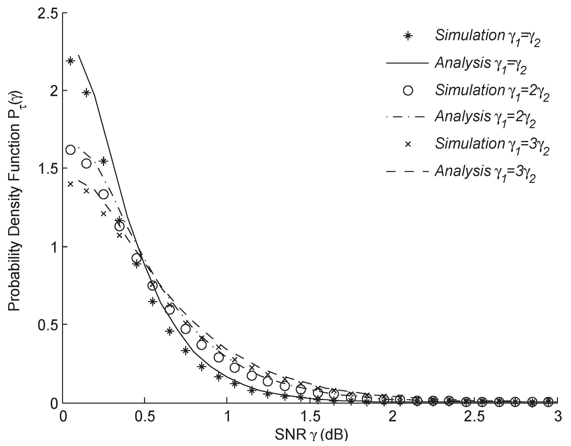
To verify the performance of the system, a Monte Carlo simulation (1000 times) is adopted via MATLAB toolboxes. Subsequently, the PDF in Equation (15) is illustrated in Figure 3. The analytical results are an excellent match to the simulation results for the cases where , , and . With the growth of , the outage probability of gradually decreases until it reaches 0. Before , the outage probability of gradually increases from the bottom (diamond line) to the top (star line). After , we get opposite results from before .
Based on the analysis of Section 3, we know the instantaneous SNR depends on the gain A. When the gain A is , the instantaneous SNR is equivalent to Equation (9). Hereafter, we get the approximated instantaneous SNR Equation (10). In this situation, the gain A is . The various SNRs have some effects on the outage probability of vehicular networks. In vehicular networks, a vehicle-assisted network adopts the AF protocol. The gain’s influence on the relay system is shown in Figure 4.
Equation (7) helps us get a tight lower bound for an AF system instead of being an exact formula for the choice of relay gain in Equation (11). From the analysis of Section 3, we know the instantaneous SNR is dependent on the gain A. The different SNRs have some effects on the outage probability of vehicular networks. Figure 4 plots the types of relay gain effects on relay systems. We can see from the figure that the two curves are essentially indistinguishable for all practical purposes with the growth of SNR. Thus, the outage probability is essentially indistinguishable according to the two curves, especially at higher SNRs.
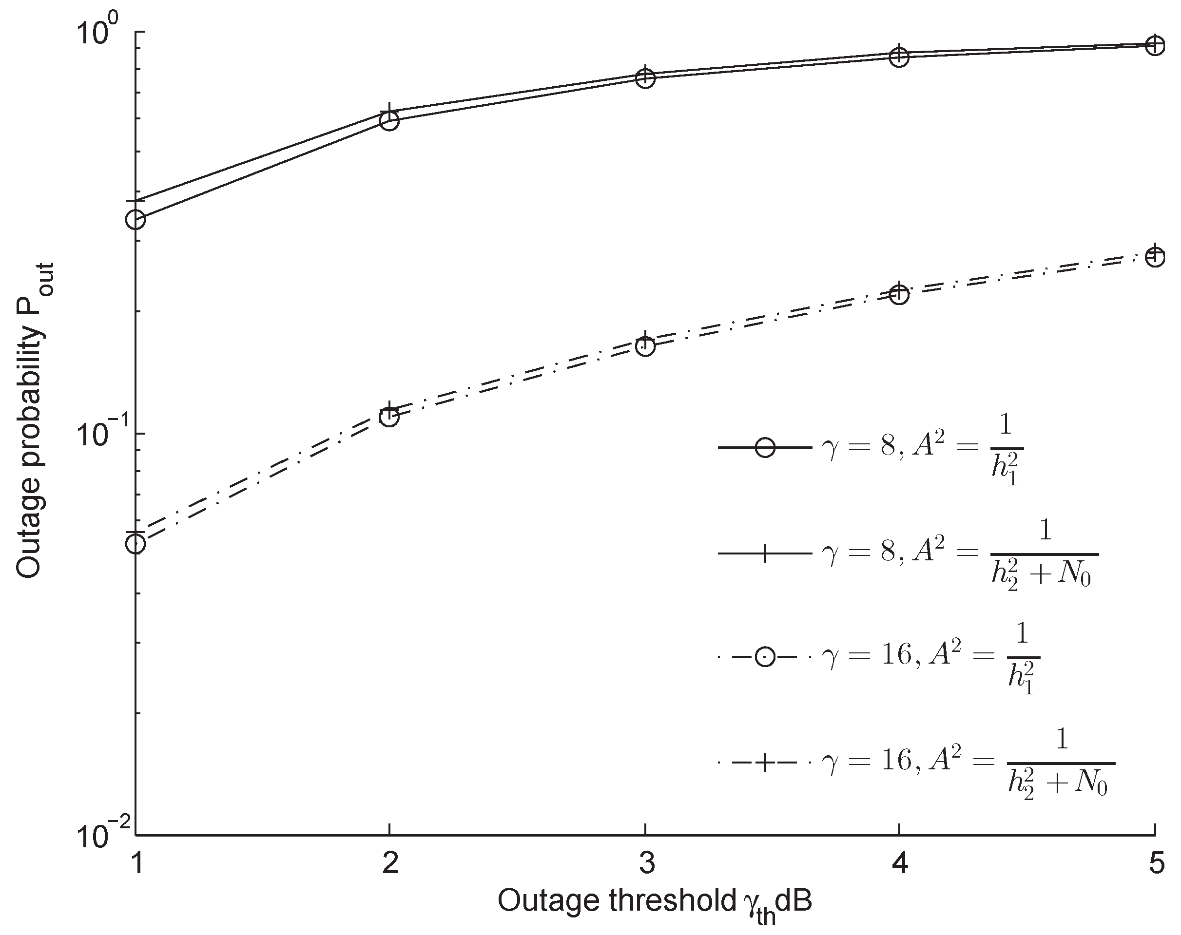
The variation of the outage probability with at different AF relay A gains has been studied for setting an outage threshold . The results of the outage probability versus outage threshold are shown in Figure 5 for different values of . We can see that the higher SNR reduces the outage probability in all AF relay gain cases. Moreover, it is clear that, for the same case, the two curves are essentially indistinguishable.
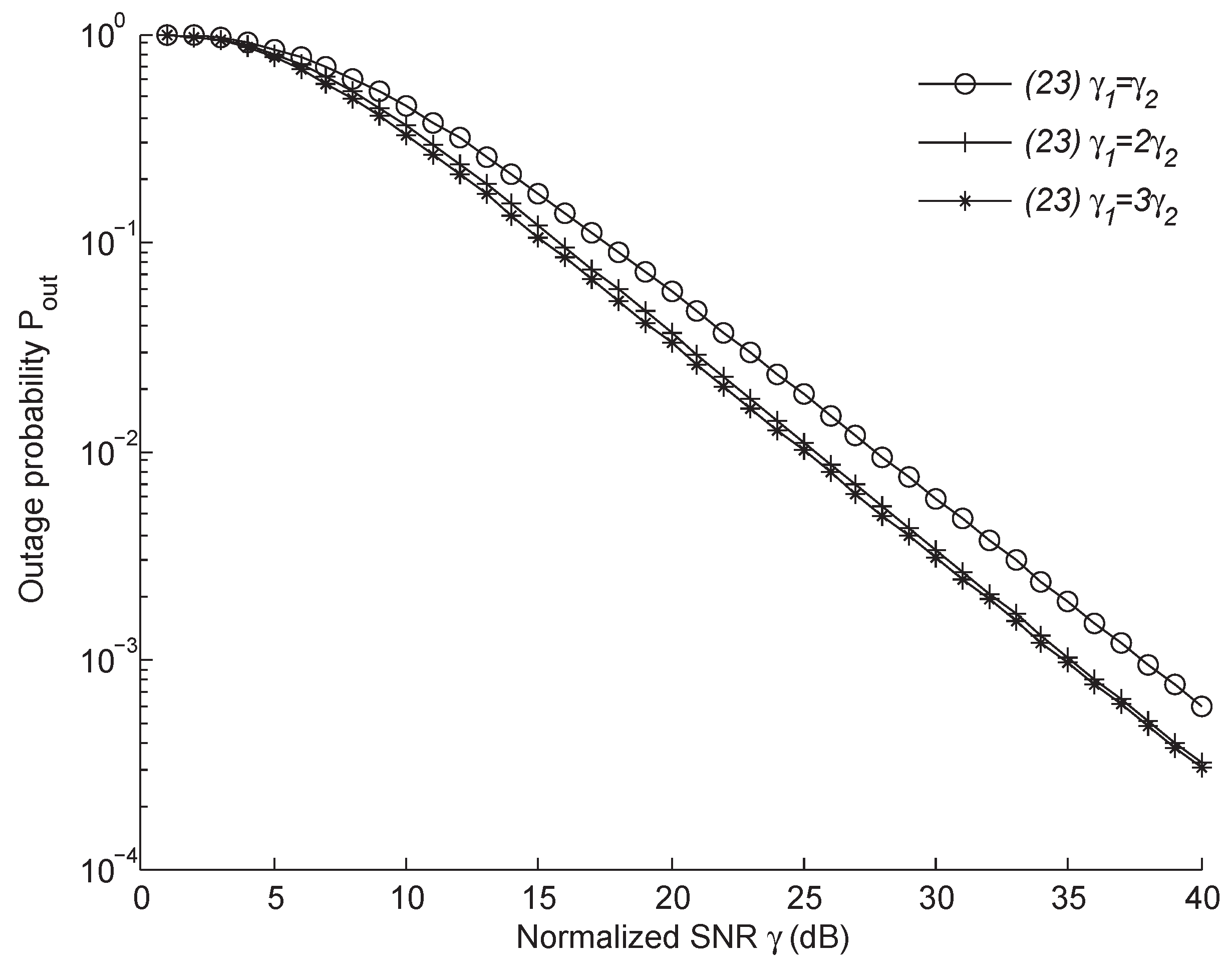
During the process of deriving the final outage probability, we obtained some intermediate results, such as Equations (22) and (23). These results can help us better evaluate the performance of vehicular networks. Figure 6 compares the performance of AF relay-assisted vehicles for the cases where , , and in terms of Equation (22). With the growth of SNR , the outage probability gradually decreases to 0. At a lower SNR, the outage probability varies slowly until a sharp decline at dB. On the other hand, the outage probability is essentially indistinguishable with the growth of when compared with from the SNR dB.
In comparison with Equation (22), Equation (23) provides more accurate approximate results at a higher SNR via the handling function . The outage probability numerical results are shown in Figure 7. It shows almost the same curve trend as that shown in Figure 6, except there is a subtle difference in the case of , , and . At a lower SNR, the outage probability varies slowly until it sharply declines at dB.
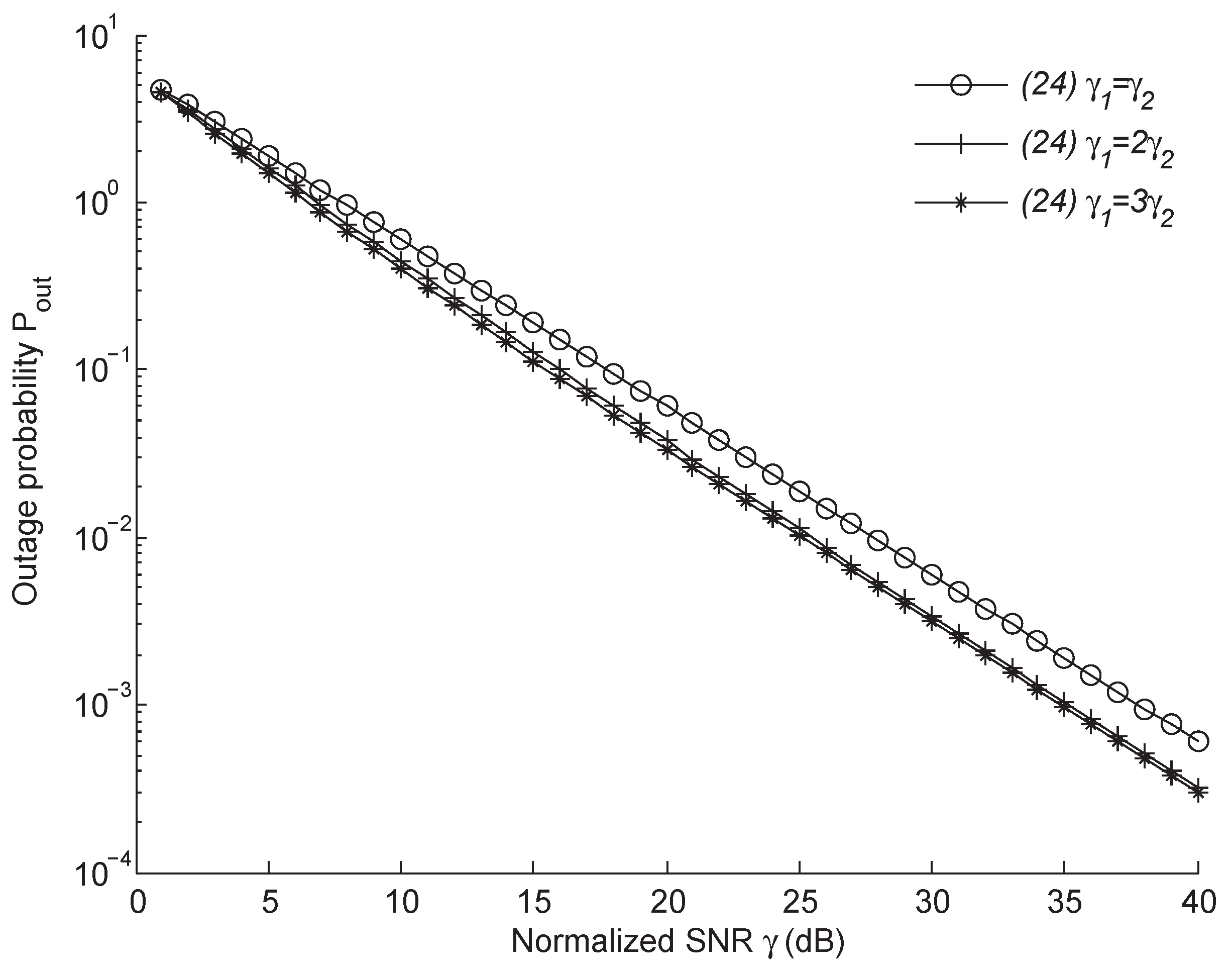
Figure 8 shows the outage probability of AF relay-assisted vehicular networks based on the Taylor expansion . The result of Equation (24) greatly reduces the complexity of the outage probability . In Figure 8, the outage probability declines with the growth of SNR . Similarly, in Figure 6 and Figure 7, when and , the outage probability results are essentially indistinguishable. It is easier to achieve an in-vehicle device in practice; however, the outage probability deteriorates from to at dB. However, this deterioration is stopped at a high SNR where dB.
In spite of simplifying the gradually outage probability expression from Equation (22) and Equation (23) to Equation (24), there is an excellent match expression among the analytical results. Figure 9 compares the performance of the outage probability versus the outage threshold , while the overall SNR . With regard to the achieved trend related to , and , it can be observed that the three outage probability type curves are essentially indistinguishable between the three subgraphs. The final expression could describe the performance of system. However, the computational complexity is greatly reduced.
7. Conclusions
In this paper, we proposed a system model of AF relay-assisted two-hop vehicular networks in Rayleigh fading channels. By analyzing these results, we designed a relay-assisted scheme for vehicular applications that includes device deployment units and a relay-assisted vehicle selection algorithm. In addition, the numerical results show that the proposed relay-assisted selection scheme could improve the performance of vehicular networks, and the expression is simple. The outage probability of networks deteriorates at a low SNR. However, at a high SNR, these essentially indistinguishable results show that the three kinds of outage probability expressions are essentially equivalent.
Author Contributions
Conceptualization, G.W.; methodology, G.W.; software, S.L.; validation, S.W.; formal analysis, Y.J.; investigation, Z.L.; resources, G.W.; data curation, S.L.; writing—original draft preparation, G.W.; writing—review and editing, G.W.; visualization, Y.J.; supervision, G.W.; project administration, Z.L.; funding acquisition, Z.L.
Funding
This research was supported in part by the National Natural Science Foundation for Young Scientists of China Project (Grant No. 61801439) and in part by the Natural Science Foundation of the Jiangsu Higher Education Institutions of China (Grant No. 18KJB510045).
Acknowledgments
This work has been published in part at the 2016 IEEE 83th Vehicular Technology Conference: VTC2016-Spring, June 2016 [38]. The authors would like to thank the anonymous reference and reviewers for their helpful comments that have significantly improved the quality of the presentation.
Conflicts of Interest
The authors declare no conflict of interest.
References
- Cunha, F.; Maia, G.; Ramos, H.S.; Perreira, B.; Celes, C.; Campolina, A.; Rettore, P.; Guidoni, D.; Sumika, F.; Villas, L.; et al. Vehicular Networks to Intelligent Transportation Systems. In Emerging Wireless Communication and Network Technologies; Springer: Singapore, 2018; pp. 297–315. [Google Scholar]
- Ning, Z.; Xia, F.; Ullah, N.; Kong, X.; Hu, X. Vehicular social networks: Enabling smart mobility. IEEE Commun. Mag. 2017, 55, 16–55. [Google Scholar] [CrossRef]
- Uyoata, U.; Dlodlo, M. Relay Assisted Device-to-Device Communication: Approaches and Issues. arXiv 2018, arXiv:1810.07799. [Google Scholar]
- IEEE Computer Society. IEEE Std. 802.11-2007—Part 11: Wireless LAN Medium Access Control (MAC) and Physical Layer (PHY) Specifications; IEEE Standards Associations: New York, NY, USA, 2007. [Google Scholar]
- IEEE 1609 Working Group. IEEE Standard for Wireless Access in Vehicular Environments (WAVE)-Multi-Channel Operation; IEEE Std 1609.4-2016; IEEE Standards Associations: New York, NY, USA, 2016. [Google Scholar]
- Thota, J.; Abdullah, N.F.; Doufexi, A.; Armour, S. Performance of car to car safety broadcast using cellular v2v and ieee 802.11 p. In Proceedings of the 2018 IEEE 87th Vehicular Technology Conference (VTC Spring), Porto, Portugal, 3–6 June 2018; pp. 1–5. [Google Scholar]
- Li, B.; Sutton, G.J.; Hu, B.; Liu, R.P.; Chen, S. Modeling and QoS analysis of the IEEE 802.11 p broadcast scheme in vehicular ad hoc networks. J. Commun. Netw. 2017, 19, 169–179. [Google Scholar]
- Zanella, A.; Bazzi, A.; Pasolini, G.; Masini, B.M. On the impact of routing strategies on the interference of ad hoc wireless networks. IEEE Trans. Commun. 2013, 61, 4322–4333. [Google Scholar] [CrossRef]
- La Palombara, C.; Tralli, V.; Masini, B.M.; Conti, A. Relay-assisted diversity communications. IEEE Trans. Veh. Technol. 2013, 62, 415–421. [Google Scholar] [CrossRef]
- Yamao, Y. Packet relay assisted V2V communication with multiple sectorized relay stations. In Proceedings of the 2016 IEEE 83rd Vehicular Technology Conference (VTC Spring), Nanjing, China, 15–18 May 2016; pp. 1–5. [Google Scholar]
- Elbal, B.R.; Müller, M.K.; Schwarz, S.; Rupp, M. Coverage-improvement of V2I communication through car-relays in microcellular urban networks. In Proceedings of the 2018 26th European Signal Processing Conference (EUSIPCO), Rome, Italy, 3–7 September 2018; pp. 1522–1526. [Google Scholar]
- Xiao, H.; Hu, Y.; Yan, K.; Ouyang, S. Power allocation and relay selection for multisource multirelay cooperative vehicular networks. IEEE Trans. Intell. Transp. Syst. 2016, 17, 3297–3305. [Google Scholar] [CrossRef]
- Wang, J.; Xu, L.; Dong, X.; Wang, X.; Shi, W.; Gulliver, T.A. Performance Analysis of DF Relaying Cooperative Systems. IEICE Trans. Commun. 2016, 99, 1577–1583. [Google Scholar] [CrossRef]
- Ge, Y.; Wen, S.; Ang, Y.H.; Liang, Y.C. Optimal relay selection in IEEE 802.16 j multihop relay vehicular networks. IEEE Trans. Veh. Technol. 2010, 59, 2198–2206. [Google Scholar] [CrossRef]
- Zhang, J.; Zhang, Q.; Jia, W. VC-MAC: A cooperative MAC protocol in vehicular networks. IEEE Trans. Veh. Technol. 2009, 58, 1561–1571. [Google Scholar] [CrossRef]
- Ilhan, H.; Uysal, M.; Altunbas, I. Cooperative diversity for intervehicular communication: Performance analysis and optimization. IEEE Trans. Veh. Technol. 2009, 58, 3301–3310. [Google Scholar] [CrossRef]
- Ilhan, H.; Altunbas, I.; Uysal, M. Cooperative diversity for relay-assisted inter-vehicular communication. In Proceedings of the VTC Spring 2008-IEEE Vehicular Technology Conference, Singapore, 11–14 May 2008; pp. 605–609. [Google Scholar]
- Nabar, R.U.; Bolcskei, H.; Kneubuhler, F.W. Fading relay channels: Performance limits and space-time signal design. IEEE J. Sel. Areas Commun. 2004, 22, 1099–1109. [Google Scholar] [CrossRef]
- Zappone, A.; Cao, P.; Jorswieck, E.A. Energy efficiency optimization in relay-assisted MIMO systems with perfect and statistical CSI. IEEE Trans. Signal Process. 2014, 62, 443–457. [Google Scholar] [CrossRef]
- Basgumus, A.; Hicdurmaz, B.; Temurtas, H.; Namdar, M.; Altuncu, A.; Yilmaz, G. Optimum transmission distance for relay-assisted free-space optical communication systems. Optik 2016, 127, 6490–6497. [Google Scholar] [CrossRef]
- Yang, X.; Liang, X.; Zhang, X.; Jin, S.; Song, T. Power scaling laws for massive MIMO relay systems with linear transceivers. In Proceedings of the 2015 IEEE Global Conference on Signal and Information Processing (GlobalSIP), Orlando, FL, USA, 14–16 December 2015; pp. 38–42. [Google Scholar]
- Zhao, Z.; Xu, G. Optimal transmission strategy for spatially correlated MIMO systems with channel statistical information. J. Zhejiang Univ. Sci. A 2007, 8, 615–619. [Google Scholar] [CrossRef]
- Yan, Z.; Chen, S.; Zhang, X.; Liu, H.L. Outage performance analysis of wireless energy harvesting relay-assisted random underlay cognitive networks. IEEE Internet Things J. 2018, 5, 2691–2699. [Google Scholar] [CrossRef]
- Botta, A.; De Donato, W.; Persico, V.; Pescapé, A. Integration of cloud computing and internet of things: A survey. Future Gener. Comput. Syst. 2016, 56, 684–700. [Google Scholar] [CrossRef]
- Ahmed, B.; Malik, A.W.; Hafeez, T.; Ahmed, N. Services and simulation frameworks for vehicular cloud computing: A contemporary survey. EURASIP J. Wirel. Commun. Netw. 2019, 2019, 4. [Google Scholar] [CrossRef]
- Zanella, A.; Bazzi, A.; Masini, B.M. Relay selection analysis for an opportunistic two-hop multi-user system in a poisson field of nodes. IEEE Trans. Wirel. Commun. 2017, 16, 1281–1293. [Google Scholar] [CrossRef]
- Zanella, A.; Bazzi, A.; Masini, B.M. A Relay Selection Algorithm for Dual-User Amplify-and-Forward Systems in a Dense Relay Environment. In Proceedings of the 2018 IEEE 87th Vehicular Technology Conference (VTC Spring), Porto, Portugal, 3–6 June 2018; pp. 1–6. [Google Scholar]
- Rao, R.S.; Soni, S.K.; Singh, N.; Kaiwartya, O. A probabilistic analysis of path duration using routing protocol in VANETs. Int. J. Veh. Technol. 2014, 2014, 495036. [Google Scholar] [CrossRef]
- Aliyu, A.; Abdullah, A.H.; Kaiwartya, O.; Cao, Y.; Usman, M.J.; Kumar, S.; Lobiyal, D.K.; Raw, R.S. Cloud computing in VANETs: Architecture, taxonomy, and challenges. IETE Tech. Rev. 2018, 35, 523–547. [Google Scholar] [CrossRef]
- Aliyu, A.; Tayyab, M.; Abdullah, A.H.; Joda, U.M.; Kaiwartya, O. Mobile Cloud Computing: Layered Architecture. In Proceedings of the 2018 Seventh ICT International Student Project Conference (ICT-ISPC), Nakhonpathom, Thailand, 11–13 July 2018; pp. 1–6. [Google Scholar]
- Kaiwartya, O.; Kumar, S. Enhanced caching for geocast routing in vehicular Ad Hoc network. In Intelligent Computing, Networking, And Informatics; Springer: New Delhi, India, 2014; pp. 213–220. [Google Scholar]
- Qureshi, K.N.; Abdullah, A.H.; Kaiwartya, O.; Ullah, F.; Iqbal, S.; Altameem, A. Weighted link quality and forward progress coupled with modified RTS/CTS for beaconless packet forwarding protocol (B-PFP) in VANETs. Telecommun. Syst. 2016, 1–16. [Google Scholar] [CrossRef]
- Laneman, J.N.; Wornell, G.W. Energy-efficient antenna sharing and relaying for wireless networks. In Proceedings of the WCNC, Chicago, IL, USA, 23–28 September 2000; pp. 7–12. [Google Scholar]
- Hasna, M.O.; Alouini, M.S. Performance analysis of two-hop relayed transmissions over Rayleigh fading channels. In Proceedings of the IEEE 56th Vehicular Technology Conference, Vancouver, BC, Canada, 24–28 September 2002; Volume 4, pp. 1992–1996. [Google Scholar]
- Hasna, M.O.; Alouini, M.S. End-to-end performance of transmission systems with relays over Rayleigh-fading channels. IEEE Trans. Wirel. Commun. 2003, 2, 1126–1131. [Google Scholar] [CrossRef]
- Wu, G.; Xu, P. Link QoS analysis of 5G-enabled V2V network based on vehicular cloud. Sci. China Inf. Sci. 2018, 61, 109305. [Google Scholar] [CrossRef] [Green Version]
- Abramowitz, M.; Stegun, I.A. Handbook of Mathematical Functions: With Formulas, Graphs, and Mathematical Tables; Courier Corporation: North Chelmsford, MA, USA, 1965. [Google Scholar]
- Wu, G.; Xu, P.; Zhu, W.; Bui, T. Relay-assisted based AF in two-hop vehicular networks over rayleigh fading channels. In Proceedings of the 2016 IEEE 83rd Vehicular Technology Conference (VTC Spring), Nanjing, China, 15–18 May 2016; pp. 1–4. [Google Scholar]
- Ren, C.; Chen, J.; Kuo, Y.; Yang, L. Differential successive relaying scheme for fast and reliable data delivery in vehicular ad hoc networks. IET Commun. 2015, 9, 1088–1095. [Google Scholar] [CrossRef]
- Michalopoulos, D.S.; Suraweera, H.A.; Karagiannidis, G.K.; Schober, R. Amplify-and-forward relay selection with outdated channel estimates. IEEE Trans. Commun. 2012, 60, 1278–1290. [Google Scholar] [CrossRef]
Figure 1.
The system model where vehicle S attempts to transmit a message to vehicle D.

Figure 2.
Vehicle device overall function framework.

Figure 3.
A comparison between the analytical results for the Probability Density Function (PDF) of a full link and the simulation results in different signal-to-noise ratio (SNR) cases.
Figure 3.
A comparison between the analytical results for the Probability Density Function (PDF) of a full link and the simulation results in different signal-to-noise ratio (SNR) cases.

Figure 4.
A Monte Carlo simulation for the different types of Amplify-and-Forward (AF) relay gain A.
Figure 4.
A Monte Carlo simulation for the different types of Amplify-and-Forward (AF) relay gain A.

Figure 5.
Outage probability vs. different outage threshold for = 8 and 16, , and .

Figure 6.
A comparison of the outage probability of AF relay-assisted vehicular networks based on Equation (22).
Figure 6.
A comparison of the outage probability of AF relay-assisted vehicular networks based on Equation (22).

Figure 7.
A comparison of the outage probability of AF relay-assisted vehicular networks based on Equation (23).
Figure 7.
A comparison of the outage probability of AF relay-assisted vehicular networks based on Equation (23).

Figure 8.
A comparison of the outage probability of AF relay-assisted vehicular networks based on Equation (24).
Figure 8.
A comparison of the outage probability of AF relay-assisted vehicular networks based on Equation (24).

Figure 9.
The outage probability with different expressions vs. different outage thresholds, , for , and .
Figure 9.
The outage probability with different expressions vs. different outage thresholds, , for , and .

© 2019 by the authors. Licensee MDPI, Basel, Switzerland. This article is an open access article distributed under the terms and conditions of the Creative Commons Attribution (CC BY) license (http://creativecommons.org/licenses/by/4.0/).
Share and Cite
MDPI and ACS Style
Wu, G.; Li, S.; Wang, S.; Jiang, Y.; Li, Z. Analysis and Design of Functional Device for Vehicular Cloud Computing. Electronics 2019, 8, 583. https://doi.org/10.3390/electronics8050583
AMA Style
Wu G, Li S, Wang S, Jiang Y, Li Z. Analysis and Design of Functional Device for Vehicular Cloud Computing. Electronics. 2019; 8(5):583. https://doi.org/10.3390/electronics8050583
Chicago/Turabian StyleWu, Guilu, Sha Li, Shujun Wang, Yutong Jiang, and Zhengquan Li. 2019. "Analysis and Design of Functional Device for Vehicular Cloud Computing" Electronics 8, no. 5: 583. https://doi.org/10.3390/electronics8050583
Note that from the first issue of 2016, this journal uses article numbers instead of page numbers. See further details here.