1. Introduction
In recent years, speed sensorless vector control of induction motors driven by three-level neutral-point clamped (TL-NPC) inverters have become a research hotspot in the field of high-power motor drive [
1,
2,
3]. Induction motors are mechanically robust, low cost, simple to manufacture, highly reliable, and are suitable for high-voltage and high-power drive applications. At present, the high-voltage high-power motor drive device often adopts a three-level neutral-point clamped structure, which has the advantages of small loss, high efficiency, and small harmonics compared with a conventional two-level inverter [
4,
5]. Among all the control strategies of induction motors, vector control or field-oriented control is the most popular. It can realize the independent control of torque and flux linkage to achieve fast torque response [
6]. The magnetic field orientation control can be realized by measuring the magnitude and direction of magnetic flux directly by the magnetic flux sensor or Hall effect sensor in the machine (direct vector control). The magnetic field orientation (indirect vector) vector control can also be applied indirectly by the slip frequency component in the rotor dynamics. The latter is more feasible because it does not require additional flux sensors, which will take up additional space and cost. By decoupling the excitation component and the torque component of the stator current in the synchronous rotating reference frame, the indirect field-oriented control strategy realizes the independent control of the torque and flux, thus making the control of the induction motor simple. However, in order to achieve control in a synchronous coordinate system, it is necessary to use a speed encoder to measure the speed of the rotor. The use of speed encoders means additional electronic equipment, cost, and installation space. Therefore, the speed estimation technique is used to eliminate the shaft speed encoder [
7].
Rotor speed observation technology based on an adaptive full-order observer has become a hot research question [
8]. The observer has high precision for rotor speed, good robustness to motor parameters, and better performance than traditional methods. The speed sensorless vector control system composed of the adaptive flux observer scheme has the advantages of fast recognition speed and good dynamic performance [
9,
10]. The supply voltage of the motor is the input of the full-order observer. In order to simplify the system, the command phase voltage calculated by the controller is often used instead of the actual phase voltage. However, due to the nonlinear effects of the TL-NPC inverter, there is an error between the actual phase voltage and the command phase voltage, which affects the observation of the speed.
A dead-time compensation method based on the pulse width modulation (PWM) was proposed, which was used in a three-level inverter-fed induction motor drive system and is only applicable to a self-balancing space vector pulse width-modulated scheme [
11]. The dead-time effect in a three-level inverter was analyzed, and the compensations method was proposed, however, the effect of forward voltage drop was not considered [
12]. A generic compensation scheme to accommodate the effects of multilevel converters was proposed, which mainly consider the ON-state device voltage drops [
13]. A comprehensive distortion compensation method by injecting offset voltage in the modulated signal was proposed to improve the line current waveform quality, which mainly considers the effect of dead-time delay and device voltage drop of the single-phase TL-NPC converters [
14].
In order to reduce the influence of inverter nonlinearity on the observation of rotor speed, this paper proposes a method to compensate the error between the command phase voltage and the actual phase voltage. This paper is organized as follows.
Section 2 deduces the nonlinearity of the TL-NPC inverter by mainly considering the dead-time delay and forward voltage drop of insulated gate bipolar transistor (IGBT) and diode.
Section 3 deduces the influence of the voltage error caused by the nonlinearity of the TL-NPC inverter on the observation of the rotational speed and obtains the rotational speed error transfer function.
Section 4 proposes a compensation scheme for the nonlinear effects of the TL-NPC inverter.
Section 5 verifies the compensation scheme by experimental tests.
Section 6 concludes this paper.
2. Nonlinear Effects of Three-Level Neutral-Point Clamped Inverter
In this paper, we mainly analyzed the influence of the nonlinear effect of the three-level inverter on its output voltage. We analyzed the two major types of nonlinear effect of the TL-NPC inverter, namely, the dead-time delay and device forward voltage drop. The dead-time delay includes dead time, turn-on delay, and turn-off delay. These two major types of nonlinear effect have a great influence on the output of the inverter. For this reason, we only analyzed these two major types of nonlinear effect of the TL-NPC inverter.
2.1. Dead-Time Delays
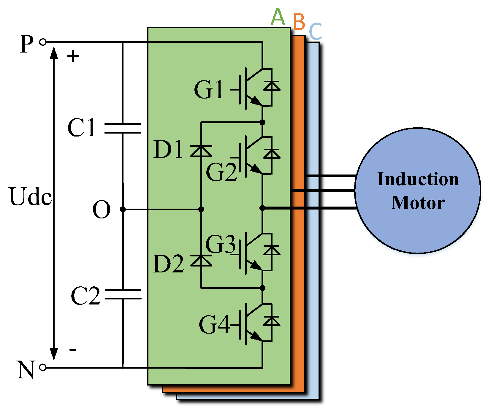
The drive system of induction motor with TL-NPC inverter is shown in
Figure 1. The hardware of the three phases are generally identical in a motor drive system. The output voltage of the inverter is a phase voltage referenced to the neutral point voltage, and the three phases are generally independently controlled. The phase voltage used for the speed observation is the voltage output from the inverter, which is also referenced to the neutral point voltage, so the three phases voltages are independent. This paper only introduces the method of the voltage compensation. This method assumes that the three phases are identical, so only one of the phases is analyzed below, but the specific compensation voltages of the three phases differ according to the voltage and current of each phase.
The switching signal and the ideal supply voltage of the TL-NPC inverter in different switching states are shown in
Figure 2.
Due to it taking a certain amount of time for the IGBT to turn off, in order to prevent a short circuit in the TL-NPC during the switching process, it is necessary to set a dead-time (T
d) delay between G
1/G
3 and G
2/G
4. The gate signal G
1’, G
2’, G
3’, G
4’ with dead-time delay was set as shown in
Figure 3. In addition, after the gate drive signal was applied to the IGBT, it takes a certain amount of time to turn on and off, and the required time is T
on and T
off, respectively. T
on and T
off are not only related to the characteristics of the IGBT, but also the stray parameters of the circuit, and for this reason, the test method is generally used to obtain T
on and T
off. Due to the effects of T
d, T
on, and T
off, the actual supply voltage and the desired voltage will deviate. The T
d, T
on, and T
off are primarily determined by device characteristics and can be obtained from the device datasheet or measured by test methods.
As can be seen from
Figure 3, the voltage deviation due to dead-time delay, turn-on time, and turn-off time during each switching cycle is
where
is the desired voltage and T
s is the switching period.
2.2. Forward Voltage Drops
In a general control system, the influence of forward voltage drop is negligible. However, in order to obtain a precise supply voltage and achieve high-performance rotor speed observation in speed sensorless control systems, it cannot be ignored.
The current path in different switching modes is shown in
Figure 4, where the current flows through two devices in different paths. The IGBTs and the diodes generally have the same voltage- and current-level devices in a TL-NPC inverter, and their difference in forward voltage drop is small. For example, the forward voltage drop of Infineon’s IGBT (Neubiberg, Germany) (FZ3600R17KE3_B2) and diode (DZ3600S17K3_B2) are 2.0 and 1.8 V respectively with the difference being about 10%, and they are often used together in TL-NPC inverters. For the IGBT module (Infineon’s F3L300R12ME4_B23) used in the experimental platform of this paper, which contains the clamped diodes, the forward drop of the IGBT and the diode are 1.75 and 1.65 V respectively, with a difference of about 9%. Hence, if we ignore the difference in voltage drop between the IGBT, antiparallel freewheeling diode, and clamp diode, the total forward voltage drop can be expressed as
where
is the average forward voltage drop of a single device and can be obtained from the datasheet.
The forward voltage drop in different current directions is shown in
Figure 5. Hence, the voltage deviation due to the forward voltage drop can be expressed as
3. Analysis of the Influence of Voltage Error on Rotor Speed Observation
Adaptive control is mainly used for parameter adaptation. The essence of an adaptive control mechanism is to adapt to the controlled system with parameters that need to be estimated. The configuration of model reference adaptive system (MRAS) is illustrated in
Figure 6. There is a reference motor model and the adaptive model as a function of the parameter to be estimated. The adaptive mechanism is used to ensure that the state of the observer converges to the state of the motor.
The equation of state model of a three-phase induction motor in a two-phase synchronous coordinate system can be obtained by the voltage, flux linkage, and inductance equation of the induction motor. If the induction motor stator current and rotor flux are selected as state variables, the induction motor model is as shown in Equation (4)
where
,
,
,
,
,
,
,
,
,
,
,
and
.
,
,
,
, and
are stator resistance, rotor resistance, stator inductance, rotor inductance, and magnetizing inductance, respectively.
From the state Equation (4), we can build an adaptive observer as shown in Equation (5).
where
,
,
,
is the error between the command voltage and the actual voltage. The observed speed can be expressed as
The error equation derived from the induction motor model Equation (4), together with the adaptive full-order observer Equation (5), can be expressed by the following equations:
where
,
,
,
,
.
According to Equation (7), we can get the current error equation as shown in Equations (8)–(10).
The observed rotor speed can be expressed as Equation (11). It can be represented by a block diagram as
Figure 7.
We assume that , , .
According to Equation (8), we can get , , .
Using Mason’s gain formula to process Equation (11), we can get Equation (12). Hence,
Figure 7 can be further represented as
Figure 8.
Figure 9 shows the amplitude of the transfer function under steady state conditions. From the figure, we can see that the lower the rotor speed, the more sensitive the observed speed is to the voltage error. The parameters of the induction motor are shown in
Table 1.
4. Nonlinear Effects Compensation Scheme
In order to improve the performance of the speed observation, it was necessary to make the input voltage of the observer coincide with the supply voltage of the induction motor. In this paper, the output voltage of the inverter was compensated by the principle of volt-second balance. The speed observation uses the voltage command before compensation as the input voltage, thus achieving the goal that the input voltage of the observer is consistent with the supply voltage of the induction motor.
A comprehensive compensation scheme was used to consider multiple factors of dead time and forward voltage drops.
Figure 10 shows the comprehensive voltage compensation block diagram of one phase of a TL-NPC inverter.
Figure 11 shows the control flowchart of the whole procedure of the controller using proposed method.
5. Experimental Results
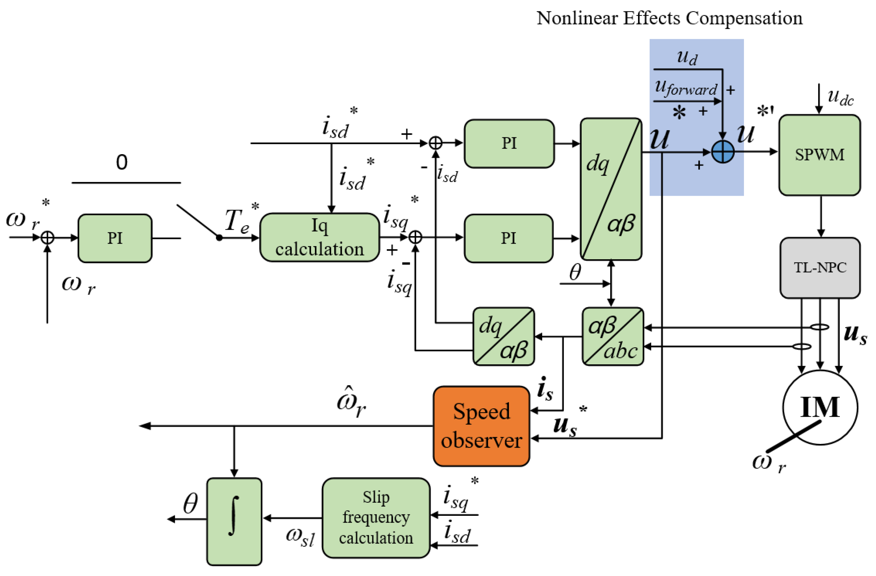
In order to verify the previous analysis, an experimental platform was set up. A TL-NPC inverter fed from a constant DC voltage supply drives an induction motor. The TL-NPC inverter was designed using Infineon FF300R12ME4_B11 IGBT modules. The current controller was implemented on Texas Instruments TMS320F28335 and Altera Cyclone III EP3C25F324 digital signal controllers. The experimental platform control block diagram is shown in
Figure 12. In order to reduce the influence of speed control on the actual speed of the motor, firstly, the speed closed-loop control strategy was used to accelerate the motor to the target speed, and then a constant torque control strategy was adopted, and the constant torque was 0 N∙m by setting the
isq* to 0 A. A high-precision speed encoder was also arranged on the motor to measure the actual speed of the motor. The parameters of nonlinear effects of TL-NPC inverter of the experimental platform are shown in
Table 2.
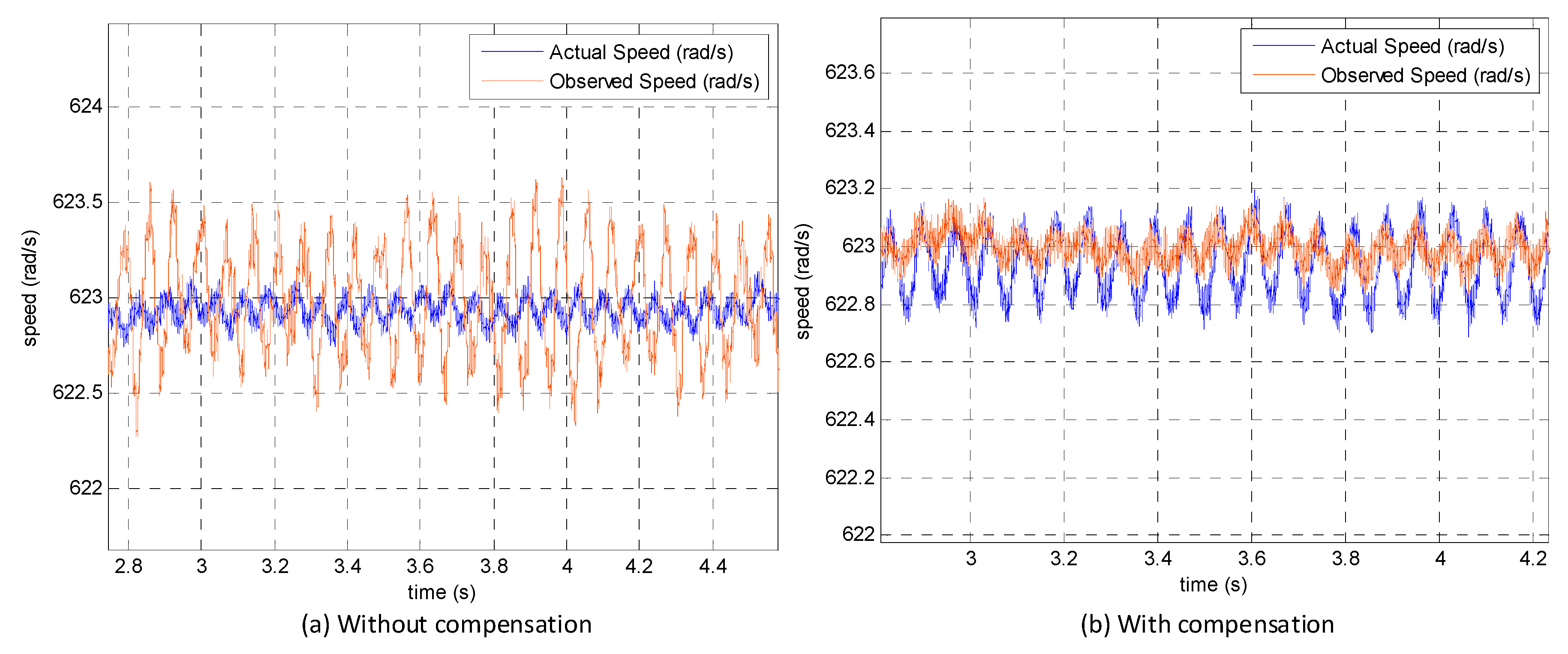
The experimental results of actual speed and observer speed at different speeds are shown in
Figure 13 (7 rad/s),
Figure 14 (70 rad/s),
Figure 15 (140 rad/s),
Figure 16 (280 rad/s),
Figure 17 (420 rad/s), and
Figure 18 (623 rad/s). From these figures, we can see that the lower the speed, the greater the fluctuation in the observed speed when no voltage error compensation is performed. The lower the speed, the more obvious the voltage error compensation is when compared to the accurate speed observation. The speed errors of the observer speed without and with the proposed compensation are shown in
Figure 19. The experimental results were consistent with the previous analysis.
6. Conclusions
In the model reference adaptive speed observer, the induction motor supply voltage is used as the input of the reference model. The command voltage calculated by the controller is generally used instead of the actual supply voltage in the drive system. However, due to nonlinear effects of the inverter, the voltage calculated by the controller is different from the actual supply voltage, resulting in a speed observation deviation. A comprehensive compensation scheme considering the dead-time delay and device forward voltage drop was proposed to improve the accuracy of speed observation, which was verified in an experimental platform. The main conclusions of this paper are summarized as follows:
The transfer function expression of the inverter output voltage error and the observed rotational speed error was derived. The transfer function indicated that the inverter output voltage error will result in inaccurate observation speed.
The transfer function indicated that the lower the speed, the more obvious the influence of nonlinear effects of the TL-NPC inverter on the speed observation.
The proposed nonlinear effects of the TL-NPC inverter compensation method were effective for speed observation. The compensation method was verified by the experiment.
In conclusion, the nonlinear effects compensation method is also suitable for five-level and other multilevel inverters for induction motor sensorless drive systems.
Author Contributions
Conceptualization, P.L. and L.Z.; Methodology, B.O.; Software, Y.L.; Validation, P.L., L.Z. and B.OZ.; Formal Analysis, Y.L.; Writing—Original Draft Preparation, P.L.; Writing—Review & Editing, Y.L.; Visualization, L.Z.; Supervision, B.O.
Funding
This research received no external funding.
Conflicts of Interest
The authors declare no conflict of interest.
References
- Zhang, Y.; Zhu, J. An Improved Direct Torque Control for Three-Level Inverter-Fed Induction Motor Sensorless Drive. IEEE Trans. Power Electron. 2012, 27, 1502–1513. [Google Scholar] [CrossRef]
- Habibullah, M.; Lu, D.; Xiao, D.; Fletcher, J.E. Muhammed Fazlur Rahman. Predictive Torque Control of Induction Motor Sensorless Drive Fed by a 3L-NPC Inverter. IEEE Trans. Ind. Inform. 2017, 13, 60–70. [Google Scholar] [CrossRef]
- Zhang, Y.; Bai, Y.; Yang, H.; Zhang, B. Low Switching Frequency Model Predictive Control of Three-Level Inverter-Fed IM Drives with Speed-Sensorless and Field-Weakening Operations. IEEE Trans. Ind. Electron. 2019, 66, 4262–4272. [Google Scholar] [CrossRef]
- Liu, P.; Duan, S.; Yao, C.; Chen, C. A Double Modulation Wave CBPWM Strategy Providing Neutral-Point Voltage Oscillation Elimination and CMV Reduction for Three-Level NPC Inverters. IEEE Trans. Ind. Electron. 2018, 65, 16–26. [Google Scholar] [CrossRef]
- López, I.; Ceballos, S.; Pou, J.; Zaragoza, J.; Andreu, J.; Ibarra, E.; Konstantinou, G. Generalized PWM-Based Method for Multiphase Neutral-Point-Clamped Converters with Capacitor Voltage Balance Capability. IEEE Trans. Power Electron. 2017, 32, 4878–4890. [Google Scholar] [CrossRef]
- Orfanoudakis, G.I.; Sharkh, S.M.; Yuratich, M.A. Analysis of Dc-Link Capacitor Current in Three-Level Neutral Point Clamped and Cascaded H-Bridge Inverters. IET Power Electron. 2013, 6, 1376–1389. [Google Scholar] [CrossRef]
- Yang, G.; Chin, T.-H. Adaptive-speed identification scheme for a vector-controlled speed sensorless inverter-induction motor drive. IEEE Trans. Ind. Appl. 1993, 29, 820–825. [Google Scholar] [CrossRef]
- Lee, C.-M.; Chen, C.-L. Observer-based speed estimation method for sensorless vector control of induction motors. Proc. IEE Control Theory Appl. 1998, 145, 359–363. [Google Scholar] [CrossRef]
- Yan, Z.; Jin, C.; Utkin, V.I. Sensorless sliding-mode control of induction motors. IEEE Trans. Ind. Electron. 2000, 47, 1286–1297. [Google Scholar]
- Rehman, H.; Derdiyok, A.; Gûven, M.K.; Xu, L. A new current model flux observer for wide speed range sensorless control of an induction machine. IEEE Trans. Power Electron. 2002, 17, 1041–1048. [Google Scholar] [CrossRef]
- Patel, P.J.; Patel, V.P.; Tekwani, P.P.N. Pulse-based dead-time compensation method for self-balancing space vector pulse width-modulated scheme used in a three-level inverter-fed induction motor drive. IET Power Electron. 2011, 4, 624–631. [Google Scholar] [CrossRef]
- Zhou, D.; Rouaud, D.G. Dead-time effect and compensations of three level neutral point clamp inverters for high performance drive applications. IEEE Trans. Power Electron. 1997, 14, 397–402. [Google Scholar]
- Minshull, S.R.; Bingham, C.M.; Stone, D.A.; Foster, M.P. Compensation of Nonlinearities in Diode-Clamped Multilevel Converters. IEEE Trans. Ind. Electron. 2010, 57, 2651–2658. [Google Scholar] [CrossRef] [Green Version]
- Wang, S.; Song, W.; Ma, J.; Zhao, J.; Feng, X. Study on Comprehensive Analysis and Compensation for the Line Current Distortion in Single-Phase Three-Level NPC Converters. IEEE Trans. Ind. Electron. 2018, 65, 2199–2211. [Google Scholar] [CrossRef]
Figure 1.
The drive system of induction motor with the three-level neutral-point clamped (TL-NPC) inverter.
Figure 1.
The drive system of induction motor with the three-level neutral-point clamped (TL-NPC) inverter.
Figure 2.
The switching signal and ideal supply voltage of the TL-NPC inverter.
Figure 2.
The switching signal and ideal supply voltage of the TL-NPC inverter.
Figure 3.
The gate signal with the dead-time delay and actual voltage of the TL-NPC.
Figure 3.
The gate signal with the dead-time delay and actual voltage of the TL-NPC.
Figure 4.
The current path in the different switching modes of the TL-NPC.
Figure 4.
The current path in the different switching modes of the TL-NPC.
Figure 5.
The forward voltage drops in different current directions.
Figure 5.
The forward voltage drops in different current directions.
Figure 6.
The general configuration of the model reference adaptive systems.
Figure 6.
The general configuration of the model reference adaptive systems.
Figure 7.
The block diagram of rotor speed observation with input voltage error.
Figure 7.
The block diagram of rotor speed observation with input voltage error.
Figure 8.
The general configuration of the model reference adaptive systems.
Figure 8.
The general configuration of the model reference adaptive systems.
Figure 9.
The amplitude of the transfer function of voltage error and observed speed.
Figure 9.
The amplitude of the transfer function of voltage error and observed speed.
Figure 10.
The comprehensive voltage compensation block diagram of one phase of a TL-NPC inverter.
Figure 10.
The comprehensive voltage compensation block diagram of one phase of a TL-NPC inverter.
Figure 11.
The control flowchart showing the whole procedure of the controller with the proposed method.
Figure 11.
The control flowchart showing the whole procedure of the controller with the proposed method.
Figure 12.
The amplitude of the transfer function of voltage error and observed speed.
Figure 12.
The amplitude of the transfer function of voltage error and observed speed.
Figure 13.
The experimental results of actual speed and observer speed at 7 rad/s.
Figure 13.
The experimental results of actual speed and observer speed at 7 rad/s.
Figure 14.
The experimental results of actual speed and observer speed at 70 rad/s.
Figure 14.
The experimental results of actual speed and observer speed at 70 rad/s.
Figure 15.
The experimental results of actual speed and observer speed at 140 rad/s.
Figure 15.
The experimental results of actual speed and observer speed at 140 rad/s.
Figure 16.
The experimental results of actual speed and observer speed at 280 rad/s.
Figure 16.
The experimental results of actual speed and observer speed at 280 rad/s.
Figure 17.
The experimental results of actual speed and observer speed at 420 rad/s.
Figure 17.
The experimental results of actual speed and observer speed at 420 rad/s.
Figure 18.
The experimental results of actual speed and observer speed at 623 rad/s.
Figure 18.
The experimental results of actual speed and observer speed at 623 rad/s.
Figure 19.
The speed errors of observer speed without and with the proposed compensation.
Figure 19.
The speed errors of observer speed without and with the proposed compensation.
Table 1.
Parameters of the induction motor.
Table 1.
Parameters of the induction motor.
| Rs | Stator resistance | 2.33 Ω |
| Rr | Rotor resistance | 2.12 Ω |
| Ls | Stator inductance | 0.2994 H |
| Lr | Rotor inductance | 0.3007 H |
| Lm | Magnetizing inductance | 0.2866 H |
| P | Pole pairs | 2 |
Table 2.
The parameters of the nonlinear effects of the experimental platform.
Table 2.
The parameters of the nonlinear effects of the experimental platform.
| Ts | Switching cycle | 250 μs |
| Td | Dead time | 5 μs |
| Ton | Turn on delay time | 2 μs |
| Toff | Turn off delay time | 2.5 μs |
| uce | IGBT and diode forward voltage | 1.75 V |
© 2019 by the authors. Licensee MDPI, Basel, Switzerland. This article is an open access article distributed under the terms and conditions of the Creative Commons Attribution (CC BY) license (http://creativecommons.org/licenses/by/4.0/).


