Mobile-Oriented Future Internet: Implementation and Experimentations over EU–Korea Testbed
by
 ,
,
Ji-In Kim
1 ,
,
Nak-Jung Choi
2,
Tae-Wan You
3,
Heeyoung Jung
3,
Young-Woo Kwon
2,* and
Seok-Joo Koh
3
1
Research Institute, Sillasystem Co. Ltd., Daegu 41566, Korea
2
School of Computer Science and Engineering, Kyungpook National University, Daegu 34129, Korea
3
Electronics and Telecommunication Research Institute, Daejeon 41566, Korea
*
Author to whom correspondence should be addressed.
Electronics 2019, 8(3), 338; https://doi.org/10.3390/electronics8030338
Submission received: 12 November 2018
/
Revised: 4 March 2019
/
Accepted: 12 March 2019
/
Published: 20 March 2019
(This article belongs to the Special Issue Mobile Oriented Future Internet (MOFI): Architectural Designs and Experimentations)
Abstract
:Today’s mobility management (MM) architectures, such as Mobile Internet Protocol (IP) and Proxy Mobile IP, feature integration of data and control planes, as well as centralized mobility control. In the existing architecture, however, the tight integration of the data and control planes can induce a non-optimal routing path, because data packets are delivered via a central mobility agent, such as Home Agent and Local Mobility Anchor. Furthermore, the centralized mobility control mechanism tends to increase traffic overhead due to the processing of both data and control packets at a central agent. To address these problems, a new Internet architecture for the future mobile network was proposed, named Mobile-Oriented Future Internet (MOFI). The MOFI architecture was mainly designed as follows: (1) separation of data and control planes for getting an optimal data path; (2) distributed identifier–locator mapping control for alleviating traffic overhead at a central agent. In this article, we investigate the validity of the MOFI architecture through implementation and experimentations over the European Union (EU)–Korea testbed network. For this purpose, the MOFI architecture is implemented using OpenFlow and Click Modular Router over a Linux platform, and then it is evaluated over the locally and internationally configured EU–Korea testbed network. In particular, we operate two realistic communication scenarios over the EU–Korea testbed network. From the experimentation results, we can see that the proposed MOFI architecture can not only provide the mobility management efficiently, but also support the backward compatibility for the current IP version 6 (IPv6) applications and an Internet Protocol network.
1. Introduction
As the current Internet architecture was designed for fixed network environments regardless of mobile network environments, future Internet architectures for the emerging network environments are widely discussed in recent research. Of those discussed, the incremental and clean-state approaches mainly dominate the future Internet research. In the incremental approach, one state is moved to another state with incremental patches, while, in the clean-slate approach, all the network stacks are redesigned from scratch to offer better abstractions and improved performance, as well as providing similar functionality based on new core principles [1]. In the past, Internet was wildly successful using the incremental approach. However, due to the rapidly emerging mobility technologies, today’s Internet architecture faces many challenges. As a result, the clean-slate approach began receiving much attention to design the future Internet for mobile environments. However, applying the clean-slate approach to the current Internet infrastructure still incurs a deployment burden that requires the replacement or update of all network devices including routers, switches, and even hosts. As a result, in South Korea, research activities on future Internet architectures focus on Mobile-Oriented Future Internet (MOFI) [2], which is a new mobility management architecture based on the incremental approach. The great advantage of employing the incremental approach is that the new architecture and Internet services developed on the new architecture can be easily deployed over the current Internet infrastructure.
The MOFI architecture has three architectural components as follows: (1) host identifier and local locator (HILL), (2) query-first data delivery (QFDD), and (3) dynamic and distributed mapping system (DMS). Specifically, in HILL, each host has a globally unique host identifier (HID) for end-to-end communications, whereas the locator (LOC) of a network router is locally used for packet delivery. In QFDD, a location query is first executed before data delivery to obtain an optimal path between two connected hosts. In DMS, the mapping information between hosts is managed in a dynamic, distributed way. In order to provide compatibility with the existing Internet infrastructure, a host’s IP address becomes a host identifier, and an access router’s IP address is used as a locator.
Because the MOFI architecture only modifies the network devices used as a switch and a regional gateway for the data plane and a controller for the control plane, this design choice has a great advantage for deployment. Specifically, the proposed MOFI architecture can operate in the existing Internet Protocol version 6 (IPv6) Internet environment without any modification of the existing network infrastructure through LOC-based communications. Moreover, HID-based application services also can be used as is by utilizing the existing network infrastructure. As a result, while other architectures based on the clean-slate approach require the development and deployment burden of necessary devices and application services, the newly proposed MOFI architecture based on the incremental approach does not require any development of necessary application services and devices, thereby enabling fast deployment of Internet services in the new Internet infrastructure.
To evaluate the superiority of the newly proposed architecture, the architecture needs to be assessed through a set of simulations using NS3 [3] or OPNET [4] or real experiments on testbeds. Considering the scale of the Internet, the architecture needs to be evaluated on large-scale testbeds rather than simulations. Furthermore, because the MOFI architecture was developed in an incremental way, it must ensure that the new architecture can provide compatibility between existing Internet protocol stacks. To that end, we implemented the MOFI architecture on top of a Linux platform and then constructed a testbed across Korea and the European Union (EU) for the evaluation. More specifically, the data plane of the MOFI architecture was implemented using OpenFlow [5] and the Click Modular Router [6]. The control plane of the MOFI architecture was implemented using the OpenFlow, Click Modular Router, and UDP (User Datagram Protocol). This global testbed was established for the verification of the MOFI architecture.
The rest of this article is organized as follows: Section 2 presents the technical background that motivates our research. Section 3 summarizes an overview of the MOFI architecture. Section 4 presents the implementation details of the MOFI architecture and the globally constructed testbed between EU and Korea. Section 5 describes service scenarios and discusses the result demonstrated on the testbed. Section 6 concludes this article.
2. Background
In the last decade, both incremental and clean-state approaches dominated the future Internet research. In the incremental approach, a future Internet architecture is developed step by step based on the prior Internet architecture and infrastructure and, thus, existing Internet infrastructures and services can be used without any modification. The Internet was wildly successful using the incremental approach, as shown in the example of Mobile IP [7,8].
On the other hand, in the clean-state approach, an Internet architecture is newly designed and developed so as to maximize performance benefits. For example, the following research activities, including 4WARD [9,10,11], FIND (Future Internet Design) [12], MobilityFirst [13,14,15], GENI 9 (Global Environment for Network Innovations) [16], NDN (Named Data Networking) [17] were conducted based-on the clean-slate approach. 4WARD is an EU-initiated project that employed the concept of network virtualization, and a total of 37 partners were involved. FIND and GENI are NSF (National Science Foundation)-initiated projects to develop a new future Internet architecture. Through the GENI project, a new infrastructure was provided, and, through the FIND project, the proposed architectures were implemented and tested. To support new Internet features such as multicast, anycast, multi-path, and context-aware services, the MobilityFirst architecture employed a clean-slate approach. More recently, the NDN project was proposed to overcome the weakness of the current Internet architecture and to provide emerging communication patterns.
However, applying the clean-slate approach to the current Internet infrastructure requires additional development and deployment efforts. Thus, when moving toward future Internet, it is challenging to determine the transitioning time that meets all the requirements of a newly designed Internet architecture. In this article, we report our effort to construct a realistic testbed across the EU and South Korea. In addition, we tested the MOFI architecture implemented in an incremental way. In the discussion below, we describe our MOFI implementation and testbed construction in detail.
3. MOFI Architecture: Overview
3.1. Architectural Features
The Mobile-Oriented Future Internet (MOFI) architecture is an enhanced mobility management architecture that solves the problems that the current Internet faces. Table 1 shows the comparison of the current Internet’s problems and MOFI design principles.
In the identifier–locator structure, the MOFI architecture uses the IP address of a host as host ID (HID), the media access control (MAC) address of the switch (SW), and the IP address of the regional gateway (R-GW), in which the host is attached as a locator (LOC).
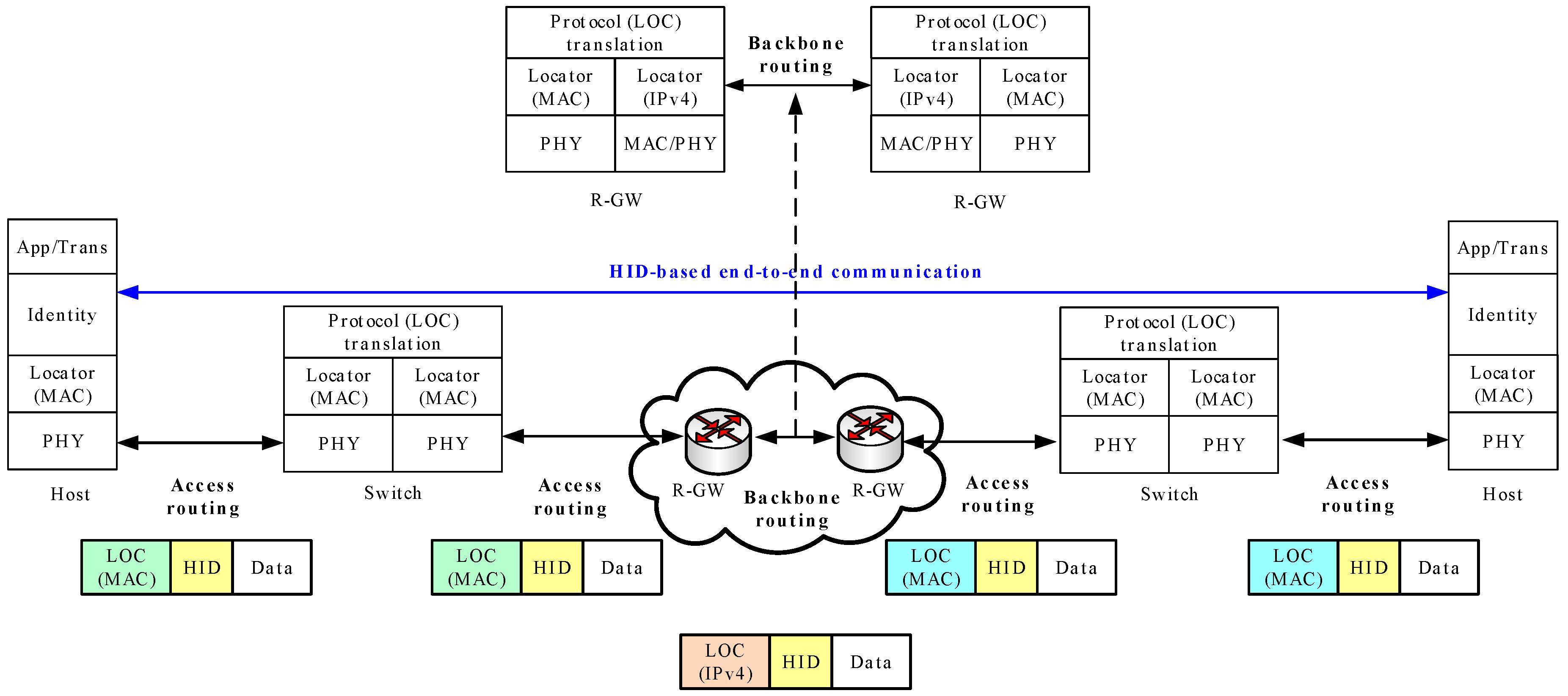
Figure 1 shows a protocol model for the data delivery in MOFI. In this figure, the network layer of MOFI is divided into the communication and delivery layer. The communication layer can be implemented as a shim layer protocol between the transport and network layer. The HID field used for end-to-end communication between two end hosts is contained in the identity header. The delivery layer is divided into access delivery protocol (ADP) and backbone delivery protocol (BDP), which are used to deliver data packets between end hosts. For intra-domain data delivery, each SW translates ADPs. During this process, the identity header containing source and destination HIDs can be referred to by the SW, in which the LOC query operation of DMS is executed. For the inter-domain data delivery across different domains, each R-GW translates ADP to BDP. During this process, the identity header is referred to by R-GW, in which the LOC query operation of DMS is performed.
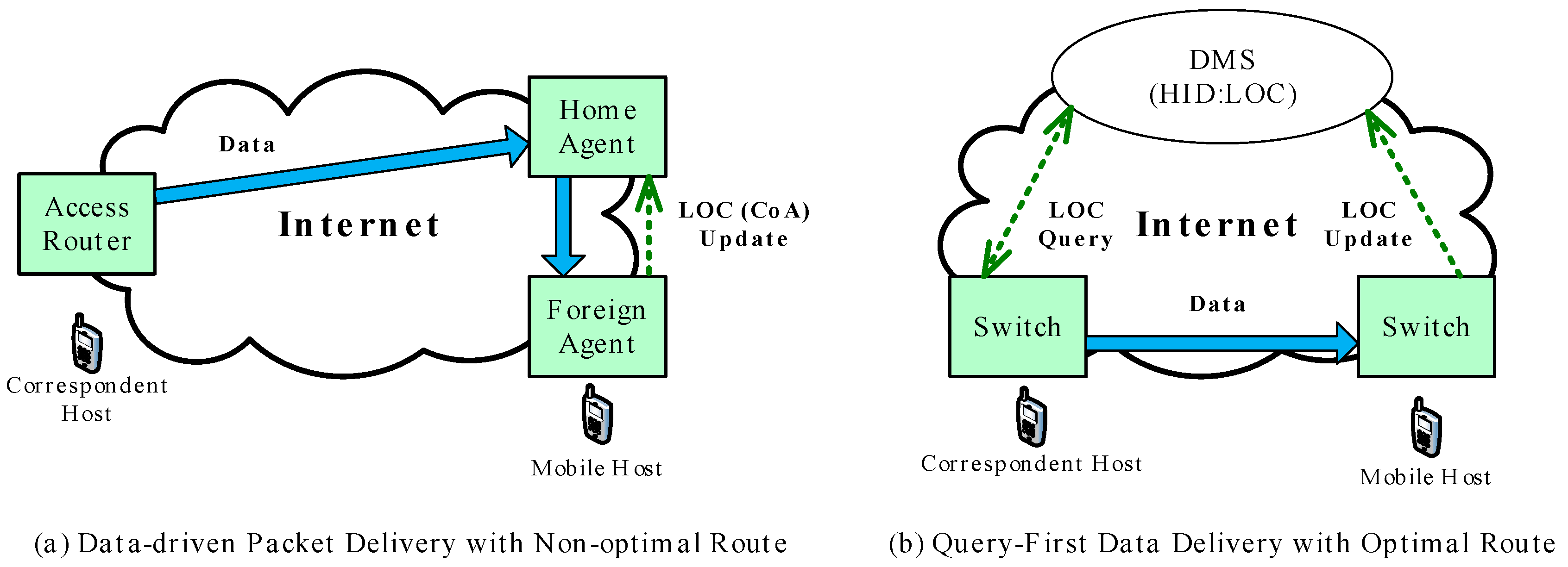
The data-driven packet delivery model used by current mobility protocols can induce non-optimal routes. In MOFI, therefore, we adopted the query-first data delivery approach, in which the LOC query operation is performed before transmitting data to find an optimal route between the two communicating hosts. Figure 2 compares the data-driven packet delivery and the query-first data delivery used in our approach.
In the data-driven packet delivery depicted in Figure 2a a mobile host (MH) updates its care of address (CoA) with LOC at the home agent (HA), when attached to a foreign agent (FA). The correspondent host (CH) sends data packets to the HA, which forwards these packets to the MH via the FA. However, this delivery mechanism can induce a non-optimal route. In Figure 2b, the HID and LOC of the MH are registered with DMS in the mobile environment. When the CH sends a data packet to the MH, a switch on the CH’s side finds the LOC of the MH using the LOC query operation with DMS. Then, finally, the data packet is directly delivered to the MH. This data delivery mechanism provides better routing paths.
Figure 3 shows a hash-based distributed HID–LOC mapping management model used in the MOFI architecture. In the figure, each domain has its distributed mobility controller (DMC) for the mapping management information of mobile hosts. A selected DMC (S-DMC) is determined for each host using a hash function; for example, a simple modulo operation (%) can be used to determine the S-DMC for a host, such as “(HID of the host) % (the number of DMCs in the Internet)”. Once S-DMC is determined for a specific host, the associated HID–LOC mapping information for the host will be maintained by the S-DMC.
Table 2 gives an overview of caches and registers used in MOFI. For each data and control plane, MOFI uses the following caches and registers: local binding cache (LBC), data forwarding cache (DFC), local mapping register (LMR), and serving mapping register (SMR). In the control plane, DMC maintains an HID–LOC mapping table (i.e., LMR) for its local host and SMR containing the domain information associated with each HID. In the data plane, SW and R-GW maintain the DFC that is updated by an LOC query operation for data forwarding. To operate HID–LOC mapping control, the operation is classified into the two operations: HID–LOC binding operations and LOC query operation for data delivery. These operations are described in the upcoming sections.
3.2. HID–LOC Mapping Control Operations
In MOFI, the HID–LOC mapping control is divided into two operations including HID–LOC binding and LOC query. Furthermore, the LOC query operates in two modes—intra- and inter-domain. Thus, in this article, we discuss the three following cases: an HID–LOC binding operation, an LOC query operation in intra-domain, and an LOC query operation in inter-domain.
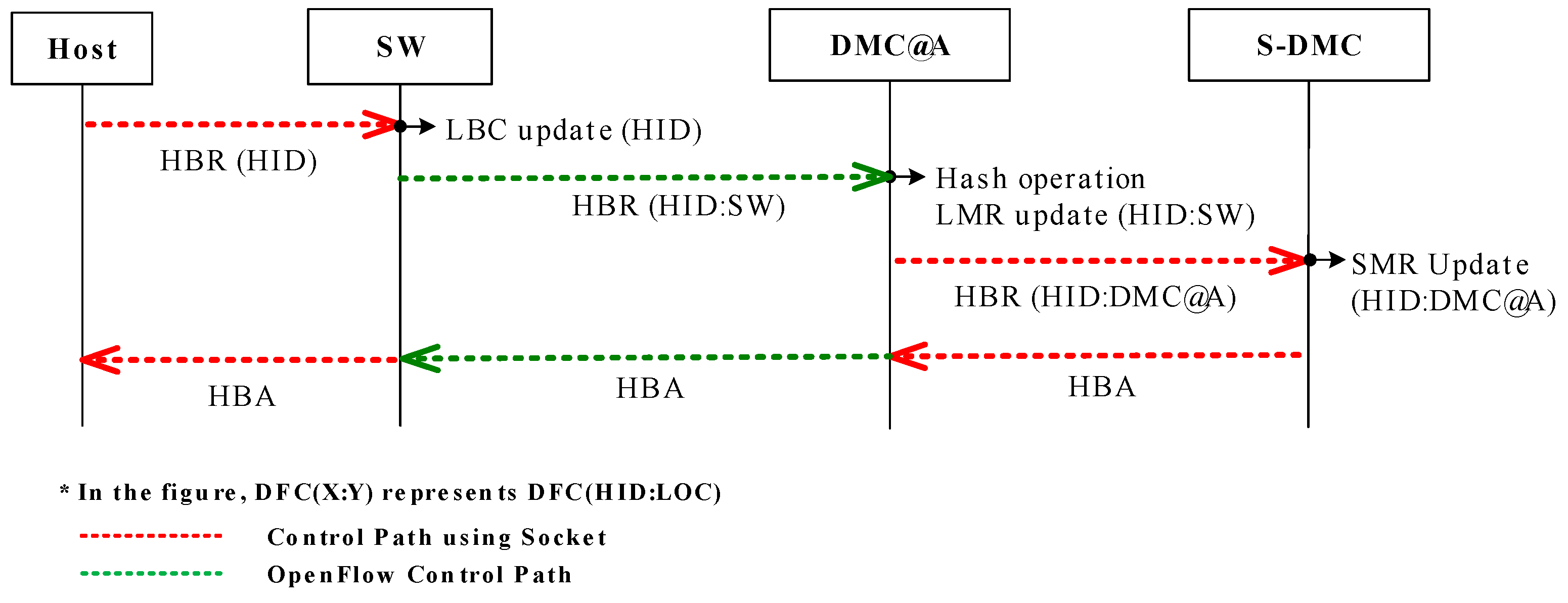
With the network attachment of a host, the HID–LOC binding operation is initiated. As described in Figure 4, during the binding operation, the HID of the host is registered with the SW attached to the host. Then, the SW updates the LBC with a message received from the host to record the HID of the host. Then, the SW sends an HID binding request (HBR) message to the DMC that the host belongs to. At the same time, the DMC receives the HBR message from the SW. The DMC updates its LMR and finds the selected DMC (S-DMC) that is selected for the host. In the case that the DMC becomes the S-DMC, the DMC sends an HBR message to the S-DMC. This HBR message contains the HID of the host and the LOC of SW. After successful HID–LOC binding, the S-DMC updates its SMR and responds to the DMC with an HID binding acknowledgement (ACK) (HBA) message, which is also forwarded to the host through the SW.
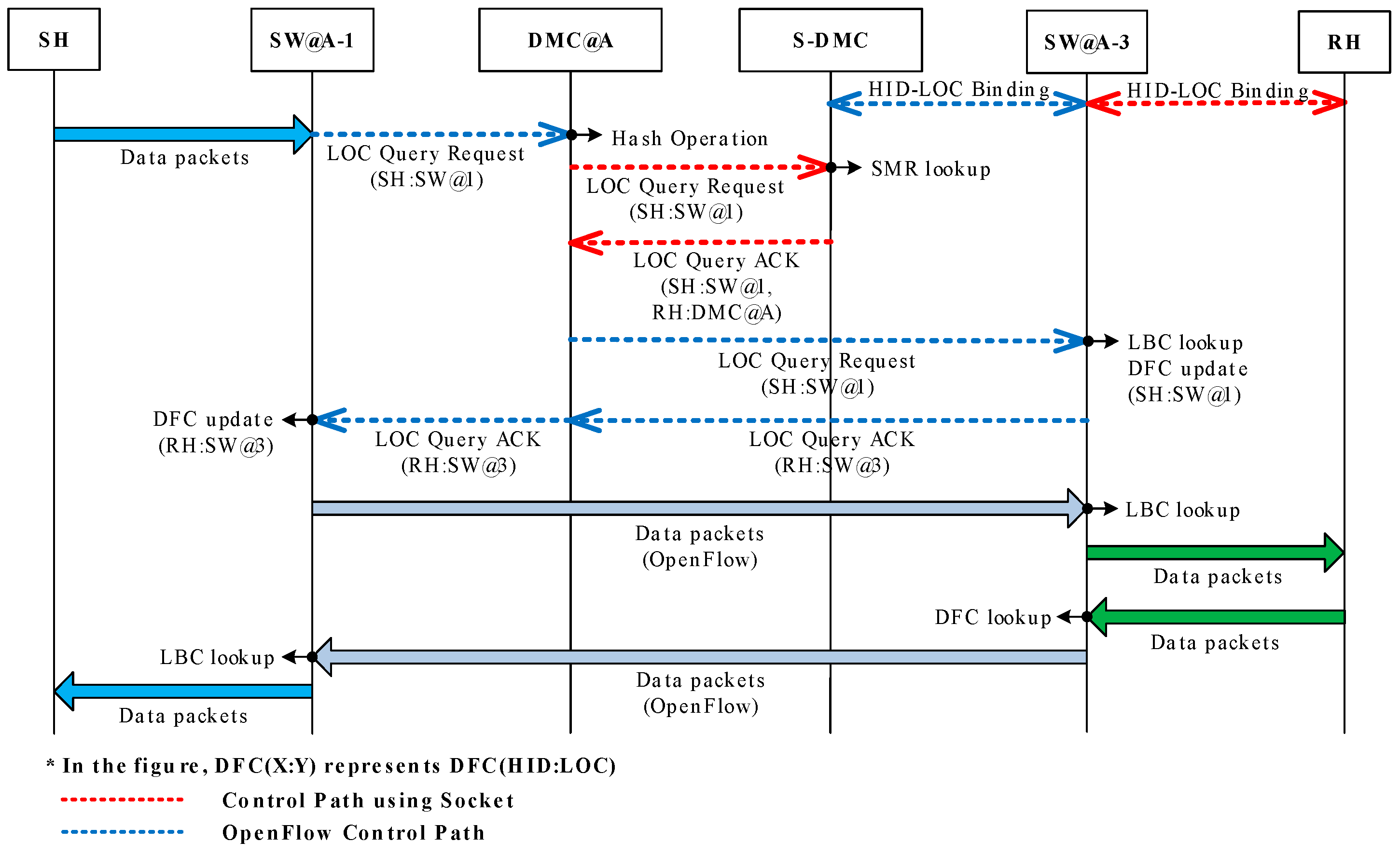
Figure 5 shows the intra-domain LOC query operations for data delivery. Once a data packet arrives from send host (SH), the SW (SW@A-1) sends an LOC query request (LQR) message to the DMC. Then, the DMC finds the receive host (RH)’s S-DMC using a hash function, and forwards the LQR message to the S-DMC. Upon receiving the LQR message from the DMC, the S-DMC looks up the SMR and responds to the DMC using the LOC query ACK (LQA) message. When the DMC receives the LQA message from the S-DMC, the DMC forwards it to the SW (SW@A-3) which belongs to the RH. When the SW of the RH receives the LQR message from the SW of the SH, the SW of the RH updates its DFC and looks up the LBC. After the LBC look-up, the SW of the RH responds to the SW of the SH through the DMC. When receiving the LQA message, the SW of the SH updates its DFC. Finally, the SW of the SH can exchange data packets with the SW of the RH through an optimal path.
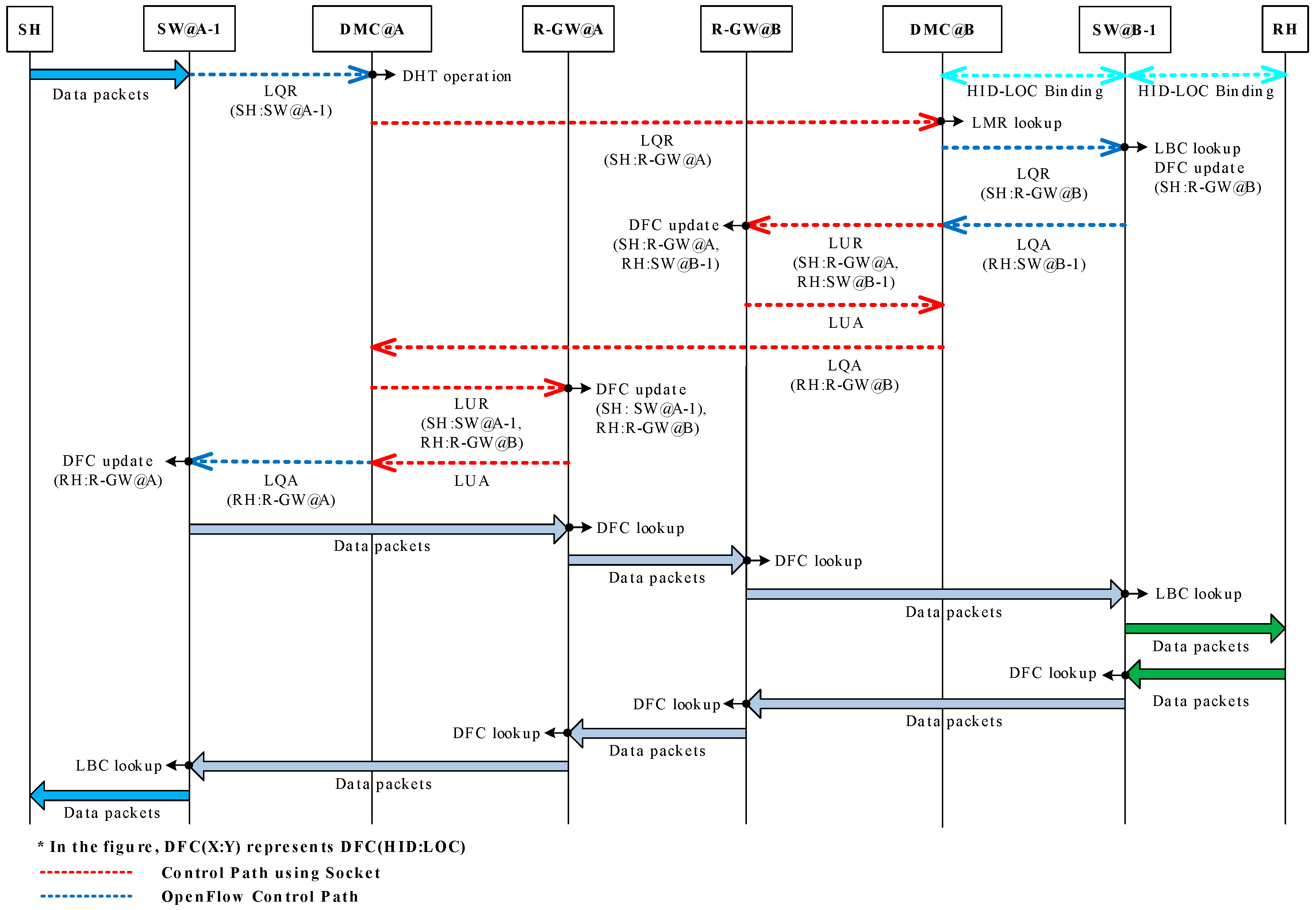
Figure 6 shows inter-domain LOC query operations for data delivery, in which the RH exists in its own network domain with the S-DMC. The inter-domain LOC query operation is the same as the intra-domain LOC query operation until the SH’s DMC sends an LQR message to the S-DMC. On receiving the LQR message, the S-DMC looks up the LMR and recognizes the existence of the RH in the same network. In this case, the S-DMC is the same as the DMC of the RH and sends an LQR message to the RH’s SW. Receiving the LQR message from the RH’s DMC, RH’s SW looks up the LBC and updates the DFC with the received LQR message. The RH’s SW responds to the LQA message to the RH’s DMC. When the RH’s DMC receives the LQA message, the RH’s DMC sends an LOC update request (LUR) message to its R-GW to update the R-GW’s DFC. Then, the R-GW updates its DFC and responds to its DMC by sending an LOC update ACK (LUA) message. As a result, both data and control planes can be completely separated. Then, the RH’s DMC sends an LQA message to the SH’s DMC. Once the SH’s DMC receives the LQA message, the SH’s DMC can exchange the LUR and LQA messages with its GW to update the DFC. After that, the SH’s DMC sends the LQA message to the SH’s SW. Upon receiving the LQA message, the SH’s SW updates its DFC. Finally, the SH’s SW can exchange data packets being sent to the RH’s SW through the optimal path that includes the R-GWs.
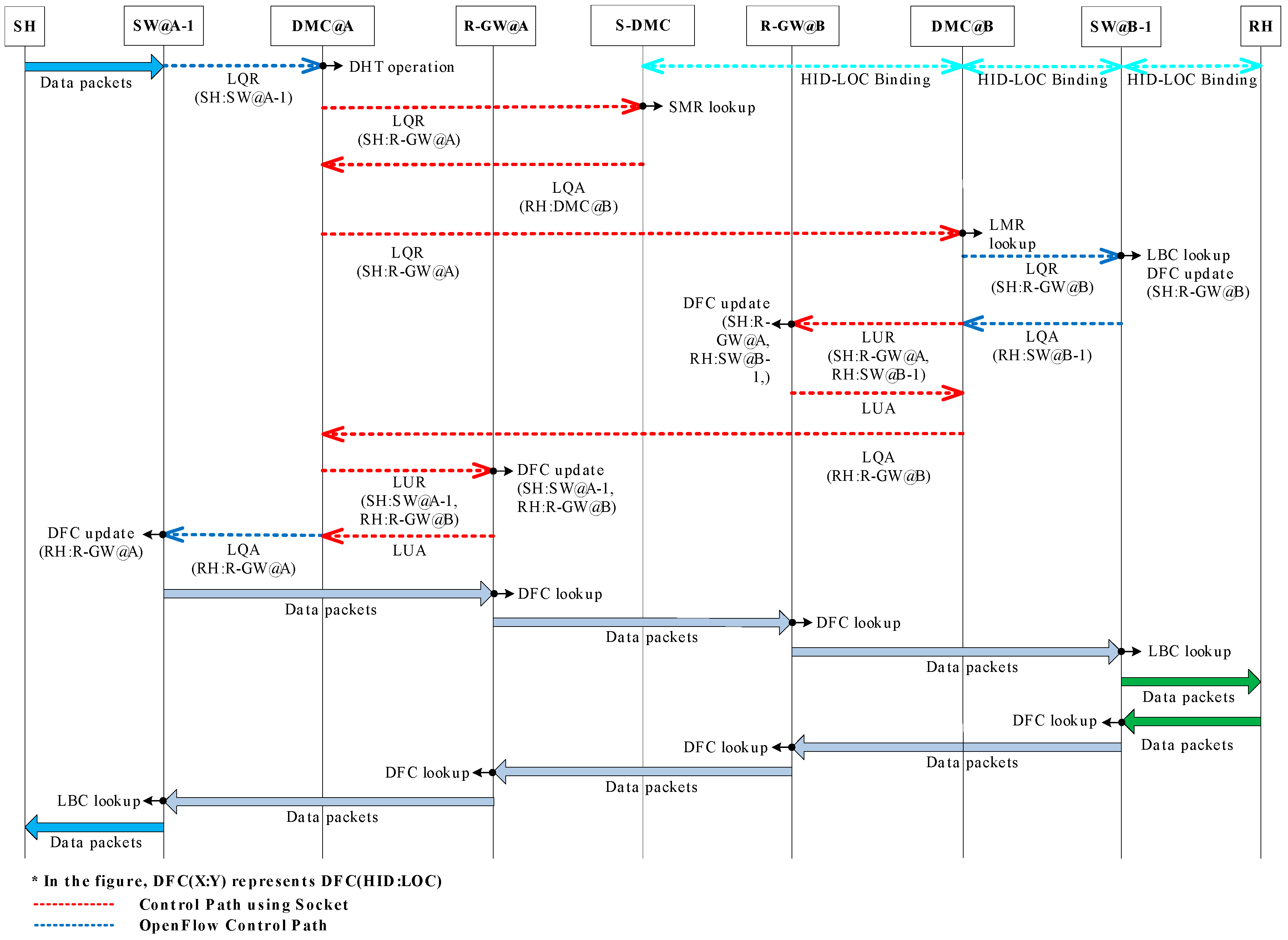
Figure 7 shows inter-domain LOC query operations for data delivery. In this case, the RH and S-DMC exist in different network domains. The inter-domain LOC query operation is the same as the intra-domain LOC query operation until the SH’s DMC receives an LQA message from the S-DMC. Upon receiving the LQA message, the SH’s DMC sends an LQR message to the RH’s DMC. When the RH’s DMC receives the LQR message from the SH’s DMC, it is the same as the inter-domain LOC query operations, in which the RH exists in its own network with the S-DMC.
3.3. Data and Control Packets
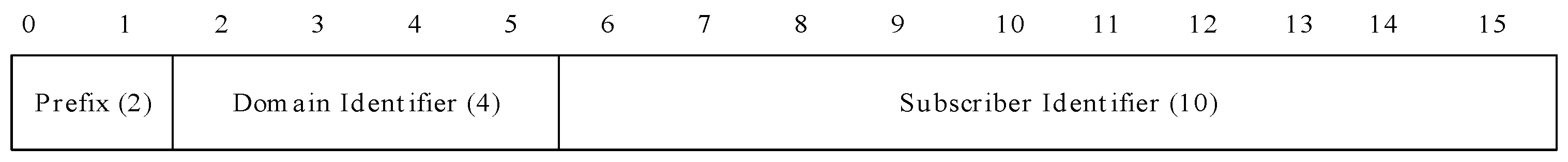
In MOFI, the HID is constructed with 2 bytes of a prefix, 4 bytes of a domain identifier, and 10 bytes of a subscriber identifier, as shown in Figure 8. The prefix field is not used in the current implementation. The domain identifier field is used for identifying a domain associated with the HID or a host. MOFI uses an autonomous system number (ASN) as a domain ID. For a 4-byte representation of a legacy 2-byte ASN, the first 2 bytes are set to “0” [18]. A subscriber identifier is allocated to each host by a domain administrator. Each domain can use this field as a “sub-domain ID” depending on its policy for HID management.
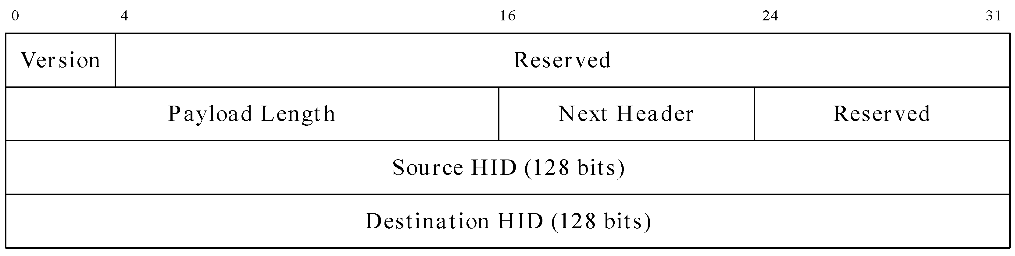
The identity header is newly defined for the end-to-end data communication between two hosts. It is not responsible for data delivery or routing. That is, the HID contained in the identity header is not used for routing data packets in the network. Instead, it is used for the end-to-end communication using an upper layer transport layer protocol and a socket interface with an application program. In MOFI, the identity header format was designed to provide backward compatibility with the current IPv6 header, as shown in Figure 9.
The identity header is similar to the current IPv6 header. The only difference is the absence of a traffic class, flow label, and hop limit. Instead, those fields are reserved. The version field is compatible with the current IP version. Next, the reserved field is set to 0. The payload length field is the length of the payload (in bytes) following this identity header. The next header field is the same with the next header of thIPv6 header. Furthermore, the second reserved field is reserved for the future use. The source HID and destination HID fields are used for HIDs of the source and destination.
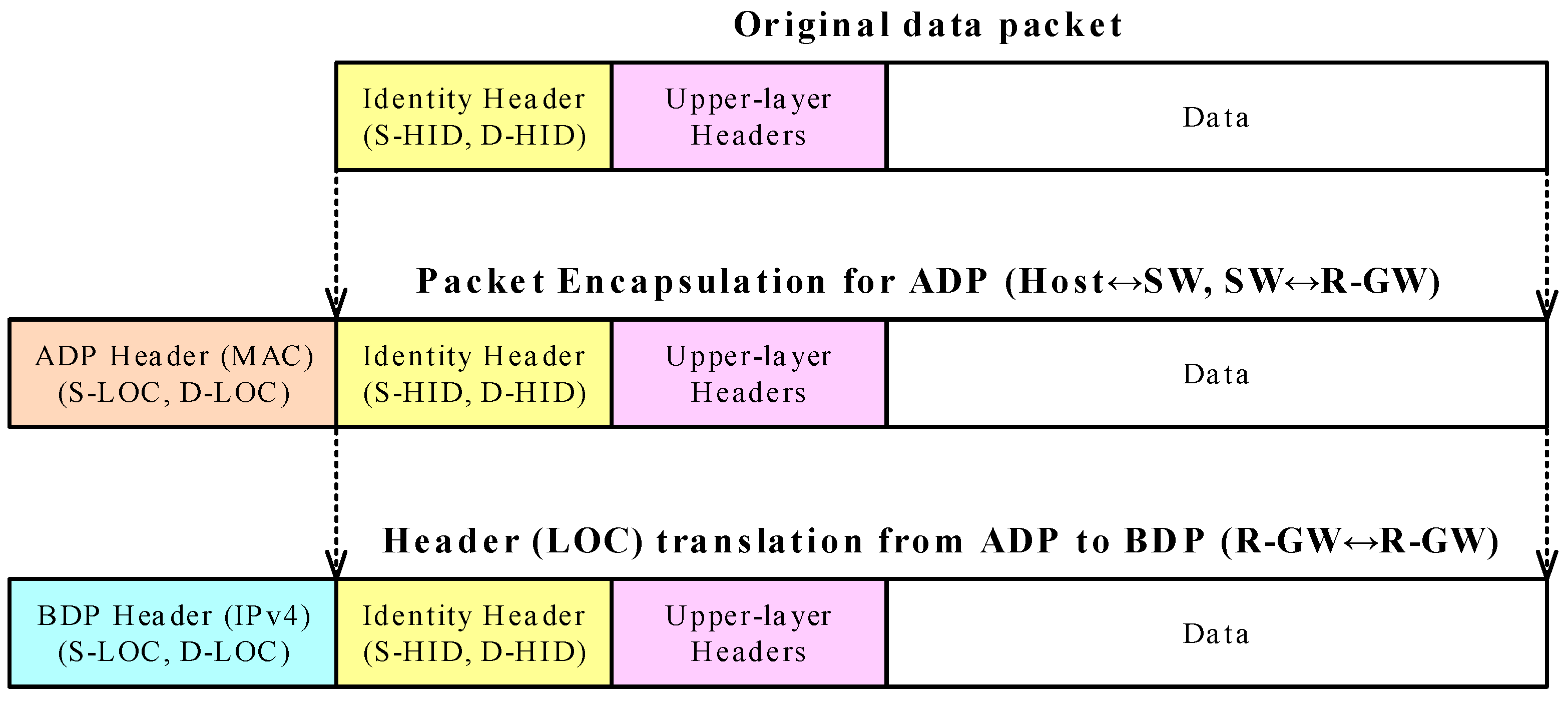
Figure 10 shows the structure of data packets. For data delivery, each host constructs a data packet with the identity. For intra-domain access network delivery, an original packet is encapsulated by adding the ADP header. For inter-domain backbone network delivery, each R-GW translates an ADP header into a BDP header. In this article, the format of the ADP header is a MAC header, while the format of the BDP header is an IPv4 header.
In the control plane, there are six packets for HID–LOC mapping control. Table 3 shows the list of the control messages used in MOFI.
In MOFI, HBR and HBA messages are used for updating HID binding information between a host and R-GW. The LQR and LQA messages are used for LOC query operations for finding an optimal route. The LUR and LUA messages are used for updating the DFC for data delivery.
Each control message is encapsulated into a transport layer protocol that has a 20-byte common header and variable length parameters, as illustrated in Figure 11.
Figure 12 shows the common header format. The message type is an encoding value of the message shown in Table 3. The flag is used for various flags, which are described for each message. The total length field is the length of the message in bytes, including a common header and parameters. The HID field is the HID of the host associated with the corresponding message.
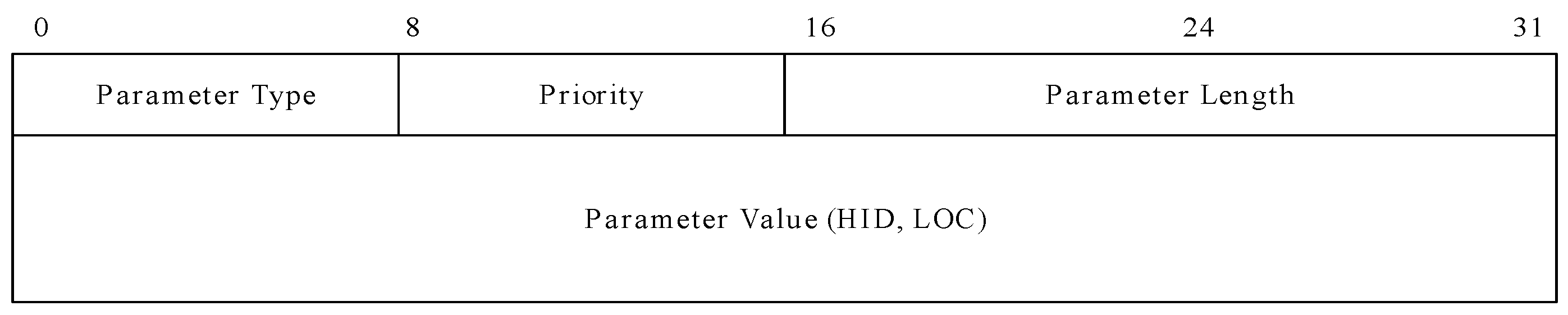
Each control message has a parameter, depending on the case. If there is a parameter in the control message, its type-length-value (TLV) format is as shown in Figure 13.
In the figure, the parameter type field is an encoding value of the parameter that has either an HID (0000 0000) or LOC (0000 0001). The priority field indicates the priority of this parameter when two or more parameters are contained. Specifically, “0” represents that no priority is given, and “1” represents the highest priority, whereas “255” is the lowest one. The parameter length field is the length of this parameter in bytes. Finally, the parameter value has an assigned variable size for the HID or LOC.
4. MOFI Implementation
We implemented the MOFI architecture using OpenFlow [16] and Click Modular Router [17] over a Linux platform. Next, we describe implementation details.
4.1. Host
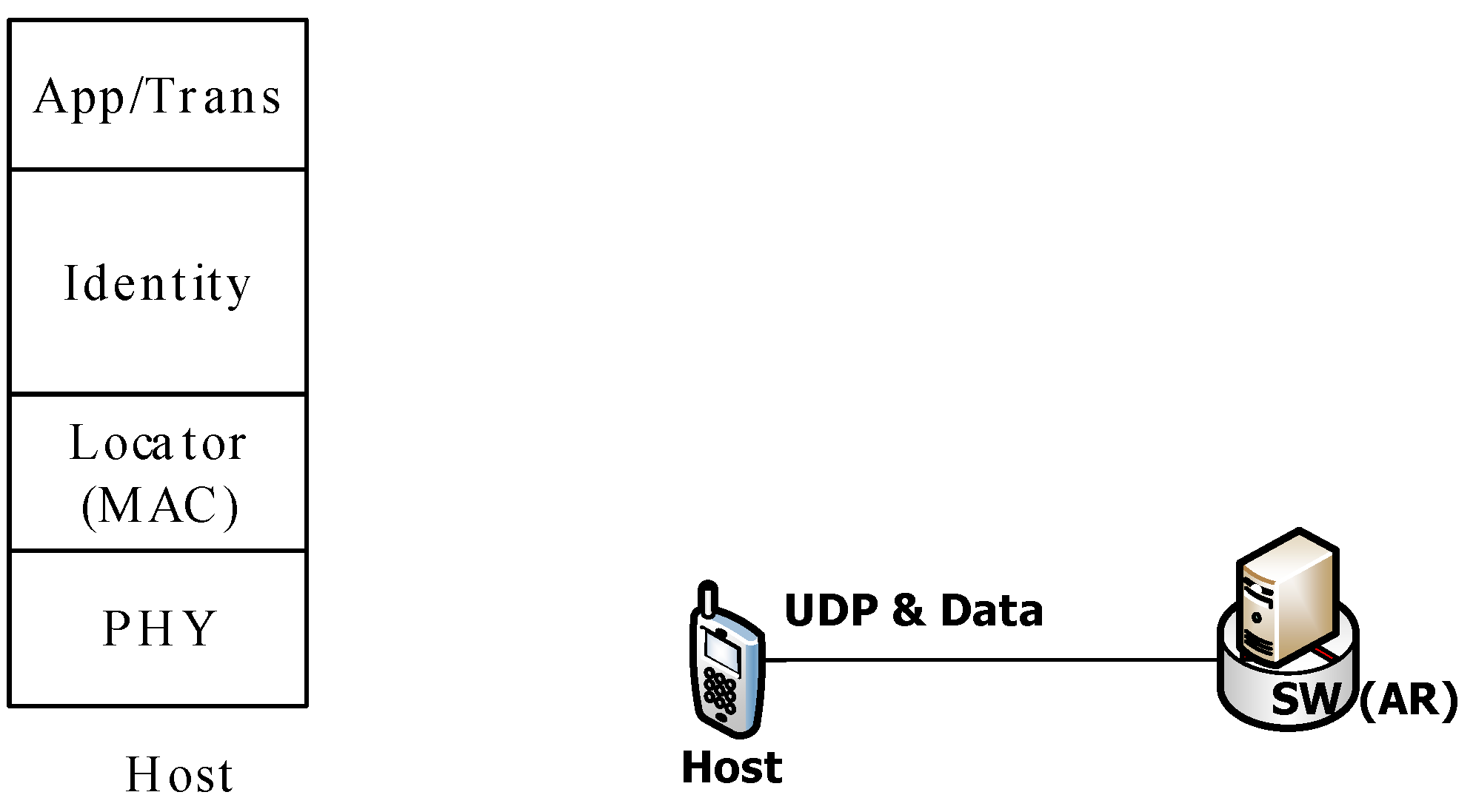
Firstly, we set up two hosts. One was a personal computer (PC)-based host and the other was an Android-based host. Due to the page limitations, however, we only describe the PC-based host in this article. Figure 14 shows a protocol stack and its connection with other entities.
In the figure, the host reuses the IPv6 protocol stack as an identity stack for backward compatibility. Thus, it is possible to use traditional socket interfaces for application programming. The locator field is used for packet delivery between a host and SW, which is used by a traditional MAC protocol stack. The host exchanges the data packet and HID binding operation with the SW. We implemented the HBR and HBA messages using raw socket APIs for the Internet Control Message Protocol version 6 (ICMPv6) protocol.
4.2. Switch
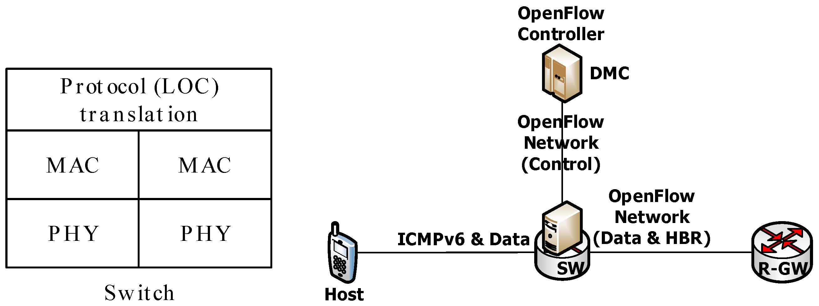
For the implementation of the SW, we used OpenFlow that was built on top of OpenVSwitch. Figure 15 shows the protocol stack of the SW and its connection with other entities.
SW translates a protocol (LOC) by changing the MAC header and uses an OpenFlow network. The SW exchanges the HID binding update operation and sends data packets to the R-GW through the OpenFlow network and performs the LOC query operation for the DMC through the OpenFlow control channel. In the OpenFlow network, the LOC query operation is replaced by the packet-in and packet-out messages.
4.3. R-GW
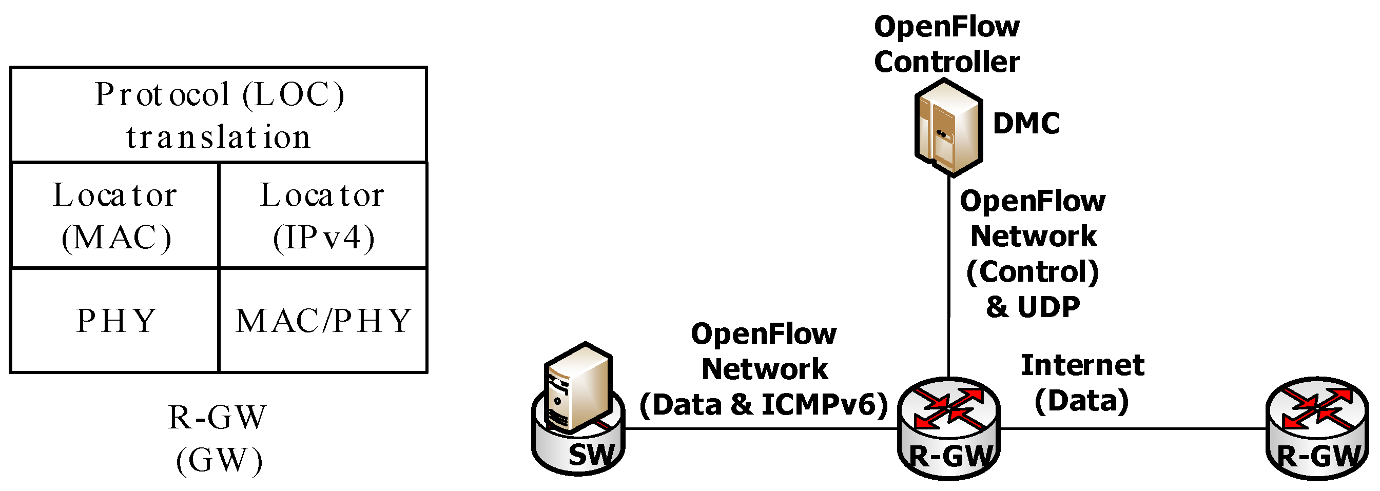
For the implementation of the R-GW, we used OpenFlow and Click Modular Router. Figure 16 shows the protocol stack of the R-GW and its connection with other entities.
The R-GW translates the protocol (LOC) by changing the MAC and an IPv4 headers and uses an OpenFlow network with the SW and DMC. The R-GW exchanges the HID binding update operation, sends data packets to the SW through the OpenFlow network, and performs the LOC query operation and HID binding update operation for the DMC through the UDP socket API. We used Click Modular Router to translate the LOC header of data packets, as well as to encapsulate and de-capsulate the HID binding update and LOC query message to a UDP packet.
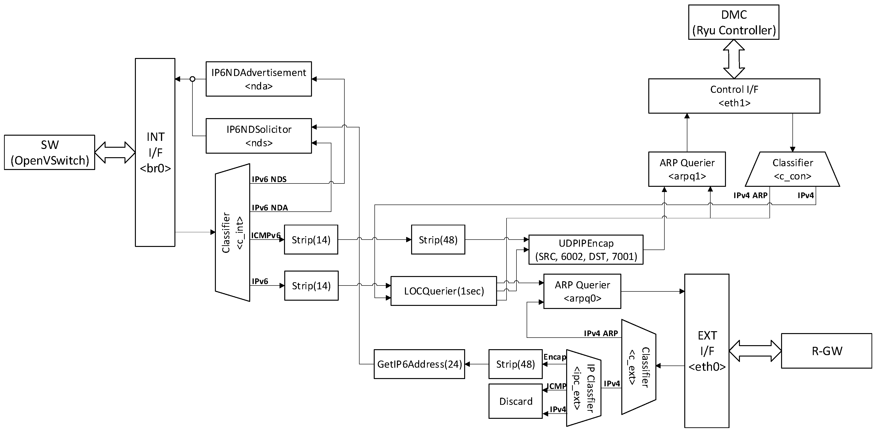
Figure 17 shows how a packet of the Click Modular Router at the R-GW is processed. In this figure, the R-GW has three network interfaces named INT I/F, Control I/F, and EXT I/F. INT I/F stands for an internal interface, which is connected to SWs via an OpenFlow data channel using an IPv6 network. Control I/F stands for a control interface, which is connected to the DMC through the OpenFlow control channel using the IPv4 network. Finally, EXT I/F stands for an external interface, which is connected to other R-GWs through the Internet. Upon receiving a packet from the SW, the INT I/F forwards it to the Classifier(), which classifies the packet to an IPv6 Neighbor Discovery Solicitation (IPv6 NDS), IPv6 Neighbor Advertisement (IPv6 NDA), IPv4, or IPv6 packet. An IPv6 NDS packet is forwarded to the IP6NDadvertisement element, while an IPv6 NDA packet is forwarded to the IP6NDSolicitor element. Then, they return to the INT I/F. An IPv4 packet is stripped to the MAC header and IPv4 header by the Strip(). After that, Click Modular Router adds an IP and a UDP header through UDPIPEncap(). To construct and encapsulate a MAC header, the packet is sent to ARPQuerier() and the DMC through the Control I/F.
An IPv6 packet is also stripped to the MAC header by Strip(). After that, if it is a data packet, it is forwarded to LOCQuerier() that is implemented for performing the LOC query operation and encapsulating the packet to IPv4 to forward another R-GW through the Internet. LOCQuerier() searches the DFC to find the LOC of RH. If there is no RH LOC at the DFC, it performs the LOC query operation for the DMC. To perform the LOC query operation, LOCQuerier() makes the LQR message and forwards it to UDPIPEncap() to construct the IP and UDP header. Then, the message is forwarded to the DMC through the Control I/F. DMC processes the LQR message and relays the LQA message to the R-GW through the Control I/F. The Control I/F forwards all receiving packets to the Classifier(), which classifies the packet into IPv4 ARP and others. The ARP packet is forwarded to ARPQuerier(). An LQA message is forwarded to LOCQuerier(). When receiving an LQA message, LOCQuerier() records the RH’s HID and the RH’s LOC to the DMC. At the same time, it constructs and encapsulates a MAC header. If the RH’s LOC exists at the DFC, the LOC query operation is omitted and LOCQuerier() is performed to construct and encapsulate a data packet. Then, the constructed packet is sent to ARPQuerier() and to another R-GW through the EXT I/F. Contrariwise, receiving a packet from another R-GW, EXT I/F forwards it to the Classifier(), which classifies the packet as IPv4 ARP and others. The ARP packet is forwarded to ARPQuerier(). Another packet is classified by the IPClassifier() into data, or ICMPv6 or IPv6 packets. The data packet is stripped to the encapsulated header at Strip(). Then, through GetIP6Address(), its IPv6 header is marked. To construct and encapsulate an MAC header, the packet is sent to the IP6DNSolicitor() element and it is sent to the SW through the INT I/F.
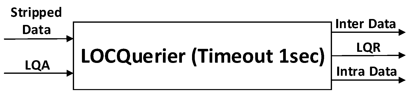
In the R-GW, we implemented LOCQuerier(), which maintains its DFC using cache memory, performs an LOC query operation, and encapsulates data packets. Figure 18 shows LOCQuerier()’s architecture.
To implement LOCQuerier(), we referred the ARPQuerier() element that handles all the data packets arriving at the R-GW. The argument timeout should be the timer of the DFC cache expiration. There are two input ports and three output ports. Packets arriving at input 0 should be stripped data packets and must have a destination HID. If a DFC cache for the destination HID already exists, the data packets are sent to the inter-domain or intra-domain in accordance with their destination HID. If a DFC cache does not exist, data packets are saved and an LQR message is sent instead. Then, an LQA message should include the LOC of the destination. At the same time, a DFC cache is created, and it saves HID–LOC mapping information. The DFC cache is automatically deleted after one second because of the expiration timeout.
For inter-domain communications, a data packet is encapsulated by LOCQuerier() into an IPv4 header and is encapsulated by ARPQuerier() into a MAC header.
4.4. DMC
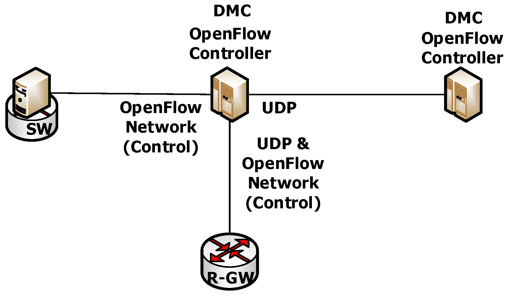
For the implementation of the DMC, we used OpenFlow, which uses a Ryu controller because of the IPv6 support. Figure 19 shows the connection of the DMC with other entities.
DMC exchanges an HID binding update and an LOC query operation to the R-GW using UDP through an OpenFlow control channel and an LOC query operation to the SW through an OpenFlow control channel, which is located in the intra-domain. Within the DMC, they exchange an HID binding update and an LOC query operation through the UDP. If the DMC receives an HBR/LQR, it determines the destination of the packet, which may be itself or another DMC. Then, the HBR/LQR message is forwarded to the determined destination. In the HBR message’s case, the DMC updates its SMR table and creates an HBA message to notify the result of the HBR message. In the case of an LQR message, the DMC searches an SMR table to find the HID–LOC mapping information and creates an LQA message containing the HID–LOC mapping information. At that time, the DMC sends the LQA messages in response to the LQR message.
In MOFI, we assigned OpenFlow entities to the MOFI register and cache because they perform the same role in a network. Table 4 summarizes the entity mapping between OpenFlow and the MOFI implementation.
The flow table of the Ryu controller is mapped to the DMC’s LMR and the flow table of OpenVSwitch is mapped to the DFC of the SW. In the OpenFlow network, the packet-in, packet-out, and flow-mod message set up the route to deliver a data path and, hence, we use these messages to perform the LOC query operation in the MOFI architecture. Through this process, we can reduce the consumption of network resources by avoiding duplicated operations, as well as by reducing the programming burden.
5. MOFI Experimentations on EU–Korea Testbed
The interconnection of Europe and South Korea takes advantage of the GÉANT [19] network in Europe, while the respective KOREN [20] and KREONET [21] are used in South Korea. The GÉANT and KOREN/KREONET are interconnected via TEIN3 [22] and TEIN4 [23].
The first pilot evaluated in this paper was an identity-based communication. Physically distributed sensors across European countries continuously generate data and then they are streamed to South Korea. Because sensors are highly mobile (e.g., portable sensors attached to moving hosts), they cannot be identified using the traditional IP addressing mechanism. The communications between Europe and South Korea sites are achieved using a host identifier, while IP addresses are only used in an inter-domain area. When a host enters the range of a new switch (SW), the sensor data are forwarded to the new SW by a location management function operated by OpenFlow controller. Each host is able to start a sensor data streaming service with every host, whether located in Europe or South Korea, where the sensor data can be forwarded constantly and seamlessly. This service is orchestrated by another OpenFlow controller. In this scenario, the OpenFlow controller is named a distributed mobility controller (DMC).
Another pilot was a content-based communication. In this scenario, a content-based architecture was implemented using SDN technologies on top of Europe and South Korea testbeds. The utilized resources were interconnected including Layer 2 intercontinental virtual links, based on GEANT–GLORAID–KREONET services. Wireless devices laying in the Europe testbed are connected to a content-based network in South Korea, and content identifiers are used instead of IPs. The goal of this innovation is to use identifiers only to specify the content itself, unlike an IP address which specifies the location of a content. Each content is placed on multiple sides of the South Korea testbed. The target of the content-based architecture follows the content from the most appropriate side to the requesting wireless device, while the streaming over the Europe wireless mesh is based on a backpressure routing scheme.
In the following section, we discuss the identity-based communication scenario that uses the MOFI architecture in detail. Then, we evaluate the MOFI architecture by constructing the testbeds in Europe and South Korea.
5.1. Testbed Configuration
In the discussion below, we describe the experiments conducted over the testbed.
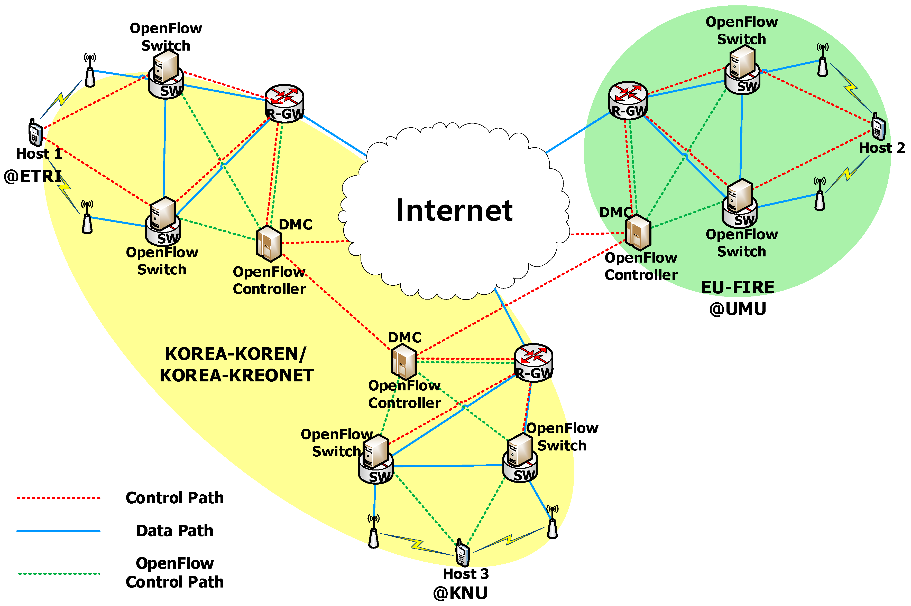
Figure 20 shows testbed configurations for the experiments. There were three network domains as follows: one was located at KNU (Kyungpook National University), another was located at ETRI (Electronics and Telecommunications Research Institute), and the last one was located at UMU (Universidad de Murcia). On the Korea side, KNU and ETRI sites are connected via KOREN [20] and KREONET [21]. On the EU side, UMU uses the GAIA network. Korea and the EU are connected via TEIN4 [23]. For the experiments, we used Ubuntu 12.04 and Linux kernel 3.5.0.23-generic version. To support the MOFI HID, we used OpenFlow 1.3 version, OpenVswitch, and Ryu controller. Each domain has a unique AS (Autonomous System) number. KNU was assigned to 0 × 2744, and ETRI was assigned to 0 × 0EA4. However, because the UMU site was not assigned yet, it used ETRI’s AS number temporarily.
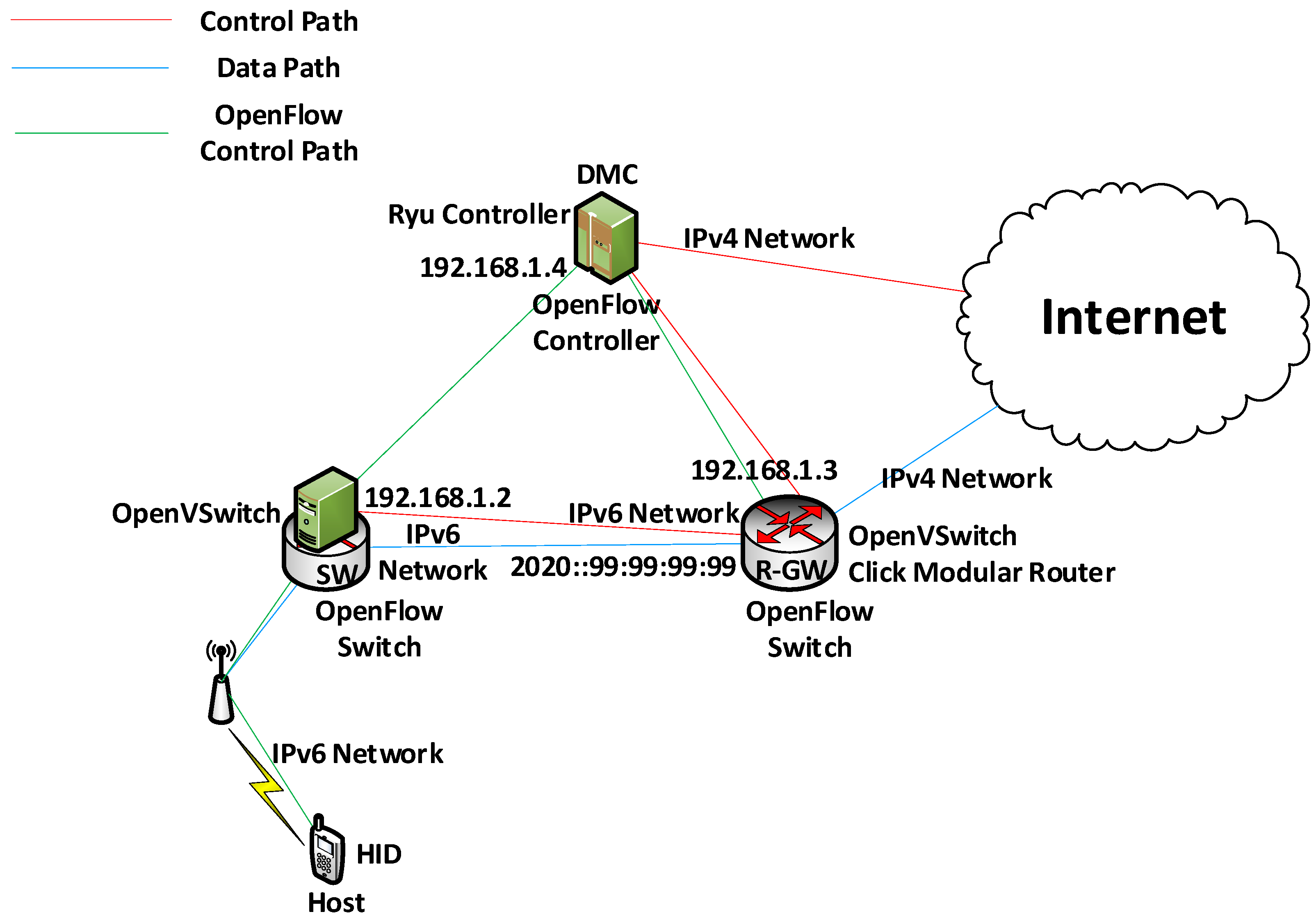
Each domain had the same intra-domain network architecture except for hardware specifications, as shown in Figure 21. The host had a globally unique HID that was connected to the SW through an IPv6 network to deliver data packets and HID binding messages. To support a wireless network, we used an access point, and the SW also supported multiple hosts. The SW used OpenVSwitch and had three interfaces. The first interface was the OpenFlow controller of this domain, which was connected to the DMC. It used an IPv4 network to transmit an OpenFlow control message instead of an LOC query operation, in which the interface used a 192.168.1.2 IP address. Otherwise, the other two interfaces used an IPv6 network to forward data packets and HID binding messages to other entities. These interfaces did not have an IPv6 address because they configured the OpenFlow network. One interface was connected to the host, while another one was connected to the R-GW to communicate between other domain hosts and to perform an HID binding operation, which used a MAC header as the LOC. The R-GW used OpenVSwitch and Click Modular Router and also had three interfaces. One was connected to the DMC and used an IPv4 network to transmit OpenFlow control messages, HID binding messages, and LOC query messages. It used an IP address of 192.168.1.3. To perform an HID binding operation and an LOC query operation, it used a Click Modular router to translate HID binding messages and to send LOC query messages. The other interface used an IPv6 network to transmit the data packets and HID binding messages to the SW, the interface of which had an IPv6 address of 2020::99:99:99:99 as a default gateway. The last interface used a public IPv4 network to transmit data packets to other domains. These communications could be achieved by the LOC translation using the Click Modular router. The DMC had two interfaces. One was connected to the SW and R-GW to transmit OpenFlow control messages, HID binding messages, and LOC query messages. The other was connected to other DMCs belonging in a different domain. Thus, it used a public IPv4 network. To transmit HID binding messages and LOC query messages, the DMC used a UDP socket.
To evaluate our MOFI implementation, each domain had different testbed configurations. KNU and UMU sites consisted of PCs as the SW, R-GW, and DMC. Otherwise, the ETRI site consisted of blade servers to construct the SW, R-GW, and DMC. The hosts located at KNU and ETRI used a laptop-based host. On the other hand, UMU used a PC-based host. In addition, ETRI use smartphone-, tablet-, and TV-based hosts to demonstrate an N-Screen scenario.
5.2. Validation of MOFI Implementations
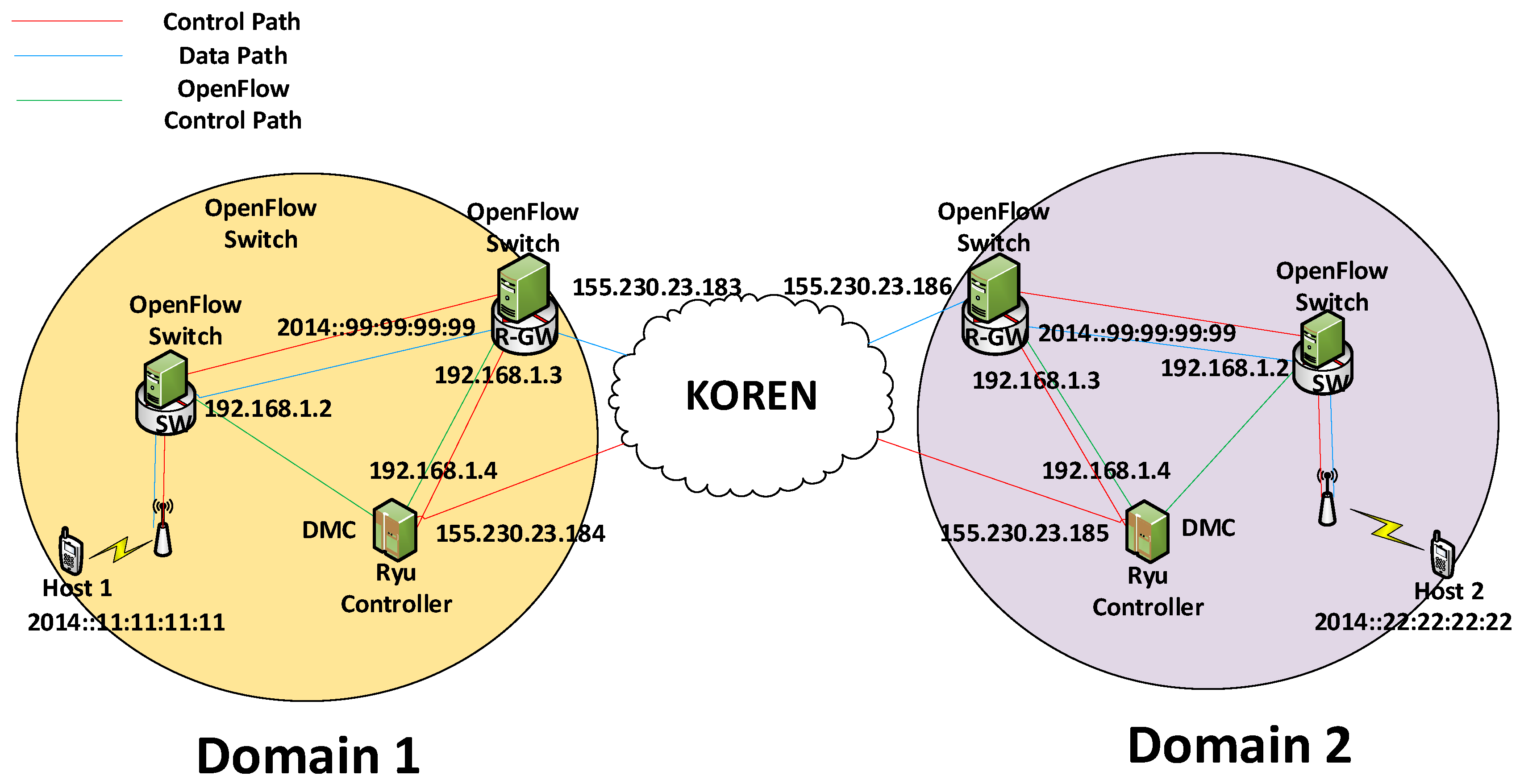
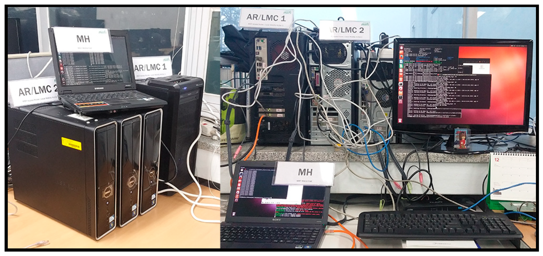
For the validation of MOFI, we constructed a small testbed locally located at KNU and experimented on the implemented MOFI architecture. Some test scenarios were used for the evaluation. Firstly, Host 1 and Host 2 were attached to each domain. Two applications were used for the validation. One was a UDP echo server/client. Another was a video streaming service. In the UDP echo server/client, Host 1 was a UDP echo server and Host 2 was a UDP echo client. For the streaming service, Host 2 begins receiving the video data traffic from Host 1. To validate the MOFI implementation, we captured the data and control packets that flew in the testbed network using Wireshark [24]. Figure 22 shows the testbed configuration for validation. There were two domains inter-connected by the KOREN backbone network.
In the testbed network, Host 1 was a video streaming server and Host 2 was a VLC player [25]. Host 1 and 2 used 2014::11:11:11:11 and 2014::22:22:22:22 for their HIDs, respectively. As for the LOC, an MAC address was used for the intra-domain communication. On the other hand, a public IPv4 address (155.230.23.183 and 155.230.23.186) was used as the LOC for inter-domain communications. For an OpenFlow control path, we used a private IPv4 address (192.168.1.x). On the other hand, the control path between DMCs used public IPv4 addresses (155.230.23.184 and 155.230.23.185). In the figure, the control path represents the route used for HID–LOC binding and LOC update operations in the MOFI architecture. Figure 23 shows a snapshot of the testbed described in Figure 22.
With this testbed, we validated our MOFI implementation. In the figure, the left side is domain 1 and the right side is domain 2. They had similar network configurations with one mobile host (MH), SW, R-GW, and DMC in each domain. R-GWs and DMCs were interconnected by the KOREN network for inter-domain communications. Each domain was an OpenFlow network.
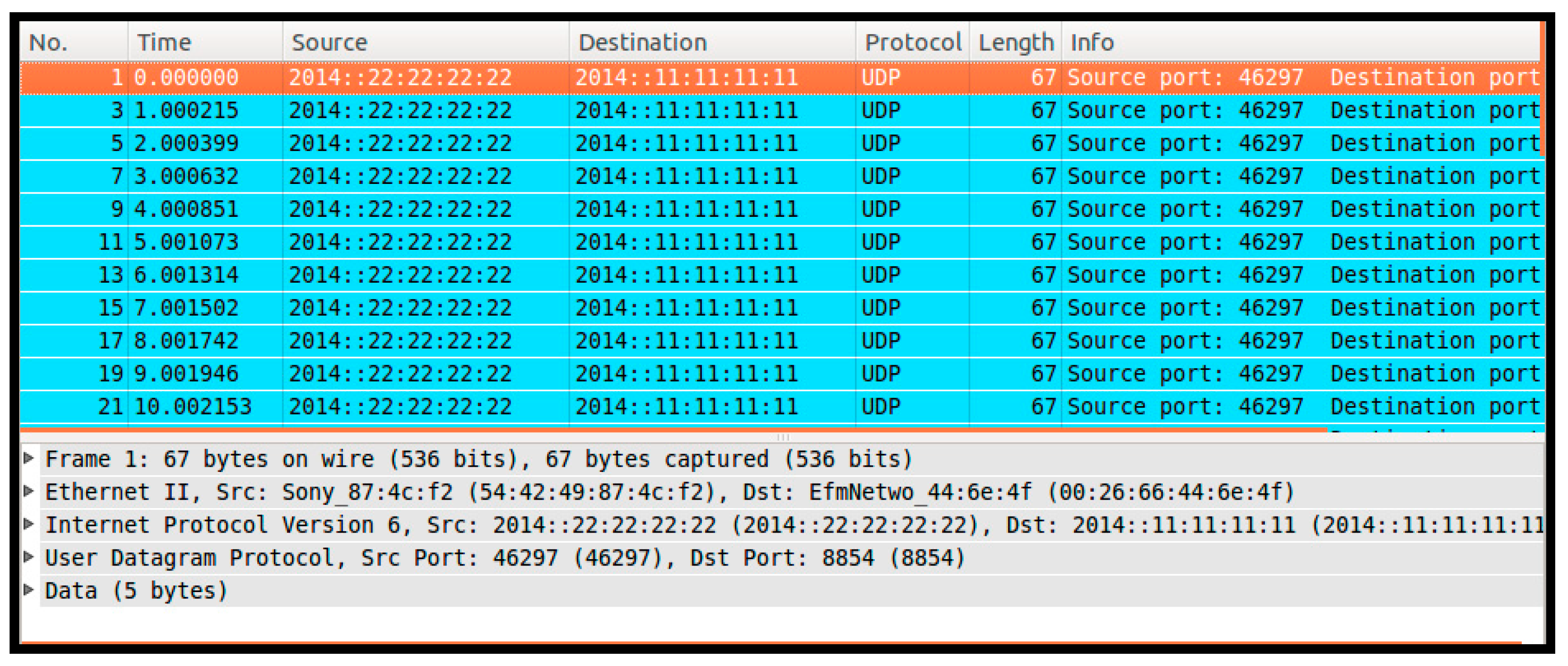
Figure 24 shows packet capturing results flowing from Host 2 at domain 2. In this figure, Host 1 and 2 use 2014::11:11:11:11 and 2014::22:22:22:22. The HID header is represented as an IPv6 header because Wireshark does not support the MOFI architecture. However, we can know that the MOFI HID header and IPv6 header are interoperable between each other at the application layer, and they use a similar packet format. Moreover, we can know that the application program is compatible with both the MOFI architecture and an IPv6 network.
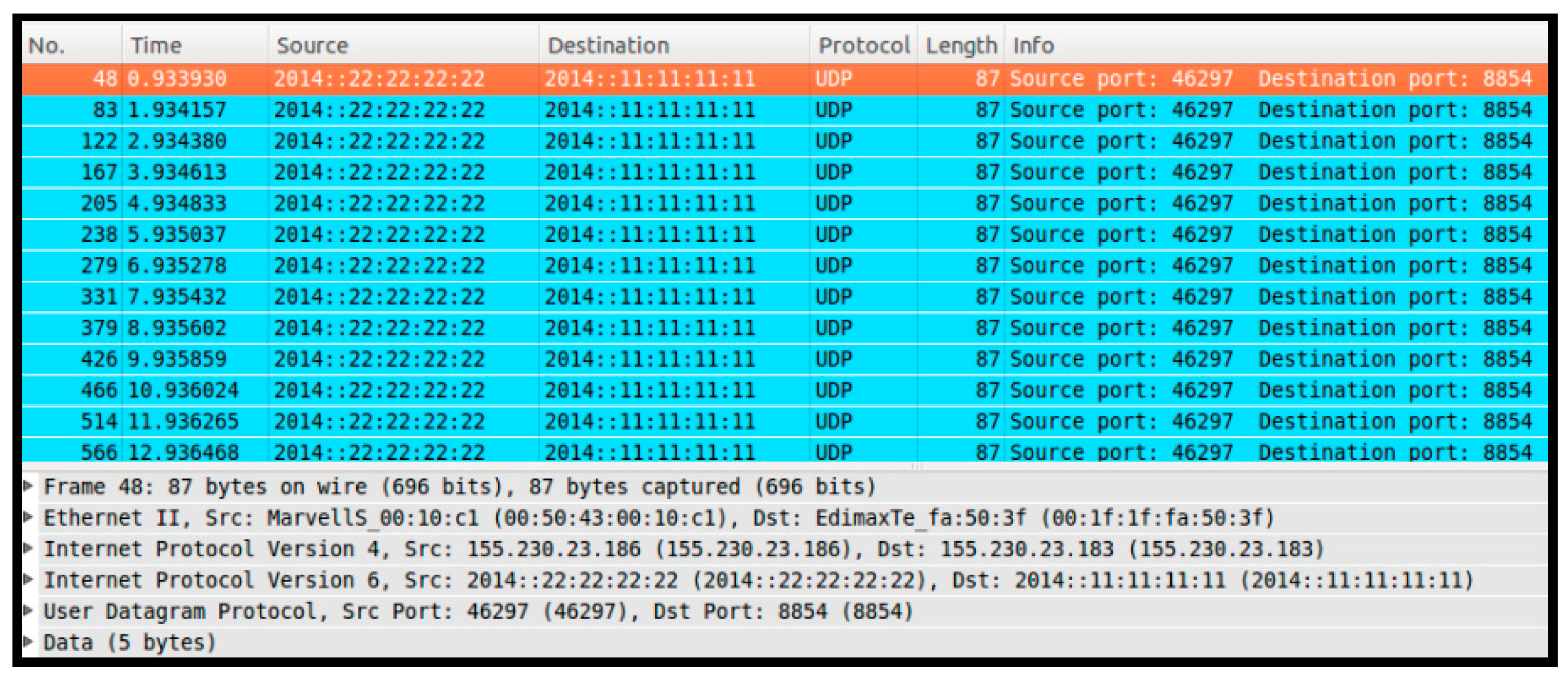
Figure 25 shows the packet capturing result flowing from the R-GW of domain 1 to the R-GW of domain 2. In this figure, we can see that LOCs were translated along the path since the Click Modular Router of R-GW performed the protocol translation by encapsulating the LOC header. While MAC and IPv6 headers were used as LOC and HID, respectively, R-GWs used 155.230.23.186 and 155.230.23.183 as LOCs (public IP addresses). Furthermore, the packet size was larger than the Pv4 header size (20 bytes) because R-GW encapsulated an IPv4 header into an LOC header. We can also see that a MAC header was successfully translated. In the meantime, HIDs of Host 1 and Host 2 did not change during the data delivery.
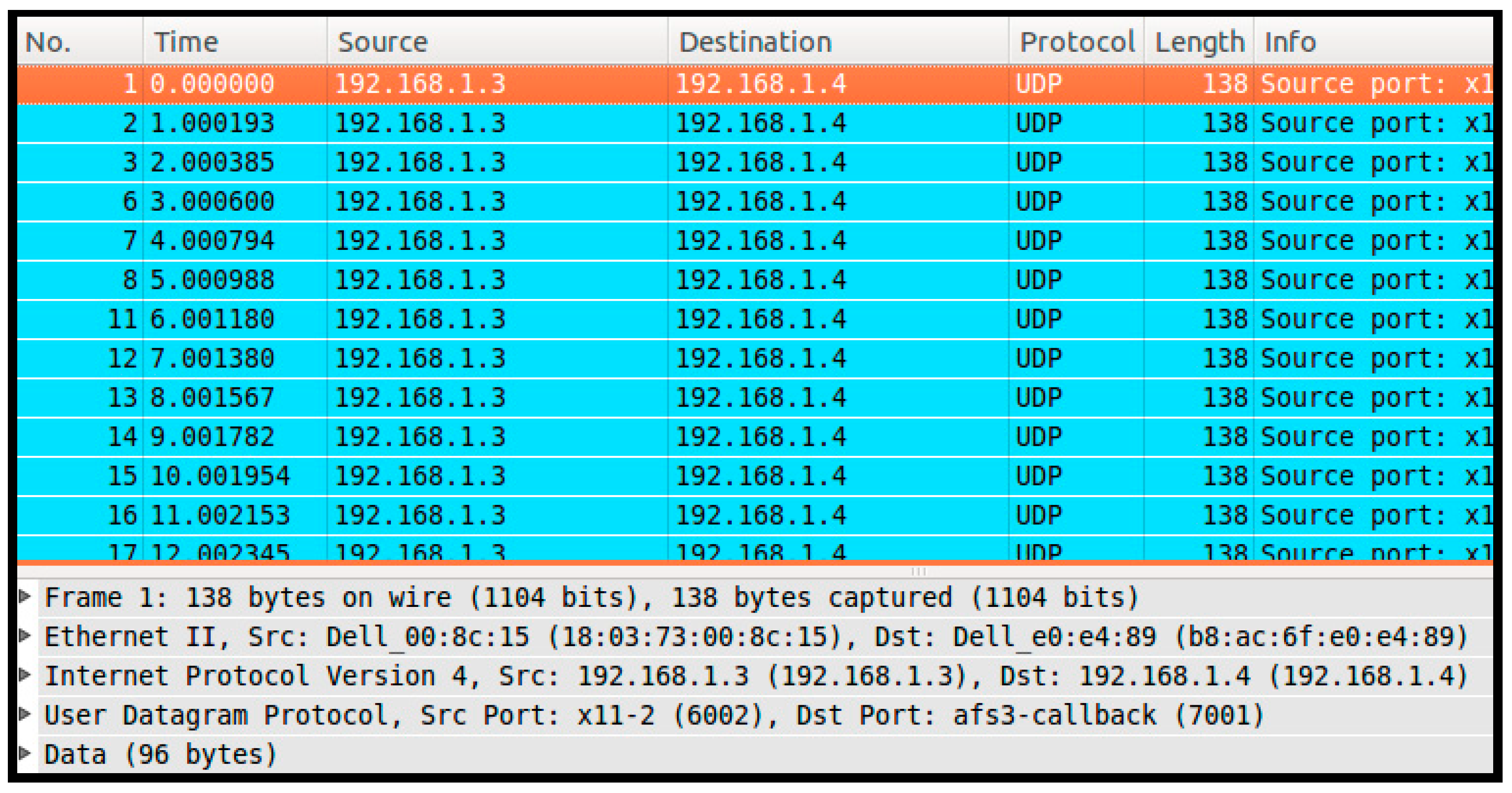
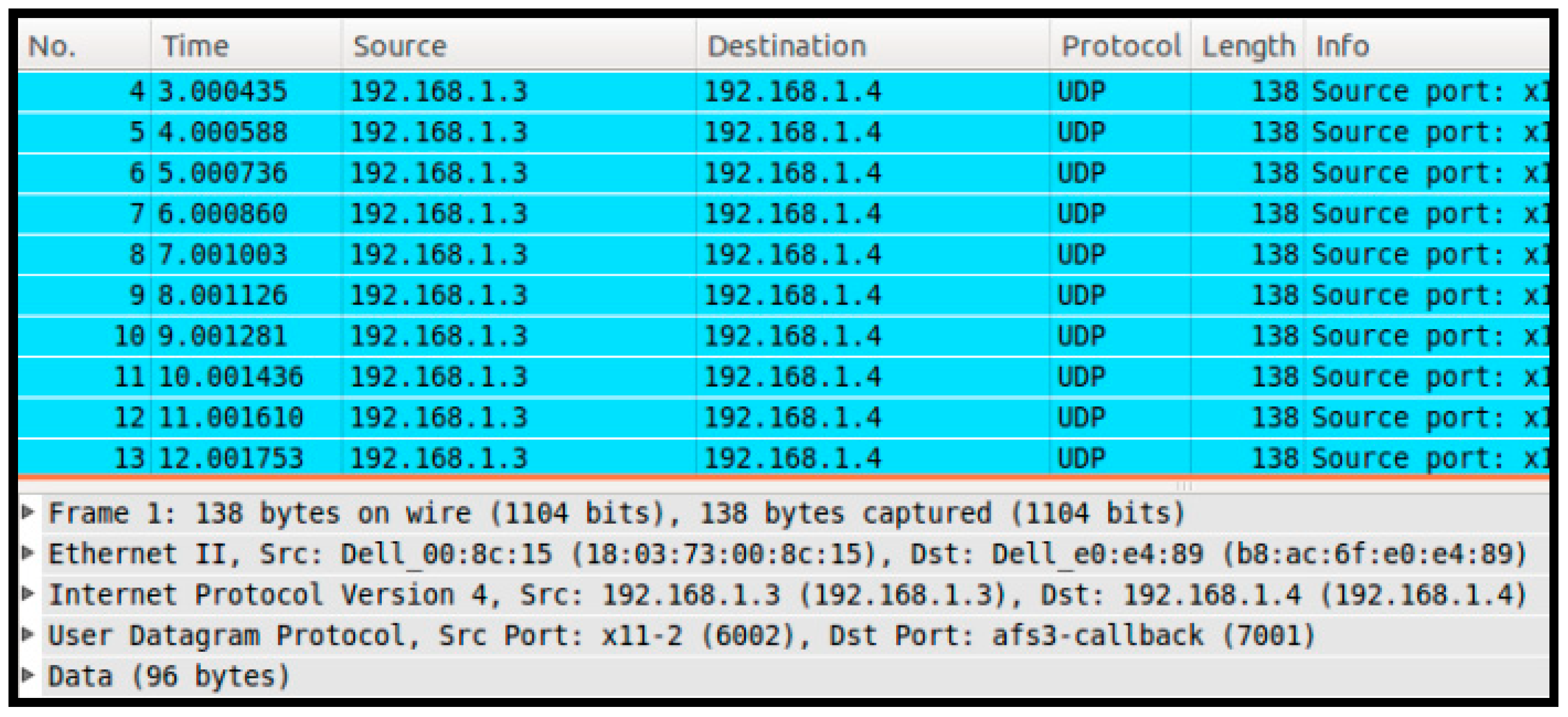
To validate the control plane operation, we used Wireshark to capture control packets at the R-GW and DMC. Figure 26 shows the packet capturing result for the LOC query operations between the R-GW and DMC.
In the figure, we can see that the source address and port number was 192.168.1.3:6002, and the destination address and port number was 192.168.1.4:7001. Then, the message used UDP. This means that the messages were generated by the Click Modular Router of the R-GW for the LOC query operation, while the OpenFlow control messages used transmission control protocol (TCP). The packet involved LQR messages to query the LOC of the RH to the designated DMC of the RH.
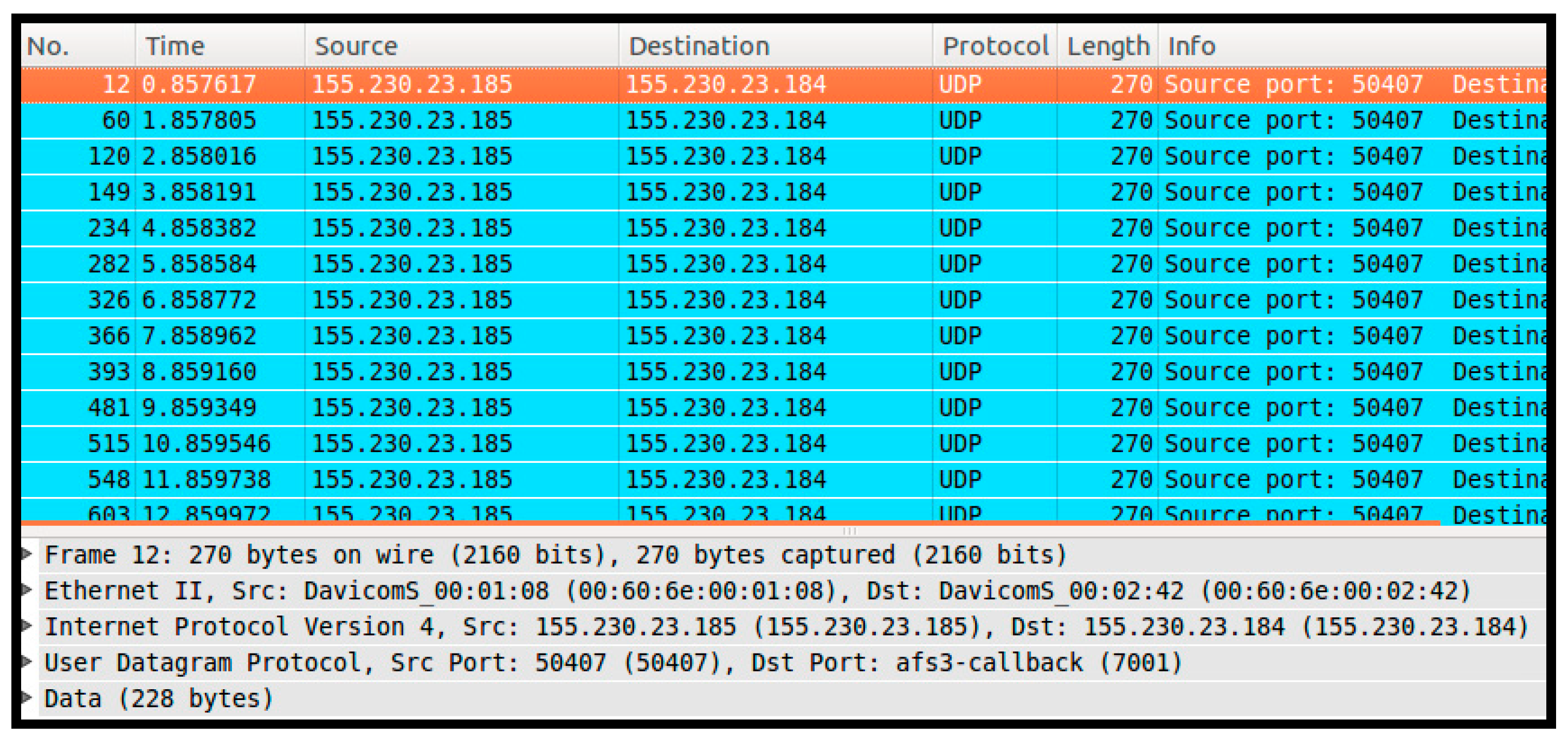
Figure 27 shows the packet capturing result between DMCs. From the figure, a packet is transmitted from the DMC of domain 2 (155.230.23.185) to the DMC of domain 1 (155.230.23.184). We realized that all the packets were LQA messages because Host 1 sent data packets to Host 2 in the test scenario and, thus, the LOC query operation was performed for the DMC of domain 1 to the DMC of domain 2. Moreover, because LQA messages had four parameters to store the HID and LOC of the SH and RH, they were larger than other control messages. The actual packet size was the biggest when compared with other control packets shown in Figure 26, Figure 28, and Figure 29.
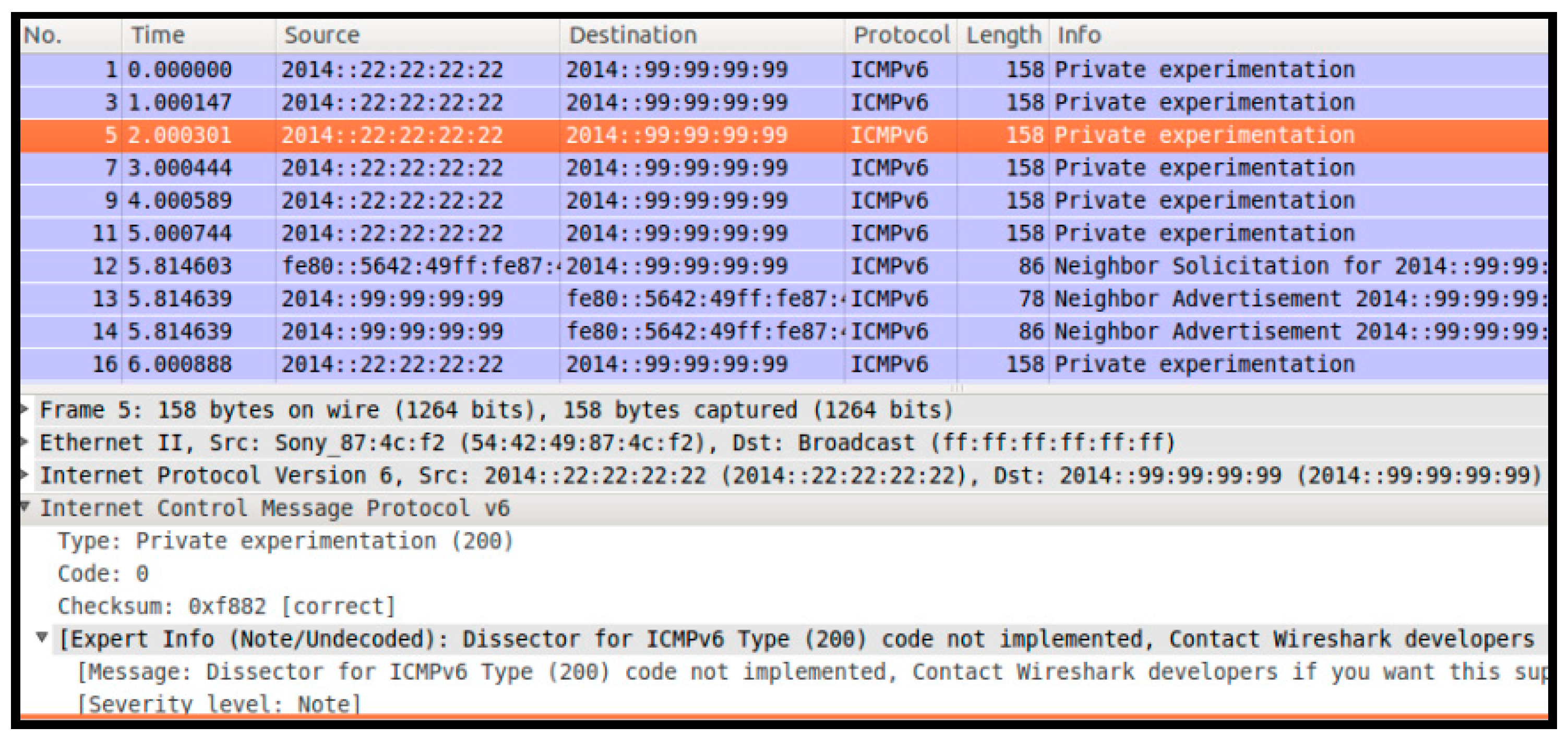
Figure 28 shows the packet capturing result for the HID binding operation of Host 2. In the figure, we can see that the destination address was 2014::99:99:99:99. This was because the host could not know the destination address to perform the HID binding update operation when attached to a new network. Thus, we supposed that all R-GWs should have a bridge interface (br0) to be the destination of the HID binding update message, for which the address was 2014::99:99:99:99. To perform the HID binding operation, we implemented an Internet Control Message Protocol version 6 (ICMPv6) message using raw socket APIs, because ICMPv6 has several options such as the neighbor discovery protocol (NDP). Thus, we concluded the ICMPv6 message to perform the HID binding operation. An ICMPv6 message was extended to perform the HID binding operation between a host and the R-GW. For this purpose, we assigned the type as 200, which means private experimentation, and we implemented an ICMP message body as an HBR/HBA message. Because of using ICMPv6 and supporting the backward compatibility between HID and IPv6, we were able to implement the MOFI architecture while still allowing the use of the existing IPv6 network and IPv6 applications.
Figure 29 shows the packet capturing result between the R-GW and the DMC for the HID binding operation of Host 1. From the figure, we can see the source address and its port. Then, the messages used UDP for the transmission. Unlike LQR messages, these messages were not generated by the Click Modular Router of the R-GW. Upon receiving HBR messages from the Host, they were encapsulated by the Click Modular Router of R-GW for the HID binding operation and they were forwarded to their own DMC.
5.3. N-Screen Scenario
We chose an N-Screen application to demonstrate the superiority of the MOFI architecture since this service scenario occurs frequently and it shows the service mobility scenario. When a user returns home from outside, the video still streams to the smart phone. At the time a user enters the house, various screens are discovered, for example, television (TV), tablet, etc. These screens perform negotiation processes with each other and share the HID. At this point, the smart phone selects another destination screen that will receive the ongoing video stream. Since the MOFI GW maintains its mapping table that maps each screen’s HID to its LOC, the selected screen is assigned the same HID and the video is directly forwarded to the desired screen through the GW.
For this purpose, we implemented the N-Screen application based on an Android system and constructed two domains at the ETRI site. There are two domains that are interconnected by the KREONET backbone network. Furthermore, we used one domain of the KNU site for the server side of the N-Screen scenario; the video stream initiated a server located at KNU and video clients located at ETRI, and we could observe the media data being streamed through the network, which was inter-connected by the EU–Korea network.
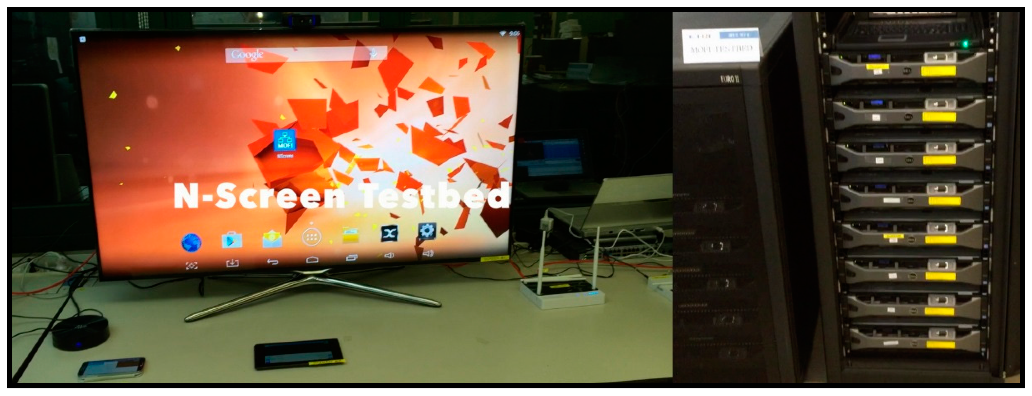
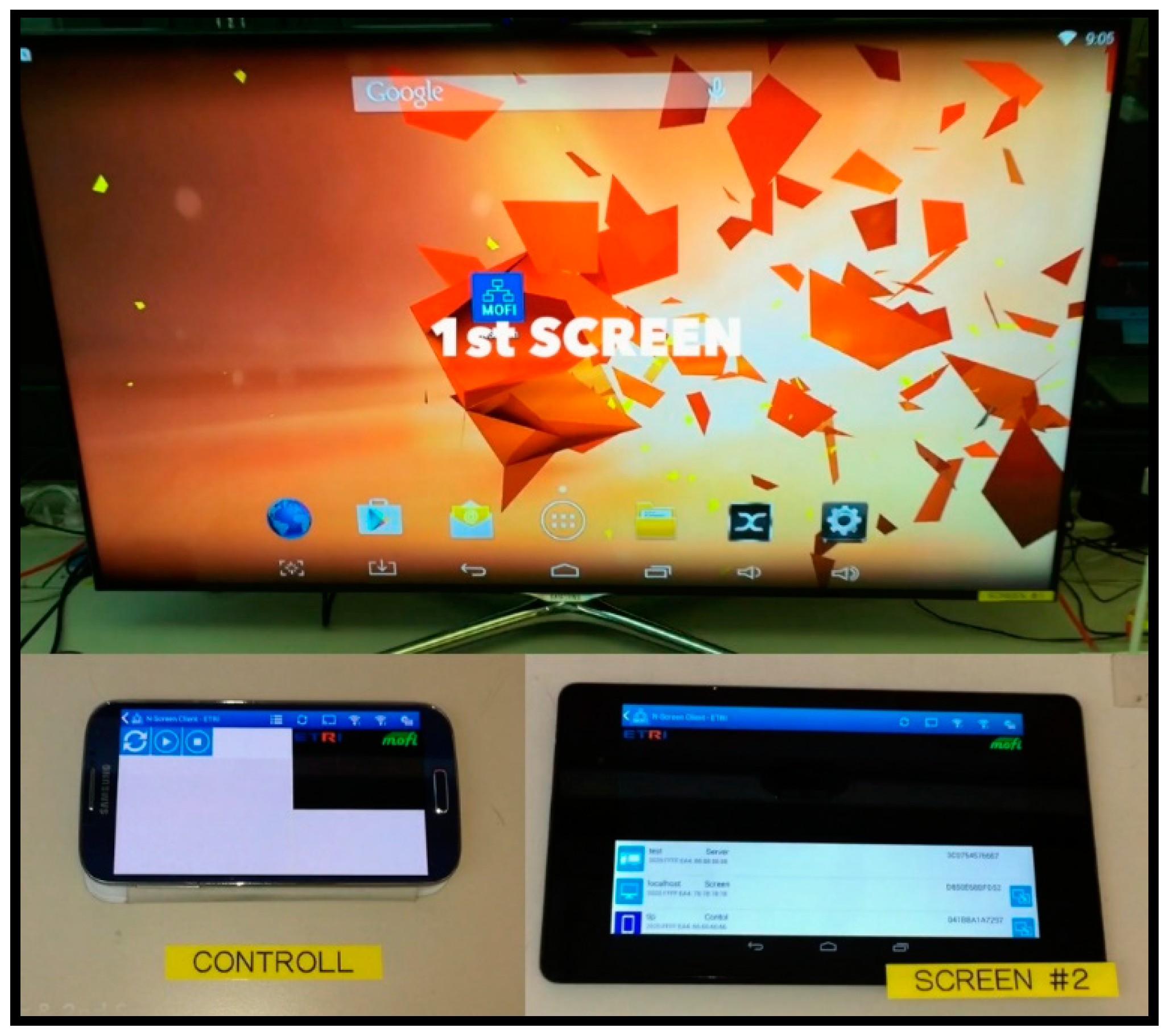
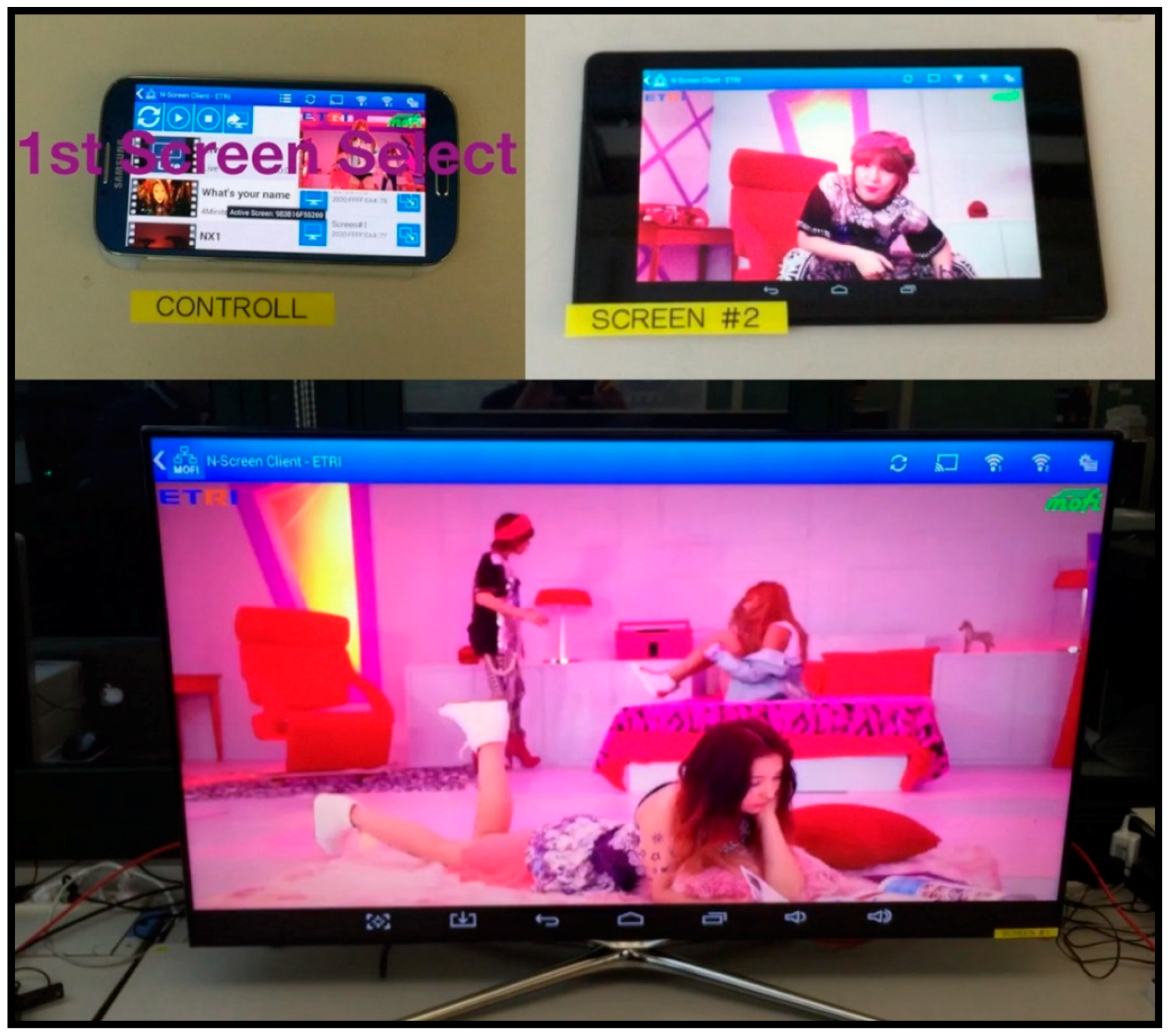
Figure 30 shows the testbed for the N-Screen scenario at the ETRI site. There were three screens as follows: the first one was a controller, and the others were screens. There were two screen types for the demonstration. One was a TV using a Universal Serial Bus (USB) dongle based on Android, and the other was a tablet. The controller used the smartphone. For the experiment, Figure 31 shows the controller and two screens.
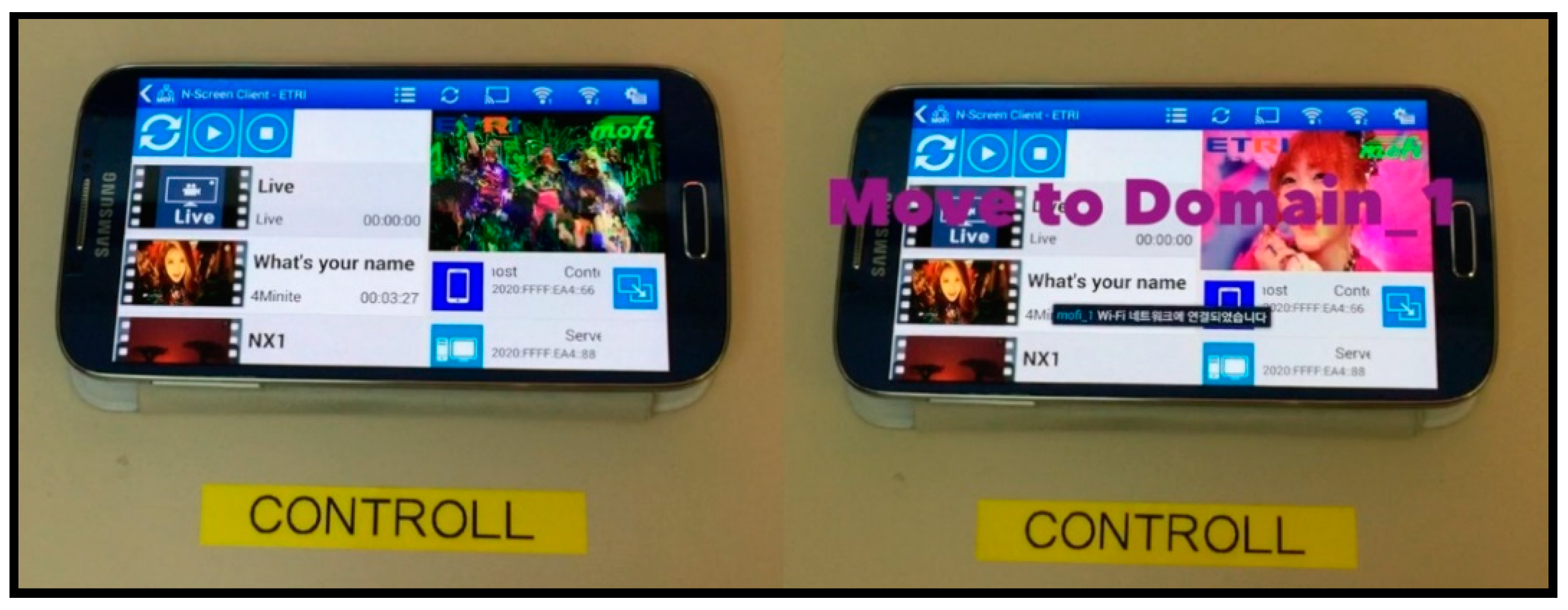
Firstly, we demonstrated the handover scenario from domain 2 to domain 1. For this scenario, we used the controller as a host device. In this service mobility scenario, the controller was already connected to the MOFI domain 2. Figure 32 shows the inter-domain handover of the controller.
From the figure, the left side shows a screenshot before the handover and the right side shows a screenshot after the handover. We implemented that the user interface of controller can choose one of two access points connected to each domain. In this experiment, we carried out the handover by selecting another access point. Even though we observed handover delay, the handover scenario was successfully performed.
Next, we demonstrated the N-Screen scenario. Using the controller, we selected a screen to play the movie clip. Figure 33 shows screenshots of our N-Screen experiment. The registered screens at the controller are displayed in a list, and a user can then choose one to play. Through the experiment, we could see that a movie clip was properly played on the screen when it was selected. Since screens 1 and 2 were connected to the same domain, it was possible to verify intra-domain handover through this scenario.
6. Conclusions
In this article, we presented a new mobility management architecture for a future mobile network. The new architecture features the separation of data and control planes, as well as a novel distributed HID–LOC mapping control. We implemented the architecture using OpenFlow and Click Modular Router over a Linux platform and tested the implemented architecture over the EU–Korea testbed network for validation.
To evaluate the proposed architecture, we implemented OpenFlow and Click Modular Router over a Linux platform, and then we validated it using a local testbed. Moreover, we performed the evaluation over an internationally configured EU–Korea testbed network. In particular, we operated the realistic service scenario over the EU–Korea testbed network using an N-Screen scenario. Using various screens for streaming a movie clip, the mobility and the service scenario of the proposed architecture were shown. In the intra-domain mobility event (changing the screen using a controller), there was no observable impact on the streaming session. On the other hand, in the inter-domain mobility event (moving to another domain), although the LOC changed, the HID was able to communicate constantly, and it could be confirmed that there was slight handover latency due to LOC change. However, since the service uses ID-based communication, there is no need to disconnect the service or make a new connection for the service. In order to provide a seamless streaming service, the MOFI control plane performs mapping of each host’s HID to a specific LOC, and it updates this mapping information and creates the flows that will forward the traffic to the new location. After updating the mapping information, streaming data are forwarded to the new domain network to which the client is now attached.
In particular, the proposed architecture could provide mobility management without any modification of the current Internet architecture. Furthermore, we showed that the implemented architecture can support backward compatibilities with current IPv6 applications and Internet Protocol networks.
As a future research direction, we will consider integrating security and mobility functionality into the proposed architecture. Because our first goal was to provide an architecture that functions with basic network features, we focused on designing and evaluating the basic architecture. As future research directions, we will firstly address security and mobility issues that were not fully considered in the current design. Also, we will evaluate our architecture with various user scenarios, because Internet services are becoming more dynamic and diverse. Finally, we plan to integrate the concept of virtualization in the next MOFI architecture.
Author Contributions
J.-I.K. wrote the initial manuscript; N.-J.C. and T.-W.Y. performed the testbed experimentation; H.J. conducted the performance analysis; Y.-W.K. and S.-J.K. revised the manuscript.
Acknowledgments
This research was supported by Basic Science Research Program through the National Research Foundation of MoE (NRF-2017R1D1A3B03032156).
Conflicts of Interest
The authors declare no conflict of interest.
References
- Feldmann, A. Internet Clean-Slate Design: What and Why? ACM SIGCOMM Comput. Commun. Rev. 2007, 37, 59–64. [Google Scholar] [CrossRef]
- Kim, J.I.; Jung, H.; Koh, S.J. Mobile Oriented Future Internet (MOFI): Architectural Design and Implementations. ETRI J. 2013, 35, 666–676. [Google Scholar] [CrossRef]
- Network Simulator 3. Available online: https://www.nsnam.org/ (accessed on 18 March 2019).
- OPNET. Available online: http://www.riverbed.com/products/performance-management-control/opnet.html (accessed on 18 March 2019).
- OpenFlow. Available online: http://flowgrammable.org/sdn/openflow/ (accessed on 18 March 2019).
- Kohler, E.; Robert, M.; Chen, B.; Jannotti, J.; Kaashoek, M.F. The Click modular router. ACM Trans. Comput. Syst. 2000, 18, 263–297. [Google Scholar] [CrossRef]
- Perkins, C.; Johnson, D.; Arkko, J. Mobility Support in IPv6. IETF RFC 6275. Available online: https://tools.ietf.org/html/rfc6275 (accessed on 18 March 2019).
- Gundavelli, S.; Leung, K.; Devarapalli, V.; Chowdhury, K.; Patil, B. Proxy Mobile IPv6. IETF RFC 5213. Available online: https://tools.ietf.org/html/rfc5213 (accessed on 18 March 2019).
- Correia, L.M.; Abramowicz, H.; Johnsson, M.; Wünstel, K. Architecture and Design for the Future Internet: 4WARD Project; Springer Science & Business Media: Berlin, Germany, 2011. [Google Scholar]
- Lindgren, A. Efficient content-distribution in a hybrid opportunistic network. In Proceedings of the IEEE Consumer Communications and Networking Conference, Las Vegas, NV, USA, 9–12 January 2011. [Google Scholar]
- Ahlgren, B.; D’Ambrosio, M.; Marchisio, M.; Marsh, I.; Dannewitz, C.; Ohlman, B.; Pentikousis, K.; Strandberg, O.; Rembarz, R.; Vercellone, V. Design considerations for a network of information. In Proceedings of the 2008 ACM CoNEXT Conference (CoNEXT’08), Madrid, Spain, 9–12 December 2008. [Google Scholar]
- Future Internet Design (FIND). Available online: http://www.nets-find.net (accessed on 18 March 2019).
- Mobility First: Future Internet Architecture. Available online: http://mobilityfirst.winlab.rutgers.edu/ (accessed on 18 March 2019).
- Raychaudhuri, D.; Nagaraja, K.; Venkataramani, A. MobilityFirst: A robust and trustworthy mobility-centric architecture for the future Internet. ACM SIGCOMM Comput. Commun. Rev. 2012, 16, 2–13. [Google Scholar] [CrossRef]
- Seskar, I.; Nagaraja, K.; Nelson, S.; Raychaudhuri, D. MobilityFirst future internet architecture project. In Proceedings of the 7th Asian Internet Engineering Conference (AINTEC’11), Bangkok, Thailand, 9–11 November 2011. [Google Scholar]
- Global Environment for Network Innovations (GENI). Available online: https://www.geni.net/ (accessed on 18 March 2019).
- Zhang, L.; Afanasyev, A.; Burke, J.; Jacobson, V.; Crowley, P.; Papadopoulos, C.; Wang, L.; Zhang, B. Named data networking. ACM SIGCOMM Comput. Commun. Rev. 2014, 44, 66–73. [Google Scholar] [CrossRef]
- Autonomous System (AS) Numbers. Available online: http://www.iana.org/assignments/as-numbers/as-numbers.xhtml (accessed on 18 March 2019).
- GEANT. Available online: http://www.geant.org (accessed on 18 March 2019).
- Korea Research and Education Network (KOREN) Testbed. Available online: http://www.koren.kr (accessed on 18 March 2019).
- Korea Research Environment Open Network (KREONET) Testbed. Available online: http://www.kreonet.net/ (accessed on 18 March 2019).
- Trans-Eurasia Information Network 3 (TEIN3) Testbed. Available online: http://www.tein3.net/ (accessed on 18 March 2019).
- Trans-Eurasia Information Network 4 (TEIN4) Testbed. Available online: http://www.tein4.net/ (accessed on 18 March 2019).
- WireShark. Available online: http://www.wireshark.org (accessed on 18 March 2019).
- VLC Media Player. Available online: http://www.videolan.org/vlc/ (accessed on 18 March 2019).
Figure 1.
Protocol model for data delivery.

Figure 2.
Data-driven packet delivery versus query-first data delivery.

Figure 3.
Distributed host identifier–locator (HID–LOC) mapping management in Mobile-Oriented Future Internet (MOFI) architecture.
Figure 3.
Distributed host identifier–locator (HID–LOC) mapping management in Mobile-Oriented Future Internet (MOFI) architecture.

Figure 4.
HID–LOC binding operations.

Figure 5.
Intra-domain LOC query operations for data delivery.

Figure 6.
Inter-domain LOC query operations for data delivery (case 1).

Figure 7.
Inter-domain LOC query operations for data delivery (case 2).

Figure 8.
HID format.

Figure 9.
Identity header format.

Figure 10.
Structure of data packets.

Figure 11.
Structure of the control message.

Figure 12.
Common header format (20 bytes).

Figure 13.
Parameter type-length-value (TLV) format.

Figure 14.
Protocol stack of host and connection with other entities.

Figure 15.
Protocol stack of the switch (SW) and connection with other entities.

Figure 16.
Protocol stack of the regional gateway (R-GW) and connection with other entities.

Figure 17.
Processing a packet at the R-GW using Click Modular Router.

Figure 18.
LOCQuerier() element’s architecture.

Figure 19.
Connection of the distributed mobility controller (DMC) with other entities.

Figure 20.
Testbed configuration for the MOFI evaluation.

Figure 21.
Intra-domain network architecture.

Figure 22.
Validation testbed network configuration.

Figure 23.
Testbed snapshot for validation.

Figure 24.
Packet capture (at host 2).

Figure 25.
Packet capture (at the R-GW of domain 1).

Figure 26.
Packet capture (between the R-GW and DMC).

Figure 27.
Packet capture (between DMCs).

Figure 28.
Packet capture (at the R-GW of domain 2).

Figure 29.
Packet capture (at R-GW of domain 1).

Figure 30.
Testbed snapshot for the N-Screen scenario.

Figure 31.
Testbed snapshot for the N-Screen scenario.

Figure 32.
Inter-domain handover scenario.

Figure 33.
N-Screen scenario.


Table 1.
Internet problems versus Mobile-Oriented Future Internet (MOFI) design principles.
| Problems of Current Internet | MOFI | |
|---|---|---|
| Design Principles | Functional Blocks | |
| Internet Protocol (IP) address as both identifier (ID) and locator (LOC) | Separation of host ID (HID) and locator (LOC) | Host identifier (HID) and local locator (LOC) (HILL) |
| Address-based communication and global routing | HID-based communication and LOC-based local routing | |
| Data-driven packet delivery with non-optimal routes | LOC query before data delivery for optimal routes | Query-first data delivery (QFDD) |
| Static and centralized ID–LOC mapping system | Distributed HID–LOC mapping management | Distributed mapping system (DMS) |
Table 2.
Caches and registers. SW—switch; R-GW—regional gateway; DMC—distributed mobility controller.
Table 2.
Caches and registers. SW—switch; R-GW—regional gateway; DMC—distributed mobility controller.
| Category | Entity | Cache/Register | Usage |
|---|---|---|---|
| Data plane | SW | Local binding cache (LBC) | Data forwarding (Host ↔ SW) |
| Data forwarding cache (DFC) | Data forwarding (SW ↔ SW, SW ↔ R-GW) | ||
| R-GW | Data forwarding cache (DFC) | Data forwarding (R-GW ↔ R-GW) | |
| Control plane | DMC | Local mapping register (LMR) | HID–LOC mapping control (intra) |
| Serving mapping register (SMR) | HID–LOC mapping control (hash-based) |
Table 3.
Control messages. ACK—acknowledgement.
| Message | Full Name | Encoding | From | To |
|---|---|---|---|---|
| HBR | HID Binding Request | 0000 0000 | Host or R-GW | R-GW or DMC |
| HBA | HID Binding ACK | 0000 0001 | DMC or R-GW | R-GW or Host |
| LQR | LOC Query Request | 0000 0010 | SW or DMC | DMC or SW |
| LQA | LOC Query ACK | 0000 0011 | SW or DMC | DMC or SW |
| LUR | LOC Update Request | 0000 0100 | DMC | R-GW |
| LUA | LOC Update ACK | 0000 0101 | R-GW | DMC |
Table 4.
Entity mapping between OpenFlow and the MOFI implementation.
| OpenFlow | MOFI Implementation |
|---|---|
| Flow table (OpenVSwitch) | DFC@SW |
| Flow table (Ryu controller) | LMR |
| Packet-in/out/Flow Mod | LQR/LQA (Intra-domain) |
© 2019 by the authors. Licensee MDPI, Basel, Switzerland. This article is an open access article distributed under the terms and conditions of the Creative Commons Attribution (CC BY) license (http://creativecommons.org/licenses/by/4.0/).
Share and Cite
MDPI and ACS Style
Kim, J.-I.; Choi, N.-J.; You, T.-W.; Jung, H.; Kwon, Y.-W.; Koh, S.-J. Mobile-Oriented Future Internet: Implementation and Experimentations over EU–Korea Testbed. Electronics 2019, 8, 338. https://doi.org/10.3390/electronics8030338
AMA Style
Kim J-I, Choi N-J, You T-W, Jung H, Kwon Y-W, Koh S-J. Mobile-Oriented Future Internet: Implementation and Experimentations over EU–Korea Testbed. Electronics. 2019; 8(3):338. https://doi.org/10.3390/electronics8030338
Chicago/Turabian StyleKim, Ji-In, Nak-Jung Choi, Tae-Wan You, Heeyoung Jung, Young-Woo Kwon, and Seok-Joo Koh. 2019. "Mobile-Oriented Future Internet: Implementation and Experimentations over EU–Korea Testbed" Electronics 8, no. 3: 338. https://doi.org/10.3390/electronics8030338
Note that from the first issue of 2016, this journal uses article numbers instead of page numbers. See further details here.