Abstract
Differential power analysis (DPA) is an effective side channel attack method, which poses a critical threat to cryptographic algorithms, especially lightweight ciphers such as SIMON. In this paper, we propose an area-efficient countermeasure against DPA on SIMON based on the power randomization. Firstly, we review and analyze the architecture of SIMON algorithm. Secondly, we prove the threat of DPA attack to SIMON by launching actual DPA attack on SIMON 32/64 circuit. Thirdly, a low-cost power randomization scheme is proposed by combining fault injection with double rate technology, and the corresponding circuit design is implemented. To the best of our knowledge, this is the first scheme that applies the combination of fault injection and double rate technology to the DPA-resistance. Finally, the t-test is used to evaluate the security mechanism of the proposed designs with leakage quantification. Our experimental results show that the proposed design implements DPA-resistance of SIMON algorithm at certain overhead the cost of 47.7% LUTs utilization and 39.6% registers consumption. As compared to threshold implementation and bool mask, the proposed scheme has greater advantages in resource consumption.
1. Introduction
Differential power analysis (DPA) is a typical side channel attack method that performs a correlation analysis by collecting the dynamic power consumption of the operation. According to the correlation between sensitive information in the operation and the instantaneous power consumption of the CMOS circuit, DPA attack can complete the stealing of the key information of the circuit. Because of its high efficiency and operability, DPA has posed a serious threat to the security of integrated circuits.
SIMON algorithm is a lightweight block cryptographic algorithm proposed by the National Security Bureau in 2013, which is mainly used for resource-constrained encryption applications such as radio frequency identification (RFID) tags, Internet of Things (IoT) sensors referenced in [1,2,3]. Due to a pursuit of compact structure, SIMON sacrifices part of security which leads to the fact that encryption intensity cannot be matched with advanced encryption standard (AES) algorithm [4]. Reference [5] pointed out that the security of lightweight ciphers can be theoretically guaranteed by increasing the number of encryption rounds of the algorithm, but the round function of the lightweight cryptographic algorithm such as SIMON is too simplified and with no strong security [6]. That leads to security and privacy concerns of IoT devices, especially wearable devices. Accordingly, it is of great significance to carry out study on attacks and countermeasures on lightweight cryptography and seek a strategy to thwart side channel attacks at low resource utilization.
At present, countermeasures against power consumption attack can be divided into circuit level, algorithm level, and transistor level [7]. According to the different application scenarios, conventional countermeasures include power randomization and constant power consumption. The current researches on the power attack resistant measures for the lightweight cipher algorithm are mainly focused on some classic methods, such as the random mask used in Ref. [8], the bool mask in Ref. [2], and the threshold implementation in Refs. [9,10]. These classic countermeasures can indeed provide power attack resilience for lightweight cryptographic algorithms, however the consumption of a large number of resources makes it contrary to the design philosophy of lightweight cipher algorithm.
In this work, we propose a compact countermeasure against DPA attack on SIMON by using power randomization method. In order to reduce the consumption of additional resources, a power randomization design scheme based on fault injection and double rate technology is proposed in this paper. By randomly injecting a 1-bit fault into the plaintext, a random data will be generated according to the fault propagation characteristics of SIMON, which can be used to complete the power consumption randomization. The encrypted operation of fault plaintext is randomly inserted into the first half cycle or the second half cycle of normal encrypted operation by double rate technology so that the attacker cannot accurately locate the position of each round of encryption operations in the power curve. Compared with existing countermeasure based on the threshold implementation and bool mask [2,6,11], our scheme is area-efficient.
The rest of this manuscript is organized as follows: Section 2 introduces SIMON algorithm in detail. Section 3 analyzes the feasibility of DPA attack on SIMON encryption algorithm according to the principle of DPA, and the attack on SIMON 32/64 is carried out on SAKURA side channel attack board, which proves the threat of DPA to SIMON. Section 4 details the compact countermeasure against DPA attack on SIMON through power randomization. In order to reduce the circuit area, we propose a power randomization scheme based on random fault injection and double rate technology. We also detail the design of the fault injection circuit, the double rate circuit, and the random bit generator, and give the resource consumption of the designed anti-DPA SIMON circuit under the Xilinx xc7k160tffg-1 FPGA. In Section 5, we study the practical security of the proposed designs with leakage quantification. Section 6 summarizes the conclusions of this work.
2. Background
2.1. Notation
- m: the keyword size in SIMON algorithm
- n: the word size in SIMON algorithm
- T: the round number of SIMON
- Li, Ri: the left and right half output of the ith round
- Li(j), Ri(j): the jth bit of Li, Ri, j ∈ {1, …, n}
- ki: the ith of the master-key group, i ∈ {1, …, m}
- Ki: the ith of round-key, i ∈ {1, …, T}
- Ki(j): the jth bit of Ki, j ∈ {1, …, n}
- L*, R*: the left and right half faulty output of the each round
- : the jth bit of L*, j ∈ {1, …, n}
- PL(i), PR(i): the ith bit of left and right half part of plaintext, i ∈ {1, …, n}
2.2. Description of SIMON
SIMON is a typical cryptographic algorithm of Feistel structure. The algorithm has a group size of 2n (n = 16, 24, 32, 48, 64) and a key size of mn (m = 2, 3, 4). The combination of m and n can constitute the SIMON 2n/mn algorithm, which is called the SIMON family cryptography algorithm [12].
The SIMON 2n/mn consists of two parts: the round operation and the key generation. According to different modes, the algorithm need to perform j (j = 32, 36, 42, 44, 52, 54, 68, 69, 72) rounds of encryption operations repeatedly. The ith round encryption operation can be estimated by the Equation (1):
where the function F can be manifested as:
The round key of SIMON algorithm is generated from the master key. The master key is expressed as {k1, k2, ..., km} and the round key is denoted as {K1, K2, ..., K2n}. According to different keys length, the calculation methods of round keys can be described as follow: If I <= m, then Ki = ki, otherwise round key generation can be expressed by Equation (3):
where z is a sequence discussed in Ref [1] and c is a constant determined by the algorithm parameter n, which can be described as c = 2n−4. We used the linear feedback shift register (LFSR) circuit with characteristic polynomial as x4+x2+x+1 to generate z. Taking computation of round key of SIMON 32/64 as an example, the key generation circuit structure is shown in Figure 1.
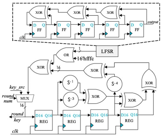
Figure 1.
Key generation circuit structure of SIMON 32/64.
3. Differential Power Attack on SIMON
Because of its lightweight structure, SIMON circuit has weak resistance to power analysis attack. Some studies have clearly demonstrated or implemented the crack of SIMON circuits through power analysis such as Refs [2,8,10,11]. The purpose of this section is to show intuitively through analysis and experiment that the SIMON circuit can be cracked by simple differential power analysis.
3.1. Selection of Power Model
The power consumption of CMOS integrated circuits consists of leakage power, short-circuit power and charge–discharge power. In the current process, leakage power and short circuit power consumption are relatively small, and the power consumption of the CMOS circuit mainly comes from the charging and discharging of the capacitive load. The charging and discharging power consumption is formed by the electrical level change of the output logic, accounting for more than 60% of the total power consumption of the chip.
According to the power consumption characteristics of CMOS circuits, Hamming Weight (HW) and Hamming Distance (HD) are the two most popular power consumption models. In addition, some more accurate models such as “switch distance” have been proposed in Ref [13] to improve the compatibility between the model and the actual power consumption. It is well known that the more precise the power model is, the more accurate the power analysis attack results will be. But those complex models make it difficult to implement power analysis attack. Therefore, HW and HD are still the most mainstream power consumption models for side channel analysis.
For power attack on SIMON circuit, Ref [13] uses HD model while Ref [2] uses a modified HD model to improve accuracy. This paper intends to reduce the impact of environmental noise by increasing the number of power traces, and to complete the power attack on SIMON circuit with a simpler and more practical HW model. HW is a power consumption representation method based on statistics, which represents the power consumption of the circuit by the number of high-level nodes in the circuit. It is usually used to simulate the power consumption for side channel analysis such as Refs [14,15]. When using the HW model, the power consumption of circuit can be expressed as:
where k denoted as the proportional coefficient between HW and power consumption, and n represents the noise in the circuit. Y represents the current state of the circuit.
3.2. Implementation of DPA on SIMON
We take the SIMON 32/64 circuit with a cyclic structure as the target to perform our DPA attack. According to the encryption process of SIMON algorithm, we chose the third round of SIMON algorithm as the attack position and lowest bit of third-round operation can be meant as Equation (5).
The expression shows that there is a non-linear relationship between L3(1), L2(16), and L2(9). According to the expression of round function of SIMON, Equation (5) can be further expanded into expressions of plaintext and round key as Equation (6):

The plaintext in Equation (6) can be divided into three parts, marked with different colors. Because the plaintext of each part has a linear relationship with the key bit, so we can select one bit of each part as a representative, and the others can be set to 0. Here, L1(7) and L1(14) are selected as the representations; then Equation (6) can be further simplified.
The constraints condition for the establishment of Equation (7) is L1(1), L1(13), L1(15), and L1(8) bits are all 0. If we only to deduce the K1(16) and K1(9), owing to the K2(1) and K1(15) involve only linear operations and have no effect the results of DPA, thus the Equation (7) can be simplified as follows:
The derived Equation (8) is the discriminant function at the location. Equation (8) shows that the Hamming Weight at L3(1) is determined by the plaintext combination {L1(14), L1(7)} and the key combination {K1(16), K1(9)}. By enumerating the plaintext combination {L1(14), L1(7)}, the K1(16) and K1(9) bits can be decoded by DPA attack. According to the deduction method, the discriminant function of the rest of the first round key is shown in Table 1.

Table 1.
The discriminant function of first round key.
For the reason that DPA is a statistical-based attack method, the power consumption curve collected during the attack must reach a certain threshold to meet the statistical law. Therefore, during the attack process, the groups whose constraint conditions and the correlation bits have no conflicts can be selected to attack at the same time. In this way, not only the number of consumption curve is increased, but also the cracking efficiency is improved. Taking the attack process to key group {K1(16), K1(14), K1(13), K1(9), K1(7), K1(5), K1(4)} as example, the correlation bits that need to be enumerated are {L1(14), L1(12), L1(11), L1 (7), L1(5), L1(3), L1(2)}, and a total of 128 kinds of plaintext are needed to enumerate the seven plaintext bits. To reduce the error caused by environmental noise, each plaintext is collected 50 times, and only 6400 power consumption curves are needed to complete the decoding of seven key bits in the first round of SIMON 32/64 algorithm.
3.3. DPA Experimental Evaluation
In this section, we present the experimental validation of the DPA attack on SIMON 32/64. In our actual attack, the key value of SIMON 32/64 is randomly set to 0x8522_a01e_83f3_a35e and {K1(16), K1(14), K1(13), K1(9), K1(7), K1(5), K1(4)} is taken as our target of retrieving.
Our DPA attack platform is shown in Figure 2 and Figure 3, including SAKURA-X board, Multi-channel digital storage oscilloscope, and PC. Our DUT (device under test) i.e., SIMON 32/64 circuit implemented on a Xilinx Kintex-7 FPGA mounted on a SAKURA-X board and the Spartan-6 FPGA on SAKURA-X board is used as a control chip to apply the excitation signal to the DUT and transfer the encryption results to the PC via the USB. At the same time, Spartan-6 FPGA also triggers a signal after each new excitation is applied to start the record of power consumption.
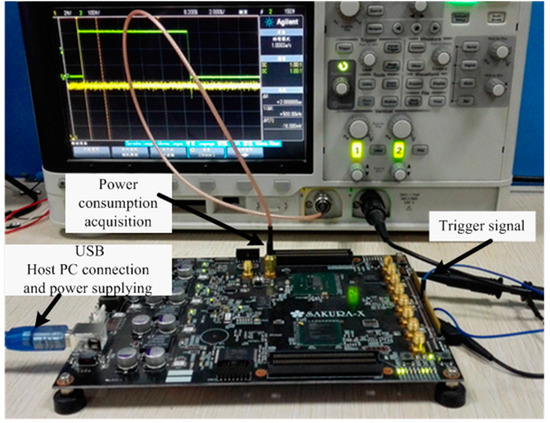
Figure 2.
Photo of differential power analysis (DPA) attack platform.
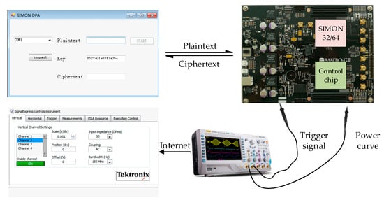
Figure 3.
The structure of DPA attack platform.
According to the previous analysis, we collected a total of 600 curves by enumerating the relevant bits of the plaintext multiple times. Through the calculation of the average of 6400 power consumption curves, the simple power analysis is completed to realize the positioning of the power attack point. Figure 4 shows a simple power analysis curve and the position of each encryption process in the power consumption curve.
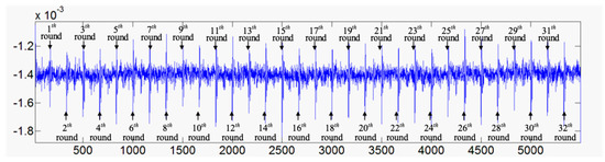
Figure 4.
Simple power analysis curve and location of the encryption process.
After locating the attack position, DPA attacks are carried out on the decrypted key groups according to the discriminant function shown in Table 1. This paper develops power analysis software based on Matlab. The execution flow of differential power analysis software is shown in Figure 5.
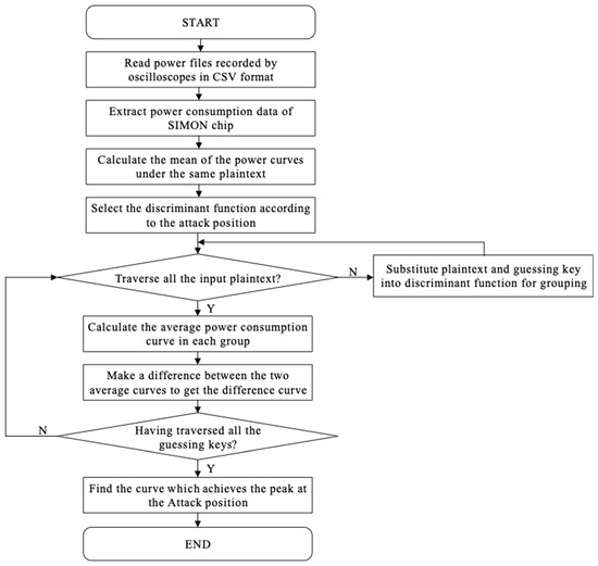
Figure 5.
Flow graph of data analysis software.
Firstly, the software reads the power consumption data file of the csv format recorded by the oscilloscope, and extracts the power voltage of the SIMON chip which represents its power consumption. Secondly, it calculates the average value of the power consumption data collected under the same plaintext to reduce the impact of environmental noise on the attack results. Subsequently, a typical differential power analysis calculation is performed according to the discriminant function in Table 1.
The results of DPA attack of {K1(16), K1(14), K1(13), K1(9), K1(7), K1(5), K1(4)} are given in Figure 6.
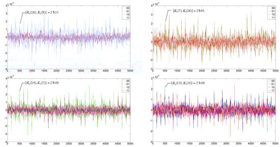
Figure 6.
The results of the DPA attack of {K1(16), K1(14), K1(13), K1(9), K1(7), K1(5), K1(4)}.
The guessed key shown in Figure 6 is {K1(16), K1(14), K1(13), K1(9), K1(7), K1(5), K1(4)}=7’b1001000, which is consistent with the preset first round key 16’h8522, indicating that the DPA attack successfully cracked the 7 bits of key.
4. DPA-Resistant SIMON Based on Power Randomization
4.1. Design of DPA-Resistant SIMON
The lightweight cryptographic algorithm was originally designed to provide security for resource-constrained scenarios such as the IoT system. Therefore, for SIMON, the resource consumption of encryption circuits and circuit security are almost equally important. In this Section, according to the characteristics of round function on SIMON, a power randomization method for round function is proposed as a compact countermeasure against DPA. Figure 7 shows the circuit structure of the round function circuit of SIMON algorithm.
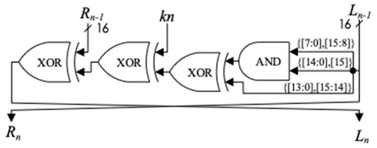
Figure 7.
The structure of round function circuit.
According to the principle of DPA attack, it can be known that as long as the power consumption of the SIMON round function circuit is randomized, the DPA cannot get the key information of the circuit through the differential operation. Therefore, we can randomly insert a redundant round operation before or after each encryption round to randomize the power consumption. However, with the insertion of redundant operations, the calculation period of the round function will be doubled, and the data throughput of the whole circuit will become half of the original. In order to solve this problem, we use the double rate technique for the compact structure of SIMON algorithm round function. It can be seen from Figure 7 that the structure of the round function is quite compact, consisting only of one set of AND gates and three sets of XOR gates that means the critical path of the SIMON round circuit is quite short, and it will not become a critical path for a complex system, so the double rate technology is feasible.
In this paper, the SIMON 32/64 circuit is implemented in a cyclic structure, and the structure of a circuit optimized by the anti-power attack is shown in Figure 8.
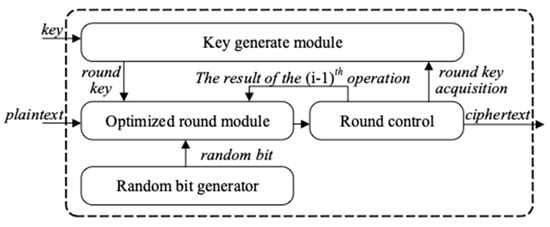
Figure 8.
Overall circuit architecture of DPA-resistant SIMON.
The double rate technology was first used in the Ref [16] to resist power attacks. That work proposes to use double rate technology to pre-charge each register in round function of AES so that the Hamming distance in the encryption process will be changed randomly. However, that method needs to input a set of random data before normal encryption to randomize power consumption. The generation and preservation of multi-bit random data require a certain circuit area, which is not advisable for area-sensitive lightweight cipher circuits such as SIMON.
To complete the power randomization with low resource consumption, random data in this paper is generated by injecting a fault into the plaintext and utilizing the fault diffusion effect of SIMON algorithm. We inject a 1-bit fault into the Jth bit of plaintext, according to the operation of the round function of SIMON, the influence of this 1-bit fault on the subsequent rounds is as shown in Table 2.
Table 2.
The influence of the 1-bit fault injected in the Jth bit of plaintext.
In Table 2, we only consider the effect of the fault bit in the left half part on the subsequent encryption round. The overlined bits such as in the table indicate there is a possibility that the location is affected by the fault bit. The reason for this phenomenon is that the round function of SIMON algorithm contains an AND operation. Taking the (J+8)th bit of the left part in the first round as an example, according to the SIMON round function calculation, this bit can be expressed as Equation (9).
Whether the (J + 8)th bit in the first round will be affected by the fault injected in PL(J) depends on the value of PL(J + 7), and L1(J + 8) is affected by the fault only if PL(J + 7) is 1.
As shown in Table 2, a 1-bit fault injected in the plaintext has an increasing influence on the output of each round as the number of encryption rounds increases, and the specific diffusion effect is affected by the different plaintext. Thus, it can be assumed that injecting a 1-bit fault into the plaintext will have an extremely complicated effect on the encryption of SIMON algorithm. According to the fault diffusion characteristic of SIMON algorithm, the power consumption of SIMON circuit can be randomized by introducing a 1-bit random fault into the input plaintext, which can be used to replace the random data in Ref [16]. The schematic diagram of fault injection is shown in Figure 9.
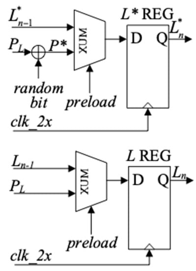
Figure 9.
The schematic diagram of fault injection.
The upper part of Figure 9 schematically describes the register and fault inject circuit for the faulty plaintext, and the lower part of Figure 9 is the register to store normal left part data of round function. The specific injection circuit is shown in Figure 10. When the input plaintext preloads the L* register, the 1-bit fault is introduced in the last two bits of the plaintext in the left half part by a random bit.
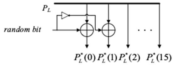
Figure 10.
The structure of fault introducing circuit.
Based on this concept, a compact power attack countermeasure is proposed in this paper. Its structure is shown in Figure 11.
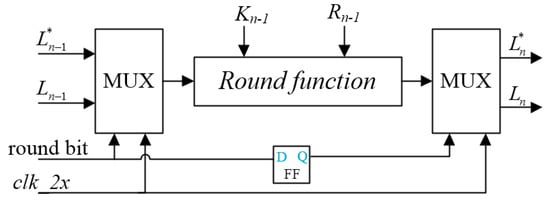
Figure 11.
Block diagram of SIMON round circuit by double rate technology.
By using double rate system clock and a random selection bit, the encryption operation and the power hiding operation are carried out randomly in the first half cycle and the second half cycle of the round function circuit, which makes the attacker unable to carry out the differential analysis correctly.
4.2. Random Bit Generation Circuit
The countermeasure proposed in this paper needs to use a random bit. A two-stage ring oscillator (RO) is designed to form a random bit generator, the structure is shown in Figure 12.
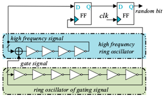
Figure 12.
Circuit diagram of 1-bit random generator.
In this circuit, a long RO circuit composed of an odd number of NOT gates generates a low-frequency gating signal, a short RO circuit composed of an even number of NOT gates and an XOR gate generates a high-frequency signal. The short RO will oscillate as long as the gate signal generated by long RO chain is equal to 1. Otherwise, the short RO will stop oscillate and keep current state (Figure 13).
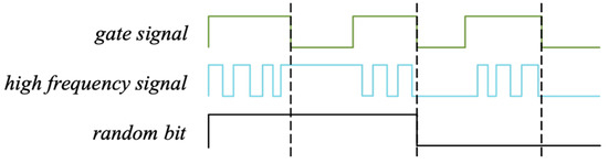
Figure 13.
1-bit random number generator working principle diagram.
The transmission delay of the gate circuit fluctuates with changes in temperature and voltage, so the period of the oscillating chain also exhibits a small random fluctuation. Since the period of the gating signal period and the high-frequency oscillating signal are all randomized when the gating signal is 0, the state of the short RO will be a random value.
The smaller the inverters number of short RO and the greater the difference in the inverters number between the two RO, the randomness of the generated bit will be better. We made the long RO contain 27 inverters, and the short RO consisted of 4 inverters as an example. This random bit generator requires 33 LUTs and 2 registers. We implemented this architecture in a Xilinx Kintex-7 series FPGA with speed grade -1, the long RO has an average oscillation frequency of 77 MHz, and the short RO has an average oscillation frequency of 478 MHz.
4.3. Implementation of Optimized SIMON Circuit
The designed circuit is verified in xc7k160tfbg676-1 FPGA and analysis of resource utilization in comparison to the original design are shown in Table 3.
Table 3.
Resource utilization and performance report of original and optimized SIMON 32/64.
The optimized circuit increases 47 LUTs and 46 registers as compared to the original circuit. The maximum frequency of the FPGA is reduced by 11.2%, but still can achieve 277 MHz, meeting the needs of most IoT and embedded systems.
Table 4 shows the comparisons with other DPA-resistant SIMON circuits of threshold implementation [11] and bool mask [2]. It can be seen that our countermeasure consume lower resource overhead and keep high performance.
Table 4.
Comparisons with other DPA-resistant SIMON circuits.
5. Leakage Quantification
As we all know, the countermeasures based on dual-rate technology have good resistance to power analysis which based on HD model. This paper also randomizes the execution sequence of redundant operations and normal encryption operations in dual-rate technology. The randomization of the execution time of the round operation makes the Hamming weight of any half cycle present a certain degree of randomness, which can also resist the power analysis based on the Hamming weight model.
In order to analyze the countermeasure more objectively, we use t-test to evaluate the practical security of the proposed designs with leakage quantification. T-test is a statistical method used to judge whether two sample sets come from the same group. It is used to evaluate the power leakage of circuits in Refs [17,18,19]. Compared with power analysis attack, t-test can quantitatively analyze the DPA-resistant ability of circuits, which is more convincing. The t-test is then computed on two sets, one with a fixed plaintext while the other with randomly varying plaintexts, and t-test can be expressed as follows:
where and are the sample means of two data sets, N denotes the trace number of each set, and and refer to the standard deviation. As in Ref [11], we use |t| > 4.5 as a threshold to determine whether there is any information disclosure.
We executed 10,000 times of fixed plaintext and random plaintext encryption operations respectively and collect a total of 20,000 power traces. Substituting the collected power consumption values into Equation (10) to complete the t-test calculation. The t-test result of the optimized circuit is shown in Figure 14.
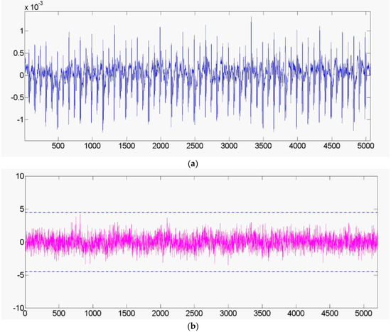
Figure 14.
(a) The power trace of the optimized SIMON 32/64. (b) The t-test result of the optimized circuit.
Figure 14a reports the power trace collected from the optimized SIMON 32/64 circuit and Figure 14b reports the t-test result. The original SIMON circuit that has been proven in Section 3 can be cracked by DPA attack, while the protected circuit does pass the t-test which again supports our claim of secrecy.
This section proves the resistance of the proposed method to DPA from both quantitative and qualitative analysis, but does not elaborate whether it can resist high-order differential analysis (HO-DPA). Although HO-DPA attacks are more complex to implement, they can crack many circuits that are resistant to common DPA attacks. It is necessary for the chip designer to conduct research on the anti-HO-DPA capabilities of cryptographic chips, which will be our further work.
6. Conclusions
This paper proposes a compact countermeasure against DPA on SIMON. Firstly, we present that SIMON algorithm can be threatened by DPA attack, and implement an example of 7-bit key cracking on SAKURA-X board. Subsequently, based on the fault injection technique and the double rate technique, we propose a low-cost DPA-resistant design scheme. By injecting a 1-bit fault into plaintext to form a random data, and uses the double rate technique to insert the encrypting process of random plaintext before or after normal encryption operation randomly to realize the randomization of power consumption. According to the proposed optimal scheme, the circuit structure, random bit generator, and other circuits are implemented. As well as, the evaluation of resources and performance is carried out in Xilinx FPGA. The evaluation results show that the proposed scheme completes the DPA-resistant optimization of SIMON circuit at the cost of 47 LUTs and 46 registers.
Compared with existing works, proposed work is the first one to combine fault injection and double rate technology for DPA attack defense, which makes the SIMON circuit achieve DPA-resistant with 47.7% LUTs and 39.6% registers overhead. Compared with threshold implementation and bool mask, our work has greater advantages in resource consumption, which allows the design philosophy of lightweight cipher algorithm.
Author Contributions
Conceive and structure of the concept of this paper, Y.Z.; Resources, F.Z. and N.W.; Supervision, N.W.; Writing-original draft, Y.Z.; Writing-review and editing, M.R.Y. and J.Z.
Funding
This work was supported by National Natural Science Foundation of China (No. 61774086, 61376025), Natural Science Foundation of Jiangsu Province (No. BK20160806), the Fundamental Research Funds for Central Universities (No. NS2017023, NO. NS2016041).
Acknowledgments
The authors would like to thank Xiaoqiang Zhang for his beneficial suggestions and comments.
Conflicts of Interest
The authors declare no conflict of interest.
References
- Beaulieu, R.; Shors, D.; Smith, J.; Treatman-Clark, S.; Weeks, B.; Wingers, L. The SIMON and SPECK lightweight block ciphers. In Proceedings of the 52nd ACM/EDAC/IEEE Design Automation Conference (DAC), San Francisco, CA, USA, 8–12 June 2015; pp. 1–6. [Google Scholar] [CrossRef]
- Bhasin, S.; Graba, T.; Danger, J.L.; Najm, Z. A look into SIMON from a side-channel perspective. In Proceedings of the 2014 IEEE International Symposium on Hardware-Oriented Security and Trust (HOST), Arlington, VA, USA, 6–7 May 2014; pp. 56–59. [Google Scholar] [CrossRef]
- Fu, K.; Sun, L.; Wang, M. New integral attacks on SIMON. IET Inf. Secur. 2017, 11, 277–286. [Google Scholar] [CrossRef]
- McCann, D.; Eder, K.; Oswald, E. Characterising and Comparing the Energy Consumption of Side Channel Attack Countermeasures and Lightweight Cryptography on Embedded Devices. In Proceedings of the 2015 International Workshop on Secure Internet of Things (SIoT), Vienna, Austria, 21–25 September 2015; pp. 65–71. [Google Scholar]
- Zhang, F.; Guo, S.; Zhao, X.; Wang, T.; Yang, J.; Standaert, F.X.; Gu, D. A Framework for the Analysis and Evaluation of Algebraic Fault Attacks on Lightweight Block Ciphers. IEEE Trans. Inf. Forensics Secur. 2016, 11, 1039–1054. [Google Scholar] [CrossRef]
- Matsuda, S.; Moriai, S.; Zhang, W.; Bao, Z.; Lin, D.; Rijmen, V.; Yang, B.; Verbauwhede, I. RECTANGLE: a bit-slice lightweight block cipher suitable for multiple platforms. Sci. China Inf. Sci. 2015, 58, 408–425. [Google Scholar]
- Al-Qutayri, M.; Marzouqi, H.; Salah, K. Review of gate-level differential power analysis and fault analysis countermeasures. IET Inf. Secur. 2014, 8, 51–66. [Google Scholar]
- Yoshikawa, M.; Nozaki, Y. Power Analysis Attack and Its Countermeasure for a Lightweight Block Cipher Simon. In Information Technology: New Generations; Springer: Cham, Switzerland, 2016; pp. 151–160. [Google Scholar]
- Shahverdi, A.; Taha, M.; Eisenbarth, T. Lightweight Side Channel Resistance: Threshold Implementations of Simon. IEEE Trans. Comput. 2017, 66, 661–671. [Google Scholar] [CrossRef]
- Chen, C.; İnci, M.S.; Taha, M.; Eisenbarth, T. SpecTre: A tiny side-channel resistant speck core for FPGAs. In International Conference on Smart Card Research and Advanced Applications; Springer: Cham, Switzerland, 2017; pp. 73–88. [Google Scholar]
- Shahverdi, A.; Taha, M.; Eisenbarth, T. Silent Simon: A threshold implementation under 100 slices. In Proceedings of the 2015 IEEE International Symposium on Hardware Oriented Security and Trust (HOST), Washington, DC, USA, 5–7 May 2015. [Google Scholar]
- Ahir, P.; Mozaffari-Kermani, M.; Azarderakhsh, R. Lightweight Architectures for Reliable and Fault Detection Simon and Speck Cryptographic Algorithms on FPGA. ACM Trans. Embed. Comput. Syst. 2017, 16, 1–17. [Google Scholar] [CrossRef]
- Peeters, E.; Standaert, F.X.; Quisquater, J.J. Power and electromagnetic analysis: Improved model, consequences and comparisons. Integration 2007, 40, 52–60. [Google Scholar] [CrossRef]
- Sasaki, A.; Abe, K. Algorithm-level evaluation of DPA resistance to cryptosystems. Electr. Eng. Jpn. 2008, 165, 37–45. [Google Scholar] [CrossRef]
- Prouff, E.; Rivain, M.; Bévan, R. Statistical analysis of second order differential power analysis. IEEE Trans. Comput. 2009, 58, 799–811. [Google Scholar] [CrossRef]
- Bellizia, D.; Bongiovanni, S.; Monsurrò, P.; Scotti, G.; Trifiletti, A.; Trotta, F.B. Secure Double Rate Registers as an RTL Countermeasure Against Power Analysis Attacks. IEEE Trans. Very Large Scale Integr. Syst. 2018, 26, 1368–1376. [Google Scholar] [CrossRef]
- Goodwill, G.; Jun, B.; Jaffe, J.; Rohatgi, P. A testing methodology for side-channel resistance validation. NIST Non-Invasive Attack Test. Workshop 2011, 7, 115–136. [Google Scholar]
- Leiserson, A.J.; Marson, M.E.; Wachs, M.A. Gate-Level Masking under a Path-Based Leakage Metric. In International Workshop on Cryptographic Hardware and Embedded Systems; Springer: Berlin/Heidelberg, Germany, 2014; pp. 580–597. [Google Scholar]
- Bilgin, B.; Gierlichs, B.; Nikova, S.; Nikov, V.; Rijmen, V. Higher-Order Threshold Implementations. In International Conference on the Theory and Application of Cryptology and Information Security; Springer: Berlin/Heidelberg, Germany, 2014; pp. 326–343. [Google Scholar]


© 2019 by the authors. Licensee MDPI, Basel, Switzerland. This article is an open access article distributed under the terms and conditions of the Creative Commons Attribution (CC BY) license (http://creativecommons.org/licenses/by/4.0/).