A New Type of AODF Based on an Imitation of the Weft Insertion of a Rapier Loom


School of Automation, Beijing University of Posts and Telecommunications, No 10, Xitucheng Road, Haidian District, Beijing 100876, China
*
Author to whom correspondence should be addressed.
Electronics 2019, 8(2), 157; https://doi.org/10.3390/electronics8020157
Submission received: 1 November 2018
/
Revised: 9 January 2019
/
Accepted: 17 January 2019
/
Published: 1 February 2019
(This article belongs to the Special Issue Optical Communications and Networks)
Abstract
:The main distribution frame (MDF) is an important component between the user and the operator that supplies a telecommunication service and is the only layer in the seven-layer communication architecture that is not fully automated. In this paper, a cross-connect method for simulating the rapier picking of a rapier loom (shuttleless loom) is proposed to imitate the shedding and the picking action to achieve quick switching. Using the designed “shedding device” and “picking device”, a model prototype of the automatic optical distribution frame (AODF) was constructed and tested for verification.
1. Introduction
The main distribution frame (MDF) is an important component between external equipment and the user of a communication network supplied by the operator. The MDF contains a large number of physical connections and is the only layer in a seven-layer communication architecture that is not fully automated [1,2,3,4]. Traditionally, cross-connections on patch panels are manually installed, but manual operation is complicated and time-consuming and the possibility of errors exists. Because a large number of optical fibers are used in communication networks, operators are required to offer high-level reliability services to customers, quickly resolve line failures, and reduce the costs of operation and maintenance. Service providers have strict requirements for the automatic optical distribution frame (AODF) [5,6,7,8,9,10].
In communications, the AODF is complicated, and although it was proposed quite early on, few studies have been conducted on its automation [11,12,13,14,15,16]. Although commercially available AODF products began to appear on the market in the late 2000s, Fiberzone-Networks [12], Telescent [13], Teliswitch Solutions [14], and Huawei [15] provide AODF products, but in small quantities because the current robotic approaches have limitations. Due to the difficulties associated with robotic systems, many organizations use nonrobotic structures such as microelectromechanical systems (MEMS), beam steering, the asymmetrical approach, and locking optical coupling technology [17,18].
Fibers are present in the MDF and in looms. A loom is a device that interlaces two sets of yarns (i.e., warp and weft) to produce fabric [19,20,21,22,23]. Based on the weft insertion device, weaving machines are divided into shuttle looms and shuttleless looms. The three most popular weaving machines are the jet, rapier, and projectile types. The rapier loom uses a flexible or rigid rapier as a weft insertion device to achieve insertion of the weft, and this loom is known for its reliability and performance [24,25,26,27].
Previously [28], we proposed a “higher always on top” nonwinding cross-connect method based on the spatial relationship of noncoplanar lines and proposed the analogy of a rapid switching method that imitates the picking of a shuttle. The design of the actuator is complicated due to the small gap between the fibers in the MDF. Imitation of the initial shedding of the loom and subsequent picking is better than the simple imitation of the picking of a shuttle, and the requirements for the actuator are not strict. The relationship between warp and weft threads in a textile from a loom is similar to the noncoplanar lines’ spatial relationship of a one-dimensional array of input lines and a one-dimensional array of output lines using a line-match line. In this paper, we propose a cross-connect method that imitates the rapier loom using rapier picking. Imitation of the shedding action and the picking action are used to realize quick switching. The shedding action is achieved by the shedding mechanism, which is the same as forming a shed in a loom. Enlarging the distance between the fibers is beneficial for the robot switching. Picking acts to insert the weft into the shed so that the warp and weft are interlaced. We regarded the target patch cord to be connected as a weft and the switching operation as being similar to the weft insertion, and the robot removes the fiber from the current port and moves it along a specific path (like the shed) to the target port. We designed a “shedding device” and a “picking device”, used Petri nets to characterize the workflow of the entire system, and built the virtual prototype and experimental model for verification [29,30,31,32,33,34,35].
2. Cross-Connect Method
The textile industry is a traditional stalwart throughout world industry history, and this technology dates back thousands of years. Silk fabrics and ramie fabrics unearthed in Zhejiang Province, China, have a history longer than 4700 years. The loom is a device that interlaces two sets of yarns to produce a fabric, and the first loom was a shuttle loom. The weft insertion device is the most important component of the weaving machine, and its type is usually the basis for classification of the loom. According to the weft insertion method, the loom can be divided into two categories. The traditional shuttle is used as a weft inserter, and this type of loom is known as a shuttle loom. The other type includes a series of looms that were invented at the beginning of the 20th century. The weaving machine that introduces the weft yarn from a fixed bobbin into the shed using a high-speed jet, or a light weft inserter, is known as the shuttleless loom because it does not use the traditional shuttle, replacing it with air, projectiles, rapiers, and water as the weft insertion media. The rapier loom is the most widely used shuttleless loom and is high-speed, highly automated, and produces high-quality products. The weft insertion method of the shuttleless loom varies widely, can be adapted to the weft insertion of various types of yarns, and offers obvious advantages in multicolor weft weaving.
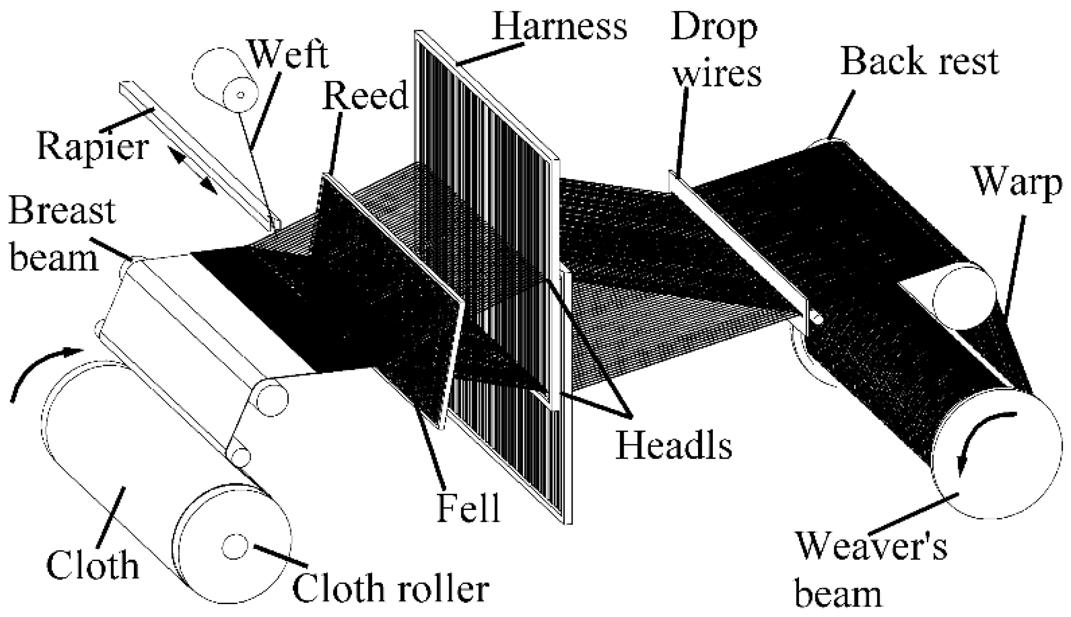
The rapier loom uses a flexible or rigid rapier as a weft insertion device to insert the weft and is known for its reliability and performance. The rapier loom is the most commonly used configuration in shuttleless looms. The rapier head picks up the filling yarn and takes it through the shed. After reaching the destination, the empty rapier head returns to pick up the next weft to complete a cycle. Two types of rapier looms exist: (1) Single rapier looms use a single rigid rapier loom that enters the shed from one side, picks up the tip of the filling yarn on the other side, and passes it through the loom as it shrinks, as shown in Figure 1. (2) Double rapier looms are operated by a giver head taking the filling yarn from the yarn storage from one side of the weaving machine, carrying it to the centre of the machine, and transferring it to the taker. The taker retracts and brings the filling yarn to the other side. Similar to a single rapier loom, only half of the rapier movements are used in weft insertion. The double rapier configuration can be rigid or flexible. In a flexible rapier loom, the rapier loom has a ribbon structure that can be wrapped around the drum, thus conserving space and allowing a narrower machine width. Double flexible rapier looms are more common than rigid rapier looms.
The warp yarn is sent from the weaver’s beam by the feeding mechanism, passes through the back rest and the drop wires to the harness, penetrates into the heddle eye of the harness according to a certain law, and passes through the reed that holds the warps at uniform spacing. This element is designed to beat up the weft thread. The harness is controlled by the shedding mechanism to separate the warp threads into two warp layers to form a shed. The rapier enters the shed from one side, picks up the tip of the weft to the other side of the weaving machine, and retracts to complete the weft insertion. The shed is closed, and during the closing process, the reed pushes the weft yarn to the fell for beat-up to complete a weaving cycle. In the next weaving cycle, the harness exchange position interlaces the upper and lower warp yarns to form a new shed.
It can be observed from the process of fabric formation that the lifting rule of the harness determines the interlacing law of the fabric. In the fabric, all the raised warp yarns are located above the weft yarn, and all the warp yarns that are not lifted lie under the weft yarn. To interlace the warp and weft threads, the loom must conduct the following important operations: (1) Shedding involves the separation of the warps into two sheets, one of which is lifted and the other lowered to form the shed for the weft insertion. (2) Picking involves the insertion of the weft yarn through the shed. (3) Beat-up involves the pushing of the inserted weft into the fabric fell. (4) Wrap let-off includes the delivery of the warp to the formation zone at the required rate and at a suitable constant tension by unwinding it from the weaver’s beam. (5) Cloth take-up involves the movement of fabric from the formation zone at a constant rate that ensures the required pick spacing and winding of the fabric onto a cloth roller.
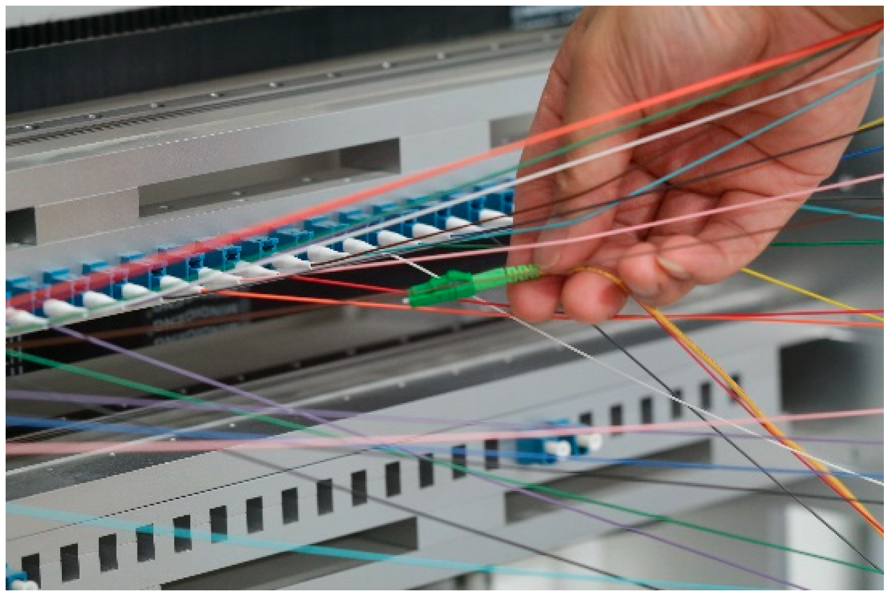
In our previous study [28], we found that the separated warp threads and the weft thread that is inserted into the shed are noncoplanar lines, and the process of switching is similar to the picking process. When the cross-connect is manually performed, the connector is pulled by the fingers and held by the fingers to pass through the gap between the fibers before it is inserted into the target port. When the hand passes, the shedding action is automatically completed, and the distance between the fibers is enlarged so that human fingers can hold the connector through (Figure 2). Based on the automatic opening of the hand during the cross-connect process, or use of another hand to expand the gap between the fibers, we propose using the cross-connect method of imitating the rapier weft insertion of the rapier loom. The connected fiber patch cords are treated as warps, and the target fiber to be connected is viewed as a weft. The shedding operation is performed using a “shedding mechanism” to expand the distance between the fibers, and the rapier is applied for weft insertion, i.e., the robot is used to pull out the target fiber from the current port and insert it into the target port. The robot exits to complete the “picking” operation, and the shedding mechanism closes the shed to complete the switching process.
3. Design of the Shedding Mechanism
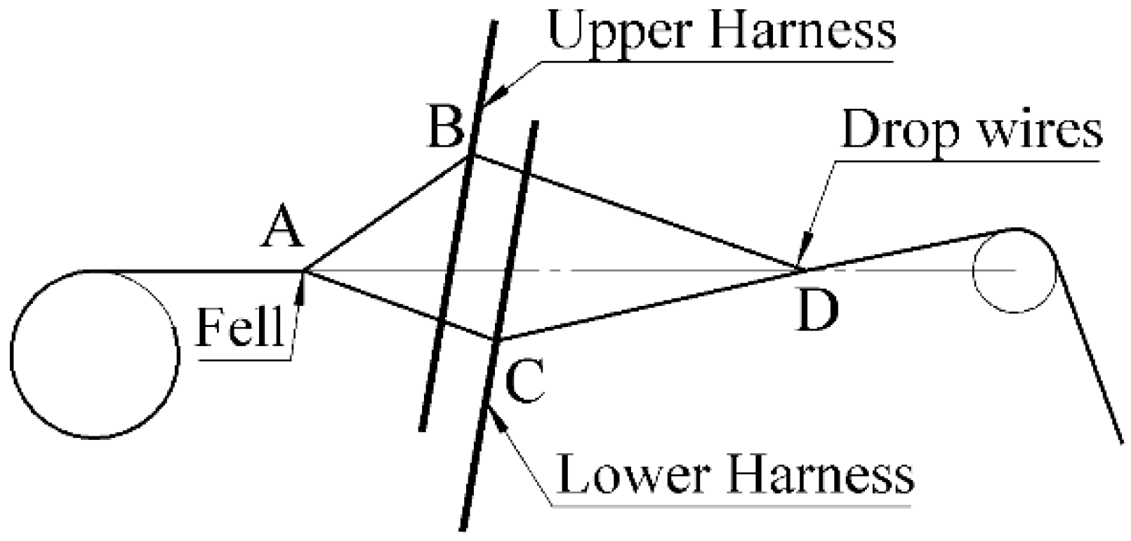
The shedding action is achieved by a shedding mechanism that causes the warp yarns to layer up and down to form a shed sufficient for the rapier to pass through. As shown in Figure 1, two harnesses were used to achieve the shedding action. The warp yarn is divided into upper and lower layers with the lifting movement of the harness, and viewed from the side, a quadrilateral channel ABDC is formed in the middle of the two layers of warp yarns (Figure 3), which is the shed. The four vertices of the quadrilateral ABCD are the fell, the upper harness, the lower harness, and the drop wires, respectively. The front half of the shed ABC is the working component of the shed, from which the rapier passes and fills in the weft yarn to complete the warp and weft interlacing.
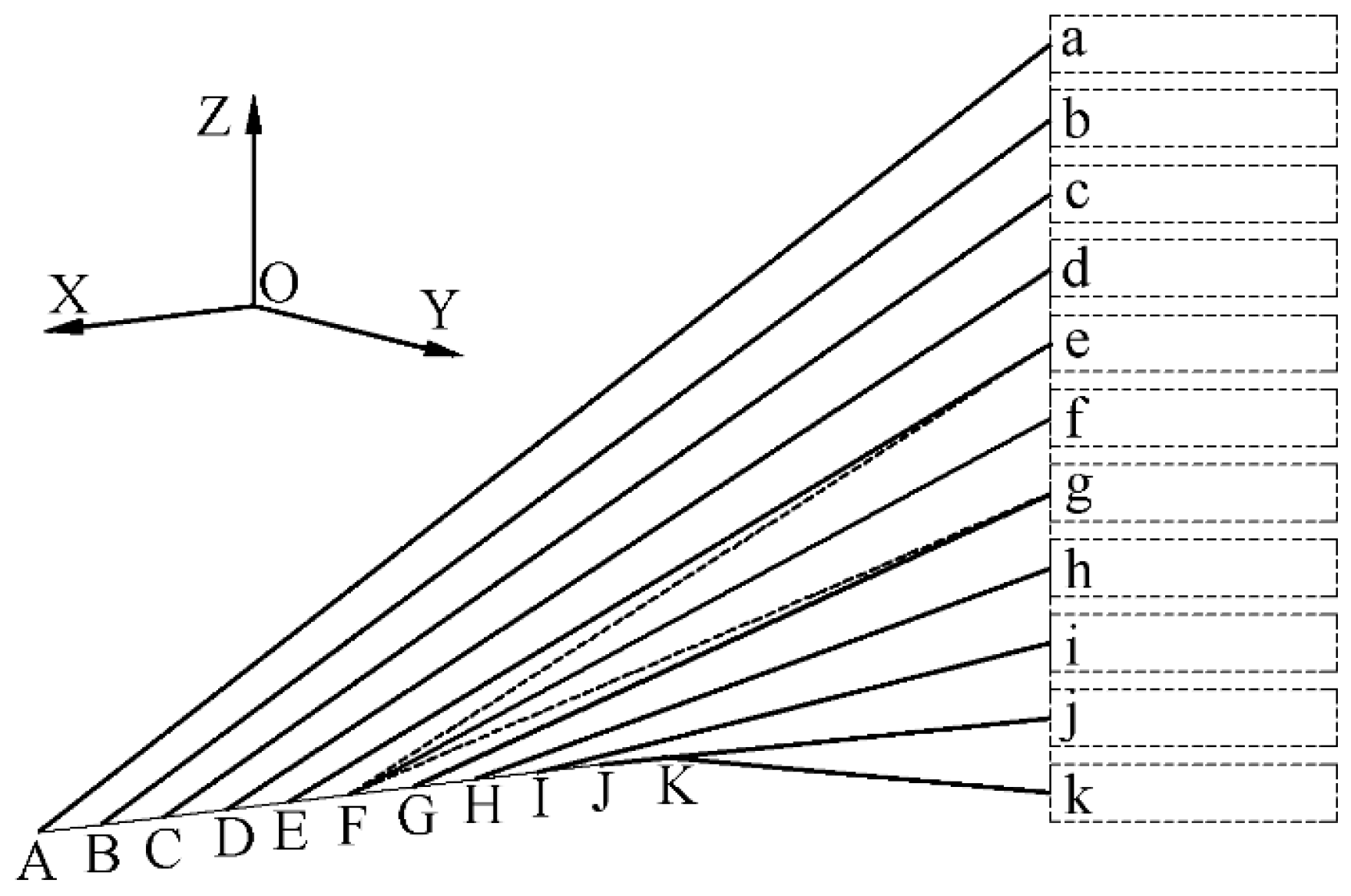
The harness is composed of the outer frames and many heddles. With a hole in the middle in a side-by-side manner, each warp thread passes through the heddle eye of the corresponding heddle. Each fiber on the MDF corresponds to a fiber storage container that supplies elastic tension, and each fiber storage container can be treated as a heddle. The fiber storage containers arranged together can be viewed as a harness. Figure 4 shows a model of a sequential one-dimensional (1-D) to 1-D form, and the dotted box on the right side of the figure indicates the fiber storage container, which can be treated as a heddle eye that passes through the warp.
We previously [28] described the fibers in the 1-D to 1-D form, which are constructed in a noncoplanar relationship and are perpendicular to each other, and each fiber moves in its own layer. As shown in Figure 3, if the port is established on the X-axis of the illustrated coordinate system, it is easy to determine the plane of any layer where the fiber is located, such as the plane where fiber f is located:
where is the Y coordinate of point f and is the Z coordinate of point f.
The number of harnesses on the loom and the different lifting sequences of the harness form the organization of different fabrics, such as a plain weave or a twill weave. The number of harnesses is determined by the texture, and when the texture is determined, the number of harnesses is determined. The fiber patch cords that operate on the MDF are random and not known in advance, but only one of the optical fiber patch cords is operated during the switching operation. To facilitate the operation, the area where the shedding operation is enlarged is a triangular area located on both sides of the target optical fiber patch cord. At the same time, the texture formed by the cross-connect is a “nonwinding” texture, and the two harnesses meet the requirements of the cross-connect. As shown in Figure 4, if the target fiber for the switching operation is fiber f, the shed is a triangular prism with eFg as a cross section as shown in Figure 4, the weaving fell is the X-axis, and the corresponding harnesses are the upper harness formed by the upper fiber storage containers a–e, and the lower harness is formed by the lower fiber storage containers g–k. If the target fiber is fiber c, the harnesses are a–b and d–k, respectively.
In the loom, the harness is located on the rear side of the effective shed, on the 1-D to 1-D form MDF. The harness is also located on the rear side of the effective shed, and the formed shed contains only the effective portion. The width of the harness in the loom is the width of the weaving fell, which horizontally covers the width of all of the warp threads. On the 1-D to 1-D form MDF, the fiber storage containers and the adapter ports side are perpendicular to each other, i.e., the harness and the fell are vertical, and the position is set according to the needs of the fiber patch cords. Preferably, there are two forms, and the fiber sequence of Figure 4 is projected onto the plane XOY, as shown in Figure 5. In the X-axis direction, the position of the fiber storage containers can be set in the middle of the adapter port side (Figure 5a). It can also be set on one side of the adapter port side (Figure 5b). When the rapier is used in weft insertion, the weft thread must be moved from one side of the shed to the other. When the fiber is cross-connected, the rapier robot must also be able to move the fiber from one end of the adapter ports side to the other, i.e., move from port A to port K. R1 and R2 in Figure 5 represent the rapier robot in two cases, as can be observed from the figure. It is easy to know:
where R1 is the length of the rapier robot when the fiber storage containers are in the middle, R2 is the length when the fiber storage containers are on one side, and AK is the length from port A to port K.
For the switching operation, the rapier robot moves at the shed and the adapter ports are located on the fell, i.e., the X-axis, which is also the position the actuator of the robot must reach. As shown in Figure 6, the dotted line box shows a rapier robot for switching performance, and in the Z-axis direction, the adapter port is displayed at the middle of the fiber storage containers.
The shedding mechanism of the AODF was designed according to the position of the adapter port side and the fiber storage containers, as shown in Figure 7. The shedding mechanism is divided into upper and lower components, and the two “harnesses” described above are operated separately. The shedding mechanism operates the harness composed of the fiber storage containers through the bottom plate of the sliding table and the locking device. When the AODF receives an instruction to perform switching, the target fiber is determined and the upper and lower shedding mechanisms simultaneously move toward the middle. The upper sliding table moves downward to the bottom plate to contact the uppermost fiber storage container, and the locking device moves downward to the upper side of the target fiber storage container and locks in the upper position of the target optical fiber so that all the upper portions of the target optical fiber become a “harness”. The lower sliding table moves upward to the bottom plate to contact the lowermost fiber storage container, and the locking device moves upward to the lower side of the target optical fiber storage container and locks in the lower position of the target optical fiber such that all of the optical fibers in the lower portion of the target optical fiber become a “harness”.
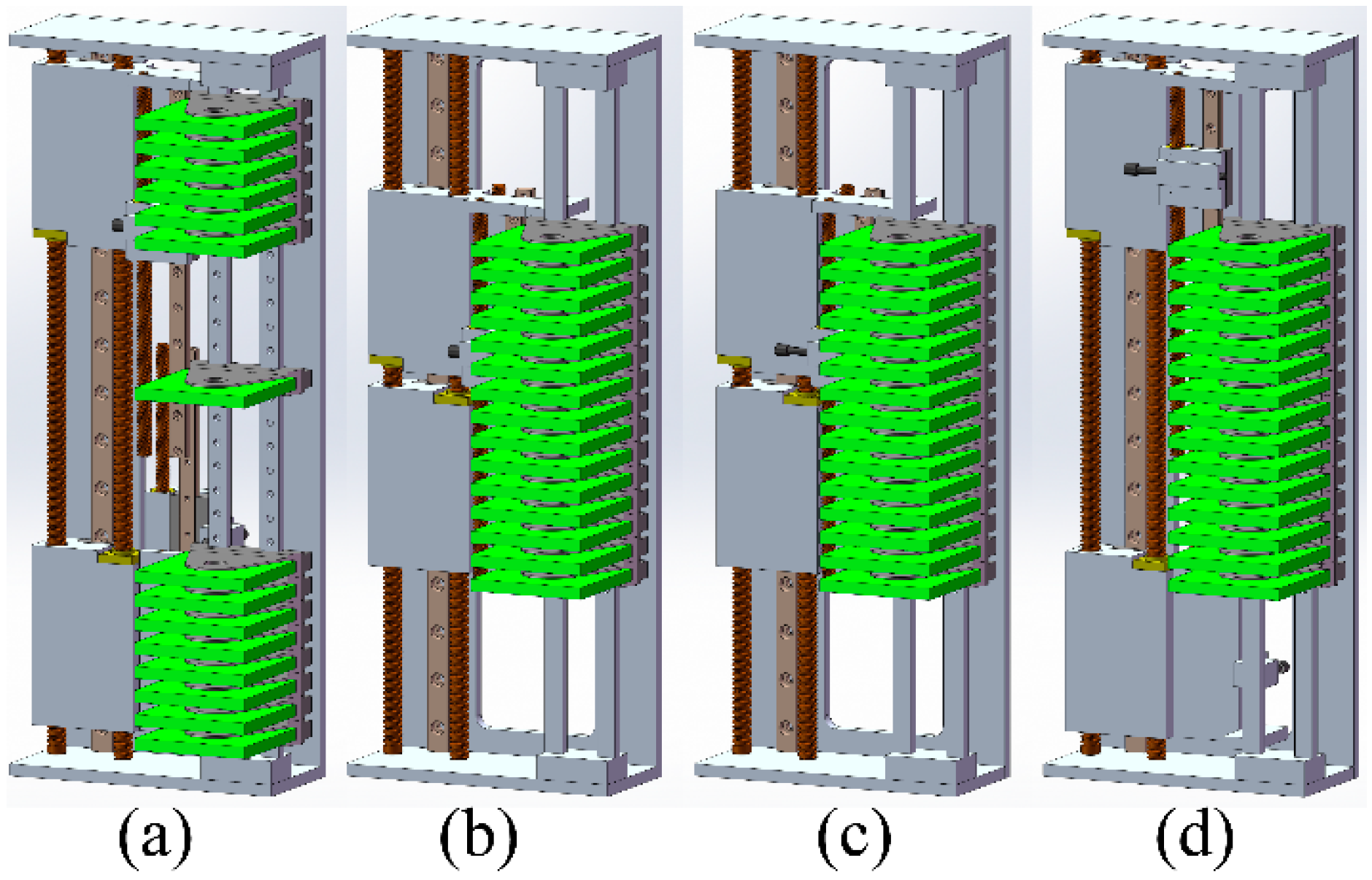
Figure 8 shows the rectification process of the shedding mechanism for the shedding action. The initial-state fiber storage containers are arranged in the middle position in order, and the upper and lower sliding tables are located at both ends (Figure 8a). After the target fiber is determined, the upper and lower sliding tables each move to the middle until they both contact the fiber storage containers (Figure 8b). The upper and lower locking devices each move to the two sides of the target optical fiber storage container for locking (Figure 8c). After locking, the upper and lower sliding tables move to both sides to form the shed (Figure 8d).
When the shedding is completed, the rapier robot performs the switching operation, the robot is withdrawn after the target fiber is inserted into the target port, and the upper and lower sliding tables simultaneously move to the middle from the shedding state (Figure 9a) to reset the fiber storage containers (Figure 9b). The locking device unlocks (Figure 9c) and is moves to the initial state on both sides (Figure 9d) to complete the entire switching process.
4. Design of the Rapier Robot
Picking is the insertion of the weft yarn through the shed into the shed formed by the warp shedding. The picking mechanism on the loom carries the weft thread from one side of the shed to the other to complete weft insertion. We considered the target fiber to be a weft and the switching operation to be similar to the picking process. The fiber is removed from the current port and subsequently moved to the target port along a specific path (similar to the shed). The rapier loom uses a flexible or rigid rapier as a weft insertion device to achieve insertion of the weft. The rapier head holds the filling yarn and takes it through the shed. The earliest to appear is a single rapier loom, which is mounted on one side of the loom with a long rapier that is wider than the width of the cloth and its transmission mechanism, which carries the weft thread through the shed to the other side. Alternatively, the empty rapier sticks into the opposite side of the shed to clamp the weft during the exit process, and the weft is pulled into the shed to complete the weft insertion. Because the single rapier is wider than the cloth width, the loom is larger and a double rapier loom is developed. The double flexible rapier loom reduces the size of the loom.
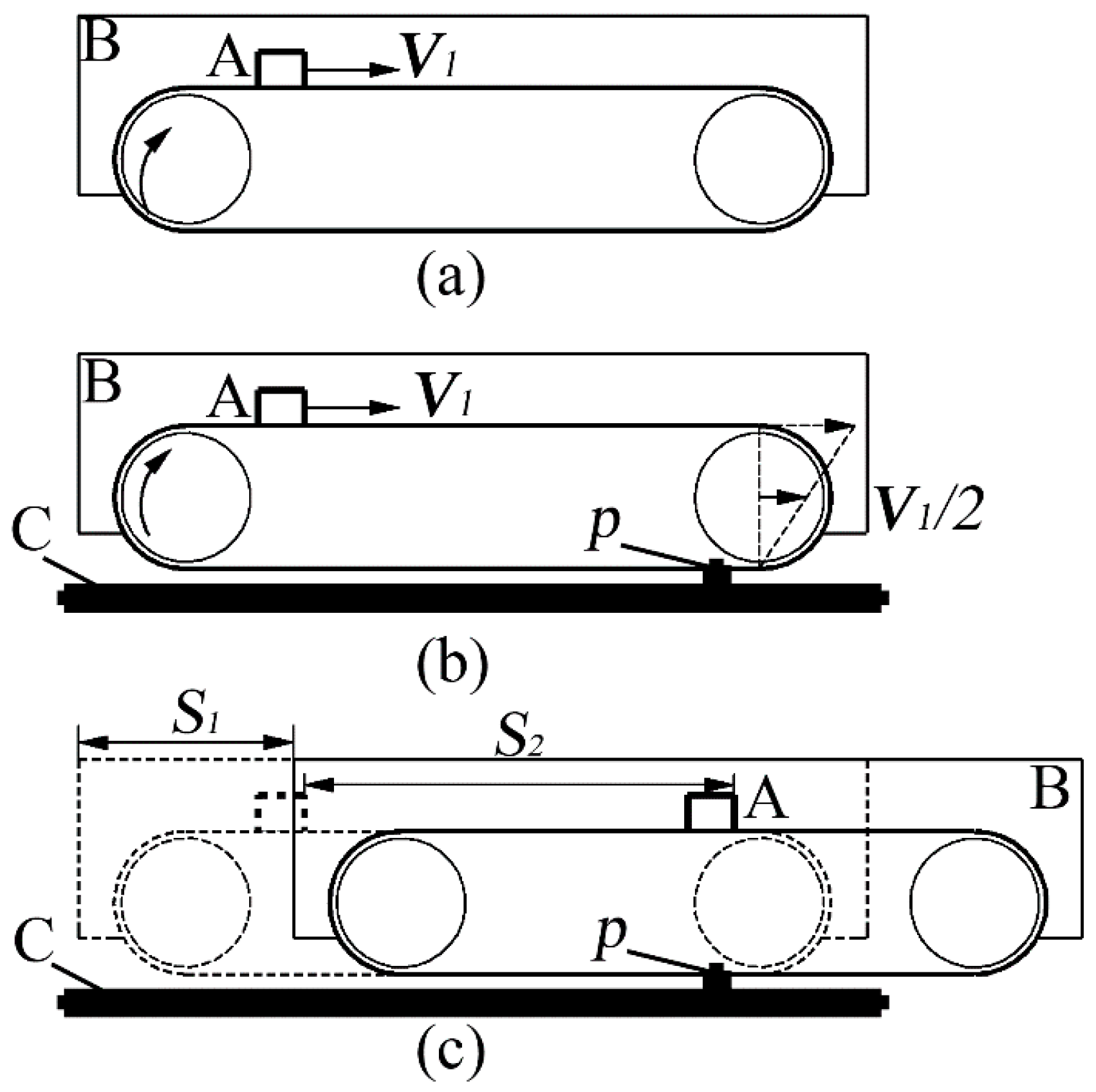
On the AODF, the working space of the rapier robot should exceed the width of the “cloth”, i.e., cover both ends of the adapter port side. At the same time, the dimensions must be as small as possible while satisfying the aim of the work. It can be observed from Figure 10a that the timing belt transmission fixed to plate B allows the object A fixed to the belt to move to the right at the same speed (V1) as the belt. If the belt is fixed at the p-point position on plate C (Figure 10b), the timing belt transmission on plate B continues to be driven at the same speed V1, and object A fixed to the belt can obtain the same speed V1 to the right. Through motion analysis, plate B moves to the right at the speed, V1/2. When plate B moves to the right by distance S1 with respect to plate C (Figure 10c), object A also moves to the right by distance S1 with respect to plate B, and object A moves to the right by a distance S2 = 2S1 with respect to plate C.
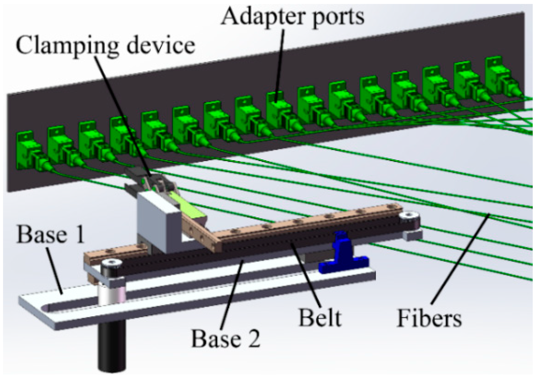
As shown in Figure 10, object A is viewed as the end-gripping device for the cross-connect operation, and the designed rapier robot is shown in Figure 11. The double-layer telescopic structure can obtain nearly twice the working stroke of the body, which is located in the shed after shedding in a random sequence. Plates C and B in Figure 10 correspond to the plates Base 1 and Base 2 in Figure 11, respectively. Plate Base 1 is fixed on the distribution frame, and plate Base 2 linearly reciprocates on plate Base 1 along the linear guide on plate Base 1. The actuator linearly reciprocates on plate Base 2 along the linear guide on plate Base 2, and the timing belt is fixed to the blue fixation device on the right side of plate Base 1. When the motor on plate Base 2 drives the timing belt, plate Base 2 moves while the movement of the actuator is driven.
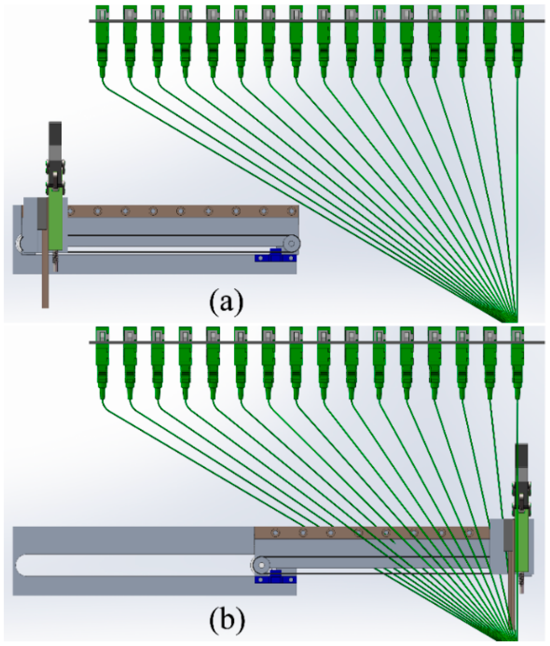
In Figure 11, the 16 adapter ports are 300 mm wide. The rapier robot has a length of 200 mm and can reach 340 mm through the double-layer telescopic device and cover the width of 16 adapter ports. This is also the reason why the position of the aforementioned fiber storage containers is set on the side of the adapter ports (Figure 5b). Figure 12 shows the states of full contraction and full extension of the rapier robot.
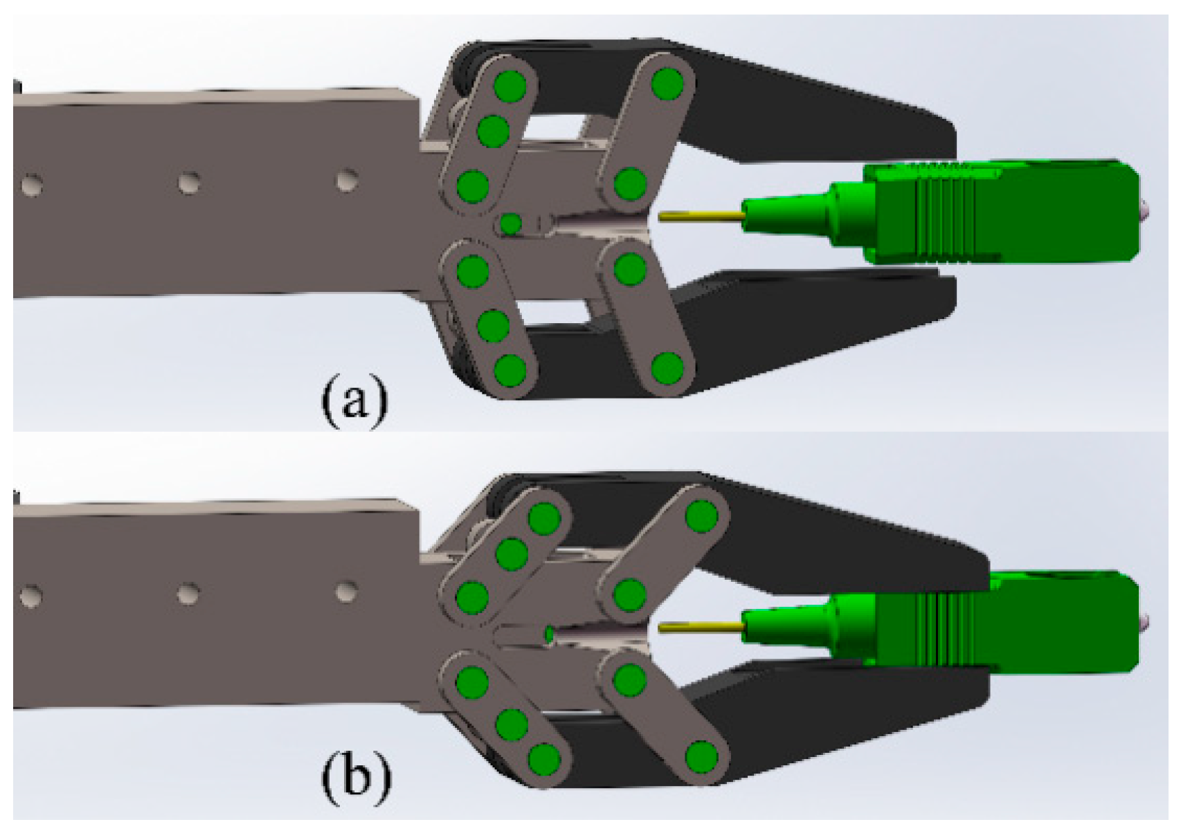
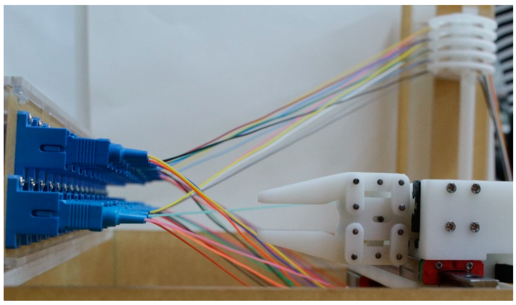
In order to ensure the stability of the clamping, the clamping action of the clamping device is designed to clamp in parallel, and the claw piece can be smoothly fitted with the type SC (Subscriber Connector) connector. At the same time, the elongated structure also facilitates movement of the clamping device between the compact adapter ports panel. Figure 13 shows the two states of loosening and clamping of the clamping device that are suitable for the SC connector. The allowable insertion force and allowable pull-out force of the SC are described in the Standards Publication [31], with a maximum of 19.6 N. After testing, the clamping device we designed can provide a clamping friction of more than 25 N for the SC connector.
5. Cross-Connect Described by Petri Net
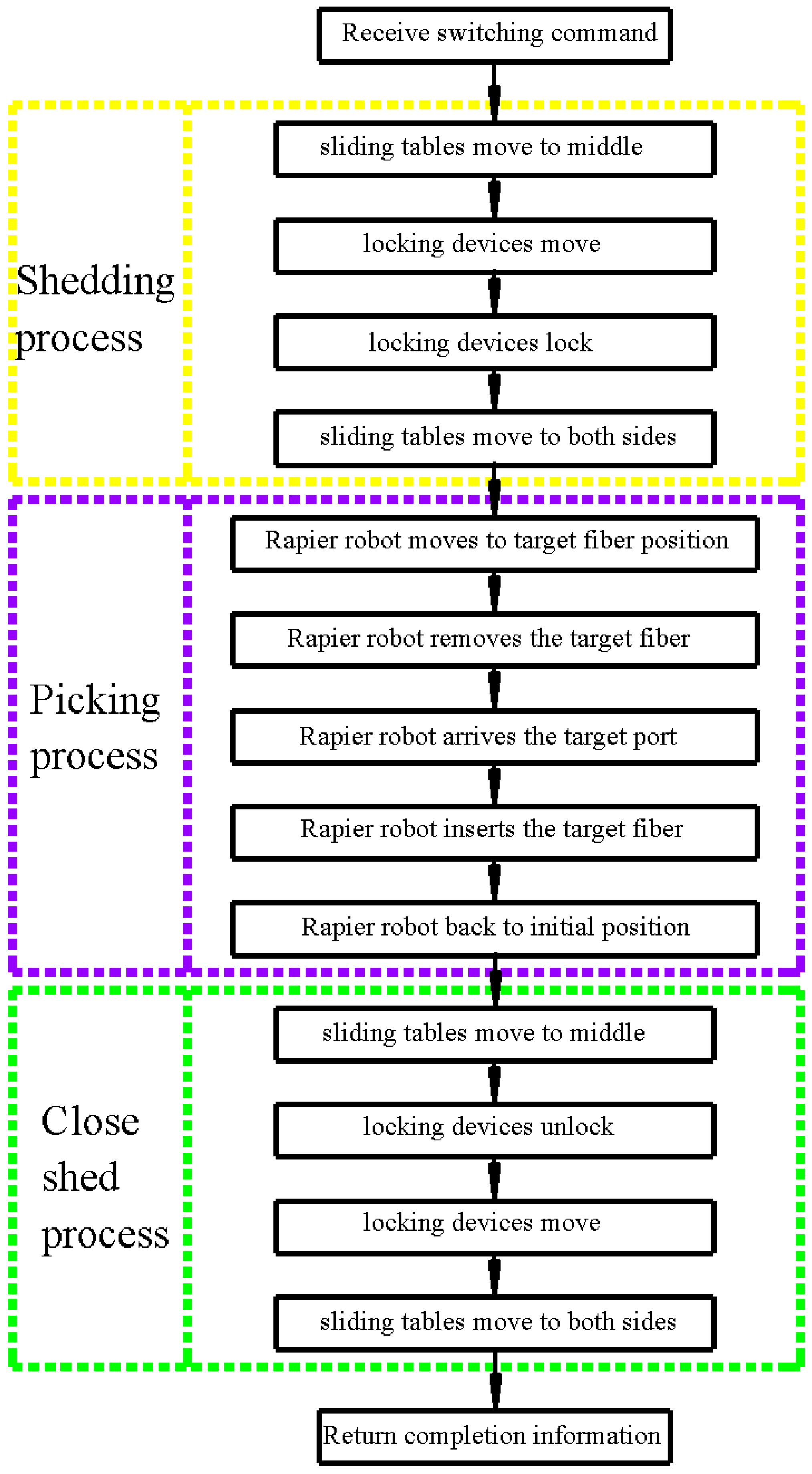
When the AODF receives the remote switching command, the shedding mechanisms perform the shedding action to enlarge the distance between the fibers first, then the rapier robot does the picking action to remove the fiber from current port and move it to the target port, the shedding mechanism closes the shed, and finally returns the completion information. The AODF workflow can be seen in Figure 14. In the system, the locking device and the rapier robot have multiple positions, so we chose absolute encoders in the prototype to record the corresponding movement position. The rest of the movement has only two states, so each uses two sets of photoelectric switches as detection devices, and the AODF uses an industrial personal computer as the controller of the prototype.
Petri nets (PNs) have been widely applied, modelled, and evaluated in industrial systems. Petri nets are simple, highly flexible, and effective tools for the modelling and analysis of discrete event systems. This method can describe the structure of the system and simulate the operation of the system. Regardless of whether it is complicated or not, it is executed by graphic or matrix representation.
A Petri net is composed of two types of nodes that represent conditions (or states) and transitions that represent events, which are interconnected by directed arcs. Formally, a basic net is a graph represented by the 4-tuple N = (P, T, F, M0), P ∪ T ≠ ∅, P ∩ T = ∅, where P is a finite set of places, T is a finite set of transitions, F ⸦ (P × T) ∪ (T × P) is a finite set of arcs, sets of input and output places of a transition are defined as •F ∪ F• = P ∪ T, and M0 is an initial marking of the net.
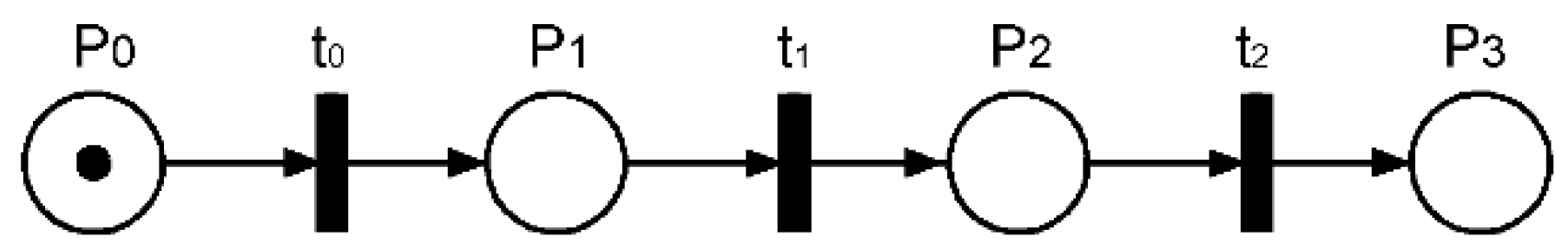
It can be observed from the above that the switching method for simulating the weft insertion of the rapier loom undergoes a significant state change between steps, which can be viewed as discrete events described by the basic PNs, as shown in Figure 15. The places are in state P0 before switching, in state P1 during the shedding operation, in state P2 during the weft insertion operation, and in state P3 during the closing shed (i.e., the state of completing the switching), and the transitions are performing the shedding action t0, the weft insertion action t1, and the closing shed action t2.
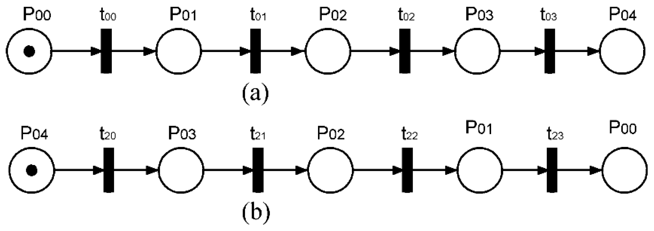
The Petri net in Figure 15 describes the entire process of switching, and each of these transitions can be divided into subnets. As observed from the above information, the shedding, picking, and closing shed can be described by one subnet. In Figure 15, t0 indicates the shedding action, t2 indicates the closing action, and they are mutually reversible. The state of the action and the action performed are shown in Table 1, the Petri net of the shedding process is shown in Figure 16a, and the Petri net of closing the shed is shown in Figure 16b.
The shedding, picking, and closing shed in the loom are cyclical processes. During switching, the cycle action of the weft insertion process is different. The closing shed, after the completion of the weft insertion, is not completely a mirror image of the shedding process because when the shed is closed, the locking device locks the fiber storage container and is integrated with the sliding table, whereas in the shedding process, these are independent movements. The Petri net of the shed closing process is shown in Figure 16b, in which the places are the same with the shedding action, but through the opposite transitions. The transitions are such that the sliding table moves to the reset position t20, the locking device performs the unlocking operation t21, the locking device moves the initial state t22, and the shedding device moves the initial state t23.
The upper and lower shedding mechanisms can move at the same time or at different times. In the 1–n fibers, when the target fiber is 1(n), only the lower side (upper side) of the shedding mechanism is required to complete the shedding operation.
As shown in Figure 7, the locking device can move on the sliding table, move along with the sliding table, or move independently. The Petri net in Figure 16a shows that the locking device moves along with the sliding table first, then moves independently to the target position. After the locking device is unlocked, the Petri net in Figure 16b shows it first moves to the initial position on the sliding table and then moves along with the sliding table.
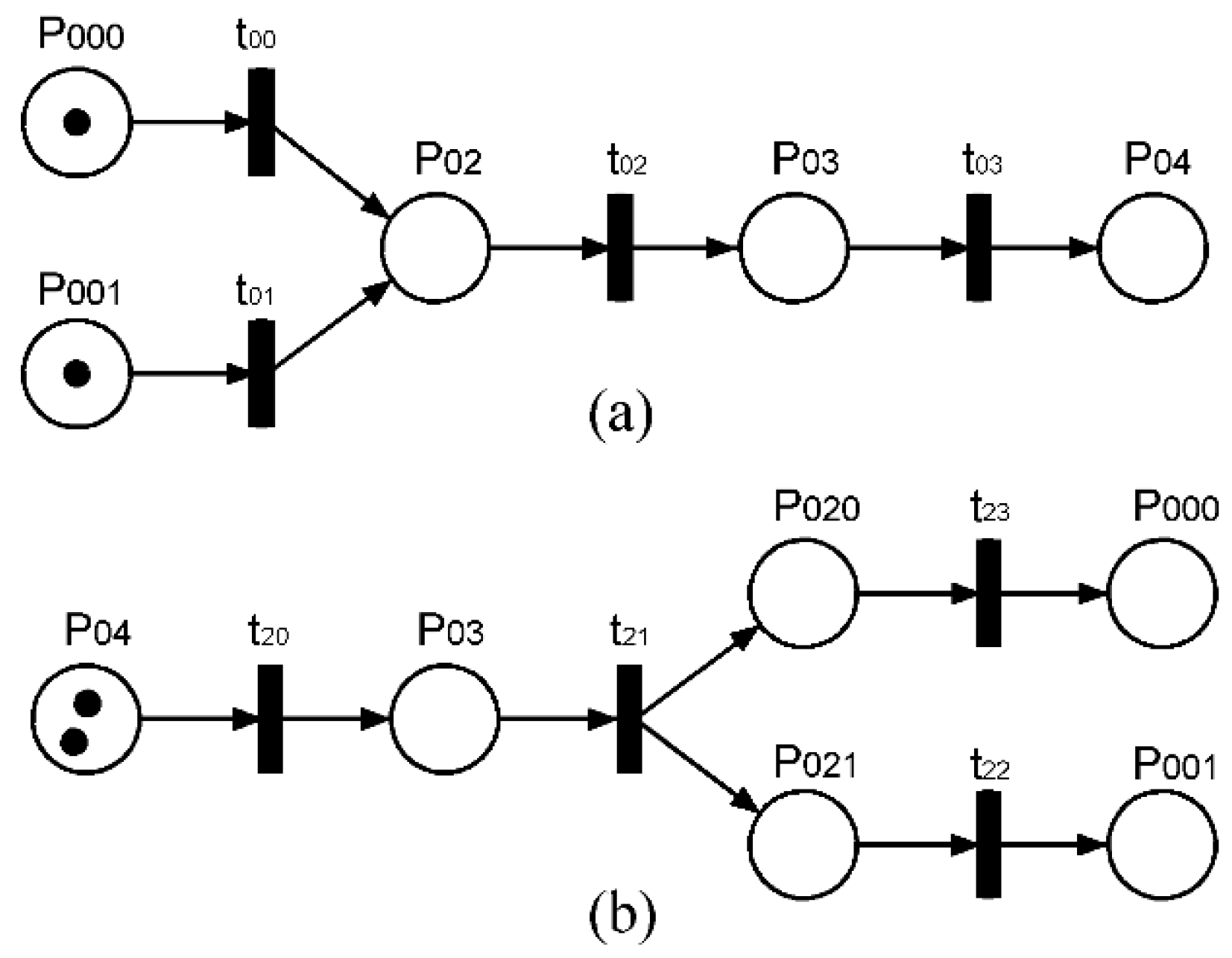
If the locking device moves independently to the initial (target) position on the sliding table while the sliding table is moving, the Petri nets indicating the shedding and the closing are shown in Figure 17a,b, respectively. The sliding table and the locking device move simultaneously, so their initial state is considered separately. In the shedding process, the places are state P000 of the sliding table before the shedding operation and state P001 of the locking device before the shedding operation. In the process of closing the shed, the locking device locks the fiber storage containers and is integrated with the sliding table first, then they can move separately after unlocking; the places are state P020 of the sliding table after unlocking and state P021 of the locking device after unlocking.
In Figure 15, transition t1 indicates the shedding action. The process of performing the weft insertion using the rapier robot can be disassembled into multiple steps. The state of the action and the action performed are shown in Table 2. The Petri net description of the entire process is shown in Figure 18. The process of weft insertion can be treated as a cyclical action process of the rapier robot starting from the initial state and finally returning to the initial state.
The Petri nets are used to represent the entire cross-connect process, and the process is decomposed into subnets for representation, making the design of the control system clearer and easier.
6. Prototype Design and Experiment
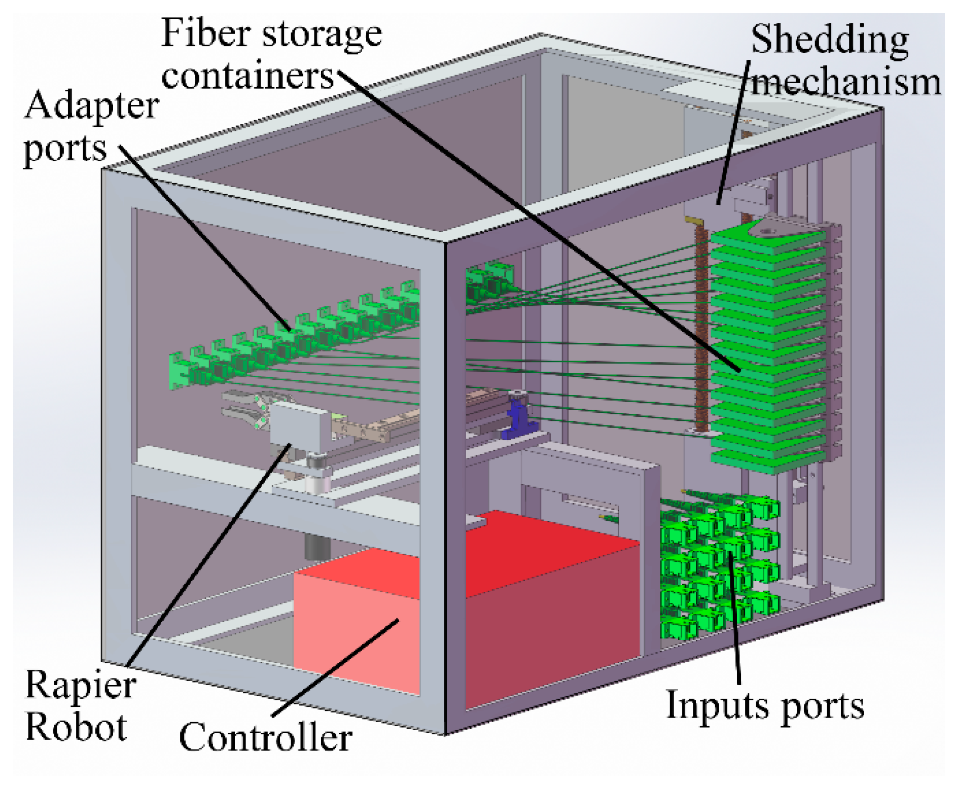
The rapier robot moves in the plane of the adapter ports, enabling the connector to be unplugged or plugged in and to stabilize gripping of the connector while it moves in the shed. By combining the adapter port panel, the shedding mechanism, the input and output, the corresponding controller, and the frame, an AODF prototype was constructed that imitates the picking of the rapier loom. The three-dimensional model is shown in Figure 19. The outer dimensions of the prototype are 42 cm long by 27 cm wide by 31 cm tall.
Using SC simplex adapters can achieve the same insertion loss and the same return loss as the standard patch panel. There is enough space in the model to set up the fiber end face cleaning device, and it was necessary to clean the end face during reconfiguration to produce low-loss connections.
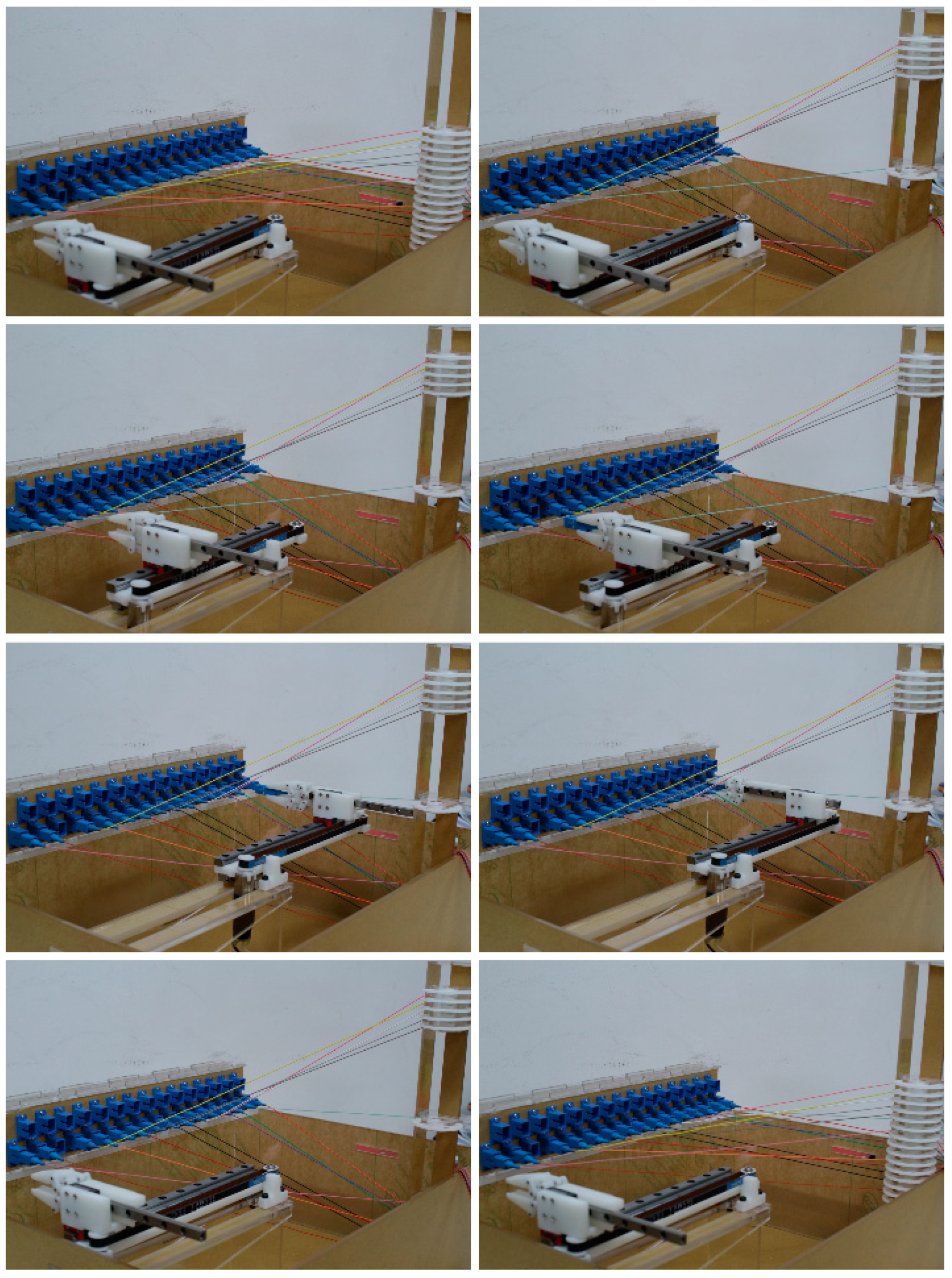
In the demonstration system, the input terminals are SC simplex adapters and a bend-insensitive single-mode fiber [32]. We created an experimental model of the prototype and a series of switching tests were performed on the model. Figure 20 shows a random sequence of fiber 06 switching from port 03 to port 15, and the fibers on the left to right port are 07, 15, 06, 02, 11, 05, 12, 04, 14, 13, 03, 01, 09, 10, 00, and 08, where 00 is the target port of the switching and no fiber is inserted. When the AODF receives the cross-connect command, the shedding mechanism first performs a shedding operation according to the command such that the gap on both sides of the target fiber is sufficient for the rapier robot to enter. The rapier robot extends from the shed to the current position of the target fiber, removes the fiber and moves to the target port, inserts the fiber into the target port, and exits the shed. The shedding mechanism closes the shed inward to complete the switching operation.
According to the higher always on top method described by Yang et al. [28], fibers 01–05 are above fiber 06, and fibers 07–15 are below fiber 06. During the switching process, fiber 06 passes below fibers 01–05 and crosses over fibers 08–14. Every time the robot crosses over the fiber, two handover actions are required with the commutation device. The entire process requires seven times handover actions. In the experiment with the prototype based on the higher always on top method, the handover actions occupy most of the switching process time. Assuming that the robot has the same speed on the AODF, its motion time is Tr, whereas a typical shedding time is about 12 seconds, and the time for a handover action in the previous higher always on top method prototype is about 10 seconds. The total time of the higher always on top method is TH = Tr + 7 × 10 s, whereas the time for the shedding and picking method is TS = Tr + 12 s.
According to the switching test on the experimental model prototype, the cross-connect method proposed in this paper can realize rapid switching, but the smaller capacity of the prototype is a weakness. As observed from Figure 6, the factors that restrict the capacity of the AODF are primarily the size of the rapier robot and the size of the fiber storage container. If the size of the rapier robot is reduced and the required shedding distance in the Z-direction is reduced, i.e., the height of the shed is reduced, thereby reducing the height of the AODF, the reduction in the size of the fiber storage container directly reduces the height of the AODF.
To reduce the outer dimensions of the device, we configured a second layer port on the adapter port side of the model prototype aligned with the gap between the first layer ports, with 16 ports on the first layer and 15 on the second layer. A random shedding simulation was performed on the two-layer model, as shown in Figure 21. The shed size satisfies the existing rapier robot for weft insertion. However, to operate the upper and lower connectors, in addition to the current degrees of freedom in the X- and Y-directions, it was necessary to design a Z-direction freedom.
Referring to the gap configuration of the adapter ports, the gap of the fiber storage containers can be configured to increase the density of the fiber when the size of the fiber storage container is fixed. In the three-dimensional model of Figure 19, the gap configuration of two sets of fiber storage containers was tested, as shown in Figure 22. The two circles in the figure represent two sets of fiber storage containers, indicated by the solid and dashed lines of the fibers that denote the possible connection of the fiber status. It can be observed from Figure 22 that the double column design of the fiber storage containers is feasible. The configuration of the double column and the double layer of the gap still satisfy the spatial relationship of noncoplanar lines of the 1-D to 1-D form, and the capacity is doubled while the overall size is generally the same. Similarly, in the case of a single-layer adapter ports, the double column design of the fiber storage containers can also reduce the outer dimensions.
7. Conclusions
In this paper, we propose a cross-connect method that imitates the weft insertion of the rapier loom, and we designed the corresponding shedding mechanism and the rapier and produced a model prototype. PNs were used to analyze the entire switching process, clarifying the switching process. An experiment on the prototype was conducted to verify the cross-connect method, which greatly improved the switching speed. Compared with the higher always on top method, the switching time of this method was faster. In this method, the adapter port panel can be set to many layers, but the “noncoplanar lines” condition must be satisfied. The system is small and can be easily assembled into the existing communication cabinet. The structure is simple, the motors used are relatively small, and the power consumption of the whole machine is also low. Future research is planned to optimize this approach and the corresponding mechanisms.
Author Contributions
Funding acquisition, S.W.; Methodology, Z.Y. and Y.S.; Resources, L.G.; Supervision, L.G.; Validation, Z.Y. and Y.S.; Writing—original draft, Z.Y.; Writing—review & editing, S.W., L.G., and Y.S. All authors have read and approved the final paper.
Funding
This work was supported by the Beijing Municipal Natural Science Foundation under Grant L172031, the National Natural Science Foundation of China under Grant 51375059 and Grant 61105103, the National High Technology Research and Development Program of China under Grant 2011AA040203, and the Seed Program of the Beijing University of Posts and Telecommunications Information Network Industry Research Institute.
Conflicts of Interest
The authors declare that there are no conflicts of interest.
References
- Takai, H.; Yamauchi, O. Optical fiber cable and wiring techniques for fiber to the home (FTTH). Opt. Fiber Technol. 2009, 15, 380–387. [Google Scholar] [CrossRef]
- Botha, M.I. Modelling and Simulation Framework Incorporating Redundancy and Failure Probabilities Fir Evaluation of a Modular Automated Main Distribution Frame. Master’s Thesis, University of Pretoria, Pretoria, South Africa, October 2012. [Google Scholar]
- Chen, D.Z. Method and Apparatus for Providing an Automated Patch Panel. U.S. Patent US8175425, 8 May 2012. [Google Scholar]
- Cuda, D.; Giaccone, P.; Montalto, M. Design and control of next generation distribution frames. In Proceedings of the IEEE International Conference on High PERFORMANCE Switching and Routing, Cartagena, Spain, 4–6 July 2011; Volume 56, pp. 115–120. [Google Scholar]
- Takeuchi, Y.; Zhang, Q.; Lu, H. Optical Switch. U.S. Patent US2013/0259422A1, 3 October 2012. [Google Scholar]
- Mizukami, M. Fiber-handling robot and optical connection mechanisms for automatic cross-connection of multiple optical connectors. Opt. Eng. 2013, 52, 076116. [Google Scholar] [CrossRef] [Green Version]
- Kewitsch, A.S. Large scale, all-fiber optical cross-connect switches for automated patch-panels. J. Lightwave Technol. 2009, 27, 3107–3115. [Google Scholar] [CrossRef]
- Mizukami, M.; Makihara, M.; Sasakura, K. Development of automated optical fiber cross-connect equipment. NTT Tech. Rev. 2004, 2, 63–67. [Google Scholar]
- Lecoy, P. Fibre-Optic Communications; WILEY: Hoboken, NJ, USA, 2010; pp. 121–140. [Google Scholar]
- Decusatis, C. Handbook of Fiber Optic Data Communication: A Practical Guide to Optical Networking, 4th ed.; Academic Press: Waltham, MA, USA, 2014; pp. 291–316. [Google Scholar]
- Avrahami, Z.; Arol, J. A Method Device Assembly and System for Facilitating the Interconnection of Communication Bearing Cables. Patent WO/2011/013090, 3 February 2011. [Google Scholar]
- Pnini, B.; Ganor, Z.; Cohen, R.; Eizenshtat, M. Optical Crossbar Switch. U.S. Patent US8107779B2, 31 January 2012. [Google Scholar]
- Kewitsch, A.S. Scalable and Modular Automated Fiber Optic Cross-Connect Systems. U.S. Patent US8068715B2, 29 November 2011. [Google Scholar]
- Safrani, A.; Gottlieb, M. Mechanical Optical Switch. U.S. Patent US7813600B1, 12 October 2010. [Google Scholar]
- Huang, X.; Bie, H.; Yang, B.; Guo, Y. Fiber Patch Cord Apparatus, Port Panel, and Fiber Patch Cord System. U.S. Patent US9535220B2, 3 January 2017. [Google Scholar]
- Wei, S.; Guo, L.; Yang, Z.; Han, Z.; Wang, C. Automatic Network Cable Distributing Device and Distributing Method. CN102938865A, 15 July 2015. [Google Scholar]
- Hwang, R.B.; Yang, S.C.; Huang, H.T. Beam steering antenna structure. IEEE Trans. Device Mater. Reliab. 2015, 13, 272–276. [Google Scholar]
- Blanche, P.-A.; LaComb, L.; Wang, Y.; Wu, M.C. Diffraction-Based Optical Switching with MEMS. Appl. Sci. 2017, 7, 411. [Google Scholar] [CrossRef]
- Jing, M. Woven Structure and Design; China Textile & Apparel Press: Beijing, China, 2014; pp. 6–30. [Google Scholar]
- Hayavadana, J. Woven Fabric Structure Design and Product Planning; CRC Press: Boca Raton, FL, USA, 2015. [Google Scholar]
- Rouette, H.K.; Lindner, A.; Schwager, B. Encyclopedia of Textile Finishing; Springer: Berlin/Heidelberg, Germany, 2000. [Google Scholar]
- Adanur, S. Handbook of Weaving; Crc Press: Boca Raton, FL, USA, 2000; pp. 263–290. [Google Scholar]
- Gokarneshan, N. Fabric Structure and Design; New Age International Limited, Publishers: New Delhi, India, 2004; pp. 1–10. [Google Scholar]
- Wilson, J. Handbook of Textile Design; CRC Press: Boca Raton, FL, USA, 2001. [Google Scholar]
- Lima, M.; Zabka, P. Design and analysis of conjugate cam mechanisms for a special weaving machine application. In Proceedings of the International Conference on Innovations, Recent Trends and Challenges InMechatronics, Mechanical Engineering and New High-Tech Products Development, Bucharest, Romania, 23–24 September 2010. [Google Scholar]
- Badawi, S. Development of the Weaving Machine and 3d Woven Spacer Fabric Structures for Lightweight Composites Materials. Ph.D. Thesis, TU Dresden, Saxony, Germany, July 2007. [Google Scholar]
- Gokarneshan, N.; Alagirusamy, R. Weaving of 3d fabrics: A critical appreciation of the developments. Text. Prog. 2009, 41, 1–58. [Google Scholar] [CrossRef]
- Zheng, Y.; Shimin, W.; Lei, G. Non-Winding AODF Cross-Connect Method Based on the Spatial Relationship of Non-Coplanar Lines. IEEE Access 2018, 6, 29054–29066. [Google Scholar]
- Tanton, J.S. Encyclopedia of Mathematics; Facts On File: New York, NY, USA, 2005; pp. 49–55. [Google Scholar]
- Domenico, P.; Jeffrey, C.T. Grasping. In Springer Handbook of Robotics; Bruno, S., Oussama, K., Eds.; Springer: Berlin/Heidelberg, Germany, 2008; pp. 671–700. [Google Scholar]
- Ministry of Information Industry of the People’s Republic. YD/T 1272.3: Optical Fiber Connector—Part 3: Type SC Connector Family; Post & Telecom Press: Beijing, China, 2015.
- Yao, L.; Birks, T.A.; Knight, J.C. Low bend loss in tightly-bent fibers through adiabatic bend transitions. Opt. Express 2009, 17, 2962–2967. [Google Scholar] [CrossRef] [PubMed]
- Yasuda, G. Distributed control of industrial robot systems using Petri net based multitask processing. In International Conference on Intelligent Robotics and Applications; Springer: Berlin/Heidelberg, Germany, 2010; Volume 6425, pp. 32–43. [Google Scholar]
- Yasuda, G. Discrete Event Net Based Modeling and Control System Design for Real-Time Concurrent Control of Multiple Robot Systems. Intell. Control Autom. 2012, 3, 132–139. [Google Scholar] [CrossRef]
- Wisniewski, R. Dynamic partial reconfiguration of concurrent control systems specified by petri nets and implemented in xilinx fpga devices. IEEE Access 2018, 6. [Google Scholar] [CrossRef]
Figure 1.
Weaving process diagram for a single rapier loom.

Figure 2.
Manual switching process.

Figure 3.
Schematic diagram of the shed.

Figure 4.
Model of a sequence of a one-dimensional (1-D) to 1-D form.

Figure 5.
Two positions of the fiber storage containers and the adapters in the X-axis direction. (a) Fiber storage containers in the middle; (b) fiber storage containers on one side. The following parts are labeled: (R1) the length of the rapier robot, (R2) the length of the rapier robot.
Figure 5.
Two positions of the fiber storage containers and the adapters in the X-axis direction. (a) Fiber storage containers in the middle; (b) fiber storage containers on one side. The following parts are labeled: (R1) the length of the rapier robot, (R2) the length of the rapier robot.

Figure 6.
Position of the fiber storage containers and adapter ports’ sides in the Z-axis direction.
Figure 6.
Position of the fiber storage containers and adapter ports’ sides in the Z-axis direction.

Figure 7.
Composition of the shedding mechanism.

Figure 8.
Shedding process in the shedding mechanism. (a) The initial state; (b) sliding tables move to the middle; (c) locking devices move and lock; (d) sliding tables move to both sides to form the shed.
Figure 8.
Shedding process in the shedding mechanism. (a) The initial state; (b) sliding tables move to the middle; (c) locking devices move and lock; (d) sliding tables move to both sides to form the shed.

Figure 9.
Shedding mechanism: the close shed process. (a) The shedding state; (b) sliding tables move to close shed; (c) locking devices unlock; (d) sliding tables and locking devices move to initial state.
Figure 9.
Shedding mechanism: the close shed process. (a) The shedding state; (b) sliding tables move to close shed; (c) locking devices unlock; (d) sliding tables and locking devices move to initial state.

Figure 10.
Rapier robot double-layer telescopic schematic. (a) Basic timing belt transmission structure; (b) double-layer telescopic speed schematic; (c) double-layer telescopic displacement schematic. The following parts are labeled: (V1) belt speed, (A) object A, (B) plate B, (C) plate C, (p) fixed point of the belt, (S1) moving distance of plate B, and (S2) moving distance of object A.

Figure 11.
Three-dimensional model of the rapier robot.

Figure 12.
Working range diagram of the rapier robot. (a) Full contraction state; (b) full extension state.
Figure 12.
Working range diagram of the rapier robot. (a) Full contraction state; (b) full extension state.

Figure 13.
Two states of the rapier robot’s clamping device: (a) loosening; (b) clamping.

Figure 14.
Automatic optical distribution frame (AODF) working flow chart.

Figure 15.
Petri net that describes the cross-connect process.

Figure 16.
The Petri nets of the shedding process and closing the shed when the locking device and the sliding table move separately. (a) The net of transitions t0; (b) the net of transitions t2.
Figure 16.
The Petri nets of the shedding process and closing the shed when the locking device and the sliding table move separately. (a) The net of transitions t0; (b) the net of transitions t2.

Figure 17.
The Petri nets of the shedding process and closing the shed when the locking device and the sliding table move simultaneously. (a) The net of transitions t0; (b) the net of transitions t2.
Figure 17.
The Petri nets of the shedding process and closing the shed when the locking device and the sliding table move simultaneously. (a) The net of transitions t0; (b) the net of transitions t2.

Figure 18.
Petri net of the picking process.

Figure 19.
Drawing of the AODF prototype.

Figure 20.
Cross-connect process of a random sequence.

Figure 21.
Double-port shed diagram.

Figure 22.
Double fiber storage containers: column connect diagram.


Table 1.
Table of places and transitions in the shedding process and closing the shed.
| Places | P00 | The position of sliding table before the shedding operation |
| P01 | The sliding table is in contact with the fiber storage containers | |
| P02 | The locking device reaches the locking position | |
| P03 | The locking device completes locking | |
| P04 | The sliding table completes the shedding process | |
| Transitions | t00 | The sliding table moves |
| t01 | The locking device moves | |
| t02 | The locking device performs the locking operation | |
| t03 | The sliding table moves in the shedding direction | |
| t20 | The sliding table moves to the middle | |
| t21 | The locking device performs the unlocking operation | |
| t22 | The locking device moves | |
| t23 | The sliding table moves |
Table 2.
Table of places and transitions (Tr) in the picking process.
| Places | P10 | The rapier robot on the initial position |
| P11 | Rapier robot arrives the target fiber position | |
| P12 | Clamping device arrives target fiber | |
| P13 | Clamping device clamps the target fiber | |
| P14 | Clamping device pulls out the target fiber | |
| P15 | Rapier robot moves to the target port | |
| P16 | Clamping device inserts the target fiber | |
| P17 | Clamping device releases the target fiber | |
| P18 | Clamping device back to the initial position | |
| Transitions | t10 | Rapier robot moves |
| t11 | Clamping device moves | |
| t12 | Clamping device clamps | |
| t13 | Clamping device moves | |
| t14 | Rapier robot moves | |
| t15 | Clamping device moves | |
| t16 | Clamping device release | |
| t17 | Clamping device moves | |
| t18 | Rapier robot moves |
© 2019 by the authors. Licensee MDPI, Basel, Switzerland. This article is an open access article distributed under the terms and conditions of the Creative Commons Attribution (CC BY) license (http://creativecommons.org/licenses/by/4.0/).
Share and Cite
MDPI and ACS Style
Wei, S.; Yang, Z.; Guo, L.; Song, Y. A New Type of AODF Based on an Imitation of the Weft Insertion of a Rapier Loom. Electronics 2019, 8, 157. https://doi.org/10.3390/electronics8020157
AMA Style
Wei S, Yang Z, Guo L, Song Y. A New Type of AODF Based on an Imitation of the Weft Insertion of a Rapier Loom. Electronics. 2019; 8(2):157. https://doi.org/10.3390/electronics8020157
Chicago/Turabian StyleWei, Shimin, Zheng Yang, Lei Guo, and Yuan Song. 2019. "A New Type of AODF Based on an Imitation of the Weft Insertion of a Rapier Loom" Electronics 8, no. 2: 157. https://doi.org/10.3390/electronics8020157
Note that from the first issue of 2016, this journal uses article numbers instead of page numbers. See further details here.