Cascade Second Order Sliding Mode Control for Permanent Magnet Synchronous Motor Drive


Division of Engineering, Saint Mary’s University, Halifax, NS B3H 3C3, Canada
Electronics 2019, 8(12), 1508; https://doi.org/10.3390/electronics8121508
Submission received: 1 November 2019
/
Revised: 3 December 2019
/
Accepted: 5 December 2019
/
Published: 9 December 2019
(This article belongs to the Special Issue Advanced Control Systems for Electric Drives)
Abstract
:This paper presents a cascade second-order sliding mode control scheme applied to a permanent magnet synchronous motor for speed tracking applications. The control system is comprised of two control loops for the speed and the armature current control, where the command of the speed controller (outer loop) is the reference of the q-current controller (inner loop) that forms the cascade structure. The sliding mode control algorithm is based on a single input-output state space model and a second order control structure. The proposed cascade second order sliding mode control approach is validated on an experimental permanent magnet synchronous motor drive. Experimental results are provided to validate the effectiveness of the proposed control strategy with respect to speed and current control. Moreover, the robustness of the second-order sliding mode controller is guaranteed in terms of unknown disturbances and parametric and modeling uncertainties.
1. Introduction
Permanent magnet synchronous motors (PMSM) have been broadly deployed in variable speed drives due to their efficiency, high power density and fast dynamics. However, the control efficiency of PMSM drives is affected by parametric inaccuracies, load disturbances and uncertainties in real applications. Furthermore, they are nonlinear multivariable systems with modeling uncertainties and parameters changing during operation.
High performance control of PMSMs is difficult to attain, using model-based methods, due to the above drawbacks. Therefore, various robust and advanced control methods have been conducted to improve the PMSM efficiency. In [1], an adaptive speed regulator was designed with no information about the PMSM parameters, the load and the torque values. Another adaptive control method was investigated in [2] through adapting the feedforward compensation gain with respect to the identified inertia and an extended state observer was used to estimate both the states and the disturbances simultaneously. A disturbance torque estimation and nonlinear control was developed in [3] and predictive control strategy in [4]. Similar to other works, tracking performance and robustness were performed through disturbance estimation, which alleviate the computation burden of such controllers [5,6].
High order sliding mode control (SMC) has emerged as an efficient control method due to its insensitivity with respect to system inaccuracies and unknown disturbances. Furthermore, it has advantages over the traditional SMC to overcome the chattering problems [7,8]. Different second-order SMC strategies have been developed for PMSMs. In [9] and [10], SMC-based disturbance observer, for uncertainties compensation, was proposed to reduce chattering and designed for the speed control loop. In [11], a second order SMC was presented as a direct torque and flux controller for PMSM without chattering. In [12], a second order SMC algorithm, using proportional-plus-integral sliding plane, was developed to improve the tracking and robustness performance compared to conventional first order SMC. In [13], a second order SMC was designed using an integral manifold for the speed control from the mechanical equation of the permanent magnet synchronous generator-based wind energy system. Other strategies, related to SMC applied to deferent drives and systems, are available in the literature [14,15,16,17,18]. In [19], a feedback linearization was combined with optimization to deal with parametric changes and applied to a pendulum like a robot. In [20], a standard SMC scheme was derived from the SISO case and used as a decoupled input-to-flat-output model for a robot manipulator with good performance. Despite the good performance of such control strategies, it is difficult to assess the behavior of SMC strategies when dealing with both mechanical and electrical models of the PMSM system. In general, the SMC method is applied to the speed equation of the machine and the conventional vector control, PI-based method, which is used for the electrical equation for the current control loop due to the computational burden and implementation limitation when applying advanced controllers [13]. This matter will be explored in this work by considering both mechanical and electrical systems to develop a cascade structure of an advanced control strategy and using the powerful Opal-RT real time experimental system for control implementation. Furthermore, this work deals with a cascade structure and interaction between different SMC controllers for multivariable control, which will help in understanding the implementation issues of such controller in the area of multivariable control. The second-order SMC scheme provides higher capabilities for dealing with nonlinearities and uncertainties compared with conventional control methods, such as PI control and linearization control, as changes in the system do not require tuning of its parameters or adding mechanisms to deal with parametric uncertainties.
In this paper, a second-order SMC is designed for multivariable control, in a cascade scheme, of PMSM drive. The output tracking error dynamic, for rotational speed and d-q components of the current, is modelled under a single input-output state space model and decoupled by considering the nonlinear terms in new variable inputs. Furthermore, the unknown load torque effect is rejected by the proposed second-order SMC through integral action in the controller without the need for observing the load torque or identifying the inertia seen by the rotor shaft. In general, any other uncertainties in the mechanical and electrical systems of the PMSM, such as unmodeled quantities, parameters’ variations and external disturbance, will be compensated by the proposed control scheme, which constitutes the contribution of this work compared to [9,10,11,12,13]. The proposed controller for speed and current tracking is robust against parametric variations and uncertainties in the system.
2. PMSM Model
The PMSM model, in the d-q rotating reference frame, is described by
where, isd is the d-axis of the stator current; isq is the q-axis of the stator current; vsd is the d-axis control voltage; vsq is the q-axis control voltage; is the permanent magnet magnetic flux linkage; p is the poles pairs number; R is the stator resistance; Ld is the d-axis of the inductance of the stator winding; Lq is the q-axis of the inductance of the stator winding; ωr is the rotational speed; J is the moment of inertia; f is the viscous friction coefficient; and TL is the load torque.
The variables to be controlled are the rotor speed ωr and the d-axis of the stator current isd to track external references and the q-axis of the stator current isq to track a reference produced by the outer loop of speed control. Furthermore, the load torque is an unknown disturbance and will be compensated by the proposed controller.
3. Cascade Second-Order SMC
3.1. Control Developement
The state space model, based on single input single output (SISO), has the following expression
where, x is the state variable, v is the input variable and d is an unknown bounded disturbance.
The control objective is to ensure a zero steady state error such as
where, xref is the reference, and e is the tracking error.
The tracking error dynamic is carried out using (2) and (3) and expressed by
where, u is the new control input.
The new control input is expressed by
Then, let us consider the second-order SMC for perturbation elimination [8,18]
where, k1 and k2 are positive constants, and sgn is the switching function
Finally, from (5) and (6), the command v in (2) for regulating x to track the reference xref is provided by
The stability of the second order SMC (8) applied to (4) to ensure e(t)→0 can be demonstrated in a similar manner as in [8].
The advantage of the second-order SMC compared to the traditional SMC is that it takes into consideration the nonlinearities and uncertainties with better performance as it includes an integral action. It is well known that an integral action enhances the control efficiency in dealing with uncertainties.
3.2. Cascade Second Order SMC Structure
The cascade control scheme, depicted in Figure 1, includes two loops for the control systems such as: (1) the outer loop control for speed regulation provides the q-axis of the current reference applied to the inner control loop. (2) The inner loop control for current regulation that provides the voltage commands to generate the six pulses to control the DC-AC converter.
3.2.1. Outer Loop Control
The second-order SMC is developed using the motion equation. The control system provides the q-axis current as a reference for the inner loop in order to track the desired speed reference.
The motion Equation (1b) is expressed under the form (2) as
where, .
The speed tracking error dynamic is expressed by
where, is the speed tracking error, and the new control input is provided by
Therefore, the q-axis current reference based on the 2-SMC law (8) is expressed as
3.2.2. Inner Loop Control
The sliding mode control is applied to the electrical model in order to provide the components of the stator voltage which minimizes the difference between the stator current components (isd, isq) and the current references (isdref, isqref), respectively.
The electrical equation (1.a) is expressed, under the form (2), as
where, .
The input variables (vd, vq) represent the decoupling components to linearize the system (1a) and are expressed as
The current tracking error dynamics are expressed by
where, ed=isdref − isd and eq=isqref − isq are the (d, q) current tracking errors.
The new control inputs are given by
The second-order SMC for d-q current control is carried out from (14)–(16), using the control design (5)–(8), and the voltage command components are given by
3.3. Chattering Reduction
The reduction of the chattering phenomenon in the control laws (12) and (17), the sgn function is modified such as
where, represents the boundary layer thickness.
4. Robustness to Uncertainties
The PMSM dynamics are uncertain and include uncertainties such as unmodeled quantities, parametric variations, and unknown and external disturbances. Therefore, the control design must be robust to compensate all these uncertainties and enhance the tracking performance.
The PMSM limitations, related to the boundedness of the rotor acceleration and speed, the electrical-mechanical parameters in (1), and the load torque, during its operation are described by [13]
where, is the upper value of the rotor speed, andis the upper value for the rotor acceleration.
Note: the symbol “−” is used for the nominal value, Δ represents the uncertainty, and are bounded positive constants.
Stability analysis for perturbed systems, controlled by a second-order SMC, has been detailed in [8]. The asymptotic stability of the closed-loop system is guaranteed by selecting control gains that satisfy the following conditions
Let us define the system (1) with uncertainties
where, and are parametric uncertainties.
The equations in (23) are rearranged with all uncertainties included in single terms such as
where, and .
The new perturbation terms, in (24), include parametric uncertainties, unmodeled quantities and unknown disturbances. The SMC laws (12) and (17) will reject the bounded perturbations, which is one of the major characteristics of the SMC [7]. The advantage of the proposed cascade second-order SMC, compared to model based methods, such as optimal, feedback and predictive control, is that the knowledge about the load torque is not required, by measurement or estimation, and will be rejected to achieve zero steady-state tracking error.
5. Opal-RT HIL and Experimental System
The experimental system is shown in Figure 2, and the hardware connection is depicted in Figure 3. It includes a PMSM drive; speed encoder; power supply; insulated-gate bipolar transistor (IGBT) inverter; inductor line; dynamometer connected to the rotor shaft acting as a load; and data acquisition board (OP8660) with inputs for current, voltage and speed measurements and outputs for inverter pulses. The system is driven by the Opal-RT real-time simulator (OP5600). The schematic of the hardware connections between all modules is shown in Figure 4. The proposed cascade second-order SMC scheme is implemented in the Simulink/MATLAB and RT-LAB real-time simulation software environment, executed in the OP5600 and deployed to the system drive through the OP5600. The hardware in the loop (HIL) system, that includes the PMSM drive, the OP8660 and the OP5600, is illustrated in Figure 4. Details about the communication and deployment are available in [21].
6. Experimental Results and Discussions
Experiments were conducted to validate the proposed cascade second-order SMC scheme under multiple operating conditions that include tracking performance under variable speed, robustness to parametric uncertainties (electrical and mechanical), rejection of external disturbance (sudden change in the power supply voltage), and unknown load torque. The PMSM parameters are provided in Table 1. In all scenarios, the control gains, provided in Table 2, were selected by trial and error method and remain constant for all experiments. The experimental results are illustrated in Figure 5, Figure 6, Figure 7, Figure 8, Figure 9 and Figure 10.
6.1. Speed Tracking Performance for Variable Reference
A variable step reference was generated to check the speed tracking performance at sudden changes for the motor operating at no load. First, the second order-SMC control law was tested using the sgn function. It can be observed from the results of the speed tracking and d-q axes currents control, shown in Figure 5a,b, respectively, that the steady state error was eliminated by the controller without any overshoot and a fast response time at the reference signal transitions. However, the chattering occurs in the speed tracking error, Figure 5a, the speed control law (iq command), and d-q currents, Figure 5b.
Then, the second-order SMC law was tested using the modified sgn function (18). It can be observed from the results of the speed tracking, Figure 6a, and the speed control law (iq command), Figure 6b, that the chattering has been significantly reduced; however, the speed error at the transitions has slightly increased but without diminishing the overall performance of the control law.
The only exception, in both cases, is the chattering in the d-q currents response, which was not eliminated by the second version of the control law even with control gains’ change in multiple trials. The reason that the phenomenon is not only software from the control law, but hardware as the power supply, in the experimental set-up, includes fluctuations in its voltage signal as shown in Figure 8. Also, noises in data acquisition and IGBT pulses contribute to the chattering. Compared to similar works in this field on PMSM, as in [4] and [21], the current response is acceptable.
Overall performance of the cascade control strategy is satisfactory as the main objective is to track a speed reference while maintaining the current within its limit.
6.2. Parameter Uncertainties
The robustness of the proposed control scheme against parametric uncertainties was verified in this experiment. The uncertainties include the mechanical parameters (moment of inertia and viscous coefficient) and the electrical parameters (magnetic-flux, resistance and inductance). The parameters were set in the control laws with different values than the real ones of the machine. Random and extreme variation were chosen, where the values of the mechanical parameters were increased by 50% in the controller and the values of the electrical parameters’ variations were changed separately ( increased by 20%, R decreased by 20% and Ld,q increased by 40%). Practically, the two important parameters to be tested are the resistance, which changes during the motor’s operation due to the heat, and the rotor inertia, which varies when coupled with an unknown load. In this work, variations of different parameters were tested in order to prove the control strategy effectiveness. Figure 7a shows the speed response under parametric variations, where a good speed tracking performance is reached with a zero steady-state error. Figure 7b represents the q-current command to ensure robustness against parametric variations.
6.3. External Disturbance
In order to check the disturbance rejection of the proposed second-order SMC, the voltage VDC of the power supply, considered constant, is varied along its nominal value with ± 10% change as shown in Figure 8. This change is considered extreme as in general the power supply is well stabilised. The DC voltage variation can be presented as an external disturbance because the controller has no information about this change. The system is controlled to track a constant reference and it can be observed from the result, shown in Figure 9a, that the speed response was affected by the variation of the power supply, however, the zero steady-state error was established after each variation due to the 2-SMC speed controller output, shown in Figure 9b, which proves the capability of the proposed controller to reject external disturbance with a good performance.
6.4. Unknown Load
Finally, to verify the effects of an unknown load, the parameters of a dynamometer, coupled with the motor through a belt with a gear ratio 1:2, were not included in the controller design. Figure 10a,b represent the speed tracking response and speed controller output, where it can be observed that the speed tracking performance is successfully achieved even with the unknown perturbation.
7. Conclusions
A cascade second-order sliding mode control scheme for a permanent magnet synchronous motor drive has been presented. The outer loop control is a speed controller to track the rotor speed trajectory, while the inner loop control, a current control, regulates the d-axis current. The aim of the proposed second-order SMC is to achieve accurate speed tracking despite the system inaccuracies such as parametric uncertainties and unknown perturbations. The second-order SMC law is developed for a state space model and applied to the PMSM drive by decoupling and linearizing its model. Opal-RT real time technology-based HIL is used to implement the control strategy. An experimental setup was used to experimentally validate of the proposed second-order SMC under different conditions. Experimental results have proved the effectiveness and the robustness of the proposed control scheme with respect to reference variations and system inaccuracies. The second-order SMC provides more features concerning system uncertainties compensation as it includes an integral action.
Funding
This research was funded in part by the CANADA FOUNDATION FOR INNOVATION, grant number 30527.
Conflicts of Interest
The author declare no conflict of interest.
References
- Choi, H.H.; Vu, N.T.T.; Jung, J.W. Digital implementation of an adaptive speed regulator for a PMSM. IEEE Trans. Ind. Electron. 2011, 26, 3–8. [Google Scholar] [CrossRef]
- Li, S.; Liu, Z. Adaptive speed control for permanent-magnet synchronous motor system with variations of load inertia. IEEE Trans. Ind. Electron. 2009, 56, 3050–3059. [Google Scholar]
- Solsona, J.; Valla, M.I.; Muravchik, C. Nonlinear control of a permanent magnet synchronous motor with disturbance torque estimation. IEEE Trans. Energy Convers. 2000, 18, 163–168. [Google Scholar] [CrossRef]
- Errouissi, R.; Ouhrouche, M.; Chen, W.H.; Trzynadlowski, A.M. Robust nonlinear predictive controller for permanent-magnet synchronous motors with an optimized cost function. IEEE Trans. Ind. Electron. 2012, 59, 2849–2858. [Google Scholar] [CrossRef]
- Abdel-Rady, Y.; Mohamed, I. Design and implementation of a robust digital current control scheme for a PMSM vector drive with a simple adaptative disturbance observer. IEEE Trans. Ind. Electron. 2007, 54, 1981–1988. [Google Scholar]
- Abdel-Rady, Y.; Mohamed, I. A newly designed instantaneous-torque control of a direct-drive PMSM servo actuator with improved torque estimation and control characteristics. IEEE Trans. Ind. Electron. 2007, 54, 2864–2873. [Google Scholar]
- Rivera, J.; Garcia, L.; Mora, C.; Raygoza, J.J.; Ortega, S. Super-twisting sliding mode in motion control systems. In Sliding Mode Control; Bartoszewicz, A., Ed.; InTech: Rijeka, Croatia, 2011; pp. 237–254. [Google Scholar]
- Moreno, J.A.; Osorio, M. A Lyapunov approach to a second-order sliding mode controllers and observers. In Proceedings of the 47th IEEE Conference on Decision and Control, Cancun, Mexico, 9–11 December 2008; pp. 2856–2861. [Google Scholar]
- Li, S.; Zhou, M.; Yu, X. Design and implementation of terminal sliding mode control method for PMSM speed regulation system. IEEE Trans. Ind. Inform. 2012, 9, 1879–1891. [Google Scholar] [CrossRef]
- Zhang, X.; Sun, L.; Zhao, K.; Sun, L. Nonlinear speed control for PMSM System using sliding-mode control and disturbance compensation techniques. IEEE Trans. Power Electron. 2013, 28, 1358–1365. [Google Scholar] [CrossRef]
- Lascu, C.; Boldea, I.; Blaabjerg, F. Super-twisting sliding mode control of torque and flux in permanent magnet synchronous machine drives. In Proceedings of the 39th Annual Conference of the IEEE Industrial Electronics Society, Vienna, Austria, 10–13 November 2013; pp. 3171–3176. [Google Scholar]
- Valenciaga, F.; Puleston, P.F. High-order siding control for a wind energy conversion system based on a permanent magnet synchronous generator. IEEE Trans. Energy Convers. 2008, 23, 860–867. [Google Scholar] [CrossRef]
- Merabet, A.; Ahmed, K.; Ibrahim, H.; Beguenane, R. Implementation of sliding mode control system for generator and grid sides control of wind energy conversion system. IEEE Trans. Sustain. Energy 2016, 7, 1327–1335. [Google Scholar] [CrossRef]
- Wang, Q.; Yu, H.; Wang, M.; Qi, X. An improved sliding mode control using disturbance torque observer for permanent magnet synchronous motor. IEEE Access 2019, 7, 36691–36701. [Google Scholar] [CrossRef]
- Merabet, A. Adaptive sliding mode speed control for wind energy experimental system. Energies 2018, 11, 2238. [Google Scholar] [CrossRef]
- Pisano, A.; Dávila, A.; Fridman, L.; Usai, E. Cascade control of PM DC drives via second-order sliding-mode technique. IEEE Trans. Ind. Electron. 2008, 55, 3846–3854. [Google Scholar] [CrossRef]
- Merabet, A.; Islam, M.A.; Beguenane, R.; Ibrahim, H. Second-order sliding mode control for variable speed wind turbine experiment system. In Proceedings of the International Conference on Renewable Energies and Power Quality (ICREPQ’14), Cordoba, Spain, 8–10 April 2014. [Google Scholar]
- Merabet, A.; Labib, L.; Ghias, A.M.Y.M.; Aldurra, A.; Debbouza, M. Dual-mode operation based second-order sliding mode control for grid-connected solar photovoltaic energy system. Int. J. Electr. Power 2019, 111, 459–474. [Google Scholar] [CrossRef]
- Scalera, L.; Gasparetto, A.; Zanotto, D. Design and experimental validation of a 3-DOF underactuated pendulum-like robot. IEEE/ASME Trans. Mechatron. 2019, 1. [Google Scholar] [CrossRef]
- Sira-Ramírez, H.; Aguilar-Orduña, M.A.; Zurita-Bustamante, E.W. On the sliding mode control of MIMO nonlinear systems: An input-output approach. Int. J. Robust Nonlinear Control 2019, 29, 715–735. [Google Scholar] [CrossRef]
- Merabet, A.; Ahmed, K.T.; Ibrahim, H.; Beguenane, R.; Ghias, A.M.Y.M. Energy management and control system for laboratory scale microgrid based wind-PV-battery. IEEE Trans. Sustain. Energy 2017, 8, 145–154. [Google Scholar] [CrossRef]
Figure 1.
Block diagram of the proposed cascade second order SMC for a PMSM.

Figure 2.
Experimental PMSM drive.
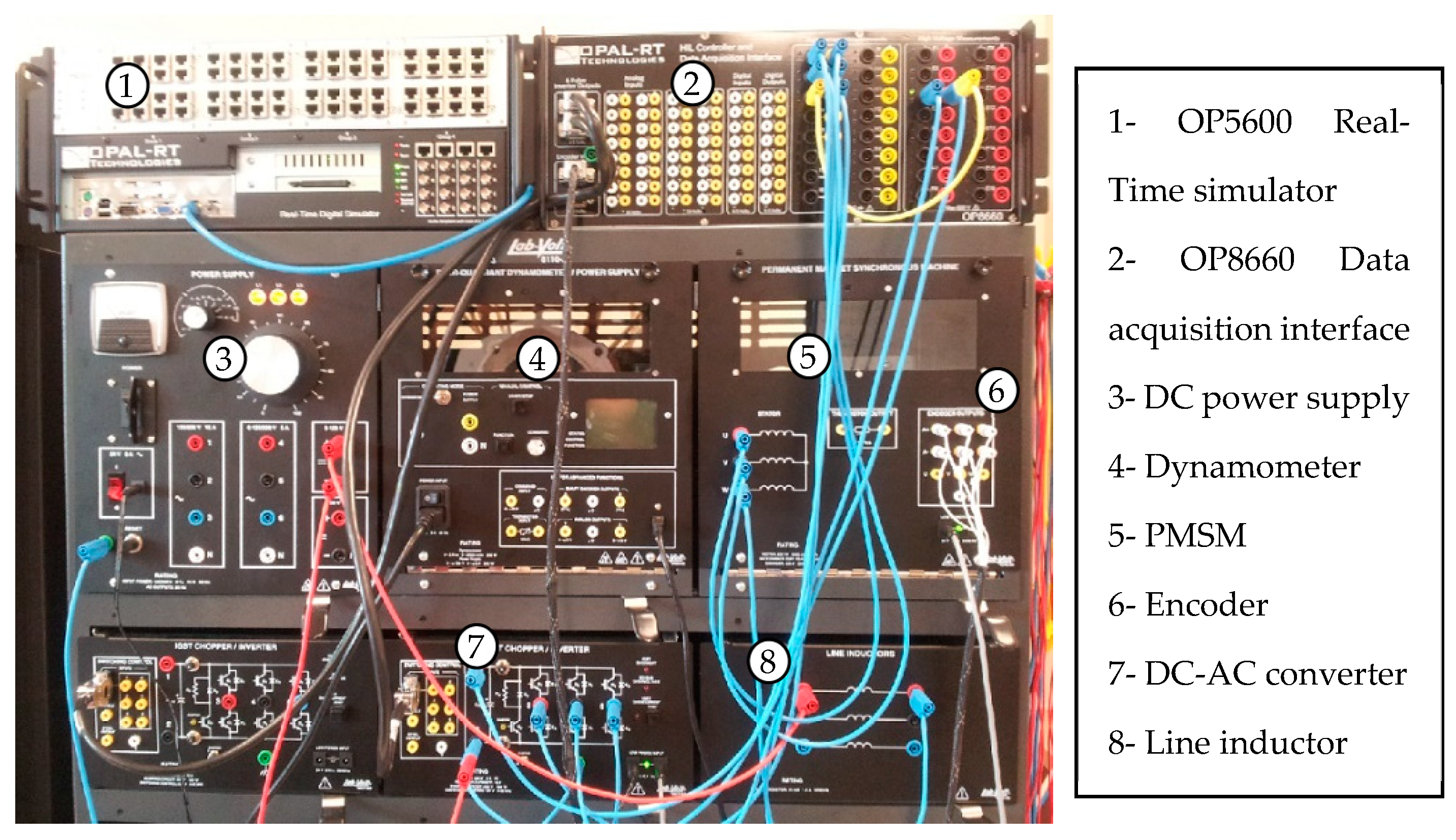
Figure 3.
Schematic of the experimental PMSM drive.
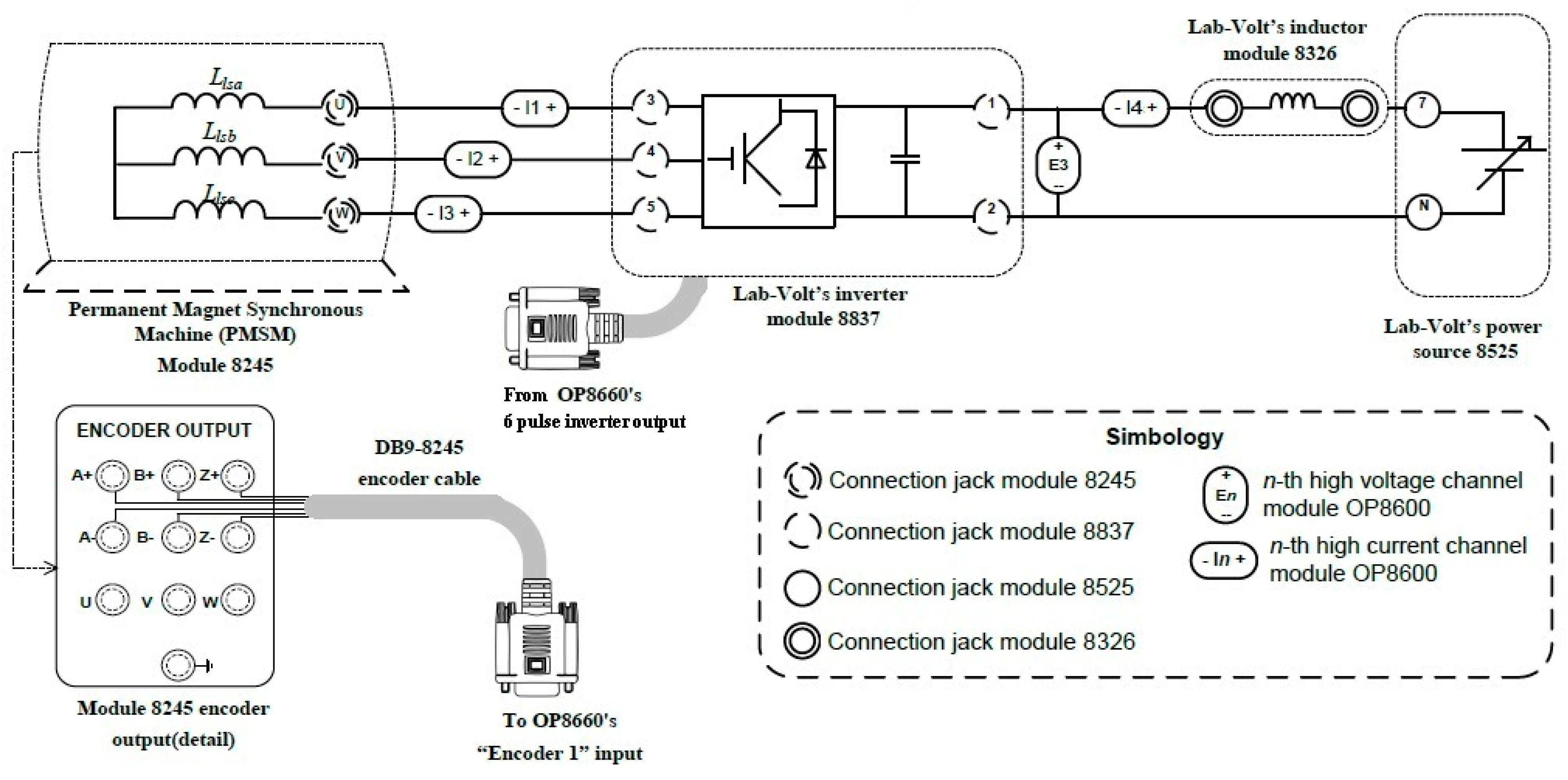
Figure 4.
HIL PMSM drive system.
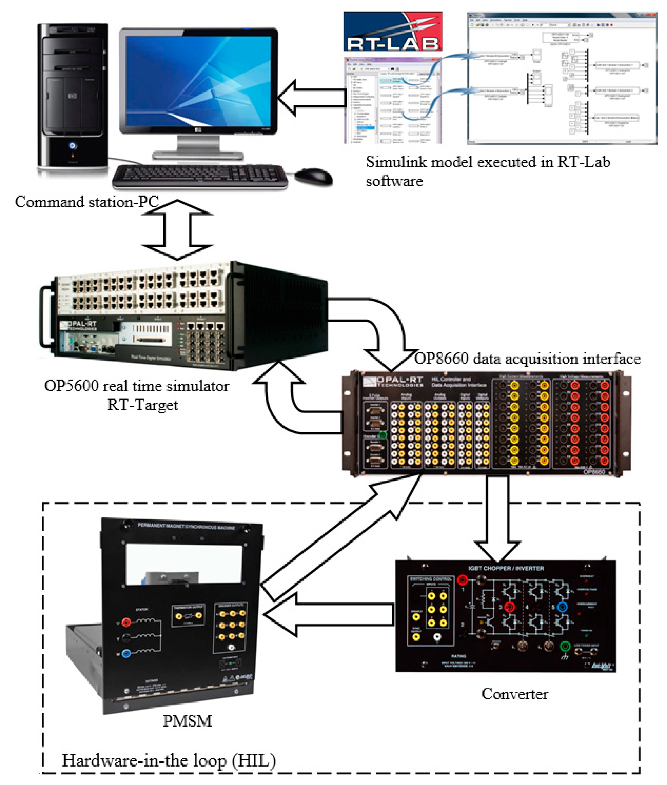
Figure 5.
Tracking response for a variable speed reference (SMC with sgn function). (a) Speed tacking and error; (b) d-q currents tracking and q-command.
Figure 5.
Tracking response for a variable speed reference (SMC with sgn function). (a) Speed tacking and error; (b) d-q currents tracking and q-command.

Figure 6.
Tracking response for a variable speed reference (SMC with modified sgn function). (a) Speed tacking and error; (b) d-q currents tracking and q-command.
Figure 6.
Tracking response for a variable speed reference (SMC with modified sgn function). (a) Speed tacking and error; (b) d-q currents tracking and q-command.

Figure 7.
Speed tracking response under mismatched model. (a) Speed tacking and error; (b) Speed control output (q-command).
Figure 7.
Speed tracking response under mismatched model. (a) Speed tacking and error; (b) Speed control output (q-command).
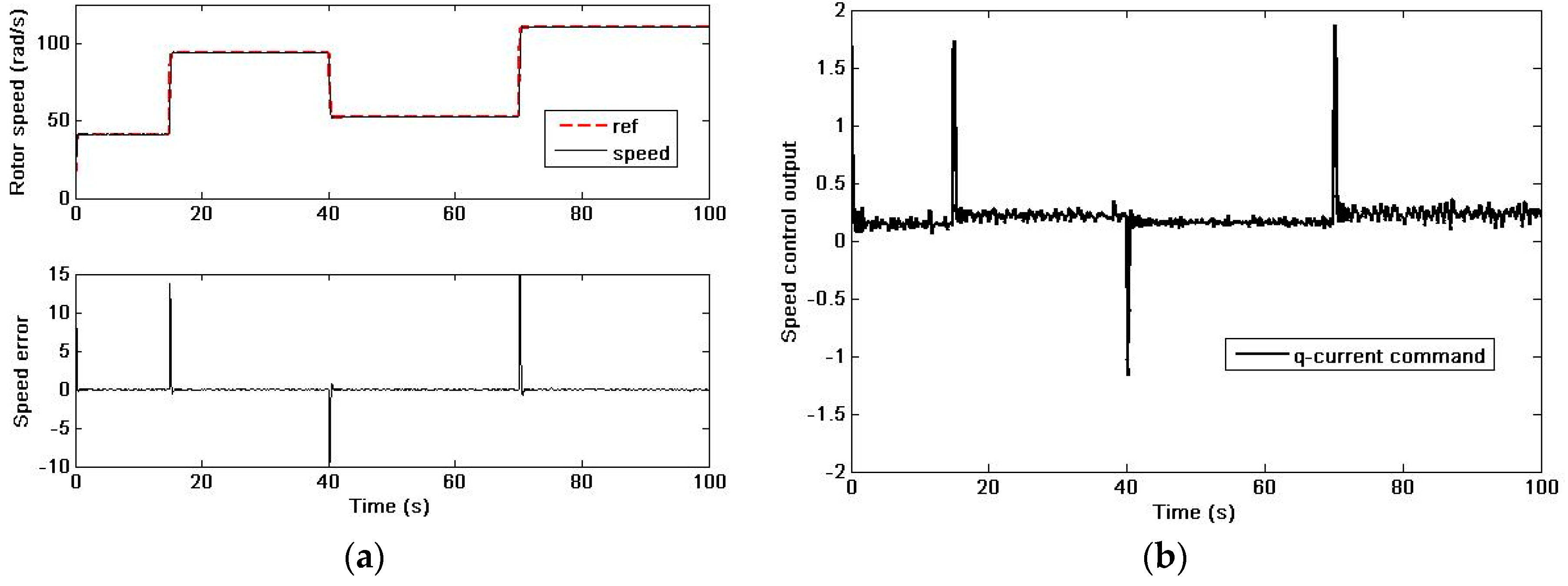
Figure 8.
DC power supply variation (External disturbance).

Figure 9.
Speed tracking response under external disturbance. (a) Speed tacking and error; (b) Speed control output (q-command).
Figure 9.
Speed tracking response under external disturbance. (a) Speed tacking and error; (b) Speed control output (q-command).
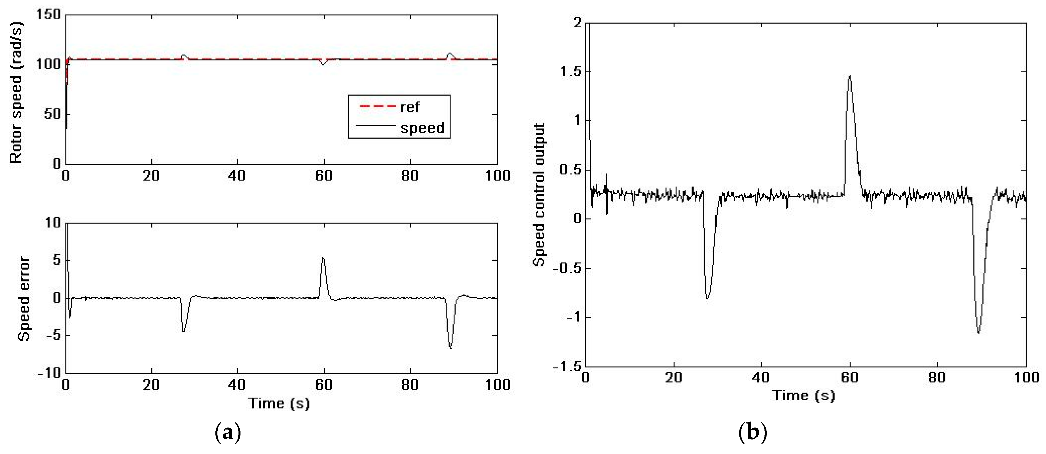
Figure 10.
Speed tracking response under unknown load disturbance. (a) Speed tacking and error; (b) Speed control output (q-command).
Figure 10.
Speed tracking response under unknown load disturbance. (a) Speed tacking and error; (b) Speed control output (q-command).


Table 1.
PMSM parameters.
| Parameter | Unit | Value |
|---|---|---|
| Rated power | W | 260 |
| Rated current | A | 3 |
| Stator resistance | Ω | 1.3 |
| Stator d-axis inductance | mH | 1.5 |
| Stator q-axis inductance | mH | 1.5 |
| Flux linkage | Wb | 0.027 |
| Number of pole pairs | − | 3 |
| Moment of inertia | kg·m2 | 1.7 × 10⁻⁶ |
| Friction coefficient | Nm·s/rad | 0.3141 × 10⁻⁶ |
Table 2.
Control gains.
| Gain | Value |
|---|---|
| Speed control (outer loop) | |
| k1, k2 | 103, 104 |
| δ | 0.2 |
| 0.01 | |
| Current controller (inner loop) | |
| k1, k2 (d-axis) | 102, 103 |
| k1, k2 (q-axis) | 102, 103 |
© 2019 by the author. Licensee MDPI, Basel, Switzerland. This article is an open access article distributed under the terms and conditions of the Creative Commons Attribution (CC BY) license (http://creativecommons.org/licenses/by/4.0/).
Share and Cite
MDPI and ACS Style
Merabet, A. Cascade Second Order Sliding Mode Control for Permanent Magnet Synchronous Motor Drive. Electronics 2019, 8, 1508. https://doi.org/10.3390/electronics8121508
AMA Style
Merabet A. Cascade Second Order Sliding Mode Control for Permanent Magnet Synchronous Motor Drive. Electronics. 2019; 8(12):1508. https://doi.org/10.3390/electronics8121508
Chicago/Turabian StyleMerabet, Adel. 2019. "Cascade Second Order Sliding Mode Control for Permanent Magnet Synchronous Motor Drive" Electronics 8, no. 12: 1508. https://doi.org/10.3390/electronics8121508
Note that from the first issue of 2016, this journal uses article numbers instead of page numbers. See further details here.