Tilted-Beam Switched Array Antenna for UAV Mounted Radar Applications with 360° Coverage


1
School of Electrical and Electronics Engineering, Chung-Ang University, 84 Heukseok-ro, Dongjak-gu, Seoul 06974, Korea
2
School of Electrical Engineering, Korea Advanced Institute of Science and Technology (KAIST), 291 Daehak-ro, Yuseong-gu, Daejeon 34141, Korea
*
Author to whom correspondence should be addressed.
Electronics 2019, 8(11), 1240; https://doi.org/10.3390/electronics8111240
Submission received: 27 September 2019
/
Revised: 24 October 2019
/
Accepted: 27 October 2019
/
Published: 30 October 2019
(This article belongs to the Special Issue Radar Sensor for Motion Sensing and Automobile)
Abstract
:A highly efficient antenna array for unmanned aerial vehicle (UAV) mounted radar applications with a tilted-beam characteristic and a 360° beam coverage is proposed in this paper. The proposed array antenna is configured by four planar super J-pole antennas with 2-dimensional ground reflectors. Each super J-pole antenna element provides a high directivity where the peak gain is tilted about 45° facing toward the ground from the bottom of a UAV body. Thus, the air-to-ground communication difficulty due to the altitude difference between the UAV and ground targets can be effectively solved. Further, the four super J-pole elements with a switched operation can cover the whole 360° areas around the UAV while high antenna gain is maintained. To verify the performance, the proposed structure was implemented at 5.9 GHz with an overall volume of 0.88 × 0.88 × 0.83 λo3. The measured 10-dB impedance bandwidths for all four antenna elements were better than 27.2% and the isolation among the four antenna ports was also always better than 13 dB. The measured peak gain was better than 7.4 dBi and tilted at 45° in the elevation angle. Lastly, the measured half power beam widths in elevation and azimuth planes were more than 60° and 87°, respectively.
1. Introduction
Since the use of unmanned aerial vehicles (UAV) has become an effective technique for various areas, such as aerial security surveillance, public safety, structural health and safety monitoring, automated inventory, and agricultural applications [1,2,3,4,5], UAV-based technologies are being widely studied due to the allowable flexibility and 3-dimensional mobility. Using drones for wireless communication and aerial base stations are other exemplary topics of research [6,7,8,9]. Although there has been a lot of previous research on the integration of wireless sensors, radars, or IoT devices with UAV, including drones, most of the work has focused on the connectivity of UAV using the currently existing antenna structures [10,11]. Since the uniqueness of UAV applications is emphasized by the physical location of communication devices, the conventional antenna structures or previously reported reconfigurable antenna structures [12,13,14,15,16,17,18,19,20,21,22] cannot be effectively used. As described in Figure 1a, the peak antenna line of sight (LoS) should be at a tilted angle from the center of UAV, because the target communication devices or objects are located on the ground, while the UAVs are in the air. This altitude difference makes a planar type antenna like a microstrip patch antenna impractical due to the limited half power beam width (HPBW) that cannot cover the objects distributed widely from the center of UAV. Instead, a simple monopole antenna is typically used, but it suffers from low gain, since high directivity is required for the air-to-ground communication or the ground target detection. Further, dipole antenna might be adopted to increase the directivity, but it still has a limited beam coverage and an insufficient gain.
Thus, a tilted beam with a sufficient gain in the elevation angle of UAV is required for the optimal operation as shown in Figure 1a. Moreover, a wide beam coverage capability in azimuth angles around the center of UAV is required for the optimal UAV antenna. To maximize the mobility of UAV and efficiency of sensor communication or target detection, the antenna beam pattern must cover the whole 360° around the UAV with the sufficient antenna gain. Since a single antenna implementation can rarely satisfy the whole beam coverage with enough antenna gain, multiple antenna integration for beamforming or pattern reconfigurable characteristics is required. Figure 1b shows the example of the 360° beam coverage around the UAV using multiple beam sectors. Every target can be detected by a switchable beam operation if each antenna element has enough HPBW in the azimuth plane. Therefore, in this paper, a new antenna structure having the tilted-beam performance in the elevation angle and the 360° beam coverage in the azimuth angle is proposed for UAV-mounted radar or sensor applications.
2. Analysis of the Proposed Antenna
Figure 2a–d shows the conventional monopole, dipole, J-pole, and super J-pole antennas with corresponding beam patterns, respectively. As previously mentioned, monopole and dipole antennas have limited performances for UAV applications. A planar J-pole, as shown in Figure 2c, has a beam characteristic slightly tilted in the elevation angle. Figure 2d shows a planar super J-pole where one arm is longer than a conventional J-pole, providing slightly higher gain.
Although tilted beam can be made through the conventional J-pole and super J-pole, the antenna gain should be further improved for the better air-to-ground communication of UAV applications. Further, to cover the whole 360° around the UAV with a minimum number of antenna elements, HPBW should be optimized as well. Then, the modified planar super J-pole type antenna structure, as shown in Figure 2e,f, is proposed in this paper for the first time. By adopting a ground reflector as shown in Figure 2e, the angle of tilted beam and gain can be tuned. Further, by integrating one more ground reflector to form a 2-dimensional reflector as shown in Figure 2f, a tilted beam with higher gain can be optimally produced for UAV-mounted sensor applications. Figure 3a shows the complete proposed antenna array configured by the four identical super J-pole antennas with 2-dimensional reflectors. Figure 3b,c shows the top and bottom layer of the single super J-pole antenna element where the top and bottom conducting layers are connected through vias to form an electrically thick conductor.
In order to compare the proposed antenna structure with the conventional J-pole antenna, a simple planar J-pole, a planar J-pole with a 1D reflector, and a planar J-pole with a 2D reflector antennas are designed at 5.9 GHz with a Taconic TLX-9 substrate having a relative permittivity of 2.5 and a thickness of 1.1 mm. Then, the different structures are denoted as type 1, type 2, and type 3, respectively, as shown in Figure 4a–c. Here, type 3 is the proposed single antenna element adopted for the final 1 × 4 array configuration.
Since types 2 and 3 have the ground reflector integrated with the super J-pole antenna element, the capacitive coupling between the reflectors and the radiation elements affects the input impedance, resulting in the impedance variation from the type 1. For example, type 3 has the ground reflectors in both perpendicular and parallel direction. With respect to the antenna elements, the distance between the reflectors and antenna elements must be tuned for an optimal impedance matching. Figure 5a,b shows the changes in return loss characteristic of the type 3, according to the variation in the gap between the reflectors and antenna element. Further, since the arm length of the super J-pole element determines the center frequency, the return loss characteristics with respect to the arm length is also simulated as shown in Figure 5c. Lastly, the simulated return loss characteristics for types 1, 2, and 3 are compared in Figure 5d.
Based on the simulated return characteristics, the parameters for antenna dimension denoted in Figure 3 can be optimized and the values are summarized in Table 1 as shown below.
Once the impedance of the proposed antenna is matched at the desired operation frequency, the radiation pattern should be investigated as well. As mentioned previously, the UAV-mounted antenna array should have tilted-beam characteristics and 360° coverage around the center of UAV. Figure 6 shows the simulated 3D radiation patterns of the 1 x 4 array configured by the proposed super J-pole with a 2D reflector. As shown in Figure 6a, the peak gain is tilted about 45° in the elevation angle. Although antenna 4 is not depicted in Figure 6a due to the limitation of the physically available side-view, the simulated beam patterns for all antennas are almost identical. Further, Figure 6b shows the 3D radiation patterns depending on switched antenna modes in the azimuth angle. If all four antennas are turned on, a donut-shaped monopole-like beam around the center of the proposed array antenna is formed. Further, if two neighboring antennas are turned on simultaneously, a converged beam in between the two antennas is produced. Lastly, if an individual antenna is turned on, corresponding sectors can be covered. It is noted that since each super J-pole element with a 2D reflector has a wide enough beam to cover the whole 360° by individual operations, the simultaneous excitation of multiple antenna elements is not necessary.
The simulated radiation patterns for the individual antennas at the elevation and azimuth angles in polar plots are also shown in Figure 7a,b. The simulated peak gains for antennas 1, 2, 3, and 4 are about 7.6, 7.9, 7.5, and 7.8 dBi, respectively, and the peak gain in the elevation angle is observed at approximately 45° tilted from the center of the proposed array. Further, the minimum HPBWs in the elevation and azimuth planes of the individual antenna elements are about 64° and 108°, respectively.
Since the radiation patterns for different combinations of two-antenna excitation are symmetric, the radiation patterns by antennas 1 and 4 only are simulated, as shown in Figure 7c,d. The peak gain is about 8.6 dBi, and HPBWs in the elevation and azimuth planes are about 65° and 95°, respectively. In addition, Figure 7e,f shows the simulated radiation patterns when all antennas are simultaneously excited, resulting in a monopole-like pattern with a peak gain of 5.9 dBi and HPBW of 43° in the elevation plane. Further, the simulated radiation efficiency and total efficiency, including the mismatch with a feed line, are shown in Figure 8. At the center frequency of 5.9 GHz, both the radiation and total efficiencies show more than 91%. Lastly, to predict the UAV-body effect on the proposed antenna, a simulation has been conducted with an increased ground size of 250 × 250 mm2. Then, the simulated peak gain has been increased to 8.16 dBi since the UAV-body provides more reflection toward the ground level. Although the HPBWs in the elevation and azimuth angles have been slightly decreased to 58° and 87°, respectively, the overall performance has still shown a high gain and wide HPBWs.
3. Measured Results
To verify the proposed structure, the 1 × 4 array antenna having the center frequency of 5.9 GHz was implemented with the same Taconic TLX-9 substrate (relative permittivity of 2.5 and thickness of 1.1 mm) used for simulation. The fabricated antenna has the volume of 45 × 45 × 43 mm3 corresponding to 0.88 × 0.88 × 0.83 λo3 where λo denotes a free space wavelength. The detailed geometric parameters for the proposed antenna can be found in Table 1 and the fabricated antenna is shown in Figure 9.
The return loss and isolation across each antenna element were measured as shown in Figure 10. The center frequency was about 5.9 GHz as expected, and the measured 10-dB impedance bandwidth was better than 27.2%. Further, the measured isolation among each antenna port was always better than 13 dB within the 10-dB impedance bandwidth.
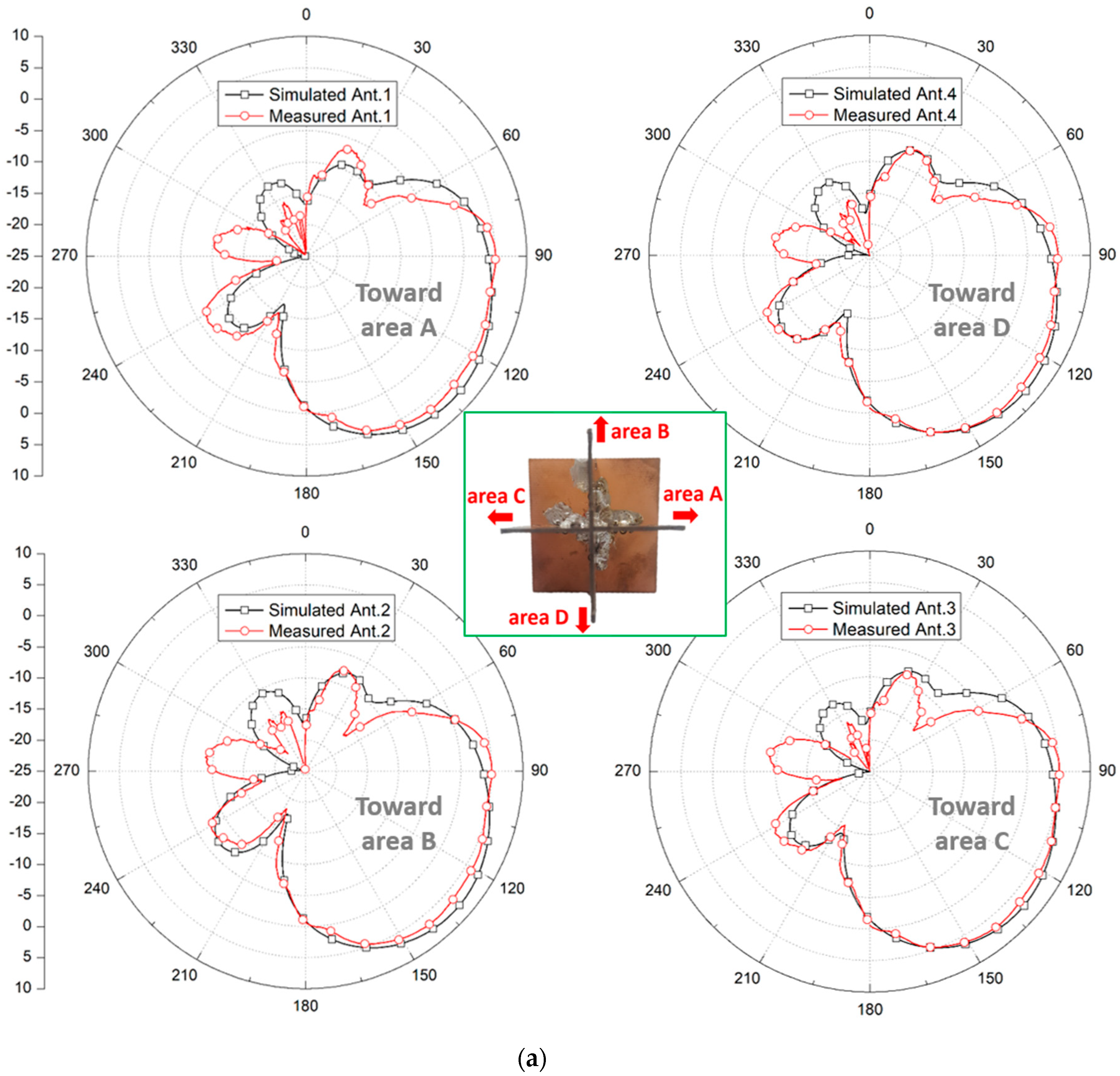
Finally, the radiation patterns in both elevation and azimuth planes were measured at 5.9 GHz, as shown in Figure 11. Compared with the simulated radiation patterns, the measured results show a good agreement in both elevation and azimuth planes. The measured peak gains for antenna elements 1, 2, 3, and 4 were about 7.4, 7.5, 7.8, and 7.6 dBi, respectively. Here, the peak gain in the elevation angle was tilted about 45° from the center of the proposed array antenna. Further, the measured HPBWs of the four antenna elements in the elevation and azimuth planes were better than 60° and 87°, respectively. Although the measured HPBW in the azimuth plane was smaller than the simulated result, the whole 360° coverage could still be satisfied with relatively high gain since the minimum antenna gain of approximately 4 dBi was measured at the overlapped area in between the antenna elements.
4. Conclusions
Due to the unique operation properties of UAV, including drone applications, the radiation peak of the UAV-mounted antenna must be tilted toward the ground from the bottom of UAV. Also, high gain beam pattern covering the whole 360° around UAV must be satisfied. Thus, in this paper, a new antenna array structure optimized for UAV-mounted sensor applications was proposed and verified at 5.9 GHz. The proposed antenna array was configured by four identical super J-pole antennas with 2-dimensional ground reflectors, and the fabricated volume was about 0.88 x 0.88 x 0.83 λo3. Each proposed antenna element showed a tilted beam characteristic in the elevation angle and a wide HPBW around the azimuth angle. The measured 10-dB impedance bandwidth was about 27.2% at the center frequency of 5.9 GHz with the minimum antenna element to element isolation of 13 dB. Further, the measured minimum peak gain and HPBWs in the elevation and azimuth angles were 7.4 dBi, 60° and 87°, respectively.
Author Contributions
Writing—original draft preparation, C.U.L.; investigation and validation, G.N.; formal analysis validation, B.A.; project administration, J.-W.Y.; writing—review and editing, and supervision, H.L.L.
Funding
This research was funded by Institute of Information & communications Technology Planning & Evaluation (IITP) and Chung-Ang University.
Acknowledgments
This work was partly supported by Institute of Information & communications Technology Planning & Evaluation (IITP) grant funded by the Korea government (MSIT) (No. 2017-0-00795, A Study on a small antenna system for vehicle supporting wide elevation angle) and Chung-Ang University Research Scholarship Grants in 2018.
Conflicts of Interest
The authors declare no conflict of interest.
References
- Grimaccia, F.; Bonfante, F.; Battipede, M.; Maggiore, P.; Filippone, E. Risk Analysis of the Future Implementation of a Safety Management System for Multiple RPAS Based on First Demonstration Flights. Electronics 2017, 6, 50. [Google Scholar] [CrossRef]
- Wan, P.; Hao, B.; Li, Z.; Ma, X.; Zhao, Y. Accurate Estimation the Scanning Cycle of the Reconnaissance Radar Based on a Single Unmanned Aerial Vehicle. IEEE Access 2017, 5, 22871–22879. [Google Scholar] [CrossRef]
- Baek, H.; Lim, J. Design of Future UAV-Relay Tactical Data Link for Reliable UAV Control and Situational Awareness. IEEE Commun. Mag. 2018, 56, 144–150. [Google Scholar] [CrossRef]
- Kim, S.J.; Lim, G.J.; Cho, J.; Côté, M.J. Drone-Aided Healthcare Services for Patients with Chronic Diseases in Rural Areas. J. Intell. Robot. Syst. 2017, 88, 163–180. [Google Scholar] [CrossRef]
- Mitcheson, P.D.; Boyle, D.; Kkelis, G.; Yates, D.; Saenz, J.A.; Aldhaher, S.; Yeatman, E. Energy-autonomous sensing systems using drones. In Proceedings of the 2017 IEEE SENSORS, Glasgow, UK, 29 October–1 November 2017. [Google Scholar]
- Ullah, H.; Nair, N.G.; Moore, A.; Nugent, C.; Muschamp, P.; Cuevas, M. 5G Communication: An Overview of Vehicle-to-Everything, Drones, and Healthcare Use-Cases. IEEE Access 2019, 7, 37251–37268. [Google Scholar] [CrossRef]
- Kovalchukov, R.; Moltchanov, D.; Samuylov, A.; Ometov, A.; Andreev, S.; Koucheryavy, Y.; Samouylov, K. Analyzing Effects of Directionality and Random Heights in Drone-Based mmWave Communication. IEEE Trans. Veh. Technol. 2018, 67, 10064–10069. [Google Scholar] [CrossRef]
- Naqvi, S.A.R.; Hassan, S.A.; Pervaiz, H.; Ni, Q. Drone-Aided Communication as a Key Enabler for 5G and Resilient Public Safety Networks. IEEE Commun. Mag. 2018, 56, 36–42. [Google Scholar] [CrossRef]
- Fotouhi, A.; Ding, M.; Hassan, M. Flying Drone Base Stations for Macro Hotspots. IEEE Access 2018, 6, 19530–19539. [Google Scholar] [CrossRef]
- Rahman, M.; Naghshvarianjahromi, M.; Mirjavadi, S.S.; Hamouda, A.M. Bandwidth Enhancement and Frequency Scanning Array Antenna Using Novel UWB Filter Integration Technique for OFDM UWB Radar Applications in Wireless Vital Signs Monitoring. Sensors 2018, 18, 3155. [Google Scholar] [CrossRef]
- Rahman, M.; Naghshvarianjahromi, M.; Mirjavadi, S.S.; Hamouda, A.M. Resonator Based Switching Technique Between Ultra Wide Band (UWB) and Single/Dual Continuously Tunable-Notch Behaviors in UWB Radar for Wireless Vital Signs Monitoring. Sensors 2018, 18, 3330. [Google Scholar] [CrossRef]
- Park, K.; Joung, J.; Lim, S.; Lee, H.L. A Compact Crossed Inverted-V Antenna with a Common Reflector for Polarization Diversity in the IoT. Electronics 2019, 8, 637. [Google Scholar] [CrossRef]
- Row, J.S.; Tsai, C.W. Pattern Reconfigurable Antenna Array with Circular Polarization. IEEE Trans. Antennas Propag. 2016, 64, 1025–1030. [Google Scholar] [CrossRef]
- Zhong, L.; Hong, J.S.; Zhou, H.C. A Novel Pattern-Reconfigurable Cylindrical Dielectric Resonator Antenna with Enhanced Gain. IEEE Trans. Antennas Propag. 2016, 15, 1253–1256. [Google Scholar] [CrossRef]
- Yang, G.; Li, J.; Wei, D.; Zhou, S.G.; Xu, R. Pattern Reconfigurable Microstrip Antenna with Multidirectional Beam for Wireless Communication. IEEE Trans. Antennas Propag. 2019, 67, 1910–1915. [Google Scholar] [CrossRef]
- Tang, M.C.; Duan, Y.; Wu, Z.; Chen, X.; Li, M.; Ziolkowski, R.W. Pattern Reconfigurable, Vertically Polarized, Low-Profile, Compact, Near-Field Resonant Parasitic Antenna. IEEE Trans. Antennas Propag. 2019, 67, 1467–1475. [Google Scholar] [CrossRef]
- Row, J.S.; Huang, Y.J. Reconfigurable Antenna with Switchable Broadside and Conical Beams and Switchable Linear Polarized Patterns. IEEE Trans. Antennas Propag. 2018, 66, 3752–3756. [Google Scholar] [CrossRef]
- Lin, W.; Wong, H.; Ziolkowski, R.W. Wideband Pattern-Reconfigurable Antenna with Switchable broadside and conical beams. IEEE Antennas Wirel. Propag. Lett. 2017, 16, 2638–2641. [Google Scholar] [CrossRef]
- Chen, S.L.; Qin, P.Y.; Lin, W.; Guo, Y.J. Pattern-Reconfigurable Antenna with Five Switchable Beams in Elevation Plane. IEEE Antennas Wirel. Propag. Lett. 2018, 17, 454–457. [Google Scholar] [CrossRef]
- Kittiyanpunya, C.; Krairiksh, M. A Four-Beam Pattern Reconfigurable Yagi-Uda Antenna. IEEE Trans. Antennas Propag. 2013, 61, 6210–6214. [Google Scholar] [CrossRef]
- Juan, Y.; Che, W.; Yang, W.; Chen, Z.N. Compact Pattern-Reconfigurable Monopole Antenna Using Parasitic. IEEE Antennas Wirel. Propag. Lett. 2017, 16, 557–560. [Google Scholar] [CrossRef]
- Li, P.K.; Shao, Z.H.; Wang, Q.; Cheng, Y.J. Frequency—and Pattern—Reconfigurable Antenna for Multi standard Wireless Applications. IEEE Antennas Wirel. Propag. Lett. 2015, 14, 333–336. [Google Scholar] [CrossRef]
Figure 1.
Required optimal antenna performance for unmanned aerial vehicle (UAV)-mounted sensor applications: (a) tilted beam for air-to-ground communication and (b) 360° beam coverage around UAV for target detection.
Figure 1.
Required optimal antenna performance for unmanned aerial vehicle (UAV)-mounted sensor applications: (a) tilted beam for air-to-ground communication and (b) 360° beam coverage around UAV for target detection.

Figure 2.
Different types of potential antennas for UAV-mounted sensor: (a) monopole, (b) dipole, (c) J-pole, (d) super J-pole, (e) super J-pole with a 1D reflector, and (f) super J-pole with a 2D reflector.
Figure 2.
Different types of potential antennas for UAV-mounted sensor: (a) monopole, (b) dipole, (c) J-pole, (d) super J-pole, (e) super J-pole with a 1D reflector, and (f) super J-pole with a 2D reflector.

Figure 3.
Proposed antenna structure showing (a) the complete 1 x 4 array configuration, (b) a top layer, and (c) a bottom layer of the single antenna element.
Figure 3.
Proposed antenna structure showing (a) the complete 1 x 4 array configuration, (b) a top layer, and (c) a bottom layer of the single antenna element.

Figure 4.
Different types of planar super J-pole antennas: (a) conventional, (b) 1D reflector, and (c) 2D reflector configurations.
Figure 4.
Different types of planar super J-pole antennas: (a) conventional, (b) 1D reflector, and (c) 2D reflector configurations.
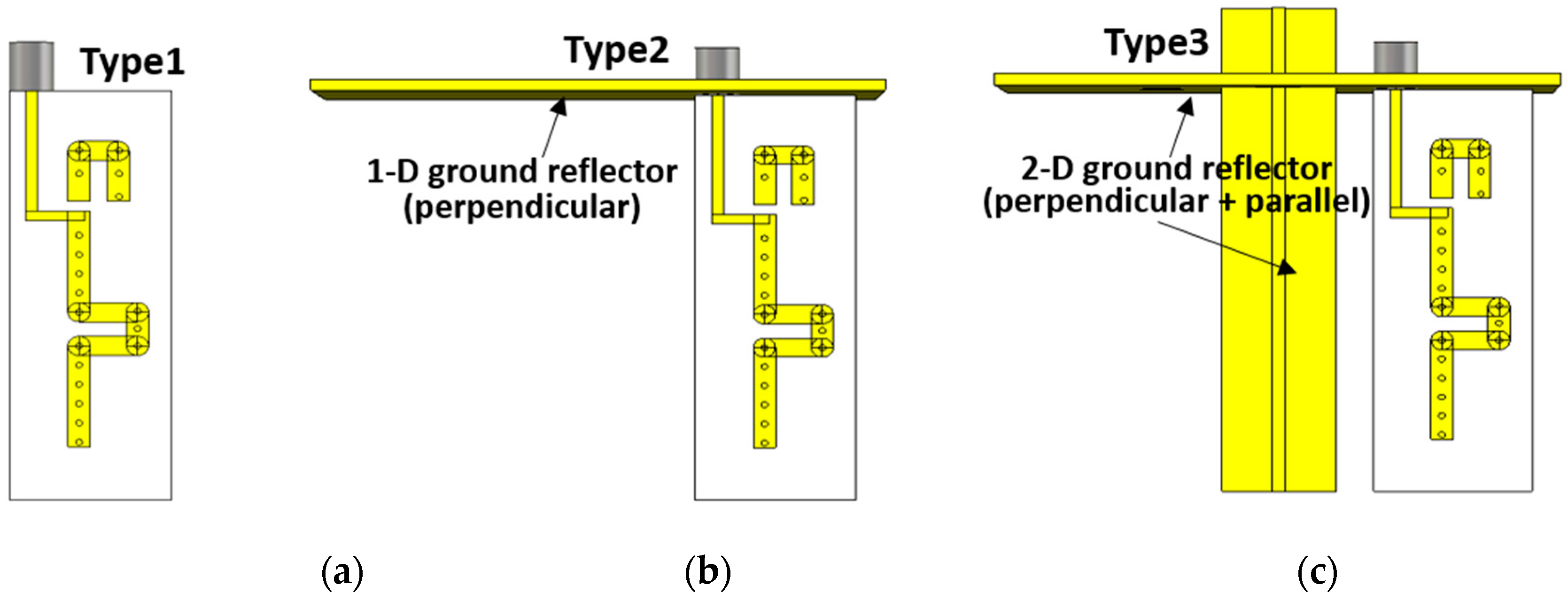
Figure 5.
Simulated return loss characteristics of the proposed antenna, according to the gap between the super J-pole element and (a) parallel reflector, (b) perpendicular reflector, (c) arm length, and (d) comparison of the simulated results for types 1, 2, and 3.
Figure 5.
Simulated return loss characteristics of the proposed antenna, according to the gap between the super J-pole element and (a) parallel reflector, (b) perpendicular reflector, (c) arm length, and (d) comparison of the simulated results for types 1, 2, and 3.
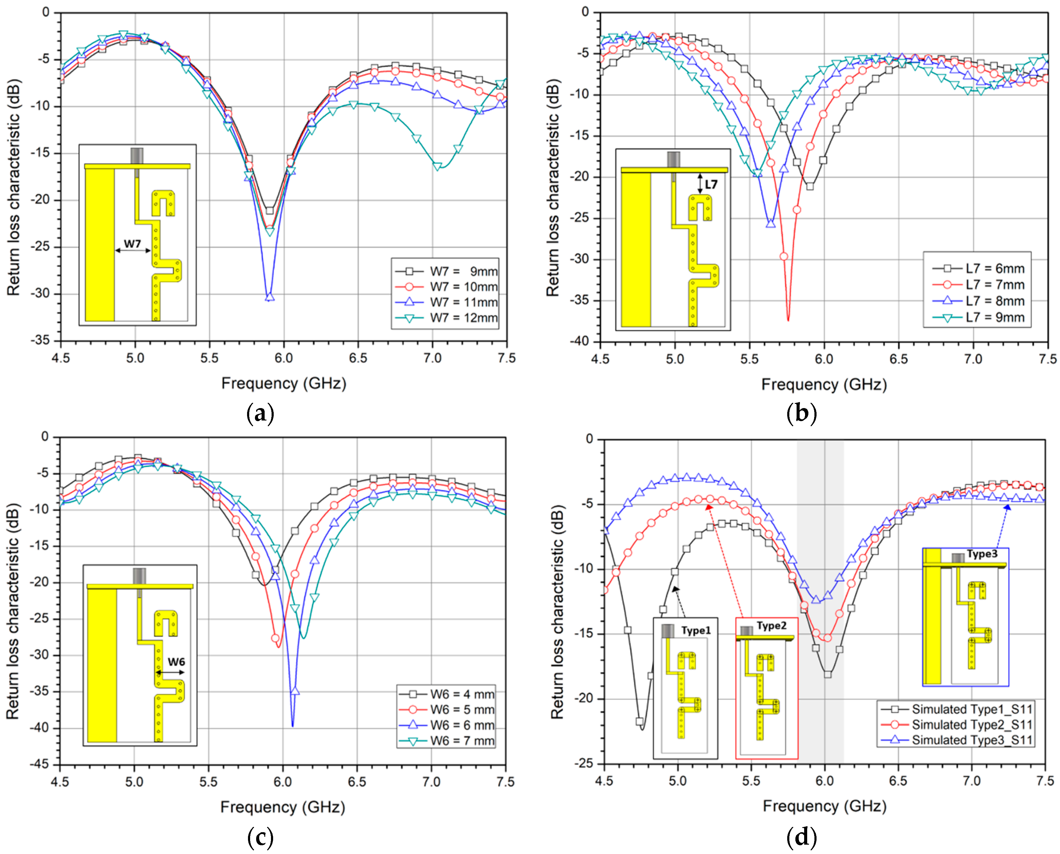
Figure 6.
Simulated 3D radiation patterns of the proposed 1 × 4 array antenna in the (a) elevation angle and (b) azimuth angle.
Figure 6.
Simulated 3D radiation patterns of the proposed 1 × 4 array antenna in the (a) elevation angle and (b) azimuth angle.

Figure 7.
Simulated radiation patterns (a,b): an individual antenna, (c,d): two-antenna, and (e,f): four-antenna excitations in the elevation (left column) and azimuth (right column) planes.
Figure 7.
Simulated radiation patterns (a,b): an individual antenna, (c,d): two-antenna, and (e,f): four-antenna excitations in the elevation (left column) and azimuth (right column) planes.

Figure 8.
Simulated (a) radiation efficiency and (b) total efficiency.
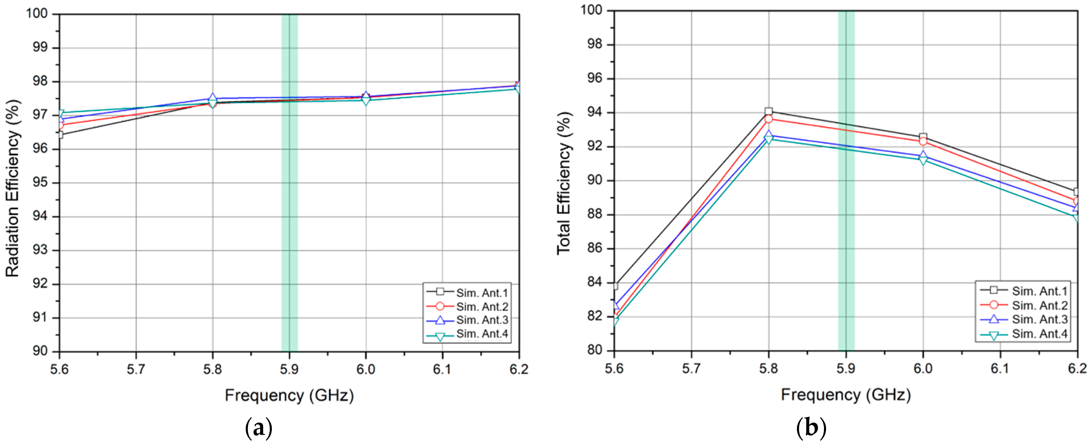
Figure 9.
Fabrication of the proposed array antenna in different views: (a) elevation and azimuth axes, and (b) side-view.
Figure 9.
Fabrication of the proposed array antenna in different views: (a) elevation and azimuth axes, and (b) side-view.
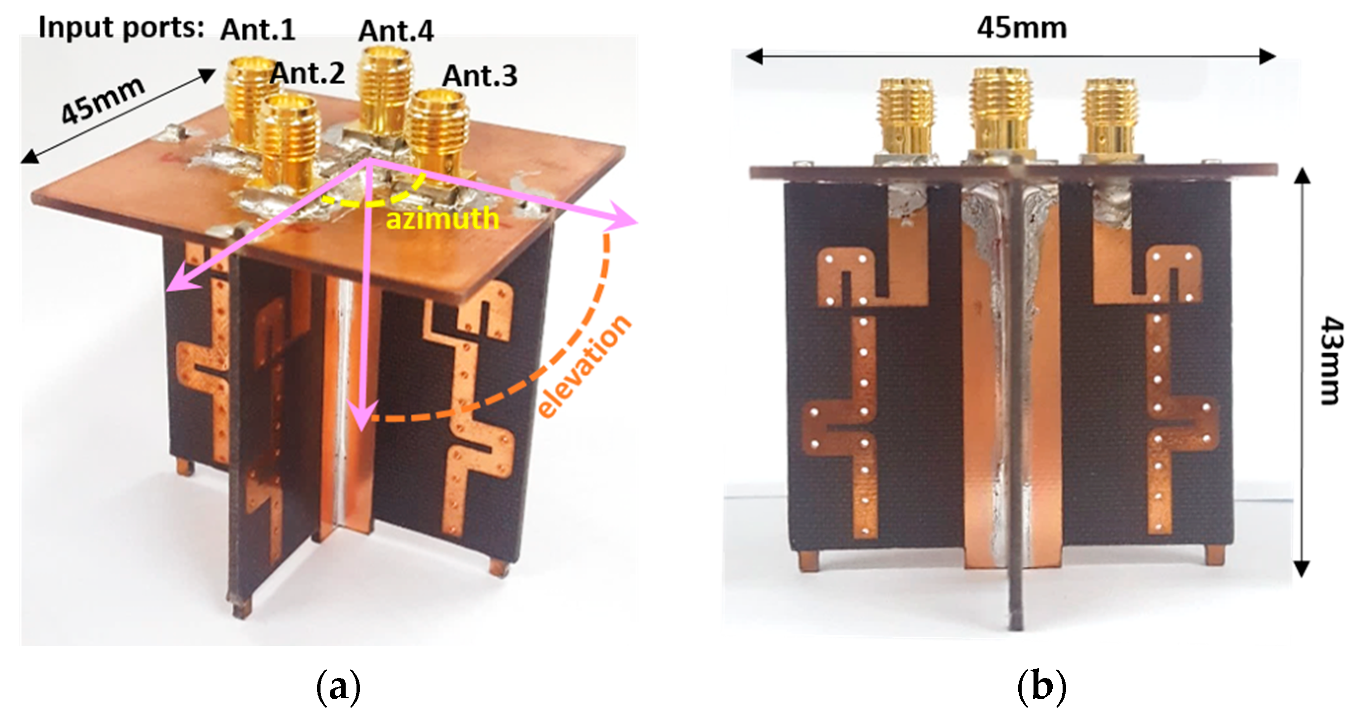
Figure 10.
Measured (a) return loss and (b) isolation characteristics among each antenna port.
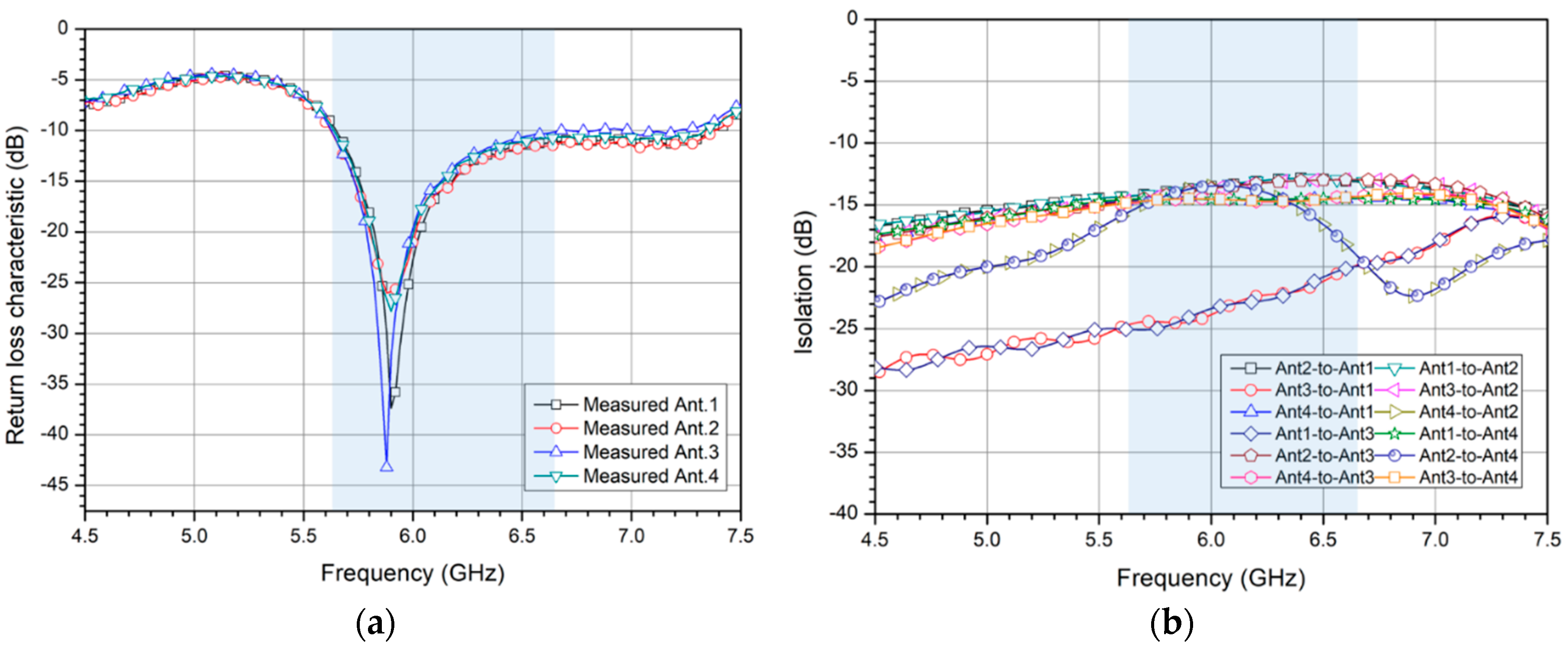
Figure 11.
Simulated and measured radiation patterns of the proposed antenna array in the (a) elevation plane and (b) azimuth plane.
Figure 11.
Simulated and measured radiation patterns of the proposed antenna array in the (a) elevation plane and (b) azimuth plane.


Table 1.
Dimension for the proposed single antenna element referring to the parameters in Figure 3.
Table 1.
Dimension for the proposed single antenna element referring to the parameters in Figure 3.
| Dimension | (mm) | Dimension | (mm) | Dimension | (mm) | Dimension | (mm) |
|---|---|---|---|---|---|---|---|
| L1 | 11.5 | L5 | 13.5 | W1 | 1 | W5 | 5.5 |
| L2 | 5.5 | L6 | 11.5 | W2 | 2 | W6 | 5.3 |
| L3 | 6.3 | L7 | 5.3 | W3 | 7 | W7 | 9.1 |
| L4 | 37 | - | - | W4 | 22.5 | - | - |
© 2019 by the authors. Licensee MDPI, Basel, Switzerland. This article is an open access article distributed under the terms and conditions of the Creative Commons Attribution (CC BY) license (http://creativecommons.org/licenses/by/4.0/).
Share and Cite
MDPI and ACS Style
Lee, C.U.; Noh, G.; Ahn, B.; Yu, J.-W.; Lee, H.L. Tilted-Beam Switched Array Antenna for UAV Mounted Radar Applications with 360° Coverage. Electronics 2019, 8, 1240. https://doi.org/10.3390/electronics8111240
AMA Style
Lee CU, Noh G, Ahn B, Yu J-W, Lee HL. Tilted-Beam Switched Array Antenna for UAV Mounted Radar Applications with 360° Coverage. Electronics. 2019; 8(11):1240. https://doi.org/10.3390/electronics8111240
Chicago/Turabian StyleLee, Cheol Ung, Gunhark Noh, ByungKuon Ahn, Jong-Won Yu, and Han Lim Lee. 2019. "Tilted-Beam Switched Array Antenna for UAV Mounted Radar Applications with 360° Coverage" Electronics 8, no. 11: 1240. https://doi.org/10.3390/electronics8111240
Note that from the first issue of 2016, this journal uses article numbers instead of page numbers. See further details here.